

Page 1
Part# DFCM-1 1
Dynatek • 164 S. Valencia St. Glendora CA 91741
www.dynaonline.com 800.928.3962
User Manual
Parts List
FI Controller
Installation Guide
Wire tap
Wire ties
Velcro
®
Strip
Alcohol Swab
2002-2005 Honda VTX1800
Part Number DFCM-1
2801191 Rev 06-28-05
Congratulations on your purchase of this Dynatek product.
Please take a moment to read these instructions completely before
installing the FI controller. The installation will only take a few minutes,
but proper setup for your specific bike will take longer
Page 2
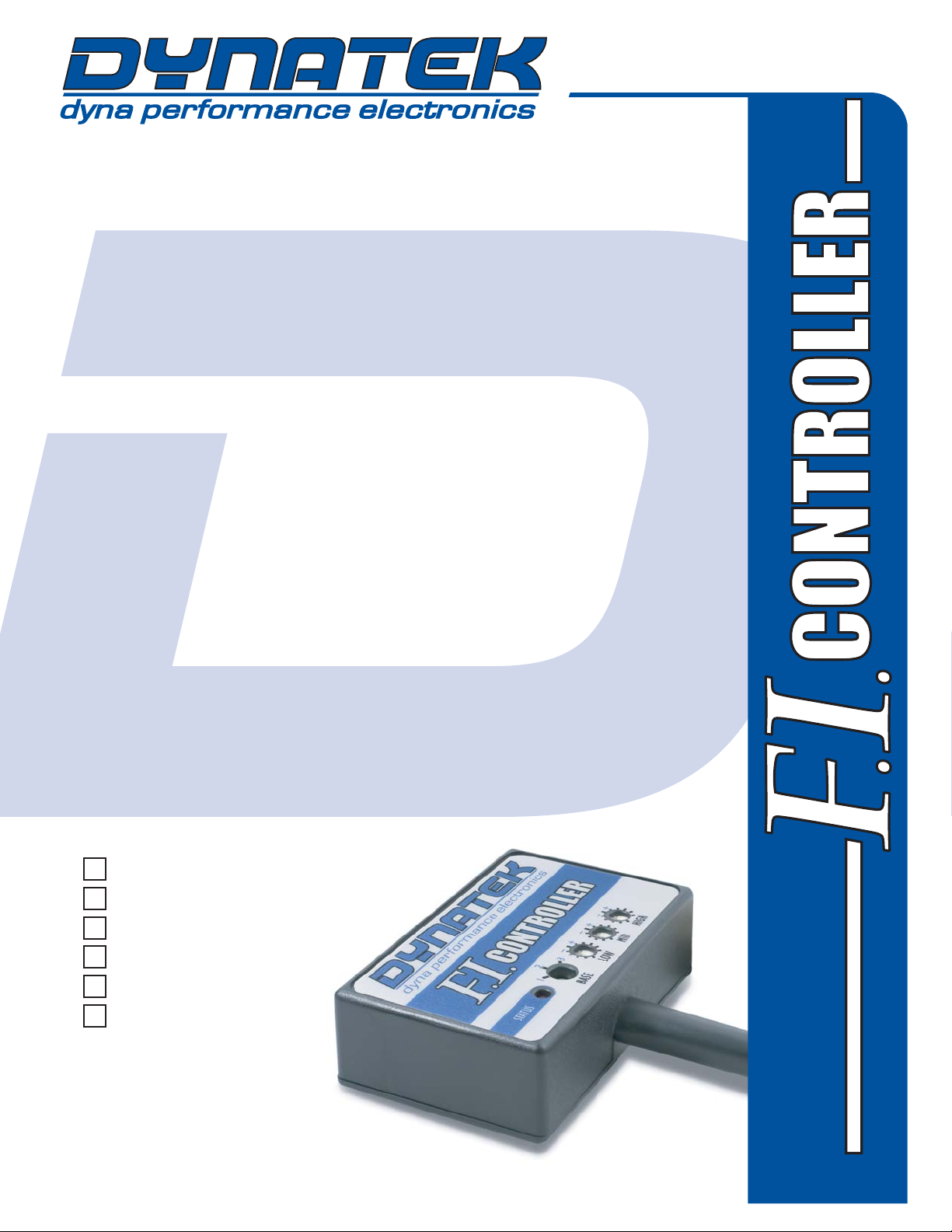
Remove the seat and airbox assembly. Move
the ECU out of the way. Remove the battery
cover.
Connect the FIC ground to the battery
ground.
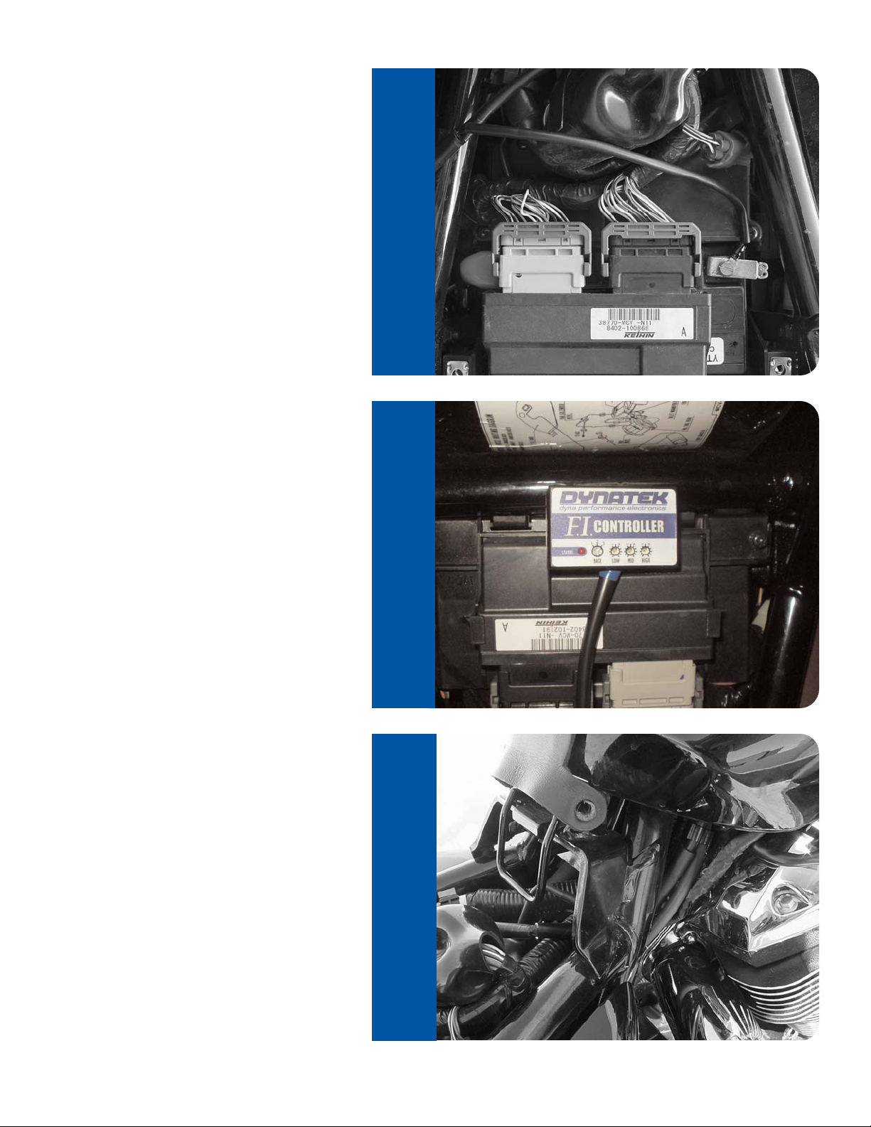
Reinstall the battery cover, and reinstall the
ECU. Using the supplied velcro, mount the
FIC.
Route the wiring harness from the FIC under
the tank and through the frame.
STEP 1
STEP 3
STEP 2
Installation
Part# DFCM-1 2
STEP 3
STEP 2
STEP 1
Page 3

Unplug the harness from the stock injectors.
Make sure to keep track of which connector
is for the front injector.
On the FIC harness, find the connector pair
that has the orange wires. Plug one side of it
into the stock harness for the front injector.
Plug the other side of this harness into the
stock injector. Repeat this step for the rear
cylinder and the other FIC injector harness.
The Throttle Position Sensor(TPS) is located
on the front side of the throttle bodies, behind
the airbox. Unplug this connector.
STEP 4STEP 6 STEP 5
STEP 4
STEP 6
STEP 5
Installation
Part# DFCM-1 3
Page 4

On the TPS harness, locate the red wire that
has a yellow stripe. Using the supplied wire
tap, tap into that wire. Make sure that the tap
is on the wire securely. Connect the grey wire
from the FIC harness to this connector.
Reinstall the seat and airbox assembly.
STEP 7
STEP 7
Installation
Part# DFCM-1 4
Page 5

Controls
The FI Controller is preprogrammed with 4 base fuel
curves. The curves are selected using the switch
labeled BASE. These curves adjust fuel delivery
based on throttle position and RPM, providing the
right amount of fuel under all conditions. The 4 fuel
curves correspond to varying levels of performance
modifications. The levels of modification are broken
down into the following groups.
Base Curve 1 - Stock exhaust and stock or aftermarket air filter.
Base Curve 2 - Slipon exhaust and aftermarket air filters.
Base Curve 3 - Full exhaust systems and aftermarket
air filters.
The fourth curve has all of the fuel adjustment values
zeroed out. This curve is selected by moving the
rotary switch to any position other than Base 1, Base
2 or Base 3. This curve is useful for those wanting to
just modify the fuel delivery with the potentiometer
adjustment, without having any other adjustments.
In addition to the 4 curves, there are 3 potentiometers
that allow you to fine tune the curve you select. These
potentiometers allow you to adjust the fuel curve from
+20% to -20% in 3 different RPM ranges. The RPM
ranges are:
LOW Idle - 2000 RPM
MID 2000 - 4000 RPM
HIGH 4000 - 6000 RPM
To add fuel, turn the potentiometer clockwise. To
subtract fuel, turn the potentiometer counterclockwise.
With the potentiometer pointed straight up at the thick
tick mark (towards the Dynatek logo), that is 0%
adjustment. Fully counterclockwise is -20%, and fully
clockwise is +20%. Adjusting the potentiometer
between these points will result in adding or subtracting
an amount of fuel proportional to how far the knob
was moved from zero.
Calibration
To select the right curve, start by making sure that all
3 of the RPM pots are set to zero adjustment. Then
select the base curve which corresponds to the bikes
level of modification. This should make the bike run
better at all RPMs. The AF ratio if measured on a
dyno should be much smoother throughout the RPM
range than without the FI Controller. If it feels worse
or the AF ratio gets too lean at any RPM compared to
stock, try a different curve.
Once you have selected the correct curve, then you
can fine tune any problems with the map by using the
potentiometers. With the arrows on the pot straight up
and down, the pots are at 0% adjustment. To add
more fuel, turn the pots clockwise. To subtract fuel,
turn the pots counterclockwise. Do not attempt to
adjust while riding!
For models equipped with an oxygen sensor, you will
need to purchase an O2 sensor bypass (Dyna part #
1109011). California "C" models will require one O2
sensor bypass, and California "Retro" models will
require two O2 sensor bypass kits.
Troubleshooting
If the STATUS LED does not come on when the
ignition is switched on, there is no power to the FI
Controller. Make sure that you have the ground
hooked up properly either directly to the battery
ground, or to a lug on the frame that is grounded.
If the LED comes on, but does not run on one or both
cylinders, double check all connections at the injector,
making sure the connectors are seated properly.
For Tech Support: 800.928.3962
 Loading...