

Page 1

LIMITADOR DE VELOCIDAD/
OVERSPEED GOVERNOR/
LIMITEUR DE VITESSE/
GESCHWINDIGKEITSBEGRENZER/
QUASAR
INSTRUCCIONES DE USO Y MANUTENCIÓN/
INSTRUCTIONS FOR USE AND MAINTENANCE/
INSTRUCTIONS D’USAGE ET ENTRETIEN/
GEBRAUCHS- UND WARTUNGSANLEITUNG/
Page 2
Page 3
INSTRUCTIONS: QUASAR Cod: DYN 48.1.07
Fecha: 04/12/2017 Revisión: 07
0
INSTRUCTIONS FOR USE AND MAINTENANCE
_________________________________________________________
1
GENERAL INSTRUCTIONS ................................................................................................................................. 1
2OVERSPEED GOVERNOR IDENTIFICATION .................................................................................................... 1
3MAIN COMPONENTS ........................................................................................................................................... 1
4WORKING PRINCIPLES. ..................................................................................................................................... 2
5FIXING TO THE SLAB .......................................................................................................................................... 6
6UCM UNCONTROLLED MOVEMENT DEVICE ................................................................................................... 6
7TECHNICAL FEATURES ..................................................................................................................................... 8
8INSTRUCTIONS FOR USE AND MAINTENANCE. ............................................................................................. 8
9QUASAR GOVERNOR’S GENERAL DIMENSIONS ........................................................................................... 9
_________________________________________________________
Note: This manual displays partial information on the instructions for use and maintenance of this product. Please refer to the customer
area in Dynatech’s website in order to consult the full manual; http://customers.dynatech-elevation.com/
Page 4
INSTRUCTIONS: QUASAR Cod: DYN 48.1.07
Fecha: 04/12/2017 Revisión: 07
1
1 GENERAL INSTRUCTIONS
Quasar overspeed governor is a compact governor with a 120-mm pulley.
This governor is of a standard type, that is to say, it may be installed both in the machine room and within the shaft.
Its reduced size makes its installation easier in those locations where saving space is a key factor
This governor is designed to be installed on homelifts and lifts with little or reduced traffic.
In case of overspeed, the governor trips the safety gear to stop the car.
It is strictly forbidden:
a) To modify or replace the overspeed governor adjustment spring.
b) Use an overspeed governor in a lift for which it is not intended, or whose features do not correspond to those
marked on the lift (e.g. nominal speed or rope type).
c) To adjust any component of the overspeed governor, except for those parts specified in the manual.
DYNATECH DYNAMICS & TECHNOLOGY, SL will not be liable for any damage caused by failure to observe any
of these general conditions.
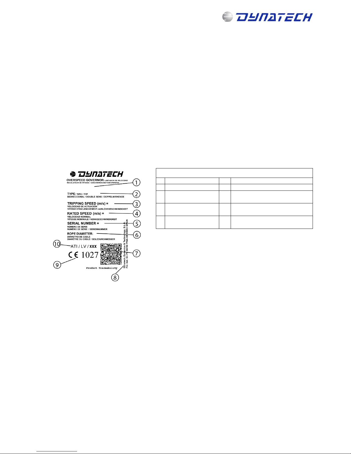
2 OVERSPEED GOVERNOR IDENTIFICATION
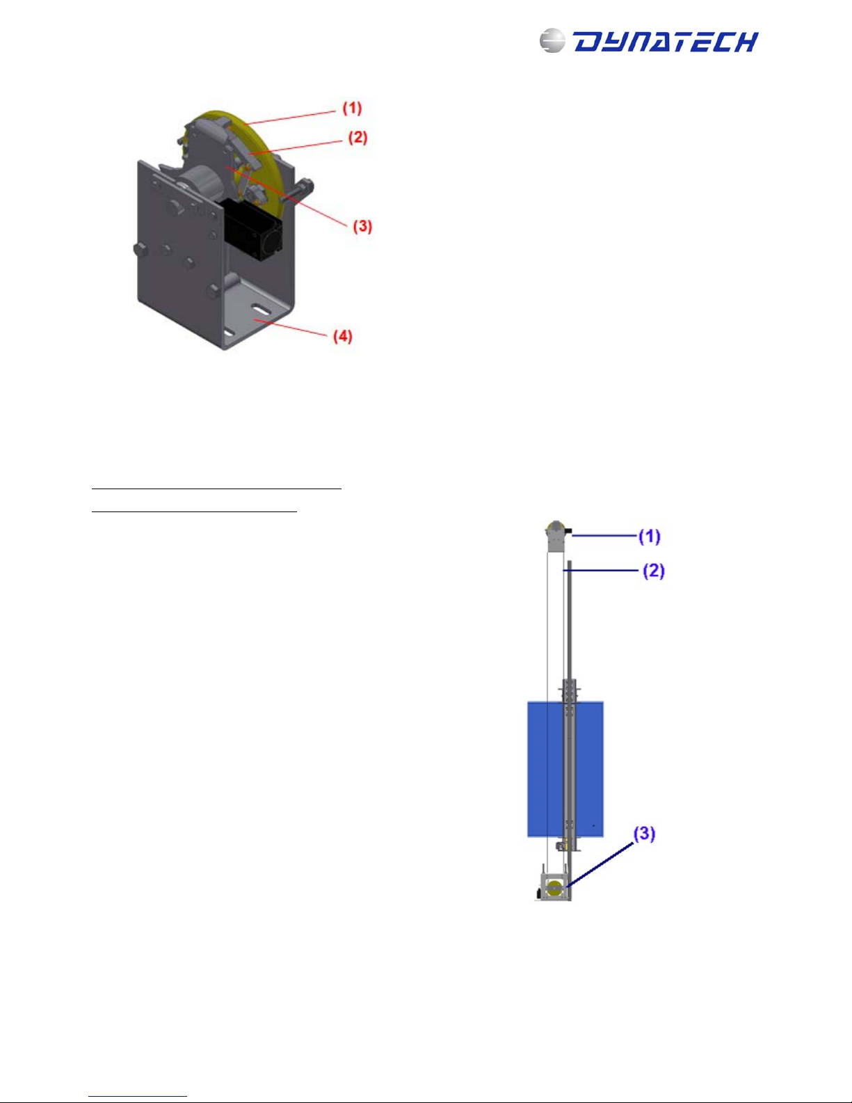
3 MAIN COMPONENTS
Please find below a figure of the Quasar governor displaying its main components.
OVERSPEED GOVERNOR IDENTIFICATION LABEL
1 Governor model 6 Rope diameter (mm
)
2 Governor type 7 QR product traceability code
3
Performance speed
(
m/s
)
8 Dynatech address
4 Rated speed (m/s) 9
Quality assurance CE marking
and notified bod
y
number
5 Serial number 10
EU type examination certificate
number
Note: This manual displays partial information on the instructions for use and maintenance of this product. Please refer to the customer
area in Dynatech’s website in order to consult the full manual; http://customers.dynatech-elevation.com/
Page 5
INSTRUCTIONS: QUASAR Cod: DYN 48.1.07
Fecha: 04/12/2017 Revisión: 07
2
Where:
(1) - Main pulley
(2) - Centrifugal system
(3) - Locking system
(4) – Governor’s fixing
4 WORKING PRINCIPLES.
The governor is of the centrifugal type, and can be unidirectional or bidirectional.
The ropes which can be used for this governor are:
Rope of 6.5 mm Gustav Wolf PAWO 819W
Rope of 6 and 6,5 mm Drako 250 T
The governor is directly anchored to the slab in the
machine room or to the upper part of the lift shaft, linked
to its tensioning pulley in the pit via the rope.
The rope runs along the governor and the tensioning
pulley’s groove.
The ends of the rope are fixed to the driving bar’s cable
ties. This way, when the car reaches the tripping speed,
the movement concerning the governor rope will cause
it to lock.
The working diagram is as follows:
(1) QUASAR governor
(2) Governor’s rope
(3) Tensioning Pulley
As previously mentioned, the governor is anchored to the slab, either in the machine room or at the upper part of the
lift’s shaft.
The ends of the rope (2) are fastened to the governor’s attachment (1) of the driving bar by using thimbles and cable
clips.
Note: This manual displays partial information on the instructions for use and maintenance of this product. Please refer to the customer
area in Dynatech’s website in order to consult the full manual; http://customers.dynatech-elevation.com/
Page 6
INSTRUCTIONS: QUASAR Cod: DYN 48.1.07
Fecha: 04/12/2017 Revisión: 07
3
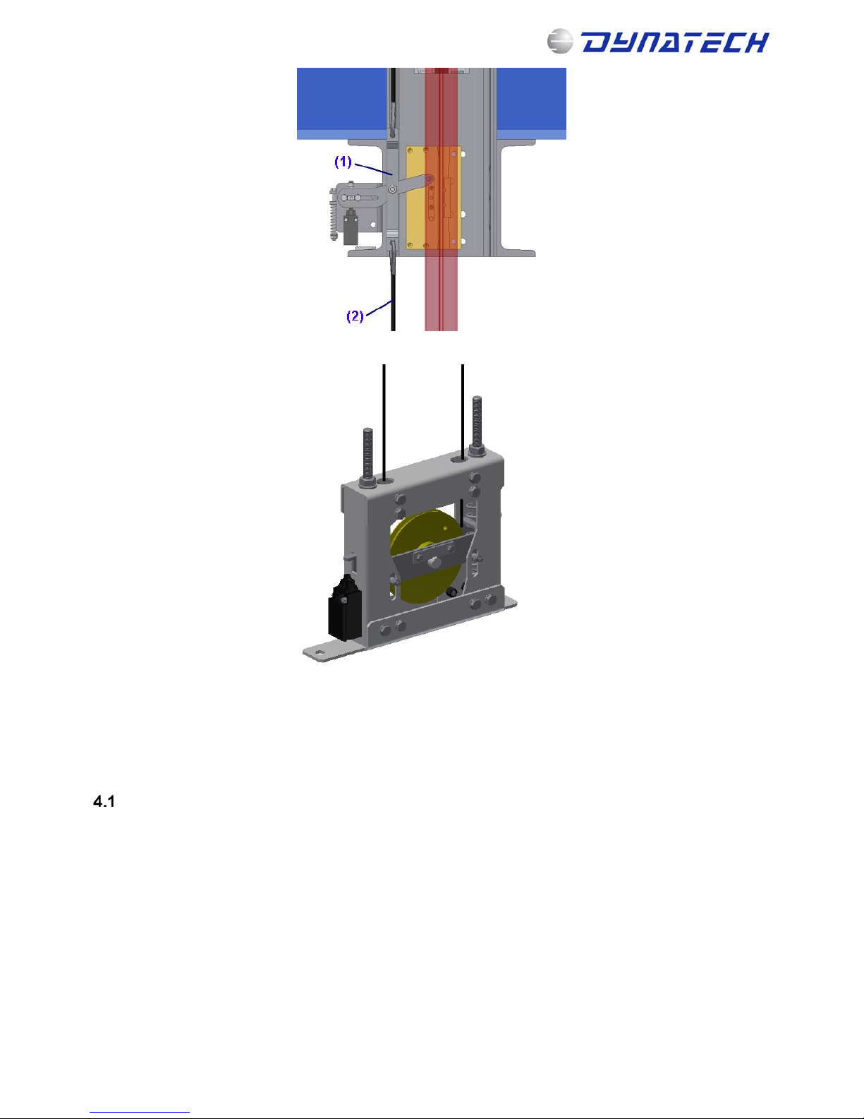
The tensioning pulley is located in the hoistway pit.
The rope is to be tightened enough for the governor to be able to transmit the force required to trip the safety gear.
Should the rope become untightened or break, there is a de-tensioning contact that would interrupt the safety line in
any of the cases.
NB. The Quasar governor uses special ropes. Carefully read the Compact tensioning pulley 126 manuals for their
proper installation.
OVERSPEED CONTACT
The governor incorporates an overspeed contact (1) as displayed in the image on the right.
In this governor, electrical tripping occurs just before the governor interlocks. Thanks to a return mechanism in the
interlocking system, the electrical contact does not require to be manually reset. The contact is automatically reset.
This means that, once the governor and safety gear have been tripped, just unjam the safety gear and the governor
will return to its standby position.
Note: This manual displays partial information on the instructions for use and maintenance of this product. Please refer to the customer
area in Dynatech’s website in order to consult the full manual; http://customers.dynatech-elevation.com/
Page 7
INSTRUCTIONS: QUASAR Cod: DYN 48.1.07
Fecha: 04/12/2017 Revisión: 07
4
REMOTE OPERATION
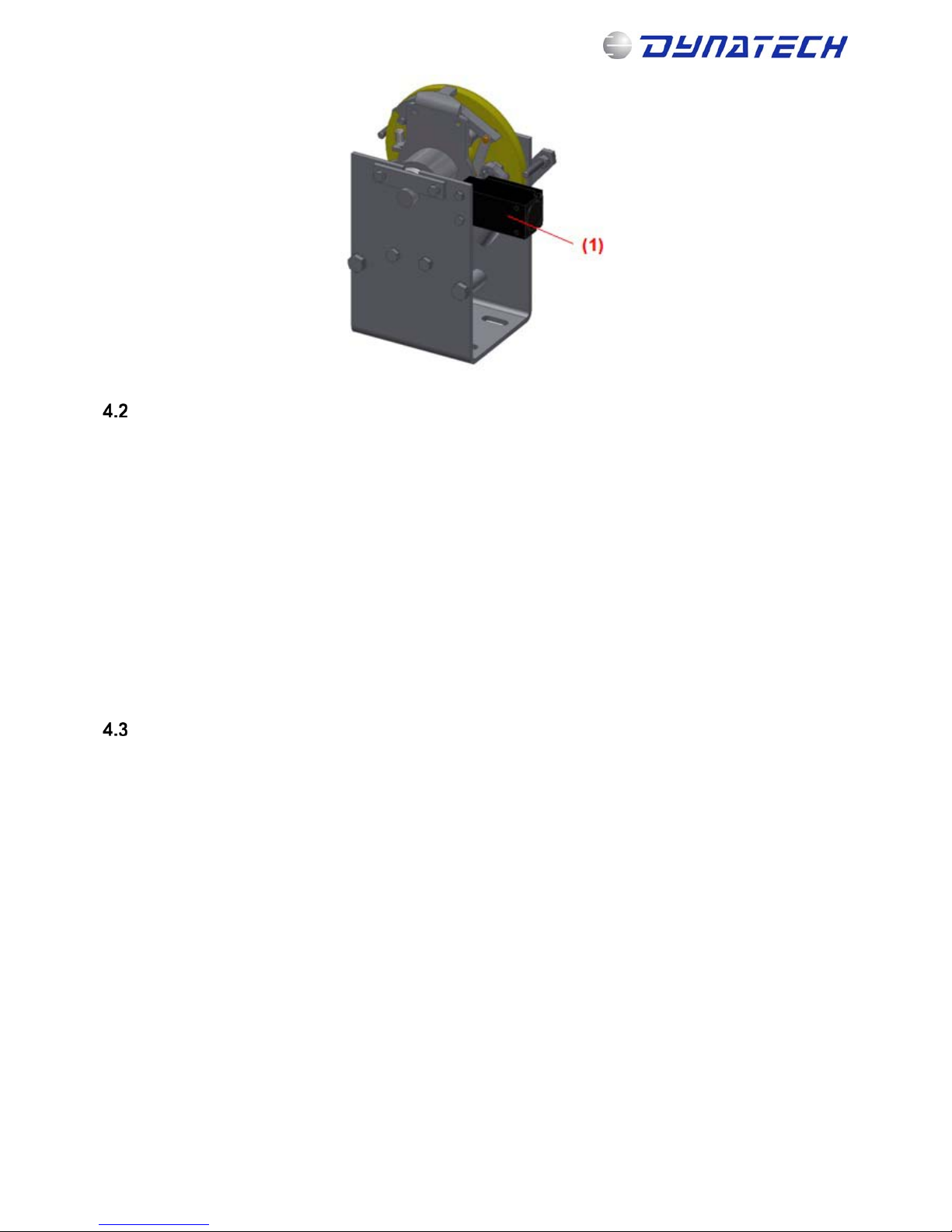
The governor incorporates a remote jamming system to check for the correct interlocking of the governor and the
subsequent jamming of the safety gear.
It is basically made up of a remote electromagnetic interlocking system that may be operated from the machine room.
There are three versions available for the installer to choose at his/her convenience.
24 V DC (Direct current) powered coil. A 1.2 A current must be guaranteed.
48 V DC (Direct current) powered coil. A 0.5 A current must be guaranteed.
190 V DC (Direct current) powered coil. A 0.16 A current must be guaranteed.
Note: In any case, only a few seconds are required to interlock the governor. After operation, the power feeding the
coil is to be cut so as not to excessively overheat it. That is the reason why it is recommended to operate the system
via a pushbutton.
The figure displays both the device and its location within the unit (1)
TEST PULLEY
As an option, the Quasar governor may be supplied with a test pulley. The figure on the right displays its location at
the rear of the main pulley.
To test jamming, move the rope in the main pulley to the test pulley; this way, the governor will interlock at the rated
speed of the lift, thus jamming the safety gears.
Note: This manual displays partial information on the instructions for use and maintenance of this product. Please refer to the customer
area in Dynatech’s website in order to consult the full manual; http://customers.dynatech-elevation.com/
Page 8
INSTRUCTIONS: QUASAR Cod: DYN 48.1.07
Fecha: 04/12/2017 Revisión: 07
5
QUASAR GOVERNOR’S COVER
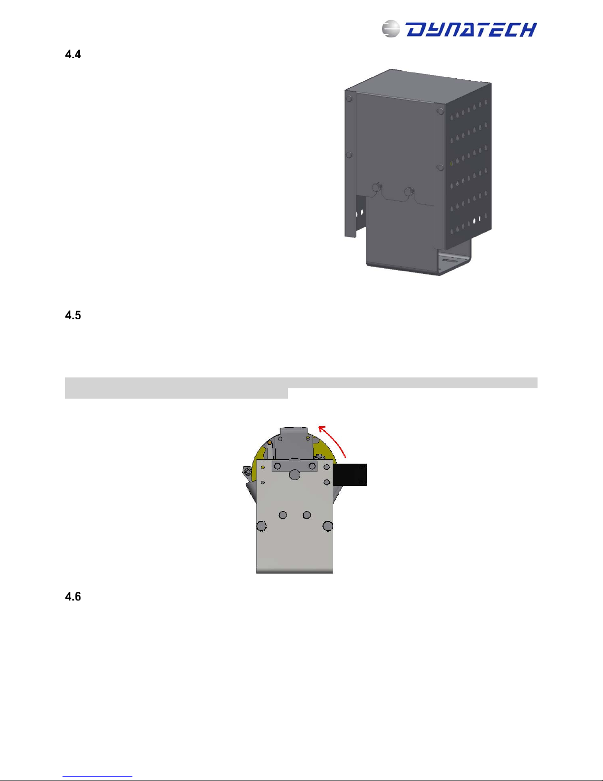
As an option, a cover may be installed for the governor
in order to avoid bumps, entanglement or other damage
caused by the rotation of the governor’s mobile parts.
This is a cover reaching the main part of the governor.
It is easy to assemble
QUASAR LS
There is a low speed QUASAR governor called QUASAR LS.
The minimum performance speed is 0.30 m/s
This governor is DOWNWARDS ACTING ONLY and the performance speed range is: 0.30 – 0.70 m/s
Important Note: Customers asking for a QUASAR LS, may know that it´s unidirectional. In order to know the right
way, it must pay attention to the arrow in the governor.
ONE-WAY QUASAR OVERSPEED GOVERNOR
The QUASAR overspeed governor may be sent for any speed as a one-way overspeed governor.
Attention must be paid to the direction of rotation of the overspeed governor when it is one-way.
Note: This manual displays partial information on the instructions for use and maintenance of this product. Please refer to the customer
area in Dynatech’s website in order to consult the full manual; http://customers.dynatech-elevation.com/
Page 9
INSTRUCTIONS: QUASAR Cod: DYN 48.1.07
Fecha: 04/12/2017 Revisión: 07
6
5 FIXING TO THE SLAB
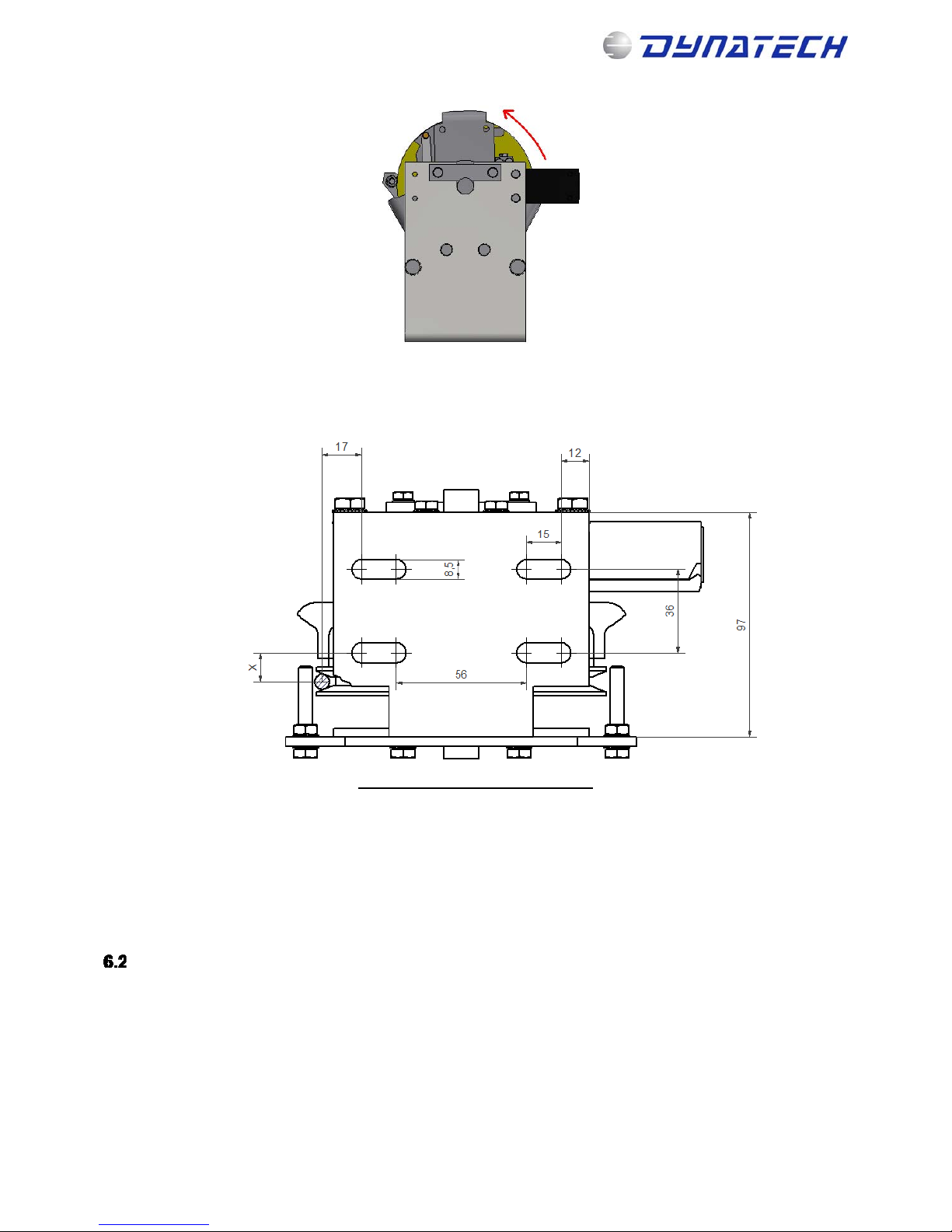
The figure displays the governor’s anchoring points to the slab: Measurements are given in millimetres.
X=12.5 mm Quasar (6/6,5 mm rope)
The figure above displays the floor plan view of the governor’s motherboard.
The governor is anchored to the slab via the slotted holes on the board.
It also displays the rope and its location with reference to the motherboard.
6 UCM UNCONTROLLED MOVEMENT DEVICE
UCM WARNINGS
The anti-creep system requires the lift controller to be able to manage the functions that the anti-creep system uses,
such as the coil power, control sensor monitoring and manual rescue. If the controller is unable to manage these
functions, Dynatech offers the possibility of installing an electronic module, D-Box. For more information, see the
website.
If the D-Box is not used, please observe the following warnings and follow the recommendations below for proper
controller design.
Note. It is highly recommended that the controller designer contacts Dynatech before designing the circuit to
manage the anti-creep system, to clarify any doubts regarding connections and to be recommended a specific
solution for their installation
Note: This manual displays partial information on the instructions for use and maintenance of this product. Please refer to the customer
area in Dynatech’s website in order to consult the full manual; http://customers.dynatech-elevation.com/
Page 10
INSTRUCTIONS: QUASAR Cod: DYN 48.1.07
Fecha: 04/12/2017 Revisión: 07
7
- Locking the overspeed governor after UCM can be done by either of the following 2 methods: 1)
Detecting the UCM or 2) Letting the anti-creep system act.
1) To detect the UCM, either a sensor needs to be placed on each floor or, as is the case with the D-Box, a
levelling signal needs to be used. Therefore, if the car creeps with the doors open, the sensor detects it
and cuts off the current to the anti-creep system coil, thus locking the overspeed governor.
2) In this case, the anti-creep system clamping device is locked at each floor in the installation. When the lift
moves, the anti-creep system coil is excited and releases the overspeed governor. Then, once the car
reaches one of the floors, the current to the coil is cut, leaving the anti-creep system in the locked position.
- The D-Box has a feature whereby, when the elevator reaches a floor, current continues through the
coil for a set time, usually 10 minutes, if the lift does not receive another call. After this time, the anticreep system locking device is activated. This correction is due to the VDI 4707 Part 1 (German lift energy
efficiency standard) which establishes a period of 5 minutes before stand-by.
Thus, the anti-creep system performs fewer on-off cycles, thereby increasing its useful life.
This is helpful in periods when there is heavy traffic, as it prevents the anti-creep system from repeatedly
locking and unlocking the overspeed governor.
It must be remembered that a UCM sensor will need to be installed if the anti-creep system works this
way.
- It is recommended to over-excite the coil with a voltage slightly above nominal for less than one second
to ensure the anti-creep system unlocks. Once it is unlocked and the lift begins to move, the supply
voltage should be reduced during the journey to lessen the coil heating.
Also, if the choice of keeping the coil excited while the lift is at a floor is taken, the voltage to the solenoid
can also be lowered. This saves energy and improves the energy efficiency of the lift.
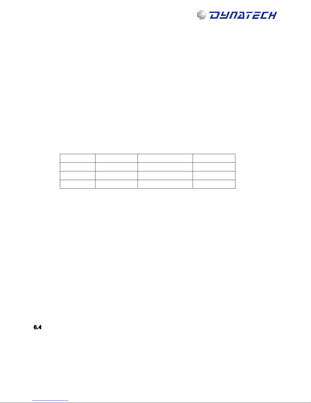
Below is a table of recommended voltages.
Over-excitation Voltage during travel Voltage at floor
24 30 20 12
48 60 40 30
190 215-205* 150 104
* This is the voltage at the rectifier output, which can vary between the values shown.
- To ensure proper operation of the device, it is advisable to design a circuit such that, if the inductive
sensor does not detect the anti-creep system unlocking, the controller will try more than once to supply
current to the coil (the Dynatech D-Box makes 7 attempts before the error message appears that no
reading for the control sensor is detected).
Thus, if there is any mechanical fault preventing the sensor from being read, the same attempts to solve
the problem will be made before an error message appears on the controller.
- To prevent the car from stopping due to the loss of the control sensor signal while travelling, it makes a
reading only at the floors.
- In the event of a cut in the electricity supply to the electric magnet coil when the car is moving, the
speed governor will lock and the safety gear subsequently engaged.
The installation of an autonomous power system is recommended to avoid undesired engagement in the
event of a cut in the mains electricity supply.
- Open the pin to enable the speed governor to turn for automatic rescue. If the pin is not released, the
governor will lock and the safety gear will engage during the rescue movement.
- Use in installations with re-levelling over 20 mm: in installations with re-levelling over 20 mm, certified
switching must be used to activate the electric magnet during the re-levelling process because if it relevels by more than 20 mm then the governor could lock and the safety gear engage. In this case, the
switching must discriminate between re-levelling and an uncontrolled movement.
- Use in installations with door pre-opening: in installations with door pre-opening, certified switching
must be used to ensure the electric magnet remains activated during the pre-opening process because if
the electric magnet does not remain activated then the governor could lock and the safety gear engage.
In this case, the switching must discriminate between pre-opening and an uncontrolled movement.
ANTI-CREEP SYSTEM MAINTENANCE
It is very important that the anti-creep system is in the best possible condition. As it is a mechanism that will perform
many cycles over its lifetime, it is advisable to check its condition and operation during lift maintenance.
The anti-creep system should be kept as free of dust and dirt as possible, to ensure the moving parts are not
obstructed. It should be checked and cleaned of dirt if necessary. After cleaning, a lubricant should be applied to
increase the mechanism life.
The parking system has a translation movement. This movement should be as smooth as possible. For this purpose,
the nylon screw (1) rests on the solenoid edge.
Note: This manual displays partial information on the instructions for use and maintenance of this product. Please refer to the customer
area in Dynatech’s website in order to consult the full manual; http://customers.dynatech-elevation.com/
Page 11

INSTRUCTIONS: QUASAR Cod: DYN 48.1.07
Fecha: 04/12/2017 Revisión: 07
8
Manually check that the system slides smoothly. If necessary, re-tighten the nylon screw so that it rests on the metallic
edge of the solenoid.
7 TECHNICAL FEATURES
Machine: Overspeed governor
Model: QUASAR
Manufacturing company:
DYNATECH, DYNAMICS & TECHNOLOGY, S.L.
Range of use:
Maximum rated speed: 2.18 m/s
Maximum tripping speed: 2.63 m/s
Minimum rated speed: 0.1 m/s
Minimum tripping speed: 0.3 m/s
From 0.3 to 0.69 m/s, the Governor is UNIDIRECTIONAL
From 0.7 to 2.33 m/s, the Governor is BIDIRECTIONAL or UNIDIRECTIONAL
Rope:
6.5 mm Gustav Wolf PAWO 819W
6 and 6.5 mm Drako 250 T
Rope pre-tensioning:
500 N (per branch)
Tension on the rope to be interlocked:
Above 300 N
Pulley diameter: 120 mm
Overspeed contact.
Other features:
Possibility to assemble several devices.
Remote operation
Anti-creep system to comply with UCM
Test pulley
Cover
Safety gears with which it may be used:
All the safety gears with a tripping speed that may be reached by the overspeed governor.
8 INSTRUCTIONS FOR USE AND MAINTENANCE.
To prevent unnecessary risks that may cause the incorrect operation of the governor, two essential criteria must be
considered: Cleaning and monitoring against corrosion. There are mobile elements in any governor that will perform
the interlocking operation. Dirt accumulation in these elements may cause malfunctioning. It is essential that both the
installer and maintenance make sure that these components are perfectly clean.
On the other hand, Dynatech governors have anti-corrosion protection in all the cases; however, it is important that
maintenance checks if there is a corrosion process that may affect any mobile part of the component and may prevent
its natural movement. This will be checked via visual inspection of the surfaces’ condition and acting consequently.
The frequency of these check-ups is left up to maintenance’s criterion; however, they must be more frequent in case
the installation is in an especially corrosive environment.
Note: This manual displays partial information on the instructions for use and maintenance of this product. Please refer to the customer
area in Dynatech’s website in order to consult the full manual; http://customers.dynatech-elevation.com/
Page 12

INSTRUCTIONS: QUASAR Cod: DYN 48.1.07
Fecha: 04/12/2017 Revisión: 07
9
Dynatech cannot be held responsible for any problem or accident arising from the non-compliance of the orders and
recommendations mentioned both in these instructions and in the documents concerning the EC type examination
certificates.
STORAGE AND SERVICE LIFE
The overspeed governor must be stored in a cool, dry place. It must be protected from excessive light and never be
exposed to the open air.
Storage temperature: 5 - 40ºC.
Storage Humidity: 15 - 85% without condensation
Overspeed governor packages should be clean and dry so that they can be clearly identified.
Constantly leaning an unbalanced load on packages, which may cause bending, or the accumulation of products
stacked on top of each other is not allowed. When placing products or product packages on top of each other, the
storage height should correspond to the packages’ load and stability.
If the established criteria of this manual are observed, the overspeed governor’s service life is set by the wear of his
main pulley groove, which depends on the installation duty cycle. When estimating the element’s service life, the
effects of grease, dust or dirt due to the shaft’s condition or to environmental conditions differing from those stated in
this manual, were not taken into consideration
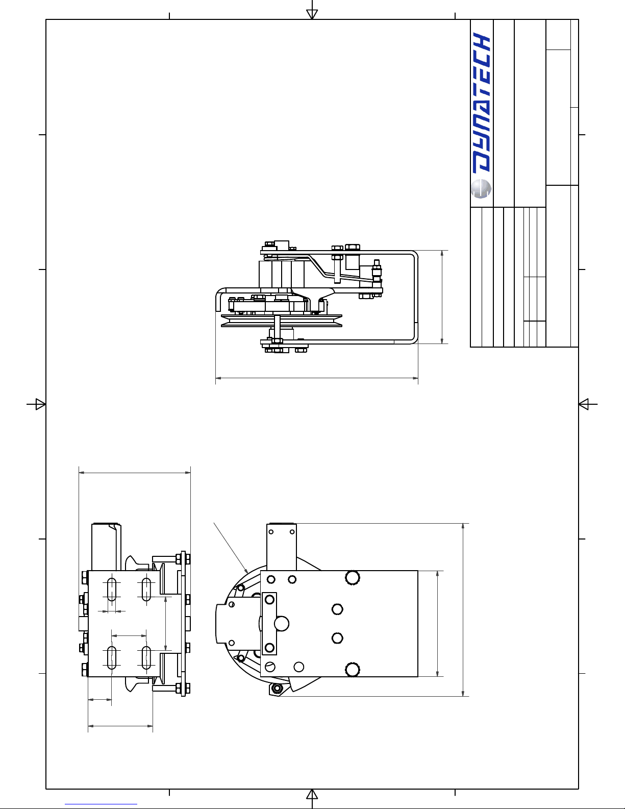
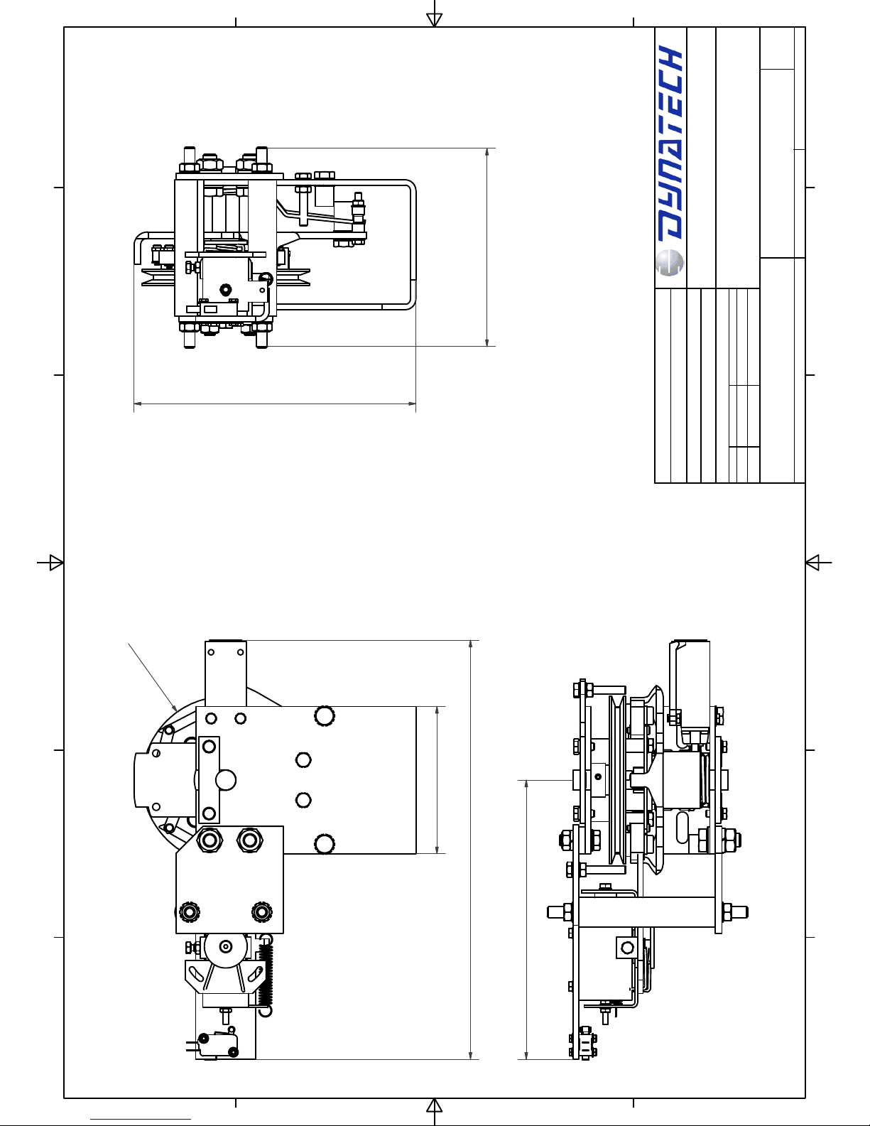
9 QUASAR GOVERNOR’S GENERAL DIMENSIONS
Note: This manual displays partial information on the instructions for use and maintenance of this product. Please refer to the customer
area in Dynatech’s website in order to consult the full manual; http://customers.dynatech-elevation.com/
Page 13
1
1
2
2
3
3
4
4
5
5
6
6
A A
B B
C C
D D
MEDIDAS SIN TOLERANCIA SEGÚN DIN-7168 GM
PLANO COD. Nº:
Quasar Measures
Escala:
Quasar
CONJUNTO:
Sustituye a:
Sustituido por:
DYN 48.C002.00
OBSERVACIONES:
Material:
Peso terminado:
Tto. tco:
Tto. sup:
Fichero:
Fecha
Nombre
Dibujado
Norma
16/03/2015
V.Navaz
CANTIDAD POR CONJUNTO:
3
6
6
7
1
1
6
180
110
12
5
2
1
0
,
5
8
,
5
56
2
4
,
5
97
Page 14
1
1
2
2
3
3
4
4
5
5
6
6
A A
B B
C C
D D
MEDIDAS SIN TOLERANCIA SEGÚN DIN-7168 GM
PLANO COD. Nº:
Quasar A3 measures
Escala:
Quasar
CONJUNTO:
Sustituye a:
Sustituido por:
DYN 48.C003.00
OBSERVACIONES:
Material:
Peso terminado:
Tto. tco:
Tto. sup:
Fichero:
Fecha
Nombre
Dibujado
Norma
16/03/2015
V.Navaz
CANTIDAD POR CONJUNTO:
313
110
1
2
5
2
1
0
,
5
148
208,5
 Loading...