

Page 1
PROFESSIONAL POWER AMPLIFIERS
MP SERIES
MP- 400 0 MP-5 00 0 MP -7 00 0 ( 3U MO DE L)
MP- 300 0 (2 U MO D EL )
OWNER`S MANUAL
0
MP - 400 0
0
MP - 500 0
0
MP - 700 0
PROFESSI ONAL AMPLIFIER
PROFESSI ONAL AMPLIFIERPROFESSI ONAL AMPLIFIER
PROFESSI ONAL AMPLIFIER
PROFESSI ONAL AMPLIFIER
Page 2

Important Precautions
Thi s symbo l is used t o alert t he o pe rato r to foll ow impo rtant o pe ra ti ng
pro cedur es and pr ecaut io ns d et ailed
in do cumen tatio n.
Thi s symbo l is used t o warn op erator s that un insul ated "d an ge ro us volt age s" are pr esent w ithin t he e qu ip men t enclo sure th at m ay p os e a risk
of el ectri c shock .
1.Save t he cart on and pack ing mater ial
even if th e equip ment has ar rived in
good con ditio n. Should y ou ever nee d
to ship th e unit, u se only the o riginal
factor y packi ng.
2.Read a ll docu mentati on before o per ating yo ur equi pment. Re tain all do c umenta tion fo r future re ference .
3.Foll ow all in structi ons print ed on uni t
chassi s for pro per opera tion.
4.Do not s pill wa ter or othe r liquids
into or on t he unit , or operat e the unit
while st andin g in liquid .
5.Make s ure pow er outlet s conform t o
the powe r requi rements l isted on th e
back of th e unit.
6.Do not u se the un it if the ele ctrical
power co rd is fra yed or brok en. The
power su pply co rds shoul d be routed s o
that the y are not l ikely to be w alked on
or pinch ed by ite ms placed u pon or
agains t them, p aying par ticular a tten tion to co rds and p lugs, con venienc e
recept acles , and the poi nt where th ey
exit fro m the app liance.
7.Alwa ys oper ate the uni t with the AC
ground w ire con nected to t he electr i cal syst em grou nd. Preca utions sh ould
be taken s o that th e means of gr ound ing of a pie ce of equ ipment is n ot
defeat ed.
8.Main s volta ge must be co rrect and
the same a s that pr inted on th e rear
of the uni t. Dama ge caused b y connec tion to im prope r AC vo ltage i s not cov ered by an y warra nty.
9.Have g ain con trols on am plifier s
turned d own dur ing power-u p to p re vent spe aker da mage if the re are high
signal l evels a t the input s.
10.Pow er down & d isconne ct units fr om
mains vo ltage b efore mak ing conne c tions.
11.Do n ot turn t he power sw itch on the
"ON" p os ition i f you do not us e it.
12.Do no t use the u nit near st oves, hea t
regist ers, ra diators , or other he at
produc ing dev ices.
13.Do no t block f an intake o r exhaust
ports. D o not ope rate equi pment on a
surfac e or in an en vironme nt which
may impe de the no rmal flow o f air
around t he unit , such as a bed , rug,
weathe rshee t, carpet , or comple tely
enclos ed rack . If the unit i s used in an
extrem ely dus ty or smoky e nviron ment, th e unit sh ould be per iodical ly
"blown f ree" of f oreign ma tter.
14.Do no t remov e the cover. R emoving
the cove r will ex pose you to p otentia lly
danger ous vol tages. Ther e are no user
servic eable p arts insi de.
15.Con necti ng amplif ier outpu ts to
oscill oscop es or other t est equip ment
while th e ampli fier is in br idged mod e
may dama ge both t he amplif ier and tes t
equipm ent!
16.Do no t drive t he inputs w ith a signa l
level gr eater t han that re quired to
drive eq uipme nt to full ou tput.
17.Do no t conne ct the inpu ts / output s
of ampli fiers o r console s to any othe r
voltag e sourc e, such as a ba ttery,
mains so urce, o r power sup ply, regard less of wh ether t he amplif ier or cons ole
is turne d on or off.
18.Do no t run the o utput of an y amplifi er chann el back i nto anoth er chan nel's in put. Do n ot parall el- or
series -conn ect an ampl ifier out put
with any o ther am plifier o utput.
19.Do no t groun d any red ("h ot") term inal.
Never co nnect a " hot" (red ) output to
ground o r to anot her "hot" ( red) outp ut!
20.Non-use perio ds . The power cord o f
equipment should b e un pl ug ge d fr om
the outlet when left u nu se d fo r a lo ng
period of time.
21.Service Infor ma ti on E qu ip me nt
should be serviced b y qu al if ie d se rv ic e
personnel when:
A.The power supply cord or th e pl ug
has been damaged;
B.Objects have fal le n, o r li qu id h as
been spilled into th e eq ui pm en t;
C.The equipment ha s be en e xp os ed
rain;
D.The equipment do es n ot a pp ea r to
operate normally, or exhibits a
marked change in per fo rm an ce ;
E.The equipment ha s be en d ro pp ed ,
or the enclosure dam ag ed .
22.To ob ta in s ervice, contact your neares t
dealer.
Page 1
PR OF ESS IO NA L P OW ER A MPL IF IER S
Important Precautions
MP SERIES
MP- 400 0 MP-5 00 0 MP -7 00 0 ( 3U MO DE L)
MP- 300 0 (2 U MO DEL )
Page 3

Page 2
Table of Contents
1.Front Views & Rear Views
2.Introduction
3.Unpacking
4.Installation and Mounting
5.Front Panel
6.Rear Panel
7.Operation
8.Mode Selection
9.Protection
10.Specifications
3
4
4
4
5
6
8
9
13
15
Page
Table of Contents
Please check up the environment AC POWER supply for
the amplifier before installation and use. Mains voltage
must be correct and the same as that printed on the rear
of the unit. Damage caused by connection to improper AC
voltage is not covered by any warranty.
WARNING
PR OF ESS IO NA L P OW ER A MPL IF IER S
MP SERIES
MP- 400 0 MP-5 00 0 MP -7 00 0 ( 3U MO DE L)
MP- 300 0 (2 U MO DEL )
Page 4
Page 3
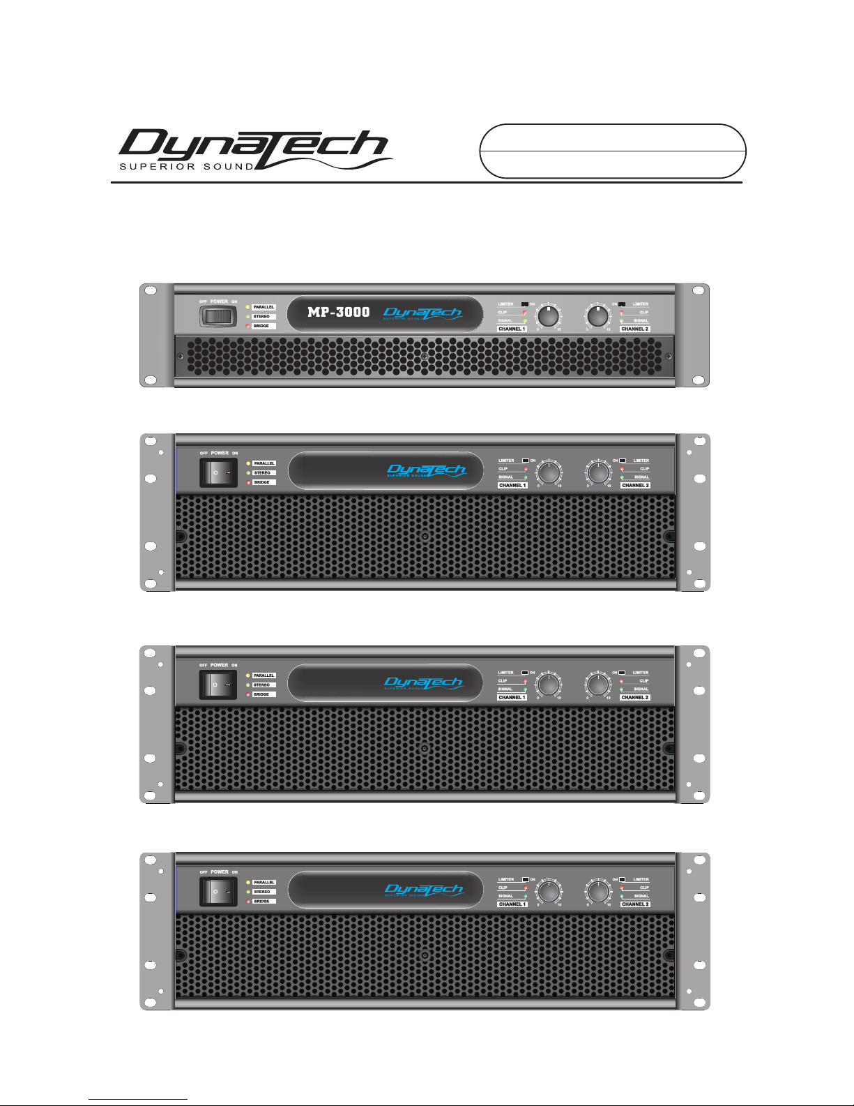
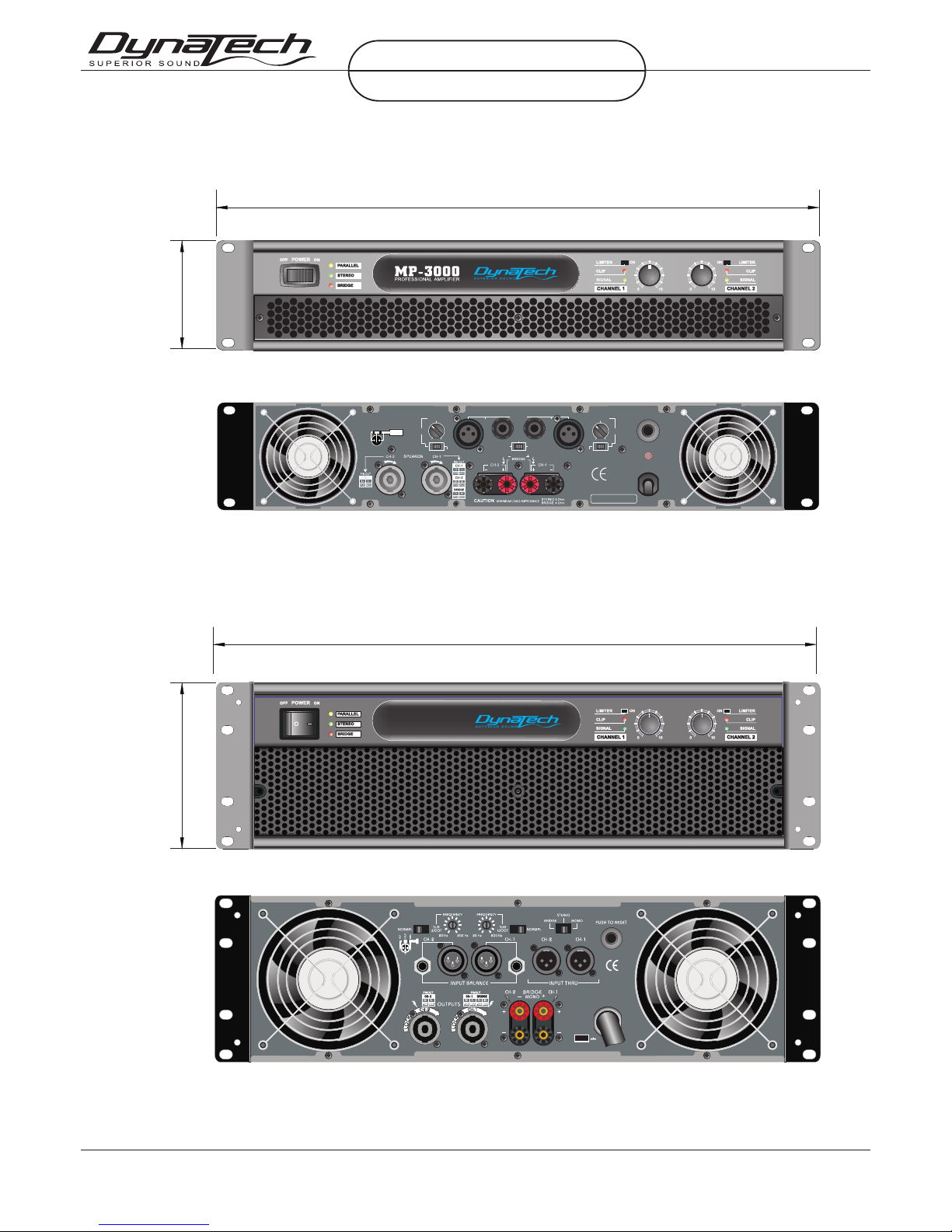
Front Views & Rear Views
MP-4000 & MP-5000 & MP-7000(3U MODEL) Front & Rear View
Fron t
heig ht
5.25 in ch
133m m
Fron t wi dth 19i nc h 483mm
MP-3000(2U MODEL) Front & Rear View
Fron t wi dth 19i nc h 483mm
Fron t
heig ht
3.5i nc h
89mm
dept h 46 5mm
dept h 37 0mm
0
PR OF ESS IO NA L P OW ER A MPL IF IER S
MP SERIES
MP- 400 0 MP-5 00 0 MP -7 00 0 ( 3U MO DE L)
MP- 300 0 (2 U MO DEL )
MP - 70 0 0
PROFESSIO NAL AMPLIFIER
~220VAC 50Hz
1800 WATTS
NORMAL
20Hz 200Hz
SUB
WOOF
FREQUENCY
INPUT
BAL.
2
1
NORMAL
SUB
WOOF
FREQUENCY
POWER AMPLIFIER
20Hz 200Hz
12
3
HOT
COLD
GND
PARALLEL
STEREO
BRIDGE
Serial No.:
O
T
R
S
E
S
S
E
E
R
T
P
PUSH TO RESET
GROUND
LIFT
CAUTION: MINIMUM LOAD IMPEDANCE 2 OHM PER CHANNEL, 4 OHM BRIDGE
O
T
R
S
E
S
S
E
E
R
T
P
Page 5

Introduction
Page 4
Introduction
Congrat ulations on your purchase of a ne w MP Series professiona l power amplifier, and thank you for your
confide nce in DynaTech products.
For your safety, plea se read the Important Precaut ions section before in sta lling and opera tin g the amplifier.
The DynaTech MP Serie s is based on the same adv anced circuit topologie s that have made DynaTech amp lifiers
the choic e of touring professio nal s worldwide. MP Se ries amplifie rs are de signed for high operat ing e fficiency
and accur ate sonic performa nce across the full audi o ban dwidth, even un der stressfu l conditions. Inte rnal components a re the fi nest availabl e, an d key sub-assem bli es are pre- tested before final as sem bly. Finall y, each amplifier is "bur ned i n" and thoroughly test ed (u sing precision audio t est equipment) bef ore shi pping. In addition ,
all MP Series amplifiers in corporate Dyn aTech’s exclusive Tour Class protection featu re s to sa feguard both in ternal circui try a nd connected lo uds peakers. This proven combin ation of advanced de sign, quality cons truction,
and compreh ens ive circuit protection is you r gu ara ntee of fail-sa fe reli ability. You can depe nd on consistent,
stable pe rformance even whe n your MP Series ampli fie r is s ubj ected to punish ing extremes in the most dema n
ding fixe d or mobi le sound reinforcement appl ications.
Please in spect the amplifie r ca reful ly immediately aft er unpa cking. If you fin d any d amage, notify y our
supplie r/dealer immediate ly. Only the shipp er may fi le a damage claim with t he carrier for damage incurred
during sh ipping. Be sure to save the car ton and all packi ng ma terials for the carrie r's inspection. If y our
packing m aterials are in good con dit ion, please sav e the m. If you ever need to ship th e unit back to DynaTech
or an authorized s ervice center, you should u se only the original f actory packing.
Unpacking
Only one MP Series amplifie rs are 2- rack-space un its : MP-3000 and MP- 400 0/MP-5000/M P-7000 are 3rack-sp aces high. All mou nt in standard 19-in ch racks. Four front-panel mo unt ing holes are provided on
each ampl ifier. Rea r mo unting ears give add itional support, a nd use of rear sup ports is highly recomm ended in all mo bile and touring sou nd systems. Option al rack-mount hand les are a vailable.
Installation and Mounting
PR OF ESS IO NA L P OW ER A MPL IF IER S
MP SERIES
MP- 400 0 MP-5 00 0 MP -7 00 0 ( 3U MO DE L)
MP- 300 0 (2 U MO DEL )
Page 6

Page 5
Front Panel
1. Rack Mou nting Ears.
Two front panel mountin g holes are prov ided on each moun tin g ear.
2. AC Pow er Swit ch.
MP Seri es amplifiers have a f ro nt- panel main AC powe r sw itc h .
3. Mode Ind icated LED.
Yellow LED ind icates `parallel ` Mode, Green LED indica tes `stereo` Mode, Red LED in dicates `bridge`
Mode.
4. DynaTech Logo a nd Mo del No.
MP seri es have 4 type model MP- 4000/MP-500 0/M P7000 (3U model ) /MP -3000(2U mode l).
5. Fan Inle t Grills and Filter.
MP Seri es amplifiers are cool ed by t wo rear-mou nte d fans. Cool air from front grills are filte red and f lows
over the heat s ink s and exhausts to back s ide . Make sure these outl ets rem ain clear to allow unrestrict ed
air flow.
6. Limite r Sw itc h
You can select l imiter on `on` for limiter working, an d another mode is for limiter no working .
7. Input Attenuators.
Two input attenu ato rs adjust level f or thei r respect ive a mplifier channels. I n Bridged &Mono(pa rallel)
Mode.
8. Clip LED .
Illumin ates at the clipping t hresh old. Continuo us il lumination al so in dicates that ACL (Active Clip
Limitin g) prot ection circuitry is en gaged.
9. Signal L ED.
Illumin ates to indicate tha t a signal (above a mini mum threshold) is present at th e amp lifier input, and that
the signa l is being amplified .
1
2
3
4
5
6 7 8 9
1
2
3
4
5
6 7 8 9
Front Panel
0
PR OF ESS IO NA L P OW ER A MPL IF IER S
MP SERIES
MP- 400 0 MP-5 00 0 MP -7 00 0 ( 3U MO DE L)
MP- 300 0 (2 U MO DEL )
MP - 70 0 0
PROFESSIO NAL AMPLIFIER
Page 7

GROUND
LIFT
CAUTION: MINIMUM LOAD IMPEDANCE 2 OHM PER CHANNEL, 4 OHM BRIDGE
O
T
R
S
E
S
S
E
E
R
T
P
~220VAC 50Hz
1800 WATTS
NORMAL
20Hz 200Hz
SUB
WOOF
FREQUENCY
INPUT
BAL.
2
1
NORMAL
SUB
WOOF
FREQUENCY
POWER AMPLIFIER
20Hz 200Hz
12
3
HOT
COLD
GND
PARALLEL
STEREO
BRIDGE
Serial No.:
O
T
R
S
E
S
S
E
E
R
T
P
PUSH TO RESET
Page 6
Rear Panel
Rear Panel
10 1511
14
12 1613
18 19 20
16
12
18 19
20
11
10. Fan Out let Ports
Cooling a ir ente rs the amplifie r through the fron t gri lls and exhaust s throu gh th e fans. Be sure not to
block the se ports when instal ling the amplifier or other associat ed equipment. Air mu st fl ow unimpeded
through these po rts.
11-13 .Balanced 1/4" (TR S) & XLR Input Connect ors.
These con nectors accept inp ut signals on balanc ed TRS an d XLR input plugs.
See the fig ure at th e right for informatio n on po larity. Con nec tors for each channel are in para lle l; the unused con nec tors may be used fo r "loop t hroug h" connection t o other amplifiers.
NOTE.' Un balanced "Ti p/Sleeve" plu gs may be used with the ba lanced TRS
"Ti p/Ring/Slee ve" connectors. Th e "ring" terminal or n egative input w ill b e
connect ed to ground interna lly. When using th ree-pole ('st ere o ')TRS connectors, mak e sure that the ring con nection is made eith er to the cold (-) ou tpu t of
the sourc e equipment, or to gro und. Incorrect con nections may ca use a 6 dB loss
in level.
14-15.S UBWOOF fi lter freq uen cy and select swi tch M P-Series 3U mod el ha ve `SUBWOOF` fi lter
functio n, Subwoof switch on ` SUBWOOF` positio n , SUBWOOF is wor king. You can adjust ` SUB WOOF`
filter frequency. P ush the switch on ` NOR MAL` pos-tion ,Th e amplifier works on nor mal full audio
frequency s tat us without subwoof f ilter.
NOTE! SUB WOO F FU NCTION IS ONLY FOR 3U MODEL MP-4000/ MP-5000/MP-700 0
3. NE GATIVE ( -)
2. PO SITIV E (+)
1. GR OUND ( )
TIP PO SITIV E (+)
RIN G NEGATI VE (-)
SLE EVE GRO UND ( )
12 3 21 3
PR OF ESS IO NA L P OW ER A MPL IF IER S
MP SERIES
MP- 400 0 MP-5 00 0 MP -7 00 0 ( 3U MO DE L)
MP- 300 0 (2 U MO DEL )
10
15
1717
17
Page 8

Page 7
Rear Panel
16. Mode Se lection Switch.
This recessed, three-po sition switch conf igure s the amplifier for Stereo, Parallel o r Br idg ed Mode operation. Amplifiers are facto ry- configured for Stereo Mode. See s ect ion on Mode Selec tio n for more in formation.
17.Circui t Break er .
MP Seri es amplifiers have a c ircui t breaker. The circuit brea ker shu ts of f during normal u se, P lease
switchi ng off the AC power switch fo r a mi nut e, Then t urn on the AC pow er swit ch ag ain ,Push the circuit
breaker to reset the power. If the circuit breaker shu ts of f immediately , The a mplifier needs servi cing.
18-19.O utput Connectors ( Two v ersions, mark et de pendent).
MP Seri es amplifiers are supp lie d with either Binding Po sts or Sp eakon connectors . Connection to the
binding p osts can be made with ba re wire, ba nan a plugs, or spade lug term ina tions. Make con nections to both
the termi nals of Channel 1 and Ch annel 2 for Stereo or Parallel Mode, or a sing le co nnection across the red
("hot") terminals only of Ch annels 1 and 2 for Bridged M ono M ode. Using Spea kon -type speaker cables , mak e
connect ions to the "+1"and "- 1" terminals of Chan nel 1 and Channel 2 conn ectors for Stereo or Parallel Mode,
To the Bridged mod e con nector to the "+1"and "+ 2" terminals of Chan nel 1. See section on Mo de Selection
for more informati on.
20.AC POW ER Cord .
Connet to AC power supply. Be sure that tha t the supplied volfa ge in your area ma tches the ampli fiers
required voltage .
Configuring the Low C ut Filter:
Activ ating Low Cut Filter s 〞Dip switches 1 and 4 act ivate and deactiva te the Low Cut Filter. Channe l 1 filters
is controll ed by d ip switch 1 and cha nne l 2 filter is controlled by dip swi tch 4.
Low Cut Frequenc y Selector 〞When the Low Cu t Fil ter is activated, dip sw itches 2 for channel 1 and 3 f or
channel 2 w ill control the frequency roll-off . Wh en di p switches 2 and 3 are in the "O N" th e filter will cut off
frequenci es at a nd below 30Hz, wh en th ese dip switche s are in th e "OF F" position the f ilter will cut off
frequenci es at a nd below 50Hz. Pl eas e note: Each chan nel o perates indep end ently of each oth er allo wing each
channel t o have different filte r setti ngs .
1 2 3 4
OFF
ON
ch.1 ch.2
ch.2 ch.2
1. low cut (o n/off)
2. On=30H z, off=50Hz
3. On=30H z, off=50Hz
4. low cut (o n/off)
NOTE: Thru-
Thru will a llow the user to daisy -chain one ampl ifi ers signal inpu t int o another ampli fie r. Plug the sig nal s ource
outputs i nto the first amplif ier's input, patch f rom t he amplifier's THR U jac ks to the next ampl ifier's input, and so
on, daisy -chaining as many am plifiers as there is n o excessive lev el lo ss. Is not affected by cro ssover setting.
PR OF ESS IO NA L P OW ER A MPL IF IER S
MP SERIES
MP- 400 0 MP-5 00 0 MP -7 00 0 ( 3U MO DE L)
MP- 300 0 (2 U MO DEL )
Page 9

Page 8
Operation
MP Seri es amplifier power requirements are rated at:
a) "idle"
b) 1/8th po wer ("t ypical" music c ond itions)
c) 1/3rd po wer ("c ontinuous" music c onditions)
d.) maxim um rated power ( under limited) .
The maxim um power curre nt draw rating is l imi ted only by the rear circuit breaker(3U MO DEL) or the fuse
type (2U MO DEL) . Consult the spe cifications sect ion for figure s on the current that each a mplifier will
demand. M ake sure the mains volta ge is c orrec t and is the same as th at pr inted on the rear of the ampli fie r.
Damage ca used by connecting t he amplifier to improper AC vol tag e is not covered by any warr ant y.
Unless ot herwise specifie d when ordered, DynaTech amplifi ers shipped to custo mers are configured
as follow s:
North America 120VAC / 60Hz
Europe 230VAC / 50Hz
Asia 220VAC / 50H z
Austral asia 240VAC / 50Hz
South America 120VAC / 60Hz or 220 VAC / 50 Hz
Japan 100 VAC / 50Hz
NOTE: Always turn off and dis connect the amplif ier from mains volta ge before makin g aud io connection s.
Also, as an e xtra precaution, h ave the attenua tor s turned down during p ower-up.
Operation
Connecting Power / Circuit Size Requirements.
Cooling System and Requirements.
Use eithe r th e XLR o r 1/ 4-i nch input conne cto rs on the rear to supply audio sign als to your DynaTech MP
Series am plifier. Both connector s accept balanced an d unbalanced audio c onnections. (The M P Series
amplifi ers are c onfigured standard w ith " Pin 2 hot" on XLR inp uts . Please note tha t som e other Audio
amplifi ers are c onfigured with "Pin 3 ho t") . Th e unused connector can be use d to jumper the audio inpu t
to anothe r am pli fier in put.
Connecting Inputs.
Speaker s are con nected using Ou tpu t Binding Posts o r Speak on co nnectors, For more informat ion, see the
Mode Sele ction sections.
Connecting Outputs.
Connect ing amplifier o utp uts to oscillos cop es or other test eq uip ment while the
amplifi er is in bridged mo de ma y damage both the a mpl ifier and test eq uip ment!
MP Seri es amplifiers use a tw in-tunnel forced-a ir cool ing system to mainta in a low, even opera ting temperature. Drawn o ut by d ual 45 cubic feet -pe r-minut e (CFM) fans on the rear panel, air flows from the fron t gri ll
and through the co oling fins of the chan nel heat sinks (diss ipating power transi sto r he at), then exhausts t hrough the ba ck panel ports. The "intell igent" variab le- speed DC fans are controlled by h eat sink temperatu re
sensing c ircui ts. Whe n the amplifier is turne d on, the fans briefly " re v up, " then slow to an idle; th is indicates
that the te mperature sensing ci rcuit s are ope rating normally. The fa n speed increases only a s requi red by
heat sink t emperatures, keepi ng fa n noise to a minimu m. Un der ext re me thermal load, the f ans will force a
very larg e volume of air through the heat si nks . If either heat sink surp asses the maximum al lowed temperature, the se nsi ng circ uit will shut dow n the o utput, no signa l out put to the load . If th e pow er tran sformer
overhea ts, another sensing ci rcuit s hut d own both channe l out put until the tra nsf ormer cools to a safe temp erature.
IMPORTANT: To ens ure o ptimum coolin g, periodically cl ean the amplifi er fa n filters. Also make certa in th at
there is en ough space around th e back of the amplifie r to allow the cool ing a ir to escape. If th e amp lifier
s rack-mo unted, do not use door s or covers on the front o f the rack, the exhaus t air must flow out with out
resista nce. If the amplifie rs are to be housed in rac ks with closed ba cks , allow at least on e (1) s tandard rack
space of op ening in the front of th e rack for every four am plifiers.
PR OF ESS IO NA L P OW ER A MPL IF IER S
MP SERIES
MP- 400 0 MP-5 00 0 MP -7 00 0 ( 3U MO DE L)
MP- 300 0 (2 U MO DEL )
Page 10

Mode Selection
Page 9
The three-positi on, rec essed Mode Select sw itch (located on the rea r panel ) con figures the amplifie r fo r
either Stereo, Par allel or Bridged Mono Mo de. Amplifiers a re fact ory -configured for Stereo Mode.
Stereo Mode.
In Stereo Mod e, bo th channels operat e independent ly, with their input atte nua tors controlling the ir
respectiv e lev els. Signal at Ch ann el 1's input produces ou tpu t at Channel 1's ou tpu t, while signal a t
Channel 2 's input produces output at C hannel 2's output. R ecommended minim um nominal load
impedan ce for st ereo op eration is 2 ohms p er chan nel. Either the 1/4" (TR S) in puts or the XLR inputs
may be used .
Parallel (Mono)Mode.
When set to Par all el(Mono) Mode , Th e sig nal input to Chan nel 1 a nd channel 2 will b e add ed together
and be ampl ified and appear at outputs f or both C hannels 1 & 2. The output si gna l is controlled by each
attenua tor
NOTE!: So me other amplifier s only use Channel 1 for i nput, and both outpu t is controlled b y Cha nnel
1 attenua tor .
Bridged Mono Mode.
Bridged M ono Mode straps both a mplifier channels to get her to make a very powerfu l, single-channe l
monaura l amplifier. One channel "p ush es" and the other "pulls " equally, doubl ing the power over that of
either chan nel a lone. Signal is a ppl ied to the Channe l 1 inp ut only, both o utp ut level is controlled b y Cha nnel 1`s att enuator .
NOTE: The c hannel 2 input conne ctors (XLR and/or TR S) may be used to "lo op th ru" the channel 1 s ign al
when in par allel or bridged mon o mode.
Use extre me caution when oper ating the ampli fie r in Bridged Mono M ode . Never ground ei the r side of the
speaker c able when the amplif ier is in Bridged M ono M ode; both sides a re "h ot." If an output p atc h panel
is used, al l connections must b e isolated from e ach o ther and from the p ane l. The recommen ded m inimum
nominal l oad impedance i n the B ridged Mono Mod e is 4 oh ms, which is the eq uiv alent to drivin g bot h
channel s separately at 2 ohms . Driving bridged lo ads of less than th e rec ommended mini mum s will activate
the IGM cir cuitry, r esu lting in a loss of po wer, and may also le ad to a thermal protec t condition.
Subwoofer Mode
This mode s ends low frequencies t o you r sp eak ers without the u se of a n external cross-ove r. The subwoof er
operati on can be operated in st ereo, m ono, or bridge mono mode s. Ch ange the different ope rating modes by
flippin g the mode switch on the rea r of the un it to y our desired operating mode. Also, set the subwo ofer mo de
switch to t he subwoofer position. Us e the fre quency select or to adj ust the subwoofer output freq uen cy from
20Hz to 200 Hz. The d ifferent subwoofer modes are li ste d as follows:
Bridge Subwoofer - This op era tion allows you t o get t he most possibl e pow er out of your amplifier for
the sole pu rpose of running a hig h powered subwoofer loudspe ake r in m ono . To avoid am pli fier overheating,
never run the a mpl ifier below 4 ohms in this m ode . In this mode you ma y use t he frequency adjustm ent on
the rear of the amp, to co ntrol t he freq uency output level . Frequ encies may bead jus ted from 20Hz to 200Hz.
Page 12 det ails a typical Bridg e Subwoofer set up.
Stereo Subwoofer - This oper ati on is similar to the Bridg e Subwoofer operatio n but i n stere o. This
operati on allows you to run sev eral subwoofers do wn to a minimum of 2 ohms. To avoid amplif ier ove rheating , never run the amplifie r below 2 o hms i n this mode. Set up t his m ode as you would a st and ard stereo
set up. Be su re both c hannels are set to ※SUBWO OF.§ In this mo de you may use the frequency ad justment
on the rear of the amp, to c ont ro l the bass frequency output l evel. Frequencies ma y be ad justed from 20Hz
to 200Hz. P age 10 details a typic al Stereo Subwoofer set up.
Parallel (Mono) Subwoofer - This opera tio n is similar to the Stereo Sub woo fer ope ration but in mon o.
When runn ing subwoofers it is u sually recommended t o run t hem in mono mode to a chi eve a cleaner tighter
low end. This o per ation allows yo u to ru n several subwo ofe rs down to a minimu m of 2 oh ms. To avoid amp lifier
oveheat ing, never run the ampli fie r be low 2 ohms in this mode. S et up t his mode as you wou ld a st andard stereo
set up. Be su re both c hannels are set to ※SUBWO OF§ an d the mode switch i s set t o ※MONO.§ In this mod e
you may use t he freq uency adjustment o n the rea r of t he amp, to control the bass frequ enc y output level.
Frequenci es ma y be adjusted from 20Hz to 2 00H z.
One Channel Normal/One Channel Subwoofer (BI-AMP) - You may also use your amp to
bi-amp yo ur syst em. You may use one side of the a mp to power a subwoofer and the other side t o pow er a
full rang e speaker.
See figures o n pag es 10 - 12 showing outpu t connection in for mation.
Mode Selection
PR OF ESS IO NA L P OW ER A MPL IF IER S
MP SERIES
MP- 400 0 MP-5 00 0 MP -7 00 0 ( 3U MO DE L)
MP- 300 0 (2 U MO DEL )
Page 11

GROUND
LIFT
CAUTION: MINIMUM LOAD IMPEDANCE 2 OHM PER CHANNEL, 4 OHM BRIDGE
O
T
R
S
E
S
S
E
E
R
T
P
~220VAC 50Hz
1800 WATTS
NORMAL
20Hz 200Hz
SUB
WOOF
FREQUENCY
INPUT
BAL.
2
1
NORMAL
SUB
WOOF
FREQUENCY
POWER AMPLIFIER
20Hz 200Hz
12
3
HOT
COLD
GND
PARALLEL
STEREO
BRIDGE
Serial No.:
O
T
R
S
E
S
S
E
E
R
T
P
PUSH TO RESET
Page 10
Stereo Mode Connections
or
spe ker+
spe ker-
spe ker+
spe ker-
Ch.2
input
or
Ch.1
input
or
inp ut thru
or li nk o ut
Ch. 2 Ch. 1
2-
1+
2+
1-
2-
1+
2+
1-
or
spe ker+
spe ker-
spe ker+
spe ker-
2-
1+
2+
1-
2-
1+
2+
1-
Ch.2 outp ut
spe ker+
spe ker-
spe ker+
spe ker-
Ch.1 outp ut
Ch.2 outp ut
Ch.1 outp ut
spe ker+
spe ker-
Ch.1 outp ut
spe ker+
spe ker-
Ch.2 outp ut
Ch.2 outp ut
Ch.1 outp ut
Mode Selection
normal mo de
subwoof m ode
PR OF ESS IO NA L P OW ER A MPL IF IER S
MP SERIES
MP- 400 0 MP-5 00 0 MP -7 00 0 ( 3U MO DE L)
MP- 300 0 (2 U MO DEL )
Ch.2
input
or
Ch.1
input
or
Page 12

GROUND
LIFT
CAUTION: MINIMUM LOAD IMPEDANCE 2 OHM PER CHANNEL, 4 OHM BRIDGE
O
T
R
S
E
S
S
E
E
R
T
P
Parallel Mode Connections
Page 11
Mode Selection
PR OF ESS IO NA L P OW ER A MPL IF IER S
MP SERIES
MP- 400 0 MP-5 00 0 MP -7 00 0 ( 3U MO DE L)
MP- 300 0 (2 U MO DEL )
~220VAC 50Hz
1800 WATTS
NORMAL
20Hz 200Hz
SUB
WOOF
FREQUENCY
INPUT
BAL.
2
1
NORMAL
SUB
WOOF
FREQUENCY
POWER AMPLIFIER
20Hz 200Hz
12
3
HOT
COLD
GND
PARALLEL
STEREO
BRIDGE
Serial No.:
O
T
R
S
E
S
S
E
E
R
T
P
PUSH TO RESET
or
spe ker+
spe ker-
spe ker+
spe ker-
Ch.1
input
or
inp ut thru
or li nk o ut
Ch. 1
2-
1+
2+
1-
2-
1+
2+
1-
or
spe ker+
spe ker-
spe ker+
spe ker-
2-
1+
2+
1-
2-
1+
2+
1-
Ch.2 outp ut
spe ker+
spe ker-
spe ker+
spe ker-
Ch.1 outp ut
Ch.2 outp ut
Ch.1 outp ut
spe ker+
spe ker-
Ch.1 outp ut
spe ker+
spe ker-
Ch.2 outp ut
Ch.2 outp ut
Ch.1 outp ut
normal mo de
subwoof m ode
Ch.1
input
or
Page 13

GROUND
LIFT
CAUTION: MINIMUM LOAD IMPEDANCE 2 OHM PER CHANNEL, 4 OHM BRIDGE
O
T
R
S
E
S
S
E
E
R
T
P
Bridge Mode Connections
Page 12
Mode Selection
PR OF ESS IO NA L P OW ER A MPL IF IER S
MP SERIES
MP- 400 0 MP-5 00 0 MP -7 00 0 ( 3U MO DE L)
MP- 300 0 (2 U MO DEL )
~220VAC 50Hz
1800 WATTS
NORMAL
20Hz 200Hz
SUB
WOOF
FREQUENCY
INPUT
BAL.
2
1
NORMAL
SUB
WOOF
FREQUENCY
POWER AMPLIFIER
20Hz 200Hz
12
3
HOT
COLD
GND
PARALLEL
STEREO
BRIDGE
Serial No.:
O
T
R
S
E
S
S
E
E
R
T
P
PUSH TO RESET
or
spe ker+
spe ker-
Ch.1
input
or
inp ut thru
or li nk o ut
Ch. 1
2-
1+
2+
1-
or
spe ker+
spe ker-
2-
1+
2+
1-
Bridge ou tput
spe ker+
spe ker-
Bridge ou tput
spe ker+
spe ker-
Bridge ou tput
Bridge ou tput
normal mo de
subwoof m ode
Ch.1
input
or
Page 14

Protection
Page 13
Protection
The MP seri es co mes with a built- in li miter. When th e input signal ov erl oads, the “CLIP LE D’s” indi cate
a signal ov erload, at this time , the master volume shou ld be l owered to reduce distortion . If the input gain leve l
is not reduce d the b uilt-in limit er will a ctivate. During si gnal overload, the l imiter will reduce the input au dio
signal en ough to minimize the a mount of clipping. A limiter takes the g ain o f an overloadin g sig nal and reduces
it, the reduc tio n in gain reduces distor tion that can cause da mag e to your speakers and amp lifier. Du ring
normal op eration below clip ping, and momentar y clips on peaks, the li miter does not affect th e aud io signal
and is inau dible. It will allow b rief clipping o f pea ks and will only activ ate when contin uou s, hard clippin g
occurs. D uring excessive cl ipping the limi ter wil l reduc e the audio signal eno ugh to minimize the am ount of
clippin g. When t he input signal d ecrea ses e nough that clip pin g ends, the limit er will d eactivate and ceas e its
gain reduct ion . Th e lim iter has a fixed threshold a nd ca n not be adjusted.
Limiter
8-Ohm Loa ds: The a mplifier can operate a t pra ctically any po wer lev el without risk o f ove rheating. How eve r,
if it is push ed hard enough to cont inually light the “C LIP” indicator, the ampli fier’s average outpu t pow er
can reach 150 w att s.
4-Ohm Loa ds: If the “CLIP” indi cator flashes occasi ona lly, the ampl ifi er is app ro aching its maximum
long-te rm power capacity. If it is l it about half the t ime , the amplifier channe l will probably go into th erm al
protectio n wit hin a few minutes .
2-Ohm Loa ds: Except for an occasi ona l flash, keep the “ CLI P” indicator dark to avo id ov erheating the
amplifi er chan nel. Clipping s hou ld be kept to a reasonable m ini mum. An ampli fie r’ s peak current draw a t
full outp ut power into 2 ohms is several t imes what the “no rma l” draw is, but its v ari ous pro tection
circuits wi ll prev ent t his condition l ast ing more than a minute or two.
Safe Power Levels at Different Output Loads
The MP seri es am plifiers all co me wi th built-in Out put S hort Circuit Protects. The Outp ut Sh ort
Circuit Protecti on prot ects the output devi ces of the amplifier from short c ircui ts and stressful loads . If yo ur
speaker lin es sh ort, the amplif ier aut oma tically detec ts this problem and discont inues operation fo r th at
channel . If one side of your amplif ier bec ome s shorted and goe s int o protect mode, the othe r si de wi ll continue
to operat e normally. Duri ng short circuit protection , the “Clip” LED will li ght simultaneous ly indicating
amplifi er faul t. The ch annel output du rin g the “Short Circuit Prote cti on” will be inter rup ted (i.e. no soun d
output) S hort Circuit Protection can u sua lly be traced bac k to th e signal output l ine ( i.e. speaker line). Ch eck
the line from t he ou tput terminal o f the a mplifier to the speake r. If thi s lin e good, check the i nte rnal speaker
connect ions and component s. A short ci rcuit w ill u sually be trace d to a ba d cable or a bad speaker compo nen t
and is rarely t rac ed to the amplifi er itse lf.
Short Circuit Protection
Thermal Protection
The input circuits a re isol ated by 10k resistors. An ultrasonic networ k uncouples RF fro m the output and
helps kee p the amplifier stable w ith rea ctive loads.
Input/Output Protection
Dual vari able speed fans on the M P series amplifi er provid e adequate cooling . During low level out put the
fans run at n ormal speeds. Duri ng high output and as he at raises, (exceed ing 50° C), the fans wil l run at
higher spee ds to a id the cooling process . If th e heatsink temp era ture exceeds 91° C, the am plifier will mute
until the a mplifier cools down. When the a mpl ifier cools below 90º C, t he amplifier will return to nor mal
operati ons. Be sure not to operat e you r am pli fier below the minimum l oad ratings to reduce th e ris k of
overhea ting problems.
The AC main volt age is printed on t he ba ck where the AC power input . Con nec ting to the wrong voltag e
is dangerou s and m ay damage the amplif ier. Always be sure the source volta ge fo r yo ur areas match es the
required voltage f or your amplif ier.
Operating Voltage (AC Mains)
PR OF ESS IO NA L P OW ER A MPL IF IER S
MP SERIES
MP- 400 0 MP-5 00 0 MP -7 00 0 ( 3U MO DE L)
MP- 300 0 (2 U MO DEL )
Page 15

Page 14
PR OF ESS IO NA L P OW ER A MPL IF IER S
MP SERIES
MP- 400 0 MP-5 00 0 MP -7 00 0 ( 3U MO DE L)
MP- 300 0 (2 U MO DEL )
MODEL NO. MP-3000 MP-4000 MP-5000 MP-7000
Output Power:
2 ohm ,1 khz 1% THD
4 ohm ,1 khz 1% THD
8 ohm ,1 khz 1% THD
(Bridge Mode, mono)
4 ohm ,1 khz 1% THD
8 ohm ,1 khz 1% THD
1200w RMS Per Ch.
800w RMS Per Ch.
500w RMS Per Ch.
2300w RMS
1700w RMS
1700w RMS Per Ch.
1200w RMS Per Ch.
700w RMS Per Ch.
3000w RMS
2000w RMS
2300w RMS Per Ch.
1600w RMS Per Ch.
1000w RMS Per Ch.
3600w RMS
2500w RMS
3000w RMS Per Ch.
2200w RMS Per Ch.
1400w RMS Per Ch.
6700w RMS
4700w RMS
Totel Harm onoic
Dis tortion:
20Hz~20kHz,@rated
output power, 8 ohm s
Les s than 0.01%
Input Sens itivity and
Impedance:@rated
output power, 8ohns
Dim ens ions & Weight
Hight
Width
Depth
Weight
3.5"(8.8cm)
19"(48.3cm)
14.7"(37.0cm)
31 lbs.(14kgs)
5.25"(13.3cm)
19"(48.3cm)
15.9"(40.5cm)
55 lbs.(25kgs)
5.25"(13.3cm)
19"(48.3cm)
15.9"(40.5cm)
61.7 lbs.(28kgs)
5.25"(13.3cm)
19"(48.3cm)
15.9"(40.5cm)
70.5lbs .(32kgs)
Frequency Res ponse
+/- 1db, 1w RMS, 8ohm s
+/-0.2db, @rated
output, 8 ohm s
Hum &Noise:
Below rated output,
8 ohm s
Power Cons umption:
@rated output power,
8ohms
7.5A@230V AC
(FUSE)
10A@230V AC
(FUSE)
12.5A@230V AC
(FUSE)
17.5A@230V AC
(FUSE)
Cooling System:
2 Dual Speed Fans
and Heats inks
Les s than 0.02%
1.0v RMS(0 dBv)
10Hz - 40kHz
20Hz - 20kHz
100dB, unweighted
Page 16

Sonotone El ec tr on ic s
Tel:+91 -2 2- 26 61 34 99 F ax :+ 91 -2 2- 26 614600
 Loading...