

Dynatech BBM, YBM Additional Maintenance And Repair Instructions
BBM & YBM INSTRUCTIONS [May 2004]
Additional Maintenance
and Repair Instructions
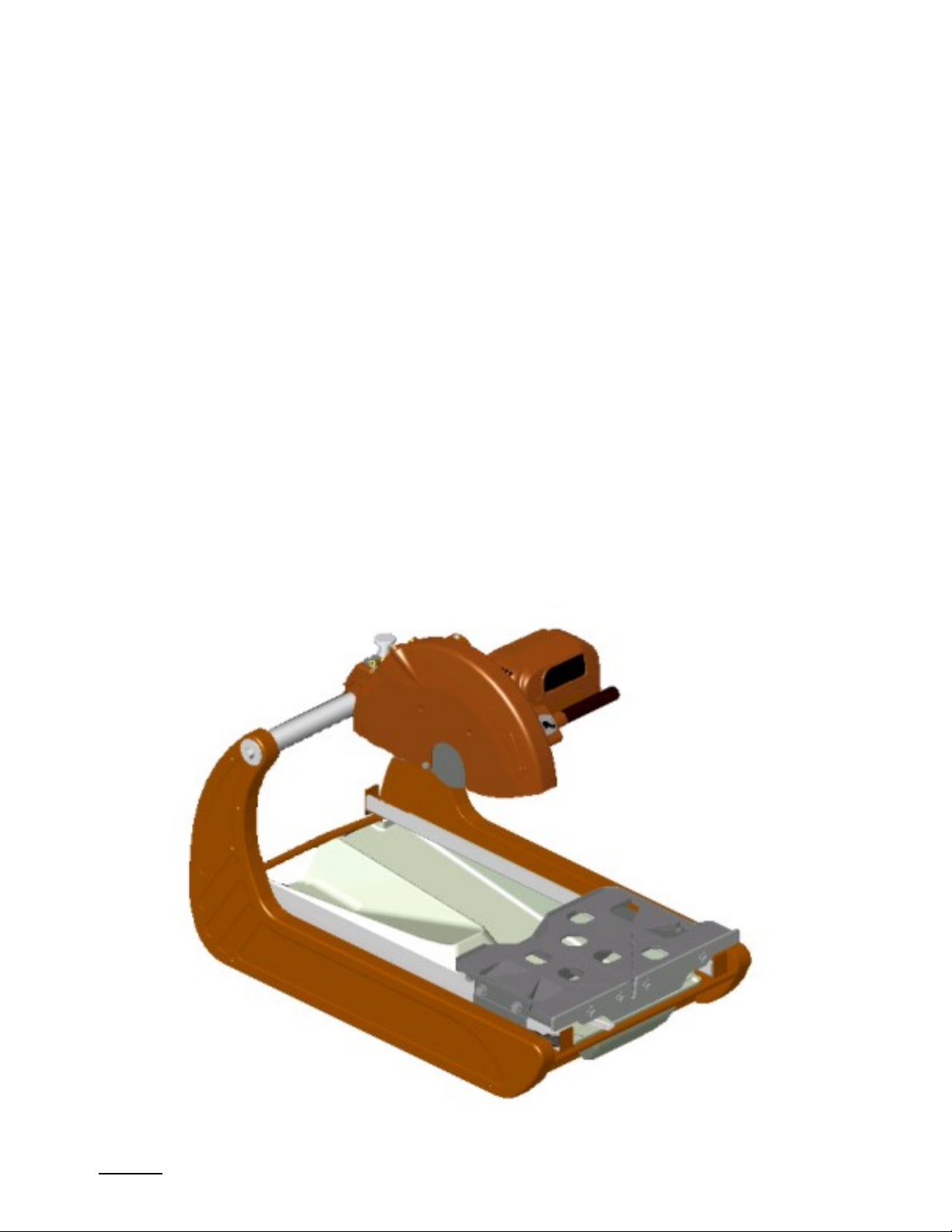
BBM / YBM
Mini Masonry Saw
Issue 1
May 2004
NEVER ATTEMPT ANY OF THE INSTRUCTIONS WITH POWER CONNECTED TO SAW!
BBM & YBM INSTRUCTIONS [May 2004]
DISCONNECT ALL POWER TO THE SAW!
NEVER ATTEMPT ANY OF THE INSTRUCTIONS WITH POWER CONNECTED TO SAW!
Removing the Motor
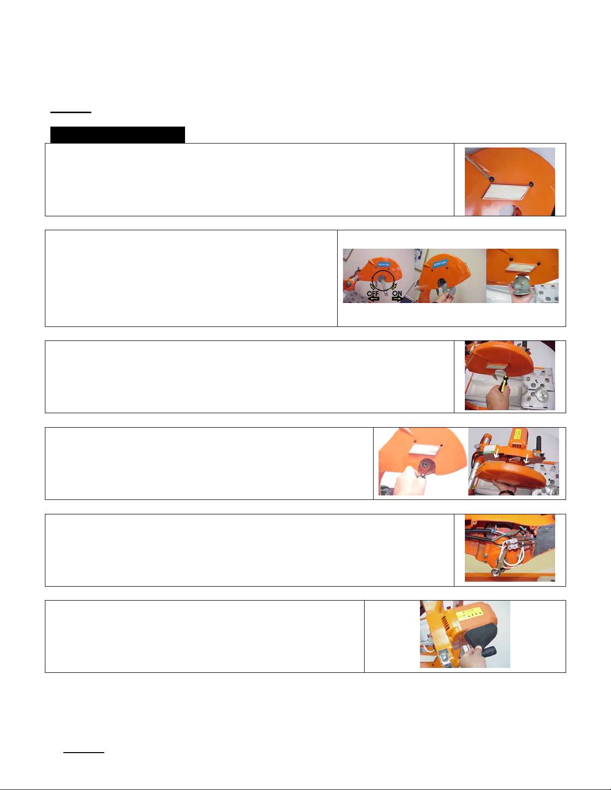
1. Remove the two plastic plugs in the blade guard to expose
the two blade guard mounting screws located under the
blade guard.
2. Using a 17mm wrench, turn the blade shaft
screw clockwise and take the screw and
washer out of the end of the shaft. With the
blade shaft screw and washer removed, pull
both blade flanges outward and off the end of
the blade shaft.
3. Insert a Phillips head screw driver into the blade guard screw
access holes and remove the two screws holding the blade guard
on the cutting head casting.
4. From under the blade guard, remove the two screws
located at the bottom of the blade shaft housing
casting and pull the blade guard outward and off the
blade shaft casting housing.
5. Using a narrow tip slot screw driver remove the two white motor
wires in the terminal block.
6. Remove the air filter.
NEVER ATTEMPT ANY OF THE INSTRUCTIONS WITH POWER CONNECTED TO SAW!
BBM & YBM INSTRUCTIONS [May 2004]
Removing the Motor [Continued]
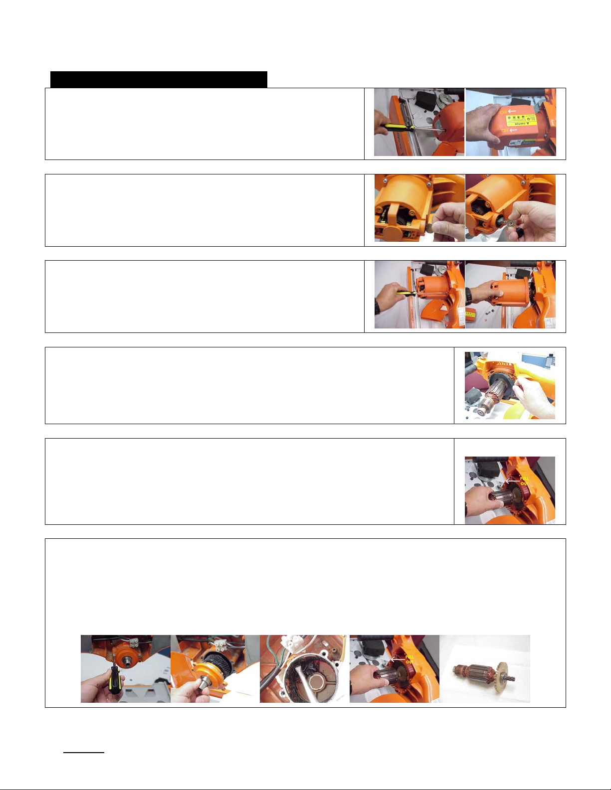
7. Using a Phillips head screw driver, remove the four
screws in the back of the plastic motor air intake
cover and slide the housing outward and off of the
motor housing.
8. Using a coin or a wide blade screw driver, remove
the plastic brush cap and carefully pull the carbon
brush out of the motor housing. Remove brushes
on both sides before attempting to pull the motor
housing off of the armature.
9. Using a Phillips head screw driver, remove the four
screws at the front of the motor housing and
carefully slide the motor housing outward and off
the armature.
10. Pull the plastic motor retaining plate out of the cutting head casting
and off the armature.
11. Grab the armature and pull the armature outward and out of the
motor housing.
If the armature does not pull out of the housing, remove the blade shaft retaining plate assembly
and use a long, wide blade screw driver and rubber mallet to tap the armature out of the cutting
head casting. Make sure to place the screw driver against the end of the armature shaft and
NOT against the radial bearing race or against the cutting head casting. Once the armature is
removed, re-insert the blade shaft retaining plate assembly into the cutting head casting. Align
the ears in the blade shaft retaining plate casting with the holes in the cutting head casting and
then insert two screws in the top ears and tighten.
NEVER ATTEMPT ANY OF THE INSTRUCTIONS WITH POWER CONNECTED TO SAW!
 Loading...