

Page 1

Service
This manual is to be used by qualified appliance
technicians only. Maytag does not assume any
responsibility for property damage or personal
injury for improper service procedures done by
an unqualified person.
R
Outdoor
Gas Grill
This Base Manual covers, but is
not limited to the following:
DBQ*
JBQ*
MBQ*
16025981
January 2005
Page 2
Important Information
Important Notices for Servicers and Consumers
Maytag will not be responsible for personal injury or property damage from improper service procedures. Pride and
workmanship go into every product to provide our customers with quality products. It is possible, however, that during
its lifetime a product may require service. Products should be serviced only by a qualified service technician who is
familiar with the safety procedures required in the repair and who is equipped with the proper tools, parts, testing
instruments and the appropriate service information. IT IS THE TECHNICIANS RESPONSIBLITY TO REVIEW ALL
APPROPRIATE SERVICE INFORMATION BEFORE BEGINNING REPAIRS.
! WARNING
To avoid risk of severe personal injury or death, disconnect power before working/servicing on appliance to avoid
electrical shock.
To locate an authorized servicer, please consult your telephone book or the dealer from whom you purchased this
product. For further assistance, please contact:
Customer Service Support Center
CAIR Center
Web Site Telephone Number
WWW.JENNAIR.COM ............................................. 1-800-536-6247
WWW.MAYTAG.COM ............................................. 1-800-688-9900
CAIR Center in Canada ........................................... 1-800-688-2002
Recognize Safety Symbols, Words, and Labels
DANGER!
DANGER—Immediate hazards which WILL result in severe personal injury or death.
WARNING!
WARNING—Hazards or unsafe practices which COULD result in severe personal injury or death.
CAUTION!
CAUTION—Hazards or unsafe practices which COULD result in minor personal injury, product or property
damage.
2 16025981 © 2005 Maytag Services
Page 3

Table of Contents
Important Information .................................................... 2
Safety Information
Safety Practices for Servicer .................................... 4
Servicing .................................................................. 4
ALL APPLIANCES ................................................... 5
Precautions .............................................................. 5
Gas Supply Pressure ............................................... 5
Pressure Regulator Connection ................................ 5
Gas Supply Location ................................................ 5
Gas Connection ....................................................... 6
Testing for Gas Leaks .............................................. 6
Product Safety Devices ............................................ 7
General Information
General Information .................................................. 8
Ordering Replacement Parts .................................... 8
Model Nomenclature ................................................ 8
Model Identification .................................................. 9
Service ..................................................................... 9
Parts and Accessories ............................................. 9
Receiving Grill .......................................................... 9
Unpacking Grill ........................................................ 9
Functional Operation
Burners ................................................................... 9
Spark System ........................................................ 9
Troubleshooting Procedures ........................................10
Component Testing Procedures ................................... 11
Disassembly Procedures
Removing and Replacing Built-In Unit ...................... 12
Hood Thermometer .................................................. 12
Hood Handle ........................................................... 12
Front Hood / Spit Saddle Brackets .........................12
Rear Hood ............................................................... 12
Knob Bezel(s) .........................................................12
Control Panel .......................................................... 12
Burner Valve(s) .......................................................12
Gas Line(s) .............................................................13
Ignitor(s) .................................................................. 13
Infra-red Sear Burner ............................................... 13
Burner Support Bracket ...........................................13
Spark Ignitor ........................................................... 13
Infra-red Broiler Ignitor ............................................. 14
Infra-red Broiler ........................................................ 14
Infra-red Broiler Bracket .......................................... 14
Gas Regulator ......................................................... 14
Manifold Pipe .......................................................... 14
Typical Grill Component Layout .............................. 15
Typical Base Unit .................................................... 16
Typical Side Burner ................................................. 16
Appendix A
Instruction Sheet for L.P. Conversion .................... A-2
Appendix B
Installation Instructions ......................................... B-2
Use and Care ...................................................... B-18
Appendix C
Bar Tender Installation and Use and Care ............. C-2
© 2005 Maytag Services 16025981 3
Page 4
Safety Information
As with all appliances, there are certain rules to follow for
safe operation. Verify everyone who operates the grill is
familiar with the operations and with these precautions.
Use appliance only for its intended purpose as described.
Pay close attention to the safety sections of this manual.
Recognize the safety section by looking for the symbol
or the word safety.
Recognize this symbol as a safety precaution.
!
If the information in this manual is not followed exactly,
a fire or explosion may result causing property
damage, personal injury or death.
Do not store or use gasoline or other flammable vapors
or liquids in the vicinity of this or any other appliance.
WHAT TO DO IF YOU SMELL GAS
• Extinguish any open flame.
• Do not try to light any appliance.
• Do not touch any electrical switch; do not use any
phone in your building.
• Immediately call your gas supplier from a neighbor’s
phone. Follow the gas supplier’s instructions.
• If you cannot reach your gas supplier, call the fire
department.
Installation and service must be performed by an
authorized installer, service agency or gas supplier.
To avoid risk of electrical shock, property damage,
personal injury or death; verify wiring is correct, if
components were replaced. Verify proper and
complete operation of unit after servicing.
This gas appliance contains or produces a chemical or
chemicals which are known to the state of California to
cause cancer, birth defects or other reproductive harm.
To reduce the risk from substances in the fuel or from
fuel combustion make sure this appliance is installed,
operated, and maintained according to the instructions
in this manual.
Due to the nature of cooking, fires can occur as a
result of overcooking or excessive grease. Although a
fire is unlikely, if one occurs proceed as follows:
Surface Fires
1. Turn all controls to the OFF position.
2. As an added precaution turn off the gas at the
main supply valve.
3. Cover the food or grease to burn itself out.
If smoke or fire persist call the local fire department.
NOTE: The maximum gas supply pressure for these
models must not exceed 14 inches W.C.P.
Safety Practices for Servicer
Safe and satisfactory operation of gas grills, depend upon
its design and proper installation. However, there is one
more area of safety to be considered:
Servicing
Listed below are some general precautions and safety
practices which should be followed in order to protect the
service technician and consumer during service and after
service has been completed.
1. Gas smell—Extinguish any and all open flames.
2. Turn gas off—Service grill with gas turned off unless
testing requires it.
3. Checking for gas leaks—Never check for leaks
with any kind of open flame. Soap and water solution
should be used for this purpose. Apply solution to
suspected area and watch for air bubbles which
indicates a leak. Correct leaks by tightening fittings,
screws, connections, applying approved compound or
installing new parts.
4. Using lights—Use a hand flashlight when servicing
grills or checking for gas leaks. Electric switches
should not be operated where leaks are suspected.
This will avoid creating arcing or sparks which could
ignite the gas. If electric lights are already turned on,
they should not be turned off.
5. Do not smoke—Never smoke while servicing gas
grills, especially when working on piping that contains
or has contained gas.
4 16025981 © 2005 Maytag Services
Page 5
Safety Information
6. Check grill when service is completed—After
servicing, make visual checks on electrical
connection, and check for gas leaks. Inform
consumer of the condition of grill before leaving.
7. Adhere to all local regulations and codes when
performing service.
ALL APPLIANCES
1. Proper Installation—Be sure your appliance is
properly installed and grounded by a qualified
technician.
2. Never Use Appliance for Warming or Heating the
Room.
3. Do Not Leave Children Alone—Children should not be
alone or unattended in the area where the appliance
is in use. They should never be allowed to sit or stand
on any part of the appliance.
4. Wear Proper Apparel—Loose fitting or hanging
garments should never be worn while using appliance.
5. User Servicing—Do not repair or replace any part of
the appliance unless specifically recommended in the
manual. All other servicing should be referred to a
qualified technician.
6. Storage in or on Appliance—Flammable materials
should not be stored on or around grill.
7. Do Not Use Water on Grease Fires—Smother fire or
flame, or use dry chemical or foam-type extinguisher.
8. Use Only Dry Pot-holders—Moist or damp Potholders on hot surfaces may result in burns from
steam. Do not let pot-holder touch burners. Do not
use a towel or other bulky cloth.
Gas Supply Pressure
CAUTION
!
To avoid property damage, maximum gas supply
pressure must not exceed 14" WCP.
• Appliance and individual shut-off valve must be
disconnected from the gas supply piping system during
any pressure testing of that system at test pressures
in excess of ½ psig (3.5kPa)(14" WCP).
• Appliance must be isolated from gas supply piping
system by closing manual shut-off valve during any
pressure testing of the gas supply piping system at
test pressures equal to or less than ½ psig (3.5kPa)
(14" WCP).
• Gas supply pressure for checking regulator setting
must be at least 1" WCP above manifold pressure
shown on rating label.
• Must use pressure regulator supplied with grill.
Pressure Regulator Connection
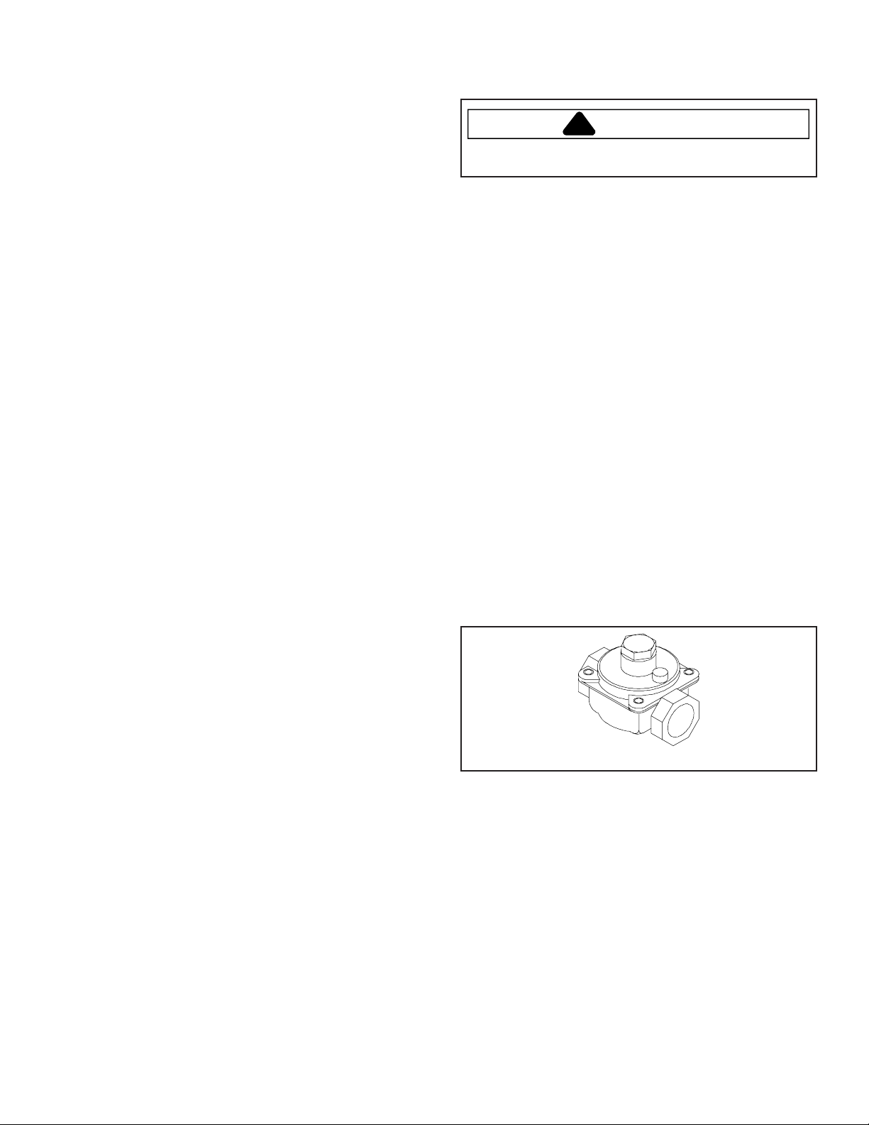
Regulator may have 2 inlets. Remove plug from bottom
inlet of pressure regulator to create 90° connection.
Remove plug from side inlet of pressure regulator to
create a straight connection. Locate pressure regulator
according to gas supply location.
• Support regulator when installing gas supply.
• Do not overtighten fitting or hard pipe when attaching to
gas regulator. Overtightening may crack regulator.
Precautions
• Do not cook food directly on cooktop surface, always
use cookware on side burner(s).
• Do not mix household cleaning products. Chemical
mixtures may interact with objectionable or even
hazardous results.
• Do not put plastic items on warm cooking areas.
They may melt and stick.
• Do not leave fat heating unless you remain nearby. Fat
can ignite if overheated by spilling onto hot surfaces.
• Do not allow pots to boil dry as this can cause damage
to cooking surface and pan.
• Do not use grill for storage or as a display counter.
© 2005 Maytag Services 16025981 5
Gas Supply Location
Locate gas supply so manual shut-off valve is accessible
after installation. Gas supply can be installed in adjacent
cabinet or behind access panel. Avoid interference with
electrical connection.
Regulator
Page 6
Safety Information
Gas Connection
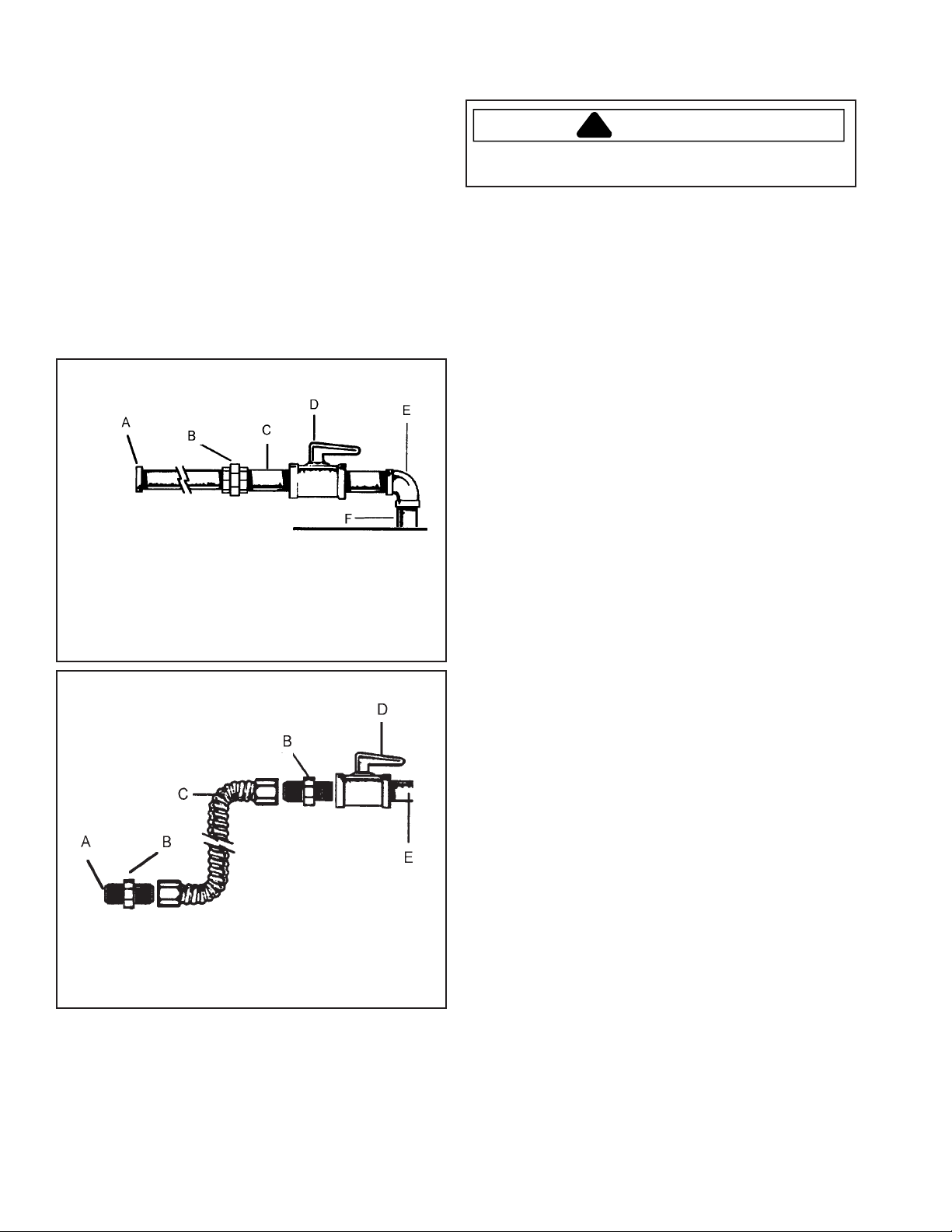
Connect gas supply to regulator using hard pipe or a
flexible connector. Pressure regulator supplied with this
appliance has a ½-inch NPT female connection.
• A manual shut-off, not supplied with grill, must be
installed in an accessible location outside of grill.
• Use joint compound that is resistant to action of
propane gas on all male pipe threads.
• Use supplied pressure regulator only.
• Do not overtighten gas fitting when attaching to
pressure regulator. Overtightening may crack regulator.
• Support pressure regulator with wrench when installing
gas fitting.
Hard Piping
Testing for Gas Leaks
WARNING
!
To avoid property damage or serious personal injury,
never use a lighted match to test for gas leaks.
After final gas connection is made, test all connections in
gas supply piping and grill for gas leaks.
1. Place soap suds on connection.
• Bubbles appear if leak is present.
2. Tighten joint if leak is at factory fitting.
• If leak is not at factory fitting, unscrew, apply more
joint compound, and tighten to correct leak.
3. Retest connection for leak after tightening.
• Retest any connections that were disturbed.
A— To regulator
B—Union
C—Nipple
D—Manual shut-off valve
E—¾-inch to ½-inch reducing elbow
F—¾-inch service pipe stub
Flexible Connector
A—To regulator
B—Adaptor
C—Flexible connector
D—Manual shut-off
E—¾-inch service pipe stub
6 16025981 © 2005 Maytag Services
Page 7

Safety Information
Product Safety Devices
Safety devices and features have been engineered into the product to protect consumer and servicer. Safety devices
must never be removed, bypassed, or altered in such a manner as to defeat the purpose for which they were intended.
Listed below are various safety devices together with the reason each device is incorporated in the gas ranges.
Pressure Regulator Maintains proper and steady gas pressure for operation of oven controls. Regulator
must be set for the type of gas being used Natural or LP. After servicing regulator,
make certain it is set properly before completing service.
Gas Burner Orifices Universal orifices are used on most valves. They must be adjusted or set for the type
of gas being used Natural
After servicing a valve or orifice verify it is adjusted properly before completing service.
or LP.
© 2005 Maytag Services 16025981 7
Page 8
General Information
General Information
This manual provides basic instructions and suggestions for handling, installing and servicing gas grills.
The directions, information, and warnings in this manual are developed from experience with, and careful testing of
the product. If the unit is installed according to the Installation Instructions, it will operate properly and will require
minimal servicing. A unit in proper operating order ensures the consumer all the benefits provided by clean, modern
gas cooking.
This manual contains information needed by authorized service technicians to install and service gas grills. There
may be however, some parts which need further explanation. Refer to individual technical sheets or the toll-free
technical support line to answer questions from authorized service technicians.
Ordering Replacement Parts
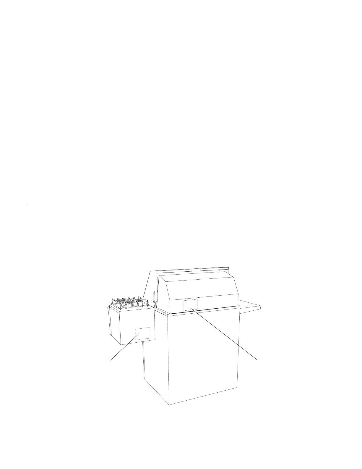
Model numbers are recorded on the rating label. Rating label is located on the rear of the hood area. Before
ordering parts, write down the correct model and serial number from the rating label. This avoids incorrect
shipments and delays. Please refer to parts reference material when ordering replacement parts.
_
__________________ ____________________ ___________________
Model Number Type of Gas Serial Number
___________________
Purchase Date Purchased From Telephone Number
___________________
Installation Date Installed By Telephone Number
NAMEPLATE LOCATION
LOOK UP FROM UNDERNEATH
INTO THE INSIDE OF T HE
BURNER UNIT
____________________ ___________________
____________________ ___________________
NAMEPLATE LOCATION
ATTACHED TO THE
OUTSIDE ON THE FIXED
HOOD OF THE UNIT
8 16025981 ©2005 Maytag Services
Page 9

General Information
Model Identification
Complete registration card and promptly return. If
registration card is missing:
• For product information call 1-866-820-9401 or visit
the Web Site at www.jadeappliances.com
When contacting provide product information located on
rating plate. Record the following:
Model Number: ___________________
Manufacturing Number: ___________________
Serial or S/N Number: ___________________
Date of purchase: ___________________
Dealer’s name and address: ___________________
Service
Keep a copy of sales receipt for future reference or in
case warranty service is required. To locate an
authorized servicer:
• For Jade product call 1-866-820-9401 or visit the Web
Site at www.jadeappliances.com
Warranty service must be performed by an authorized
servicer. We also recommend contacting an authorized
servicer, if service is required after warranty expires.
Receiving Grill
Inspect grill thoroughly at the time of delivery.
Immediately report any visible damage to carrier.
Damage not discovered until after accepting delivery
can still be claimed by using a concealed damage report
form, available from the carrier’s agent.
All shipments, i.e., complete grill or parts, are shipped at
the buyer’s risk. Jade’s responsibility ends when the
consignment is accepted by the carrier in “good order”.
Jade supports damage claims by supplying invoices,
bills, and other documentation as needed. Providing this
assistance however, does not imply any responsibility for
settling claims. Do not deduct claims for loss or damage
from the invoice and do not withhold payment pending
adjustment of claims. Do not return any units or parts for
credit written consent.
Unpacking Grill
• Uncrate grill from packaging material.
• Remove all packing and printed material packed with
grill.
• Remove burner grates, burner caps, grill, vent cover,
and pressure regulator from packing material.
Parts and Accessories
Purchase replacement parts and accessories over the
phone. To order accessories for your product call:
• For Jade product call 1-866-820-9401 or visit the Web
Site at www.jadeappliances.com
Functional Operation
Burners
Spark ignitors are used on each burner. The ignitor is
located at each gas inlet to provide a grounding surface
for ignition.
Spark System
The spark ignition system consists of a solid state
module and spark ignitors.
Turning a ignitor knob or pressing the spark ignition
button sends approximately 2 sparks per second to the
spark ignitors. This causes a demand for spark from the
spark module containing an electronic circuit which
produces 12 VDC voltage pulses.
©2005 Maytag Services 16025981 9
Page 10
Troubleshooting Procedures
!
To avoid risk of electrical shock, personal injury or death; disconnect power to oven before servicing, unless
testing requires it.
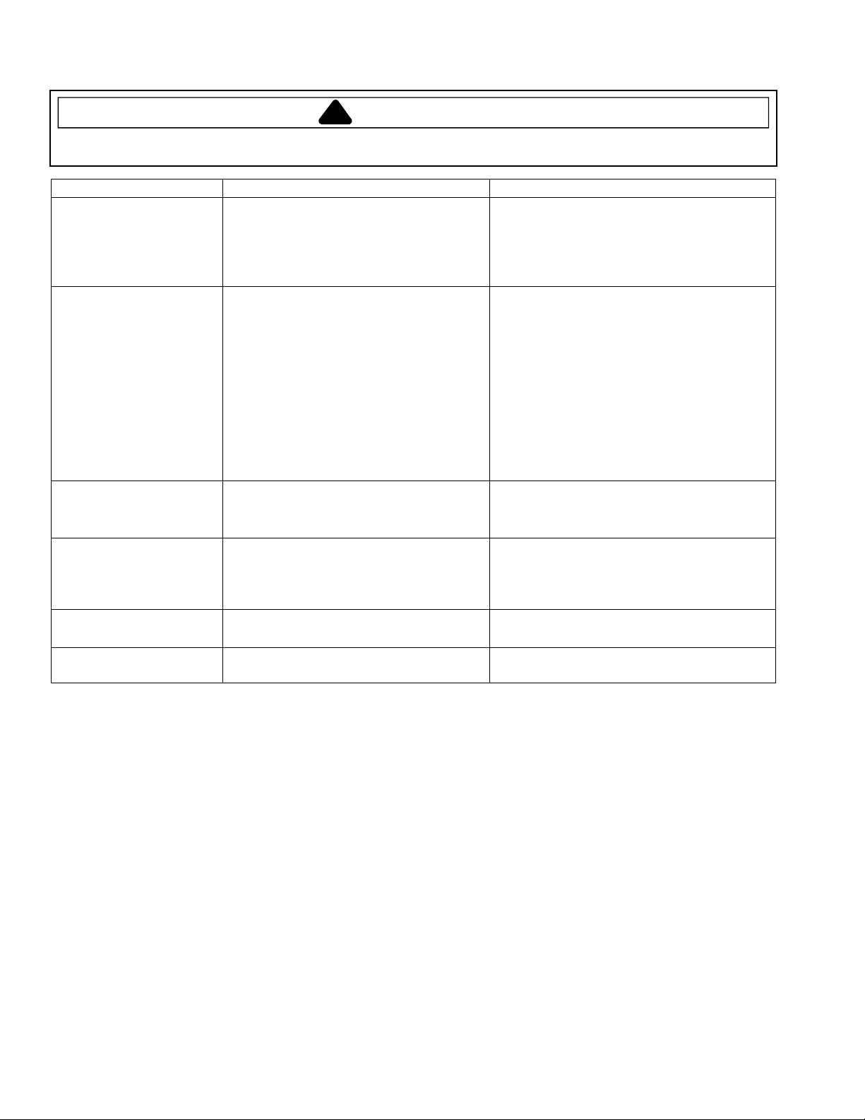
Problem Possible Cause Correction
Poor ground at ignitor ...............................
Burners will not ignite;
no spark at burner.
No spark or only random
spark at one ignitor.
Flame blows away from
burner.
Sooting from burner
flame.
Floating flame.
Gas smell.
Weak or failed spark module ....................
Low gas pressure......................................
Check for cracked ignitor or pinched
ignitor wire ................................................
Poor continuity to ignitor ...........................
Bad ground connection or lack of
continuity to ground or ignitor ...................
Cracked or broken ignitor extension
lead ...........................................................
Too much air .............................................
Gas pressure too high...............................
Draft around grill area ...............................
Too little primary air ..................................
If using LP gas, grill may not be
properly converted. ...................................
Blocked burner ..........................................
Not enough air ..........................................
Leak in pipe joints.
WARNING
• Verify spark.
• Replace spark module
battery 9 VDC.
• Verify pressure 4” WCP for natural, 10”
WCP for LP.
• Replace ignitor lead or electrode.
• Verify spark adjustment.
• Tighten ground connection and correct
any breaks in ground path from ignitor
path to unit ground path.
• Replace ignitor lead.
• Slightly close air shutter to burner.
• Verify correct gas pressure
• Eliminate source of draft.
• Open air shutter on burner.
• Verify correct conversion procedures.
Some yellow tipping is normal on LP.
• Check for possible blockage to burner.
• Open air shutter.
• Verify gas connections and tighten if
necessary.
10
16025981 © 2005 Maytag Services
Page 11
Component Testing Procedures
!
WARNING
To avoid risk of electrical shock, personal injury or death; disconnect power and shut off gas to unit before
servicing, unless testing requires power.
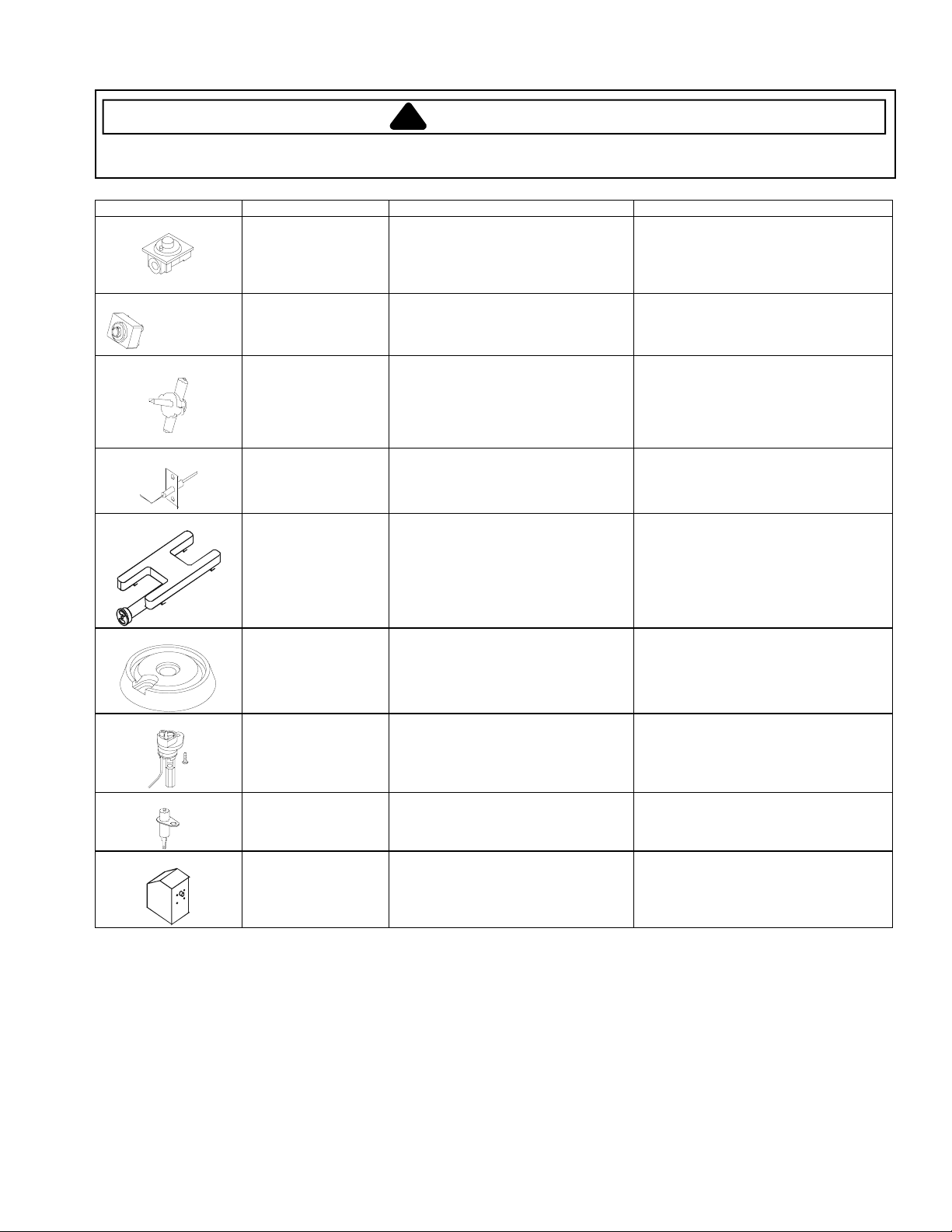
Illustration Component Test Procedure Results
Pressure regulator Verify gas pressure Water Column
Spark module Test for voltage at terminals
Valve
Ignitor Test for resistance of spark lead ..........
H – Burner Verify gas is supplied...........................
Pressure (WCP).
If on LP service, verify proper gas
supply conversion.
L and N...........................................
Polarity and ground ........................
Verify gas is supplied.
Orifice adjusted for
Natural or LP.
Adjust set screw for simmer control.
Test ignitor to chassis ..........................
4
" (WCP) Natural
"(WCP) LP/Propane
10
12 VDC
Not subject to polarity
See conversion section.
Continuity
No continuity from ignitor to chassis.
Check for obstructions in burner ports.
Top surface burner
Holder orifice Verify gas pressure (WCP).
Spark ignition
electrode
Rotisserie Motor Test for voltage at terminals
Verify gas is supplied...........................
Verify burner cap is positioned
correctly.
Check orifice for debris.
Test for resistance of spark lead ..........
Test ignitor to chassis ..........................
Check for obstructions in burner ports.
4
" (WCP) Natural
" (WCP) LP/Propane
10
Clean as needed.
Continuity
No continuity from ignitor to chassis.
120 VAC
© 2005 Maytag Services 16025981 11
Page 12
Disassembly Procedures
WARNING
!
To avoid the risk of electrical shock, personal injury or
death; shut off gas supply before following any
disassembly procedure.
Removing and Replacing Built-In Unit
1. Turn off gas supply to the grill.
NOTE: To avoid property or unit damage, place a
protective covering down to set unit on.
2. Disconnect or unplug any power supply unit by
junction box or outlet depending on connection.
3. Disconnect off gas supply from main gas supply line.
4. Reinstall grill, using Installation Instructions.
Hood Thermometer
Remove thermometer from the hood, by pushing the
stem of the thermometer from the inside of the hood.
Hood Handle
1. Remove screws securing handle bracket to front
hood.
NOTE: Once handle bracket is removed hood handle is
no longer secured.
2. Remove hood handle from handle bracket still
secured to front hood.
3. Replace failed component and reverse procedures to
reassemble.
Front Hood / Spit Saddle Brackets
1. Turn off gas supply to the grill.
2. Open hood to gain access to hinge points.
3. Remove nuts from bolts securing hinge points on spit
saddle brackets.
4. Remove spit saddle brackets from bolts each side.
5. Lower hood to closed position.
6. Remove bolts and spacers (each side) securing front
hood to rear hood.
7. Slowly raise front hood upward to remove from rear
hood.
8. Replace failed component and reverse procedures to
reassemble.
Rear Hood
Knob Bezel(s)
1. Turn off gas supply to the grill.
2. Remove burner knobs from control panel, by pulling
knobs straight off.
• Wrap screwdriver with tape or rag to prevent
scratching knobs, if using to assist in removal.
3. Remove screws securing knob bezel to control
panel.
4. Replace failed component and reverse procedures to
reassemble.
Front Panel
1. Turn off gas and power supply to the cooktop.
2. Remove burner knobs from control panel, by pulling
knobs straight off.
3. Remove smoker tray, if equipped.
4. Remove screws securing control panel to unit
chassis (one on each end).
5. Pull bottom portion of control panel outward and slide
downward to remove completely from unit.
6. Replace failed component and reverse procedures to
reassemble.
Burner Valve(s)
1. Turn off gas supply to the grill.
2. Remove front panel, see "Front Panel" procedure.
3. Disconnect all gas lines from burner valves.
4. Remove top bolts and nuts securing manifold pipe.
5. Loosen bottom bolts and nuts securing manifold
pipe.
6. Rotate top portion of the manifold pipe forward to
allow access for valve removal.
7. Remove burner valve from manifold pipe, by
unscrewing burner valve from manifold pipe.
8. Replace failed component and reverse procedures to
reassemble.
NOTE: When installing, use pipe dope compound.
Perform gas leak test to ensure unit will not leak
and grill operates properly.
NOTE: Units prior to 2003, rear hood was welded to
heating chamber.
1. Turn off gas supply to the grill.
2. Remove front hood, see Front Hood procedures.
3. Remove cooking grates from unit, by raising grates
out of burner box area.
4. Remove infra-red broiler bracket, see Infarred Broiler
Bracket procedures.
5. Remove screws securing front portion of rear hood.
6. Remove rear hood from unit.
7. Replace failed component and reverse procedures to
reassemble.
12 16025981 ©2005 Maytag Services
Gas Line(s)
1. Turn off gas supply to the grill.
2. Remove front panel, see "Front Panel" procedure.
3. Disconnect gas line from burner valve outlet and
burner inlet.
NOTE: If replacing infra-red burner gas line, see
"Infra-red Burner' procedure, for gas line
disconnection.
4. Replace failed component and reverse procedure to
reassemble.
NOTE: When installing, perform gas leak test to ensure
unit will not leak and grill operates properly.
Page 13
Disassembly Procedures
WARNING
!
To avoid the risk of electrical shock, personal injury or
death; shut off gas supply before following any
disassembly procedure.
Ignitor(s)
1. Turn off gas supply to the grill.
2. Remove cooking grates and briquet grates from
heating chamber.
3. Remove front panel, see "Front Panel" procedure.
4. Disconnect wire terminal from ignitor.
5. Remove bolts and nuts securing ignitor bracket to
heating chamber.
6. Remove ignitor bracket and ignitor from unit.
7. Remove bolt and nut securing ignitor to ignitor
bracket.
8. Replace failed component and reverse procedure to
reassemble.
H - Burner
1. Turn off gas supply to the grill.
2. Remove cooking grates and briquet grates from
heating chamber.
3. Raise rear of h - burner to release from bracket and
slide burner to the rear of the heating chamber to
remove.
4. Replace failed component and reverse procedure to
reassemble.
Infra-red Sear Burner
1. Turn off gas supply to the grill.
2. Remove searing grate from heating chamber.
3. Remove front panel, see "Front Panel" procedure.
4. Remove bolt and nut securing ignitor to heating
chamber.
5. Raise rear of infra-red sear burner to release from
bracket and slide burner to the rear of the heating
chamber to remove.
6. Replace failed component and reverse procedure to
reassemble.
Burner Support Bracket
1. Turn off gas supply to the grill.
2. Remove cooking grates and briquet grates from
heating chamber.
3. Raise rear of burner to release from bracket and
slide burner to the rear of the heating chamber to
remove. (Remove all burners from heating
chamber).
4. Remove screws securing support bracket to heating
chamber.
5. Remove support bracket from heating chamber.
6. Replace failed component and reverse procedure to
reassemble.
Spark Ignitor
NOTE: First determine the spark ignitor that needs
replaced.
1. Turn off gas supply to the grill.
2. Remove grease tray, by pulling tray out of unit (if
equipped).
3. Remove nut securing spark ignitor to bull nose.
4. Gently pry spark ignitor secured by stud and lower
spark ignitor from bull nose.
5. Label and disconnect wire terminals from spark
ignitor.
6. Replace failed component and reverse procedure to
reassemble.
Infra-red Broiler Ignitor
1. Turn off gas supply to the grill.
2. Remove screw securing ignitor bracket to infra-red
broiler bracket.
3. If screws contain nuts, remove access panel located
on the back of the rear hood to gain access to nuts.
4. Remove ignitor and bracket to gain access to wiring.
5. Disconnect wire terminal from ignitor to allow
complete removal from unit.
6. Remove screw and nut securing ignitor to bracket.
7. Replace failed component and reverse procedures to
reassemble.
Infra-red Broiler
NOTE: It may be necessary to remove infra-red broiler
ignitor to avoid damaging, before removing
infra-red broiler.
1. Turn off gas supply to the grill.
2. Remove screw securing access panel to the back of
the rear hood.
3. Remove access panel from rear hood.
4. Disconnect gas line from brass flange.
5. Remove screws securing infra-red broiler, one
located on each end.
6. Lift infra-red broiler out of infra-red broiler bracket.
7. Replace failed component and reverse procedures to
reassemble.
©2005 Maytag Services 16025981 13
Page 14
Disassembly Procedures
WARNING
!
To avoid the risk of electrical shock, personal injury or
death; shut off gas supply before following any
disassembly procedure.
Infra-red Broiler Bracket
1. Turn off gas supply to the grill.
2. Remove infarred broiler ignitor, see "Infra-red Broiler
Ignitor" procedure.
3. Remove infarred broiler, see "Infra-red Broiler"
procedure.
4. Remove cooking grates from unit, by raising grates
out of burner box area.
5. Remove screws securing bottom portion of broiler
bracket and support bar to the inside of rear hood.
6. Remove screws securing top portion of broiler
bracket on the back of the rear hood.
7. Slide one end of the broiler bracket forward to
remove from burner box area.
8. Replace failed component and reverse procedures to
reassemble.
Gas Regulator
1. Turn off gas supply to the grill.
2. Gas supply line to gas regulator.
• Hard piping - disconnect gas supply line at the
union.
• LP Tank - disconnect gas supply line from tank.
3. Disconnect appropriate piping from gas regulator.
4. Unscrew gas regulator from remaining piping.
5. Replace failed component and reverse procedure to
reassemble.
NOTE: When installing, use pipe dope compound.
Perform gas leak test to ensure unit will not leak
and grill operates properly.
Side Burner
1. Turn off gas supply to the grill.
2. Remove grate, burner cap, and burner ring from side
burner.
3. Disconnect gas line from the side burner.
4. Disconnect wire terminal from ignitor.
5. Remove screws securing side burner hub to chassis.
6. Replace failed component and reverse procedure to
reassemble.
Base Unit
Door / Door Hinge
1. Open door to gain access to hinges.
2. Push on metal tab to release door from hinge insert.
3. Remove screws securing hinge insert from cabinet
and door.
4. Reverse procedure to reassemble.
Drawer
1. Pull drawer out to the stop position.
2. Release locking tabs on each side of the drawer
slider.
3. Pull drawer out to completely release drawer from
slider.
4. Reverse procedure to reassemble.
Drawer Slider
1. Remove drawer, see "Drawer" procedure.
2. Remove screws securing slider to the cabinet.
3. Reverse procedure to reassemble.
Manifold Pipe
1. Turn off gas supply to the grill.
2. Remove front panel, see "Front Panel" procedure.
3. Disconnect all gas lines from burner valves.
4. Remove top and bottom bolts and nuts securing
manifold pipe to unit chassis.
5. Remove surface valves from manifold pipe.
6. Replace failed component and reverse procedure to
reassemble.
NOTE: When installing, use pipe dope compound.
Perform gas leak test to ensure unit will not leak
and grill operates properly.
14 16025981 ©2005 Maytag Services
Casters
1. Place a block underneath the unit to allow access to
the caster bolts.
2. Remove bolts securing caster to the bottom of the
base unit.
3. Reverse procedure to reassemble.
Page 15
Disassembly Procedures
WARNING
!
To avoid the risk of electrical shock, personal injury or
death; shut off gas supply before following any
disassembly procedure.
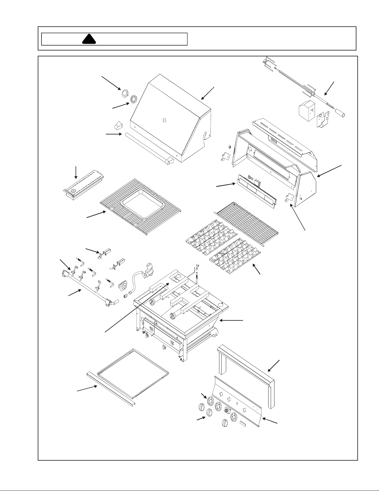
Thermometer
Bezel
Hood
Handle
Smoker
Box
Cooking Grates
Ignitors
Front Hood
Infra-red
Broiler
Rotisserie
Assembly
Rear Hood
Assembly
Spit
Saddle
Brackets
Valv es
Manifold
DripPan
H- Burner
Bezel
Knob
Briquetts
Heating
Chamber
Bullnose
Assembly
Front Panel
Typical Grill Component Layout
©2005 Maytag Services 16025981 15
Page 16
Disassembly Procedures
WARNING
!
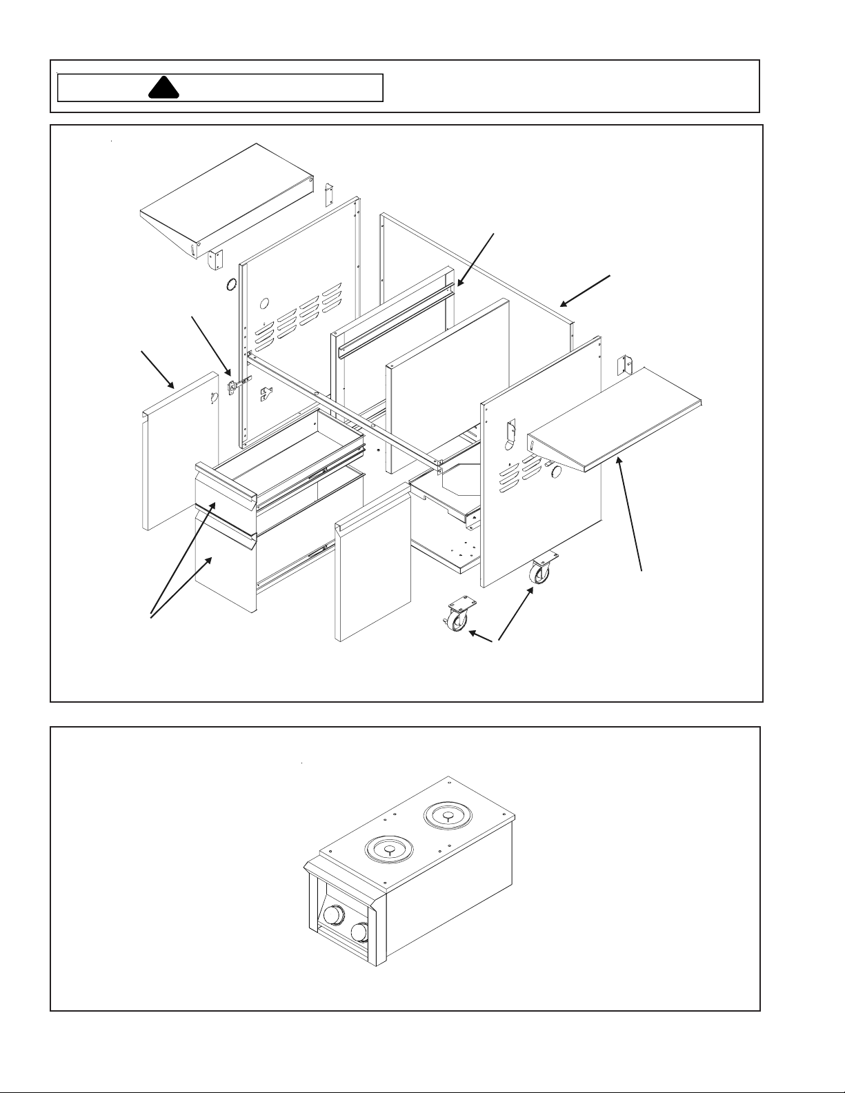
Hinge
Door
To avoid the risk of electrical shock, personal injury or
death; shut off gas supply before following any
disassembly procedure.
Drawer
Slide
Base
Drawers
Side
Shelf
Casters
Typical Base Unit
Side
Burners
Typical Side Burners
16 16025981 ©2005 Maytag Services
Page 17

Appendix A
A-1 16025981 © 2005 Maytag Services
Page 18
Instruction Sheet
Description: L.P. Conversion for Outdoor Grill Series
FOR YOUR SAFETY
If you smell gas:
1. Shut off gas to the appliance
2. Extinguish any open flame
3. Open lid
4. If odor continues, immediately call
your gas supplier or your fire department
FOR YOUR SAFETY
1. Do not store or use gasoline or other
flammable vapors and liquids in the
vicinity of this or any other appliance
2. An LP cylinder not connected for use
shall not be stored in the vicinity of this
or any other appliance
This conversion kit shall be installed by a qualified service agency in accordance with the
manufacturer’s instructions and all applicable codes and requirements of the authority having
jurisdiction. The information in these instructions must be followed to minimize the risk of fire or
explosion or to prevent property damage, personal injury or death. The qualified service agency is
responsible for the proper installation of this kit. The installation is not proper and complete until
the operation of the converted appliance is checked as specified in these instructions.
If the information in these instructions is not followed exactly, a fire or explosion, may result
causing property damage, personal injury or death
Procedure on other side
© 2005 Maytag Services 16025981 A-2
Page 19
Procedure:
When converting outdoor grill gas valve to L.P. gas, be sure the incoming gas supply line is equipped with a
pressure regulator (located ahead of the unit) that will maintain the gas supply to the grill.
Surface Orifice Conversion:
NOTE: All orifices with no exception must be converted.
NOTE: Care must be taken to avoid damaging the threads on the orifice and/or valve
NOTE: Follow proper orifice quantities and sizes indicated on orifice chart below.
1. Turn equipment shut-off valve handle to the closed position (if so equipped).
2. Remove control knobs from unit, by pulling knobs off the valve stems.
3. Remove four screws securing front panel to chassis, two on each side.
4. Roll top portion of control panel downward to gain access to gas valves.
5. Remove stainless steel grates, briquette trays and main burners from firebox surface.
6. Replace Natural orifice(s) with Propane orifice(s) from main front gas valve by carefully screwing onto the gas
valve.
7. The infrared orifice is located at the rear of the grill.
8. Remove rear vent cover to access infrared orifice.
9. Disconnect flex line from elbow.
10. Replace infrared Natural orifice with Propane orifice by carefully screwing onto elbow.
11. The smoker orifice can be removed by pulling elbow assembly off the burner tube, then removing the orifice at
the elbow. Install new orifice into elbow assembly.
NOTE: The Natural gas regulator is convertible to Natural or Propane gas by flipping gas cap, when unit is being
hard piped to permanent gas supply.
12. Remove Natural gas regulator from gas manifold (if required)
13. Install propane regulator with hose to gas manifold (if required)
20. Verify that all the internal surfaces and components of the gas valve and new orifice are clean
21. Before turning on gas supply, check for leaks with a soap and water solution -
DO NOT USE AN OPEN FLAME - and verify that all gas valves are turned to the “OFF” position.
22. Adjust air shutters for optimum burner performance.
23. Complete conversion label and attach to BBQ next to rating plate
Orifice Chart
Item Btuh Natural
Main
Burner
Smoker
Burner
Small IR
Burner
Large IR
Burner
Sear
Burner
Side
Burner
Inner
Side
Burner
Outer
25,000 #42 #53 2 n/a 2 3 2 2 3
2,700 #65 #74 n/a 1 1 1 1 1 1
14,000 #50 #57 n/a 1 1 n/a n/a n/a n/a
16,000 #48 #56 n/a n/a n/a 1 1 1 1
20,000 #45 #55 n/a 2 n/a n/a 1 1 n/a
17,500
total
17,500
total
Orifice
#67 #76 n/a n/a n/a n/a n/a 2 2
#50 #61 n/a n/a n/a n/a n/a 2 2
Propane
Orifice
DBQ30MA DBQ30IA DBQ30PA
JBQ30BA
DBQ42PA
JBQ42BA
DBQ42SA DBQ55TA JBQ55HA
A-3 16025981 © 2005 Maytag Services
Page 20

Appendix B
©2005 Maytag Services 16025981 B–1
Page 21
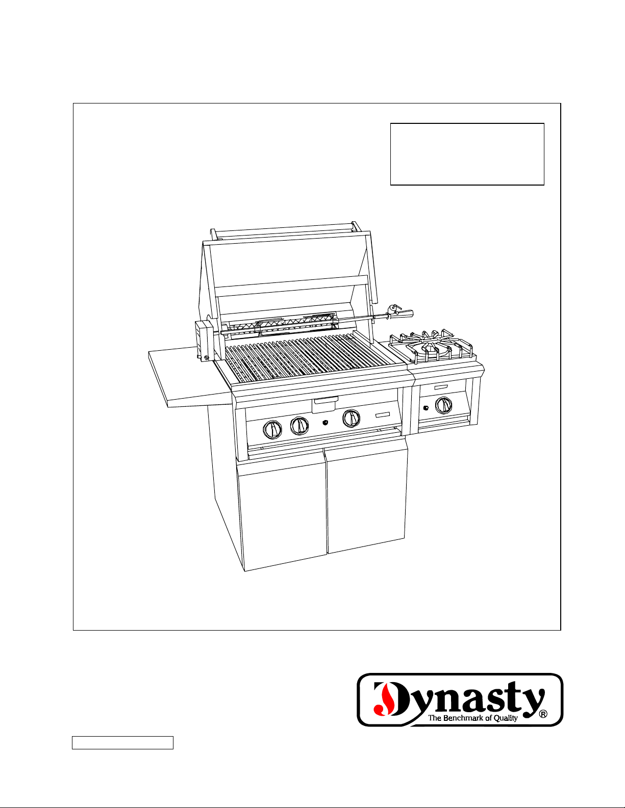
INSTALLATION AND USER MANUAL
MODELS:
DBQ-30 DBQ-30F
DBQ-42 DBQ-42F
DBQ-54 DFB
DSB-1
DSB-2
DYNASTY OUTDOOR GAS GRILL
P/N 2420100000 08/03
B–2 16025981 ©2005 Maytag Services
Page 22

Congratulations!
When you purchased your Dynasty Outdoor Gas Grill you
purchased a grill that was created with you in mind.
y
Congratulations!
When you purchased your Dynasty Outdoor Gas Grill you
purchased a grill that was created with you in mind.
Dynasty’s standard features including all welded #304 stainless steel
construction, exclusive 25,000 BTU Dynachrome
TM
burners, long lasting
#304 stainless steel grates and heavy duty spits with extra large meat
holders promise you years of outstanding performance. And, Dynasty’s
many options offer you the opportunity to virtually customize your grill.
Enjoy! And, welcome to our Dynasty family.
This manual is intended to serve as a guide for the operation and maintenance of your new Dynasty
Grill.
Please read it carefully, and keep it handy for reference.
y Installation and service must be performed by a qualified installer, service agency, or the
gas supplier.
y To the installer: Please leave these instructions with the consumer.
To the consumer: Retain these instructions for future reference.
©2005 Maytag Services 16025981 B–3
Page 23
safety
General Safety Requirements
1. Installation of this appliance must conform with
local codes or, in the absence of local codes, with
either the National Fuel Gas Code, ANSI Z223.1,
or CAN/CGA-B149.1, Natural Gas Installation
Code or CAN/CGA-B149.2, Propane Installation
Code.
2. The utilization of an external electrical source
requires that when installed, this gas appliance be
electrically grounded in accordance with local
codes or, in the absence of local codes, with the
National Electrical Code, ANSI/NFPA 70, or the
Canadian Electrical Code, CSA C22.1.
3. This outdoor gas cooking appliance and its
individual shutoff valve must be disconnected from
the gas supply piping system during any pressure
testing of that system at test pressures in excess of
½ psi (3.5 kPa).
4. This outdoor gas cooking appliance must be
isolated from the gas supply piping system by
closing its individual manual shutoff valve during
any pressure testing of the gas supply piping
system at test pressures equal to or less than ½ psi
(3.5 kPa).
5. The utilization of a self-contained LP-gas supply
system requires that this self-contained supply
cylinder be constructed and marked in accordance
with the specifications for LP-gas cylinders of the
WARNINGS AND NOTICES
U.S. Department of Transportation (DOT) or the
National Standards of Canada, CAN/CSA-B339,
Cylinders, Spheres and Tubes for the
Transportation of Dangerous Goods.
6. California Proposition 65
– WARNING
The burning of gas cooking fuel generates some
byproducts that are on the list of substances, which
are known by the State of California to cause cancer
or reproductive harm. California law requires
businesses to warn customers of potential exposure
to such substances. To minimize exposure to these
substances, always operate this unit according to the
use and care manual, ensuring you provide good
ventilation when cooking with gas.
WARNING: If the information in this
manual is not followed exactly, a fire
or explosion may result causing
property damage, personal injury or
NOTICE: All gas installations,
conversions, and/or adjustments must
be performed by an authorized service
agent.
B–4 16025981 ©2005 Maytag Services
Page 24
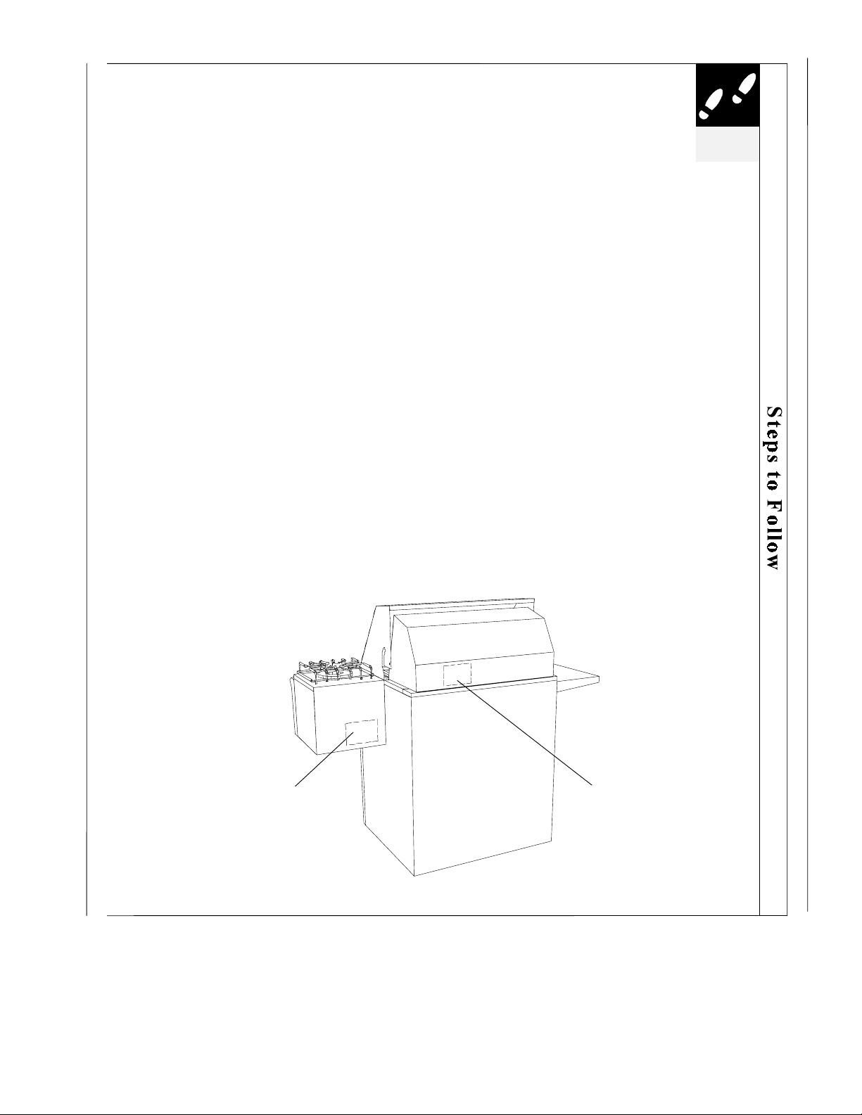
Locate the model and serial numbers.
Your new grill model and serial numbers are included on a nameplate located on the
outside hood wall of the grill (see illustration below).
Open Burner, model and serial numbers are included on a nameplate located on the
inside wall of the open burner unit. Visually access the nameplate label from the front
and bottom of the burner looking up into the inside of the unit. Use a flashlight if
lighting conditions require it (see illustration below).
Complete and return the warranty card.
Please take a moment to fill out and mail the Warranty Card included with your
Dynasty Grill. Make sure you enter the model and serial numbers of your new appliance
on the Warranty Card.
For future reference, record the following information and refer to it when contacting
the factory or an authorized service agent.
CONSUMER INFORMATION
_
__________________ ____________________ ___________________
Model Number Type of Gas Serial Number
___________________
____________________ ___________________
Purchase Date Purchased From Telephone Number
___________________
____________________ ___________________
Installation Date Installed By Telephone Number
steps to
follow
NAMEPLATE LOCATION
ATTACHED TO THE
OUTSIDE ON THE FIXED
HOOD OF THE UNIT
NAMEPLATE LOCATION
LOOK UP FROM UNDERNEATH
INTO THE INSIDE OF THE
BURNER UNIT
©2005 Maytag Services 16025981 B–5
Page 25

f
r
safety
General Precautions
SAFETY INSTRUCTIONS
Please read before installing and operating your new Dynasty Grill
1) Your Dynasty gas grill should be properly installed
and serviced. Refer to the installation instructions
provided in this manual. Ask the installer where the
gas supply shut-off is located and how to operate it.
All gas lines must have a shut-off that is readily and
easily accessible.
2) Be sure your grill is correctly adjusted by a qualified
service technician or installer for the type of gas
(Natural or LP) on which it is to be used. Your grill
can be converted for either type of gas. Refer to the
installation instructions provided in this manual.
3) If you smell gas, call a qualified service technician.
Do not try to fix the problem yourself. Follow the
instructions entitled “What To Do If You Smell
Gas” on page 1.
4) Caution: To prevent fire or smoke damage, remove
all packing material from the grill before operating
it.
5) Before starting to cook, clean the grill thoroughly
with hot, soapy water. This is necessary to remove
residuals and solvents used at the factory to clean
and remove dirt, oil and grease which may have
remained from the manufacturing process. The
grates should be thoroughly cleaned.
9) Never grill without the drip pan in place and pushed
all the way to the back of the grill. Without it hot
grease could leak downward and produce a fire or
explosion hazard.
10) Keep any electrical supply cord, or the rotisserie
motor cord away from the heated areas of the grill.
11) Never use the grill in windy conditions. If located in
a consistently windy area (oceanfront, mountaintop,
etc.) a windbreak will be required. Always adhere to
the specified clearances listed in page 6.
12) The area surrounding your Dynasty grill should be
kept clean, and free from flammable liquids and
other combustible materials such as mops, rags,
brooms, etc., as well as solvents, cleaning fluids, and
gasoline.
13) Do not use the grill or open burners as a storage area
for flammable or plastic items, which may ignite.
Do not store spare LP cylinders or flammable
materials in the cart or under a built-in location.
An LP cylinder not connected for use should not
be stored in the vicinity of this or any other
appliance.
14) Never line surface burners with tin foil.
6) Spiders and other insects can nest in the burners of
the grill and block the gas and airflow to the burner
ports. This creates a dangerous condition that can
result in a fire from behind the valve panel. Inspect
and clean the burners periodically; follow guidelines
in Cleaning and Maintenance on pages 34-35.
7) In the event a burner goes out and gas escapes, turn
off burner knobs, open fully the grill hood and let
the air out. Do not attempt to use the appliance until
the gas has had time to dissipate.
8) Unless specifically recommended in this manual, do
not repair or replace any part of the grill. A
qualified technician should perform all other
service. Warranty service must be performed by an
authorized service agency.
15) When the unit is not in use and connected to a selfcontained LP-gas supply system, the gas must be
turned off at the supply cylinder.
16) When not in use it is permissible for a self-contained
LP-gas outdoor appliance, to be stored indoors only
if the cylinder is disconnected and removed.
Cylinders must be stored outdoors out of the reach o
children and must not be stored in a building, garage
or any other enclosed area.
17) Never locate this appliance under an overhead,
unprotected combustible construction or enclosed
area such as a garage, shed, or breezeway. Keep clea
of trees and shrubs.
18) This outdoor gas cooking appliance is not intended
to be installed in or on recreational vehicles and/or
boats.
B–6 16025981 ©2005 Maytag Services
Page 26
SAFETY INSTRUCTIONS
(continued)
safety
Precautions Regarding Children
1) Never leave children unattended in the area where
the grill is being used.
2) Do not store items of interest to children around or
below the grill, in the cart or masonry enclosure.
3) Never allow children to sit or stand on any part of
the grill or to crawl inside a cart or enclosure.
Use Precautions
1) Never leave the grill and top burners unattended
while using high flame settings. Boilovers cause
smoking, and greasy boilovers may ignite.
2) Always use the proper size pan. Select utensils
with flat bottoms large enough to cover the burner.
The use of undersized utensils exposes the sides of
the utensils to direct contact with a portion of the
flame. This can scorch utensils, and hamper
cleanup. Excessive flames on large stainless steel
pots can result in permanent discoloration. For
best results, we recommend commercial quality
aluminum pans and utensils.
3) Always position handles of utensils inward, so
they do not extend over adjacent work areas or
cooking areas. This reduces the risk of burns,
ignition of flammable materials, and spillage due
to accidental contact with the utensils.
4) Do not use water on grease fires. Never pick up a
flaming pan. Turn appliance off and smother the
flaming pan with a tight-fitting lid, cookie sheet or
flat tray. For flaming grease outside of the pan,
smother with baking soda, or use a dry chemical or
foam type fire extinguisher.
5) Never let clothing, potholders or other flammable
materials come in contact with or too close to any
grate, burner or hot surface until it has cooled.
Fabric may ignite and result in personal injury.
6) When using the grill, do not touch the grill rack,
burner grate or immediate surroundings as these
areas become extremely hot and could cause burns.
7) Proper apparel is a safety consideration. Never
wear loose fitting or hanging garments while using
your Dynasty grill.
8) Only use dry potholders – do not use a towel or
other bulky cloth in place of potholders. Moist or
damp potholders used on hot surfaces could cause
burns from steam.
9) Do not heat any unopened glass or metal container
of food on the grill. Pressure may build up and
cause the container to burst resulting in serious
harm or damage to the grill.
10) Do not use charcoal in the grill.
SAVE THIS MANUAL
FOR FUTURE
REFERENCE
©2005 Maytag Services 16025981 B–7
Page 27
installation
Safe and satisfactory operation of your Dynasty grill
INSTALLATION OF YOUR DYNASTY GRILL
depends upon its proper installation. The installation,
adjustments and service of your Dynasty grill must be
performed only by qualified installers and service
technicians. This is necessary to insure proper
operation and also to prevent accidents.
Location
When determining a suitable location take into account concerns such as exposure to wind,
proximity to traffic paths and keeping any gas supply lines as short as possible. Locate the grill
only in a well ventilated area. For free standing models allow 12” from the sides and rear to
adjacent combustible construction.
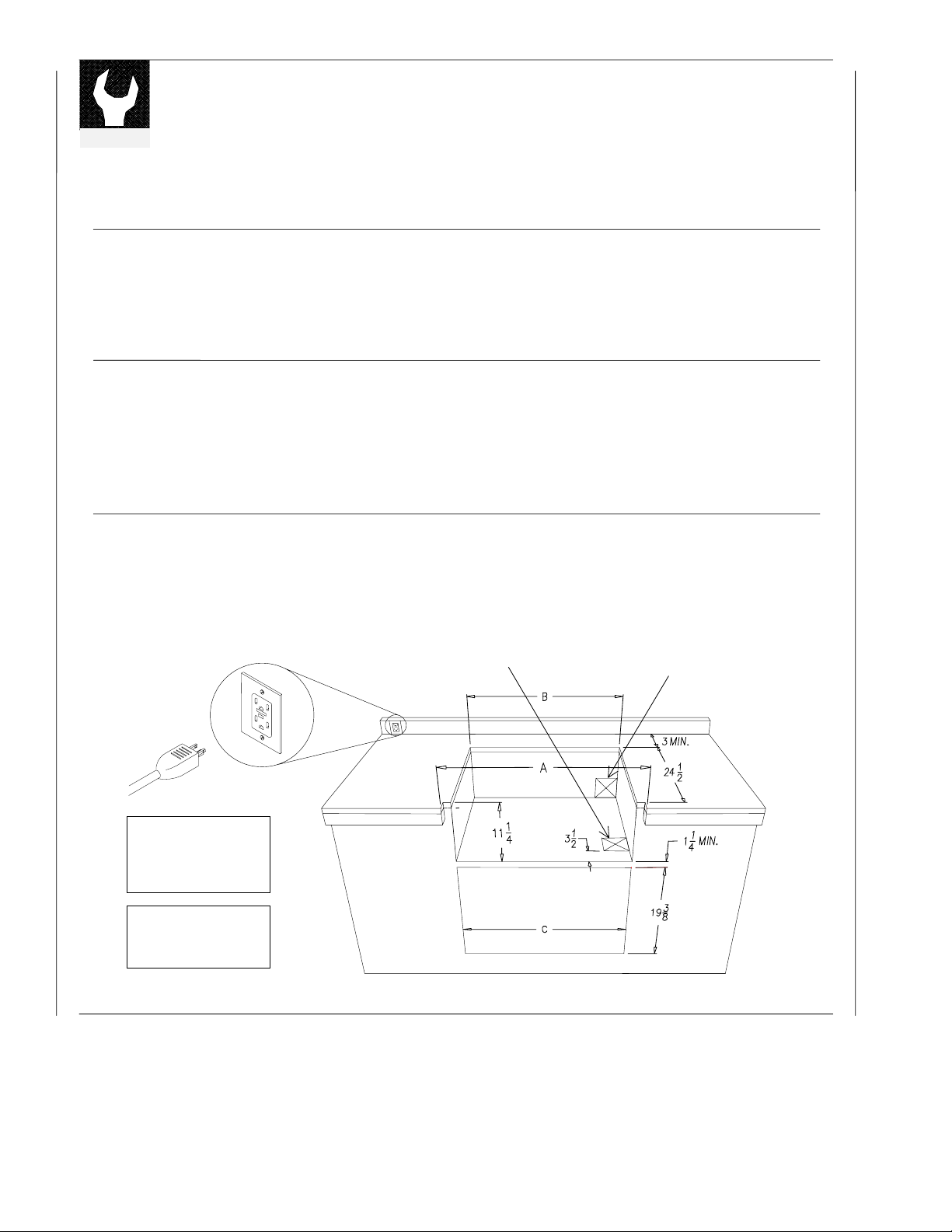
Built-in Installation
Your Dynasty grill is designed for easy installation into a non-combustible enclosure.
The supporting deck and counter must be level and flat. When determining the final location for
your grill it is required that ventilation holes be provided in the enclosure so that gas will not
become entrapped in the event of a leak (See pages 8 and 9).
Built-in Design Models
If using a rear wall, locate the weather proof electrical outlet on the left-hand side for the rotisserie
motor. The rotisserie motor requires a 110/120 volt supply. The power supply cord on the motor is
equipped with a 3 prong (grounded) plug for protection against shock hazard. Do not cut or remove
the grounding prong from the plug.
4 X 4 MIN. OPENING FOR
BOTTOM GAS CONNECTION
4 X 4 MIN. OPENING FOR
REAR GAS CONNECTION
3 PRONG PLUG
A B
DBQ-30 30 1/8 29
DBQ-42 42 1/8 41
DBQ-54 54 1/8 53
DAD-30 28 3/8
DAD-42 40 3/8
DYNASTY BUILT-IN GRILLS
DYNASTY ACCESS DOORS
C
B–8 16025981 ©2005 Maytag Services
Page 28
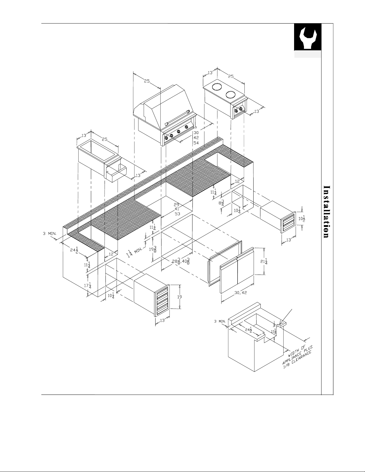
CABINET CUT OUT DIMENSIONS
FOR GAS GRILL AND ACCESSORIES
installation
CUT OUT ON
CABINET
BULLNOSE TYPICAL
FOR GRILL,
SIDEBURNER AND
BARTENDER
DIMENSIONS FOR CABINETS
WITH BULLNOSE
©2005 Maytag Services 16025981 B–9
Page 29
installation
INSTALLATION OF YOUR DYNASTY GRILL
(continued)
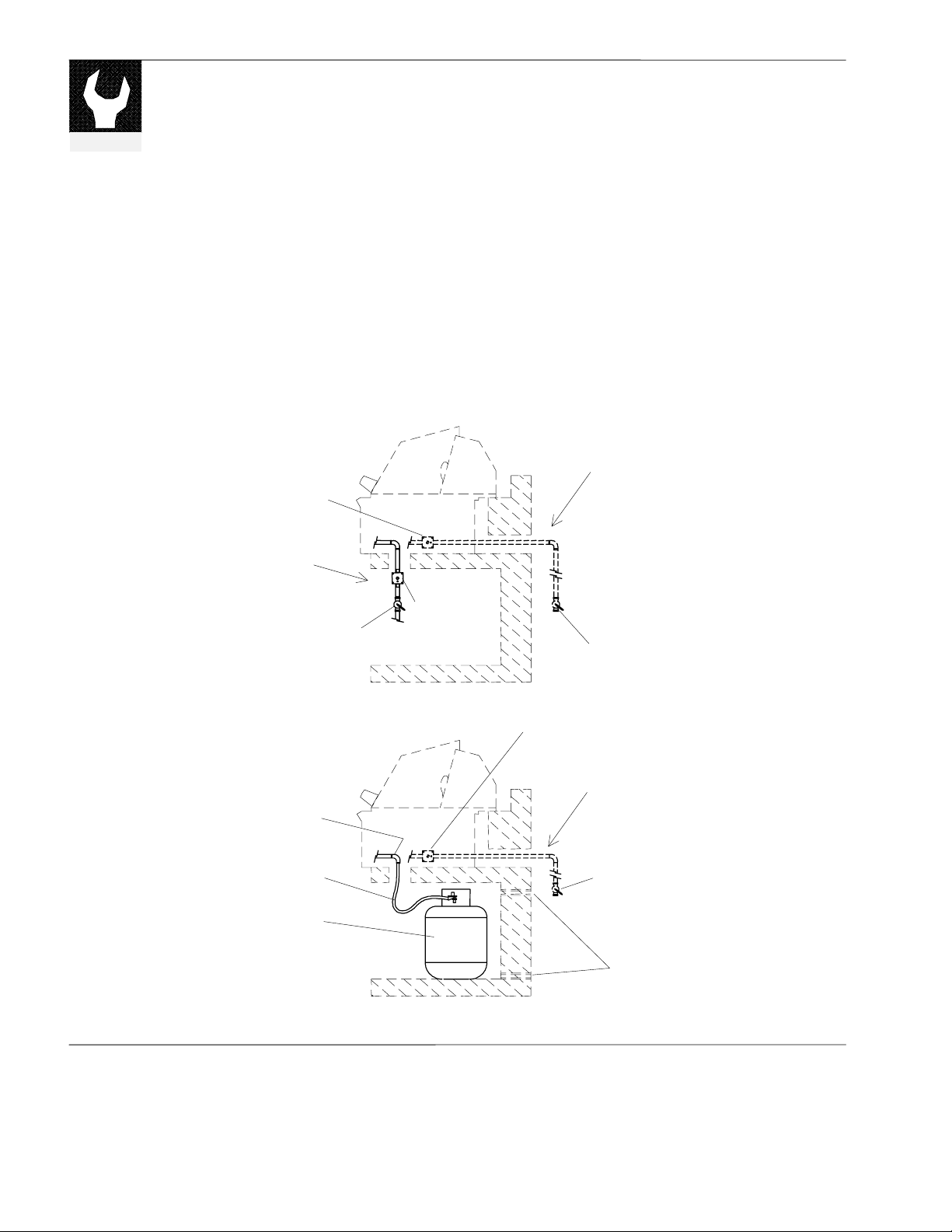
Gas Requirements
Your Dynasty grill is designed to work with either Natural Gas or with LP (Liquid
Propane) Gas. Check your rating plate to make sure the gas supply you are
hooking up to is the gas type the grill is manufactured for (see page 3).
An installer supplied gas shut-off valve must be installed in an easily accessible
location. Only use pipe sealant that is an approved type and is resistant to the
actions of LP gas.
IMPORTANT: Your Dynasty grill is set to work on one of the types of gasses
mentioned above and cannot be used on the other without conversion.
Natural Gas Hook Up
x
(CONVERTIBLE GAS SETTING
BY TURNING CAP OVER)
TYPICAL BOTTOM
GAS CONNECTION
REGULATOR
SHUT-OFF
VALVE
REGULATOR
(CONVERTIBLE
GAS SETTING
BY TURNING
CAP OVER)
TYPICAL REAR
GAS CONNECTION
SHUT-OFF VALVE LOCATED
IN ACCESSIBLE LOCATION
LP Gas Hook Up
x
½ NPT X ½ FLARE
LP REGULATOR AND
HOSE ASSEMBLY
DO NOT PLACE MORE THAN ONE CYLINDER
20 LB (5 GALLON) LP CYLINDER
IN THE ENCLOSURE AT ANY TIME
CYLINDERS THAT ARE NOT CONNECTED
FOR USE SHALL NOT BE STORED WITHIN
THE VICINITY OF THIS OR ANY APPLIANCE
REGULATOR
(CONVERTIBLE GAS SETTING
BY TURNING CAP OVER)
TYPICAL PLUMBED-IN
LP GAS CONNECTION
SHUT-OFF VALVE LOCATED
IN ACCESSIBLE LOCATION
VENTS
(SEE NOTE ON NEXT PAGE)
B–10 16025981 ©2005 Maytag Services
Page 30

NOTE: An enclosure for an LP gas cylinder shall be vented by openings on the level
of the cylinder valve and at floor level. The effectiveness of the opening(s) for
purposes of ventilation shall be determined with the LP-gas supply cylinder in
place. This shall be accompanied by one of the following:
a. One side of the enclosure shall be completely open; or
b. For an enclosure having four sides, a top and a bottom:
1. At least two ventilation openings at cylinder valve level shall be
provided in the sidewall, equally sized, spaced at 180 degrees (3.14
rad), and unobstructed. Each opening shall have a total free area of
not less than ½ square inch per pound (7.1 cm
capacity and not less than a total free area of 10 square inches (64.5
2
).
cm
2. Ventilation opening(s) shall be provided at floor level and shall have a
total free area of not less than ½ square inch per pound (7.1 cm
stored fuel capacity and not less than a total free area of 10 square
inches (64.5 cm
2
). If ventilation openings at floor level are in a
2
/kg) of stored fuel
2
/kg) of
sidewall, there shall be at least two openings. The bottom of the
openings shall be at floor level and the upper edge no more than 5
inches (127 mm) above the floor. The openings shall be equally sized,
spaced at 180 degrees (3.14 rad) and unobstructed.
3. Every opening shall have minimum dimensions so as to permit the
entrance of a 1/8 inch (3.2 mm) diameter rod.
installation
x Gas Manifold Pressure
For natural gas, standard orifices are set for 4” W.C. (Water Column). A natural gas pressure regulator is provided.
For propane (LP) gas, standard orifices are set for 10” W.C. A propane gas regulator with hose attachment for LP
cylinder is provided. For plumbed-in LP installation, use the convertible regulator and set it for LP gas.
x Gas Supply Pressure
Maximum line pressure (before the regulator) for Natural gas and plumbed-in Propane is 14” W.C., ½ psig (3.5 kPa.).
Minimum line pressure for Natural Gas is 7” W.C. Minimum line pressure for propane is 11” W.C.
x Gas Pressure Regulator
The unit must be used with the gas pressure regulator. The regulator will control and maintain a uniform gas pressure
in the manifold. The burner orifices have been sized for the gas pressure delivered by the regulator.
x Cylinder Specification
Any LP gas supply cylinder used with this grill must be approximately 12 inches in diameter and 18 inches high. The
maximum fuel capacity is 20 lbs. of propane or 5 gallons. Full cylinder weight should be approximately 38 lbs. (43.7
lbs. nominal water capacity). Always use the cylinder dust cap on the cylinder valve outlet during transport and when
the cylinder is not connected to the grill.
x Transporting the LP Gas Supply Cylinder
Only one cylinder should be transported at a time. Transport cylinder in an upright and secure manner with control
valve turned off and the dust cap in place.
©2005 Maytag Services 16025981 B–11
Page 31
installation
pp
INSTALLATION OF YOUR DYNASTY GRILL
(continued)
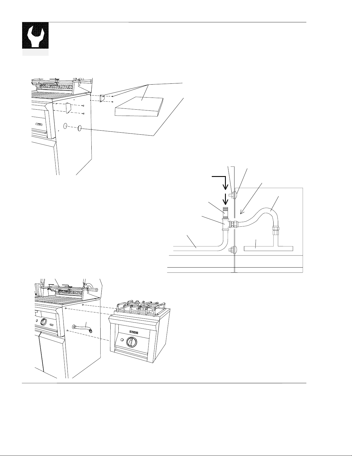
Side Burner Attachment – Model DFB
5) Install the pipe tee assembly to the grill intake
pipe with pipe sealant. Tighten assembly and
align the branch opening of the tee to the hole of
the cabinet.
6) Connect the flexible hose (male end) to the pipe
tee with pipe sealant.
7) Install and secure the DFB Side Burner to the
grill cabinet using 3 sets of ¼ bolts and lock nuts.
It will be easier if the front bottom bolt is
installed first to keep the unit in-place before
installing the two top bolts.
1) Remove right side shelf, screws and brackets.
2) Pry off hole plug with a flat screwdriver.
3) Remove right door for easy access to the grill gas
intake pipe. The door hinges are snap-off types
for easy removal.
4) Assemble a ½ pipe nipple to the ½ pipe tee using
teflon tape or pipe sealant. Use only sealant that
is a
GAS SUPPLY
(SEE PAGE 8)
PIPE NIPPLE
½
PIPE TEE
½
GRILL MANIFOLD
roved for use on LP gas.
LOCK NUT
BOLT
¼
SIDE BURNER
MANIFOLD
CABINET
OPENING
FLEXIBLE HOSE
SEE-THRU TOP VIEW
8) Connect the female end of the flexible hose to the
side burner intake pipe with pipe sealant.
FLEXIBLE
HOSE
9) Connect gas supply to the grill following the
instructions on page 8.
10) Check for gas leaks using soap water solution.
(1 part liquid soap, 3 parts water)
B–12 16025981 ©2005 Maytag Services
Page 32
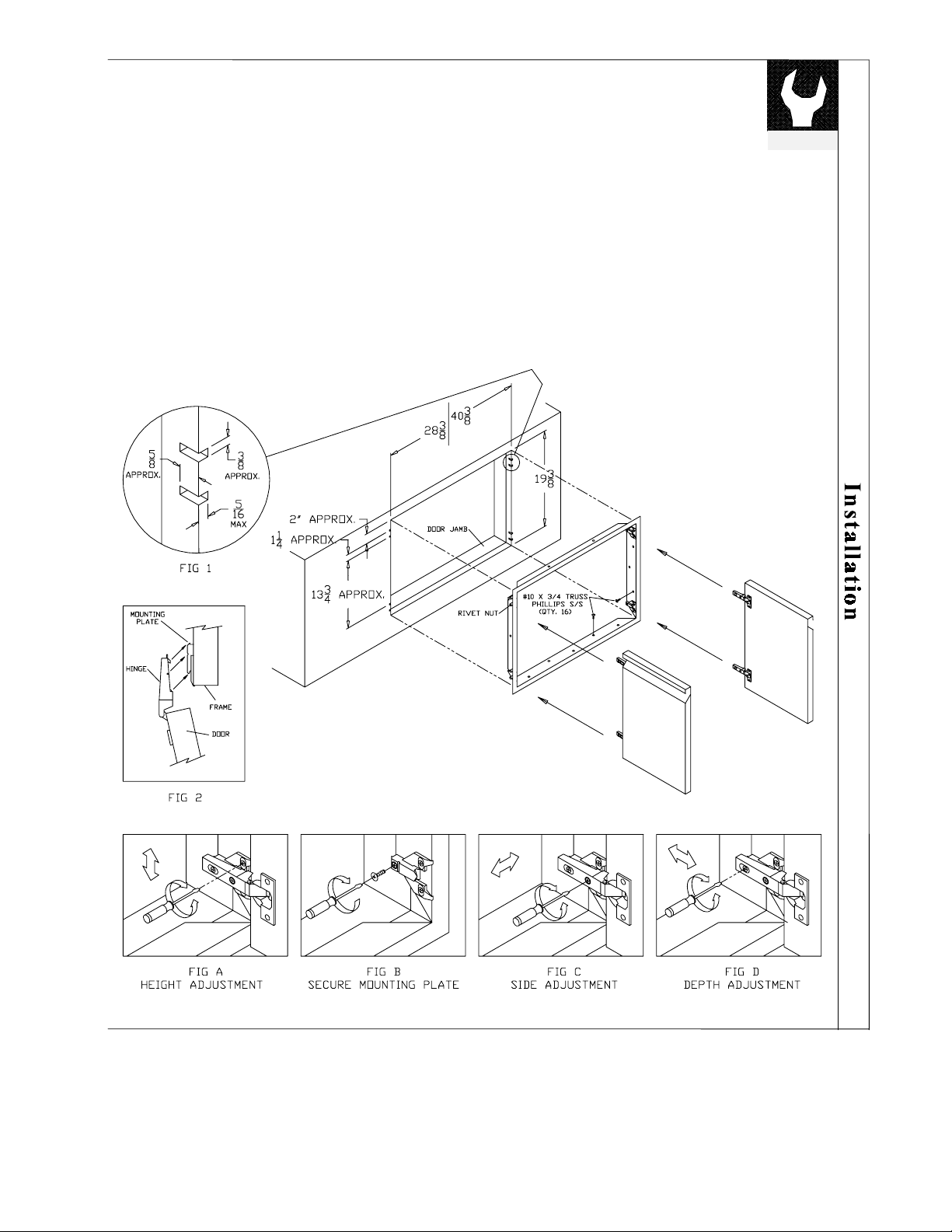
Installing Access Doors
Models DAD-30 and DAD-42
1. Provide cut out and door jamb with inside
dimensions as follows:
19 3/8” X 28 3/8” for DAD-30 and
19 3/8” X 40 3/8” for DAD-42
2. Check fitting of frame against cutout.
Mark location of rivet nuts.
3. Chisel material out to clear space for the
rivet nuts. (See figure 1)
4. Secure the steel frame with 16 screws of
type #10 X ¾ truss head phillips S/S.
5. Attach doors to frame. (See figure 2)
6. Adjust doors as follows:
a) For height adjustment, loosen the two screws
attached to each mounting plate. (See figure
A)
b) Snap off hinge and secure mounting plate
with #6 X 1 flat phillips S/S. (See figure
B).
c) For side adjustment turn screw to increase or
decrease door overlay. (See figure C)
d) For depth adjustment, loosen screw, adjust
door to desired position and retighten screw.
(See figure D)
installation
©2005 Maytag Services 16025981 B–13
Page 33
installation
Adjustments and Efficiency
INSTALLATION OF YOUR DYNASTY GRILL
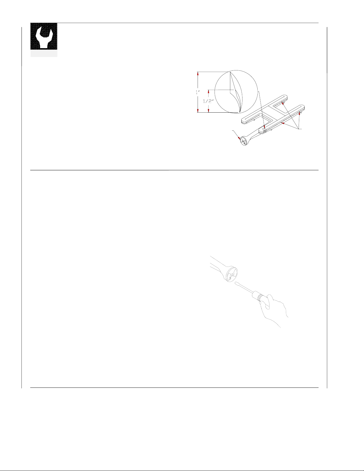
Prior to shipment each burner is tested and adjusted at the
factory. Due to variations in the location, conditions, gas
supply or when converting from one gas to another,
readjustment of the burners may be necessary.
The flames of the burners (except the rotisserie burners)
should be visually checked and compared to that of the
figure on the right.
Flames should be blue and stable with no yellow tips,
excessive noise or lifting. If any of these conditions exist,
check if dirt, debris, spider webs, etc. block the air shutter or
burner ports. Proceed with air shutter adjustment.
Air Shutter Adjustment
A sheet metal disk known as an air shutter governs the
amount of air entering the burner. It is locked in place by a
setscrew, which must be loosened with a screwdriver for
adjusting.
1. To access the grill burner air shutters, set all the knobs
in the off position. Make sure the grill is cool.
2. Remove the grill racks and the briquette trays complete
with the briquettes.
3. Slide out and remove any smoker drawer.
4. Light the burner. If the flame is yellow, it indicates that
there is insufficient air. If the flame is noisy and tends
to lift away from the burner, it indicates too much air.
Refer to step 6 for adjustments.
5. For the following instructions be careful as the burner
may be very hot. Wait until it cools down. Grasp the
burner and lift it up and slightly to the rear of the unit.
Angle the burner sideways carefully clearing the orifice
and the opening at the front. Remove the burner.
6. With a screwdriver, loosen the lockscrew on the face of
the air shutter and adjust the air shutter clockwise to
allow more air if the flame is yellow. Adjust the air
shutter counter-clockwise if the flame is noisy and tends
to lift.
(continued next page)
(continued)
#+45*766'4
PROPER GRILL BURNER FLAME HEIGHT
$740'4
21465
B–14 16025981 ©2005 Maytag Services
Page 34
Air Shutter Adjustment
(continued)
7. Reinstall the burner. Turn on and observe the flame.
When flame is as described in “Adjustments and
Efficiency” turn the burner off. Be sure to tighten air
shutter setscrews when finished.
8. Repeat procedure for each burner requiring
adjustment.
9. Once adjusted, reverse steps to reassemble.
Low Setting Adjustment
Grill and Open Burners
The valves on your Dynasty grill feature an adjustable
low setting. Due to fluctuations in gas pressure, heating
value or gas conversion, you may feel it necessary to
increase or decrease gas flow in the low position.
1. Begin by lighting the burner.
2. Turn the control knob to the lowest setting, all the
way counter clockwise. The arrow will stop between
MED and LOW.
3. Remove knob.
4. Hold the valve shaft with a pair of pliers and insert a
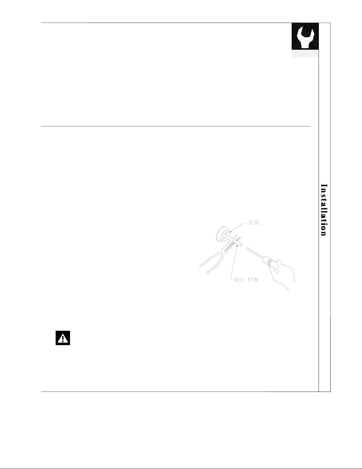
thin, flat tipped screwdriver into the shaft. While
viewing the burner, adjust to a minimum stable
flame.
5. WARNING! Look for stability in the low flame
setting. A too small burner flame may go out or be
extinguished easily. Unburned gas can then escape
creating a hazardous condition.
installation
NOTE: It is normal to hear a popping sound
when the burners are first turned OFF.
©2005 Maytag Services 16025981 B–15
Page 35

installation
INSTALLATION OF YOUR DYNASTY GRILL
(continued)
Leak Testing
Perform a leak test at least once each year whether the gas supply cylinder has
been disconnected or not. In addition, anytime the gas cylinder is connected to
the regulator or any part of the gas system is disconnected or replaced, conduct the
leak testing. This applies to natural gas as well as LP Gas.
As a safety precaution, remember to always leak test your grill outdoors in a wellventilated area. Never smoke or permit sources of ignition in the area while doing
a leak test. Do not use a flame, such as a lighted match to test for leaks. Use only
a leak testing solution as specified below.
Leak Testing Procedure
1. Prepare a leak testing solution of sudsy water by
mixing in a spray bottle half liquid soap and half
water.
2. Check and make sure all the control knobs are in the
OFF position.
3. Turn cylinder valve knob counter clockwise one turn
to open.
4. Apply leak-testing solution by spraying on joints of
the gas delivery system.
5. Blowing bubbles in the soap solution indicates that a
leak is present.
6. Stop a leak by tightening the loose joint or by
replacing the faulty part with a replacement part
recommended by the manufacturer. Do not attempt
to repair the cylinder valve if it should become
damaged. The cylinder must be replaced.
(continued next page)
B–16 16025981 ©2005 Maytag Services
Page 36
Leak Testing Procedure
(continued)
7. If you are unable to stop a leak, shut off the gas
supply at the cylinder valve. Remove the cylinder
from the grill. Call an authorized gas appliance
service technician or LP gas dealer. Do not use the
appliance until the leak is corrected.
8. Push in and turn any control knob to release pressure
in the hose and manifold.
9. Turn off the control knob.
Installing the Heat Deflector
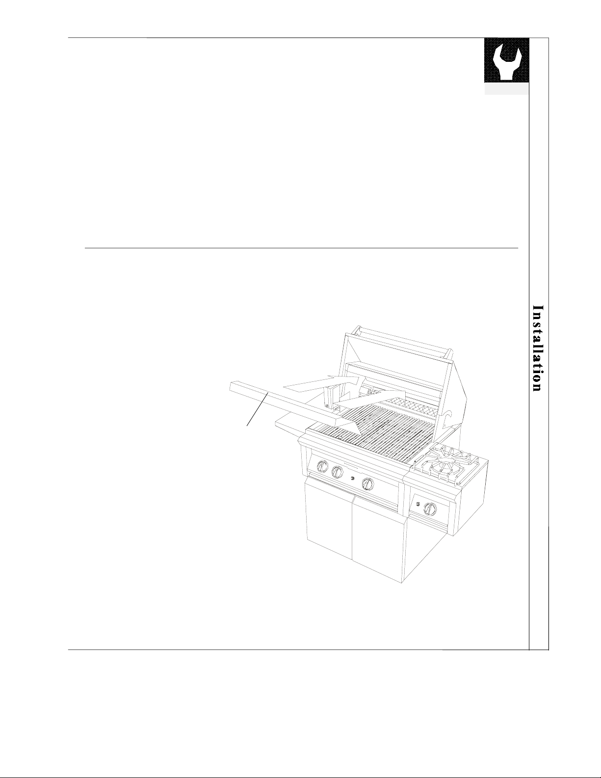
The Heat Deflector should be fully inserted in its
position, as shown, before using the grill.
installation
HEAT
DEFLECTOR
©2005 Maytag Services 16025981 B–17
Page 37
g
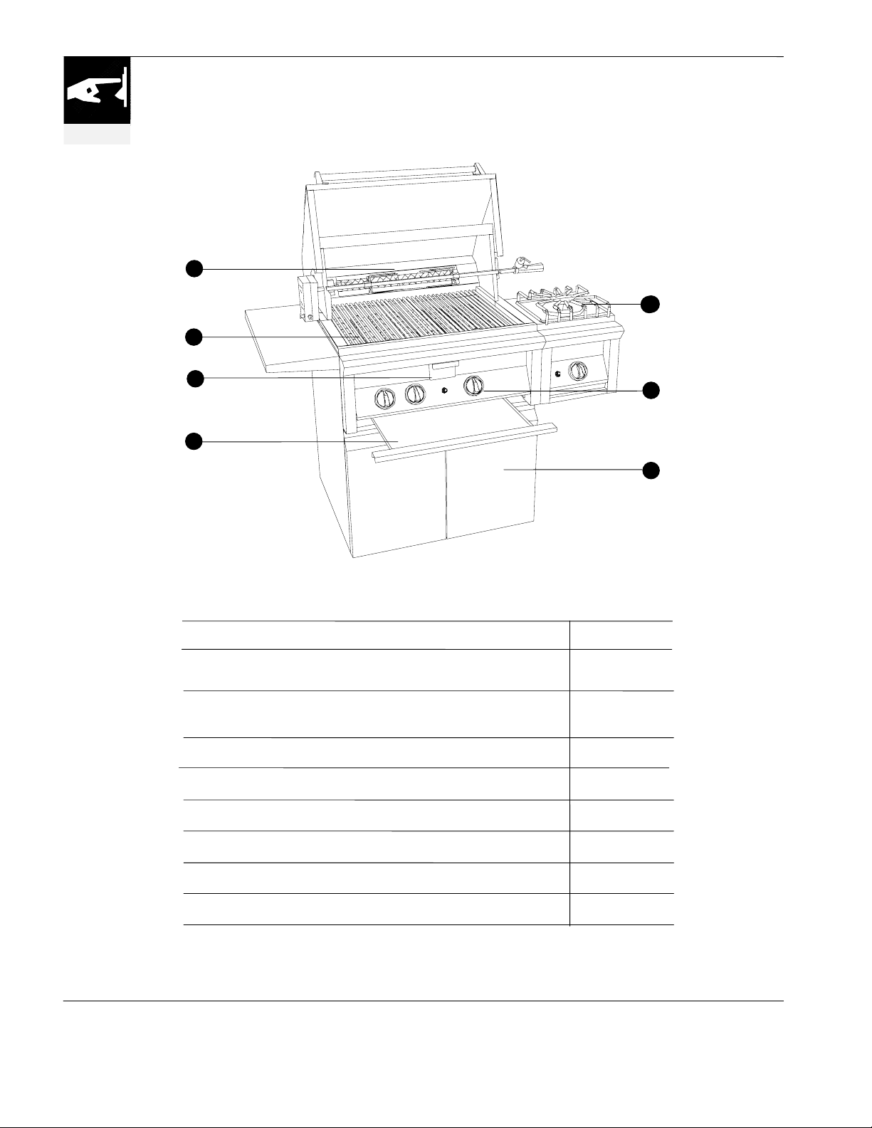
FEATURES OF YOUR GRILL
operation
4
5
3
6
2
1
7
Feature Index See page
1 Grill
2 Top Burners
3 Smoker Drawer
4 Rotisserie
5 Grill Racks
6 Drip Tray
7 Exterior Surfaces
8 Questions?
Operation
Cleaning
Operation
Flame Hei
ht
Operation
Operation
Cleaning
Cleaning
Cleaning
Easy Troubleshooting Guide
18-20
32-35
24-25
25
21
22-23
32
33
33
36-37
B–18 16025981 ©2005 Maytag Services
Page 38
Spiders and other insects can nest in the burners of the grill and block the gas and
airflow to the burner ports. This creates a dangerous condition that can result in a
fire from behind the valve panel. It is good practice to inspect the burners for
blockage and clean them regularly; in addition, such inspection and cleaning is
absolutely necessary if any of the following conditions exists:
a) Smell of gas in conjunction with a yellow flame.
b) Grill does not heat completely.
c) Grill heats unevenly.
In case any of the above conditions is present, turn off the grill immediately; after
allowing it to cool, inspect and clean the burners as described on pages 34-35 of
this manual.
SPIDERS AND OTHER INSECTS WARNING…
safety
BEFORE USING YOUR GRILL...
Prior to turning the gas on, inspect the gas supply piping or hose. Make sure only
the supplied hose and regulator are being used. If signs of abrasion, cuts wear and
tear, or other damage are noticed on the hose, it should be replaced. Contact your
local Dynasty dealer for replacement parts.
©2005 Maytag Services 16025981 B–19
Page 39
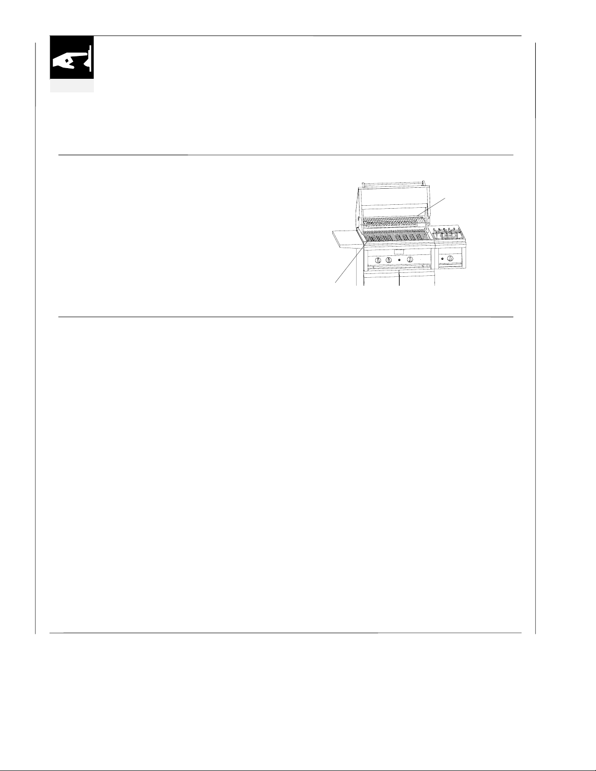
operation
Your Dynasty grill consists of a set of burners, a bed of
USING YOUR GRILL
ceramic briquettes and a heat retaining cooking rack.
Each burner is rated at 25,000 BTU. The grill burners,
encompassing the entire cooking area, are
side ported to minimize blockage for falling grease
and debris. Above the burners are stainless steel trays
which support the ceramic briquettes and protect the
burner ports from blockage.
Grilling
Grilling requires high heat for searing and proper
browning. Most foods are cooked at the HI heat
setting for the entire cooking time. However, when
grilling large pieces of meat or poultry, it may be
necessary to turn the heat to a lower setting after the
initial browning. This cooks the food through without
burning the outside. Foods cooked for a long time or
basted with a sugary marinade may need a lower heat
setting near the end of the cooking time. Warming
rack is used for defrosting or for keeping food warm
GRILL RACK
while grilling.
Grilling Hints
x The doneness of meat, whether rare, medium, or well done, is affected to a
large degree by the thickness of the cut. Expert chefs say it is impossible to
have a rare doneness with a thin cut of meat.
x The cooking time is affected by the kind of meat, also by the size and the
shape of the cut, the temperature of the meat when cooking begins, and the
degree of doneness desired.
x When defrosting meats it is recommended that it be done overnight in the
refrigerator as opposed to a microwave. This generally yields a juicer cut of
meat.
x Use a spatula instead of tongs or a fork to turn the meat. A spatula will not
puncture the meat and let the juices run out.
x To get the juiciest meats, add seasoning or salt after the cooking is finished
and turn the meat only once (juices are lost when the meat is turned several
times). Turn the meat just after the juices begin to bubble to the surface.
x Trim any excess fat from the meat before cooking. To prevent steaks or chops
from curling during cooking, slit the fat around the edges at 2-inch intervals.
x Do not leave the grill unattended while cooking.
WARMING RACK
B–20 16025981 ©2005 Maytag Services
Page 40
Operating The Grill
Make sure all burner controls are off. Do not attempt to
light the burners if the smell of gas is present.
For LP units, check the connection with a soap and water
solution after attaching the hose. Make sure there is gas
in the tank and it is sitting upright.
1. Make sure the drip tray is in place.
2. Light the grill burners using the instructions below.
operation
3. Turn the control knob to HI and preheat the grill for
15 minutes. The top cover is to be closed during the
appliance preheat period.
4. Place the food on the grill and cook to the desired
doneness. Adjust heat setting, if necessary. The
control knob may be set to any position between HI
and LOW
5. Allow the grill to cool and clean the drip tray after
each use.
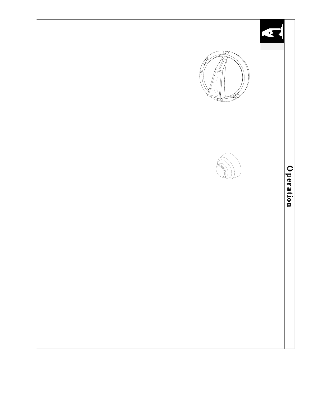
Lighting The Grill Burners
1. Open the hood.
2. Keep your face as far away from the burners as
possible.
3. Push in and turn counter clockwise the gas control
knob for the grill to the LITE or HI position.
4. Press the push button igniter next to the control knob.
A multiple clicking noise should be heard from the
igniter indicating a spark is being provided to the
burner.
BURNER CONTROL KNOB
PUSH BUTTON IGNITER
5. Listen for the “Woosh” sound. If the burner does not
light on the first try, repeat immediately.
6. If the burner does not light after 5 seconds, turn the
control knobs to the OFF position. Wait 5 minutes
until the gas clears before attempting to light it again.
(continued next page)
©2005 Maytag Services 16025981 B–21
Page 41

operation
USING YOUR GRILL
Lighting The Grill Burners
(continued)
7. Repeat the procedure or try “Manual Lighting
procedure” below.
8. Upon successful lighting, repeat the process on the
other burners you wish to light.
9. To shut off burners push in knob and turn to OFF. It
is normal to hear a popping sound when the burners
are turned off.
Manually Lighting The Grill Burners
1. Open the hood.
2. Remove the grates over the burners you wish to light.
3. If you have just attempted to light the burner with the
push button igniter, allow 5 minutes for any
accumulated gas to dissipate.
4. Keep your face as far away from the burners as
possible.
5. Pass a lit, long stem match through one of the small
briquette tray holes and position it near the burner
ports.
6. Push in and turn counter clockwise the grill’s gas
control knob to the LITE position.
7. Listen for the “Woosh” sound. If the burner does not
light after 5 seconds, turn the control knobs to the
OFF position. Wait 5 minutes until the gas clears
before attempting to light it again.
8. If the burner does not light after several attempts see
Troubleshooting Guide on pages 36-37.
9. Upon successful lighting, repeat the process on the
other burners you wish to light.
(continued)
B–22 16025981 ©2005 Maytag Services
Page 42
The smoker drawer consists of a stainless steel slide out drawer positioned near
the front just above the grill burners. It is designed for easy use.
After deciding which wood chips to use (see chart below), soak them thoroughly
in water, then place them into the drawer. Light the grill burner next to the
smoker box and leave on HIGH setting for 5 to 10 minutes to initiate smoking.
Lower the flame to appropriate cooking setting, then place meat on the grill. The
specially designed smoker will smoke the wood while the grill cooks the food.
Keeping the grill lid closed as much as possible will maximize the smoking effect.
If the wood chips do flame up, add a small amount of water to extinguish the
flame. This should be done carefully by pulling the drawer out slightly. Use
caution when adding water to a hot drawer to avoid steam burns, and never
completely remove a hot drawer.
The drawer may also be filled with water to produce steam. Whether smoking or
steaming the lid should remain closed as much as possible to maximize the effect.
During extended roasting periods it is normal to add fresh wood chips to the
drawer several times.
USING THE SMOKER DRAWER
operation
Wood Type
Alder
Maple
Apple
Hickory
Mesquite
Oak
Pecan
Grapevine
Characteristics and Use
A medium, tart smoke taste. Superb on salmon and other fish, chicken or game.
Sweet, hearty smoke flavor. Best with fish, jerky or bacon.
A light, sweet flavor. Superb with poultry, ham or sausage.
Heavy smoke flavor. Best with beef, pork or game.
A light smoke flavor. Best with fish, poultry or beef.
Heavy smoke flavor. Best with beef, lamb or pork.
A rich, sweet, versatile flavor. Can be used with anything.
A strong smoke flavor. Best with beef or poultry.
©2005 Maytag Services 16025981 B–23
Page 43
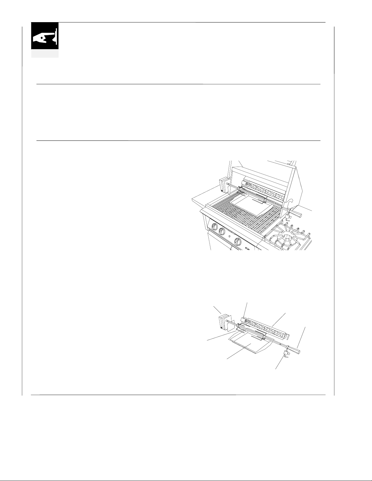
operation
The rotisserie burner is an infrared type, which
provides intense searing radiant heat. Preferred by
USING YOUR ROTISSERIE
heat is ideal for searing in the natural juices and
nutrients found in quality cuts of meat.
professional chefs over other methods, this intense
Cooking with the Rotisserie
The rotisserie system is designed to cook items from the back using infrared heat. The
location of the burner allows the placement of a rotisserie-basting pan (included)
beneath the food to collect juices and drippings for basting and gravy. To flavor the
contents of the basting pan, you can add herbs, onion, garlic, or spices. Hams are
especially good with the addition of pineapple slices and brown sugar to the basting pan.
Operating The Rotisserie
1. To load the rotisserie rod, hold the handle firmly
while sliding one of the fork assemblies (prongs
facing away from the handle) onto the rod. Push the
rod through the center of the food, then slide the
other holder (prongs toward the food) onto the rod.
Center the meat on the rod and push the fork
assemblies firmly together. Tighten the
thumbscrews. To secure any loose portions of your
meat, use butcher string (never use nylon or plastic
string). Place basting pan under the food to collect
the drippings.
2. To use the rotisserie, first mount the motor on the left
side of the grill. Place securely onto support bracket.
3. The rod of the rotisserie system is assembled into the
motor by placing the pointed end into the motor and
resting the threaded end on the support at the side of
the grill. Once the rod is pushed as far as possible
into the motor, the grooved end of the rod should rest
on the right side bracket.
4. If necessary, to offset unbalanced loads, slide the
counter weight on to the rod. With the counter
weight loose, allow the loaded rod to rotate and come
to a stop. Now rotate the counter weight above the
rod in a vertical position and tighten the thumbscrew.
You can slide the counter weight away from or closer
to the rotisserie rod as needed for balanced operation.
5. Light rotisserie burners following instructions on
page 23. Once lit, the rotisserie burner will reach
cooking temperature in about 1 minute. The
orange/red glow will even out in about 5 minutes.
MOTOR
FORK
BASTING PAN
ROTISSERIE SET UP
IGNITER
I.R. BURNER
ROD HANDLE
COUNTER WEIGHT
B–24 16025981 ©2005 Maytag Services
Page 44
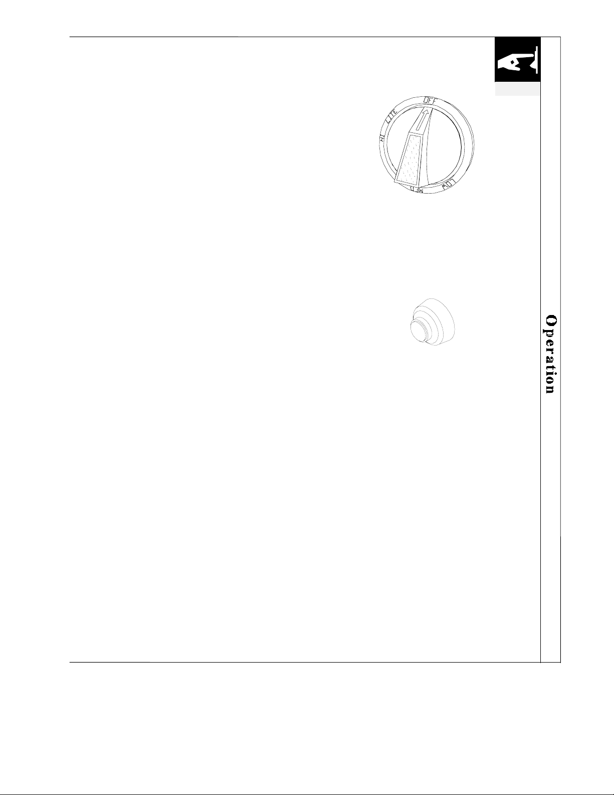
Lighting The Infrared or Rotisserie Burner
1. Open the hood.
2. Push in and turn counter clockwise the gas control
knob for the IR (infrared) burner to the HI position.
This is the knob farthest to the left. On units with
two IR burners, the control knob for the right IR
burner is the knob farthest to the right.
3. Press the push button igniter next to the IR burner
knob. A multiple clicking noise should be heard from
the igniter indicating a spark is being provided to the
burner.
4. If the burner does not light on the first try, repeat
immediately.
5. If the burner does not light within 5 seconds, turn the
control knob to the OFF position. Wait 5 minutes
until the gas clears before attempting to light it again.
6. Repeat the procedure or try “Manual Lighting
procedure” as shown below.
7. Upon successful lighting, repeat the process on any
other available IR burner you may wish to light.
Wait 5 minutes before re-lighting a HOT rotisserie
burner.
BURNER CONTROL KNOB
PUSH BUTTON IGNITER
operation
Manually Lighting The Infrared or Rotisserie
Burner
1. Open the hood.
2. Push in and turn counter clockwise the gas control
knob for the IR (infrared) burner to the HI position.
3. Hold a lit match next to the burner ports.
4. If the burner does not light within 5 seconds, turn the
control knob to the OFF position. Wait 5 minutes
until the gas clears before attempting to light it again.
5. If the burner does not light after several attempts see
troubleshooting guide on page 37.
6. Upon successful lighting, repeat the process on any
other available IR burner you may wish to light.
Wait 5 minutes before re-lighting a HOT rotisserie burner.
©2005 Maytag Services 16025981 B–25
Page 45
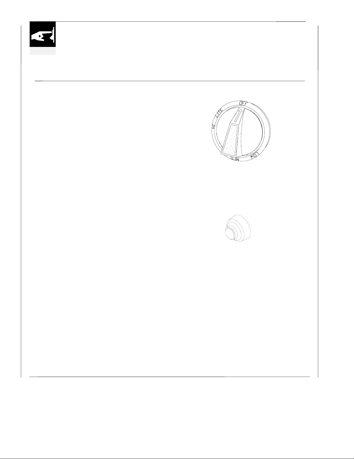
operation
Your Dynasty grill has optional top burners equipped
USING THE TOP BURNERS
with push button igniter for lighting.
Lighting The Open Burners
1. Remove the burner cover, if any, or any cooking
utensils from the burner grate. Caution: The burner
cover may be hot if the grill burners are in
operation.
2. Push in and turn counter clockwise the gas control
knob for the burner to the LITE position.
3. Press the push button igniter next to the control knob.
A multiple clicking noise should be heard from the
igniter indicating a spark is being provided to the
burner.
4. If the burner does not light on the first try, repeat
immediately.
5. If the burner does not light after 5 seconds, turn the
control knobs to the OFF position. Wait 45 seconds
until the gas clears before attempting to light it again.
6. Repeat the procedure or try “Manual Lighting
procedure” below.
7. Upon successful lighting, repeat the process on any
other available burner you may wish to light.
BURNER CONTROL KNOB
PUSH BUTTON IGNITER
Manually Lighting The Open Burners
1. Remove the burner cover, if any, or any cooking
utensils from the burner grate. Caution: The burner
cover may be hot if the grill burners are in
operation.
2. Push in and turn counter clockwise the gas control
knob for the burner to the LITE position.
3. Hold a lit match next to the burner ports.
(continued on next page)
B–26 16025981 ©2005 Maytag Services
Page 46
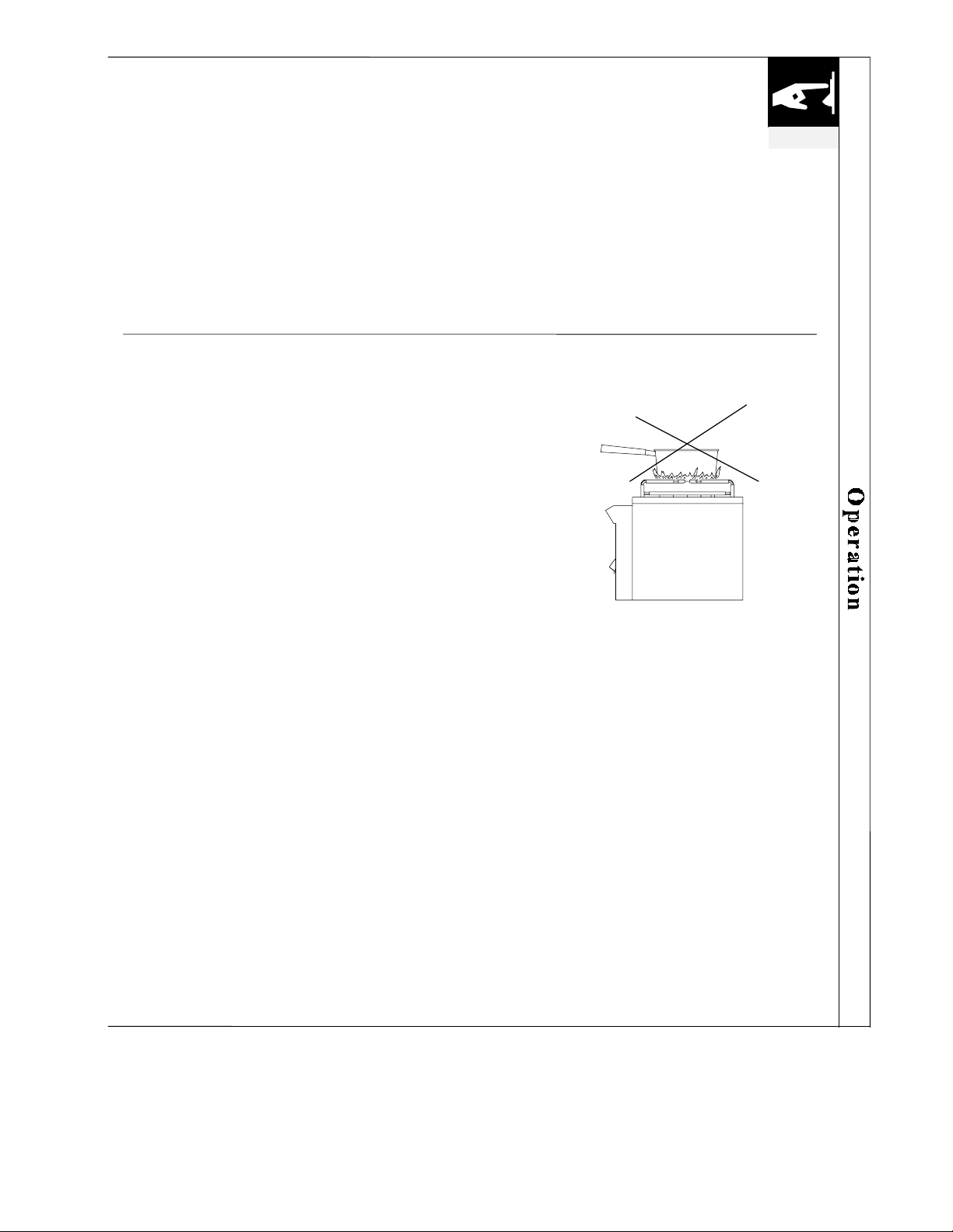
Manually Lighting the Open Burners
(continued)
4. If the burner does not light after 5 seconds, turn the
control knobs to the OFF position. Wait 45 seconds
until the gas clears before attempting to light it again.
5. If the burner does not light after several attempts see
troubleshooting guide on pages 36-37.
6. Upon successful lighting, repeat the process on any
other available burner you may wish to light.
operation
Flame Height
The correct height of the flame depends on the size and
material of the utensil being used, the food being cooked
and how much liquid is in the utensil.
Here are some basic rules for selecting the flame height.
x The flame should never extend beyond the bottom of
the pan.
x Utensils, which conduct heat slowly (such as glass-
ceramic) should be used with a low or medium flame
unless you are cooking with a large amount of liquid.
x When boiling, adjust the flame to the size of the
cookware until boiling begins. Then lower flame
height to the minimum needed to maintain a gentle
boil. Foods cook just as fast at a gentle boil, as they
do at a vigorous boil.
©2005 Maytag Services 16025981 B–27
Page 47
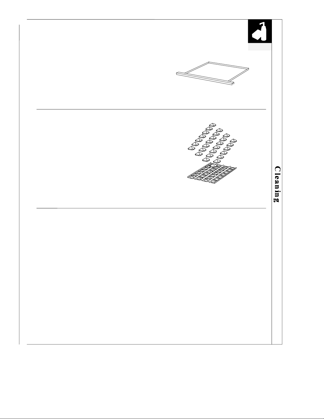
N
Cleaning the Drip Trays
The full width drip tray will collect grease from the grill
section. It should be emptied and cleaned out after
every use. Allow the pan and its contents to cool before
attempting to clean. Slide out the tray and wipe it clean.
By cleaning the grease from the pan after every use you
avoid the possibility of a grease fire. Make sure the drip
tray is fully inserted back into its track before using the
grill.
Cleaning the Ceramic Briquettes and
Radiant Trays
It is not necessary to remove the briquettes from the
radiant trays for cleaning. They burn themselves clean
during the next cooking operation or if desired you can
burn clean them by lighting the grill and letting it burn
on high for about 30 minutes.
Periodically the briquette trays should be removed and
any debris cleaned out. How often you use the grill
and the amount and type of food cooked will
determine when it is necessary to clean the briquette
trays. Never attempt to handle a hot briquette tray.
DRIP TRAY
BRIQUETTES AND TRAY
cleaning
Cleaning the Stainless Steel
Your Dynasty grill is made of all welded #304 stainless steel. This is a nonrusting and non-magnetic stainless steel.
There are many different stainless steel cleaners available. Always use the mildest
cleaning procedure first, scrub in the direction of the grain; use more harsh
methods only when necessary.
To touch up noticeable scratches in the stainless steel, sand very lightly with dry
100 grit emery paper in the direction of the grain.
Specks of grease can gather on the surface of the stainless steel and bake on to the
surface and give the appearance of rust. For removal use an abrasive pad (like
Scotch Brite) in conjunction with a stainless steel cleaner.
ever use steel wool to clean the grill and never clean the stainless when it is hot.
Be especially careful when cleaning the polished highlights on your grill and
scrub only when absolutely necessary.
B–28 16025981 ©2005 Maytag Services
Page 48
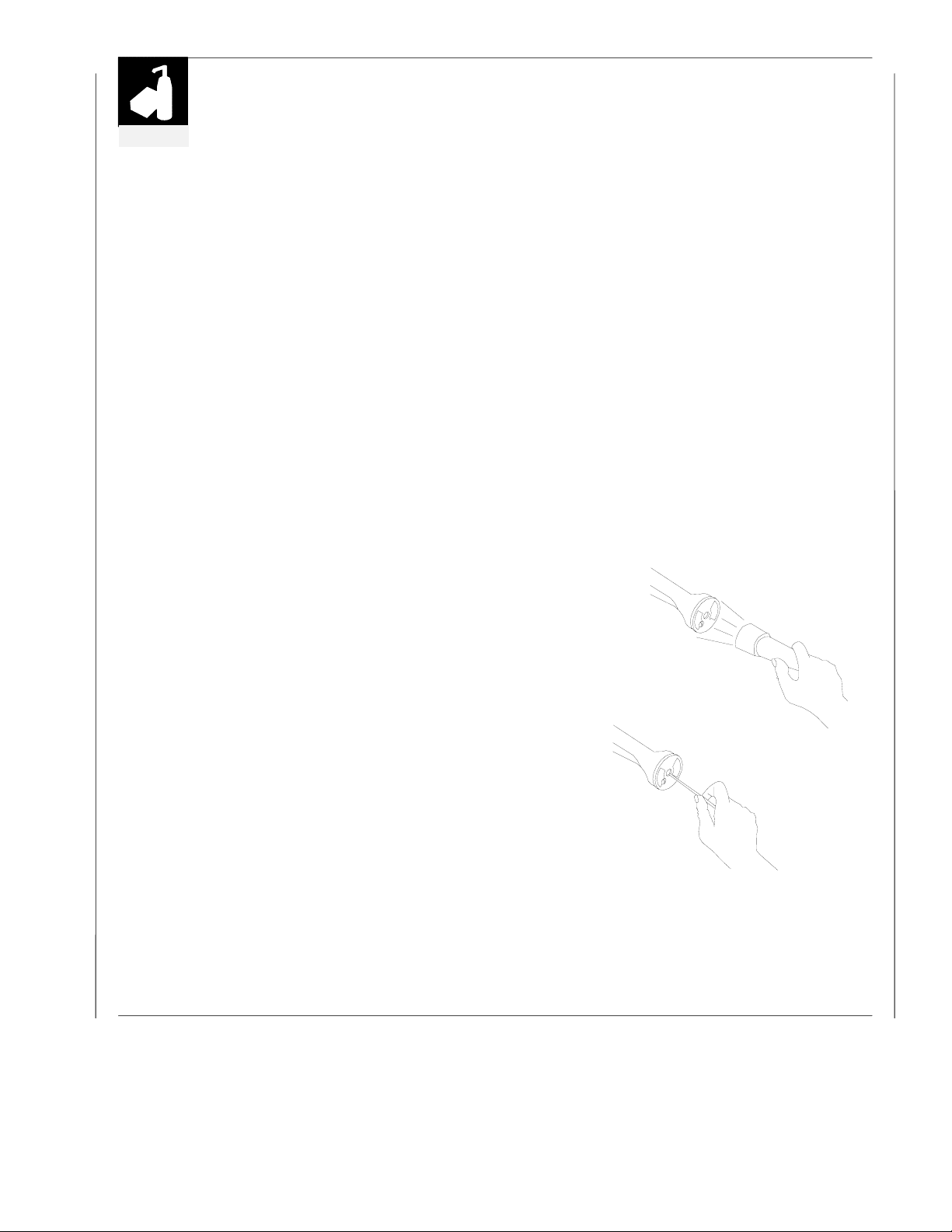
cleaning
Cleaning the Grill Burners
The grill burners should be cleaned thoroughly before using your grill
after long periods of storage and monthly during regular use.
1. Be sure the gas supply is off and the knobs are in the OFF position.
Make sure the grill is cool.
2. Remove the grill racks and the briquette trays complete with the
briquettes.
3. Slide out and remove any smoker drawer.
4. Grasp the burner and lift it up and slightly to the rear of the unit.
Angle the burner sideways carefully clearing the orifice and the
opening at the front. Remove the burner.
5. Repeat steps above with each of the burners in your unit.
6. Clean the exterior of the burner with a brass bristle brush. Clear any
clogged ports with a straightened paper clip. Shake out any debris
through the air shutter.
7. Using a flashlight, as shown, inspect the interior of the burner for any
blockages. If any are found, remove them with a straightened metal
wire coat hanger as shown. Again shake out any debris through the
air shutter.
8. Before replacing the burners, check grill bottom for any accumulation
of grease, carbon and burnt food. Clean bottom as described below.
9. Replace the burner by sliding the air shutter over the orifice, centering
the burner on the orifice hole. When properly centered, the burner
rear legs will fit into the square mounting holes of the burner support
rail. It is extremely important to properly center the burner on the
orifice. Be careful not to disturb the air shutter position. Lower the
burner on to the support rail making sure it is level and does not rock.
10. Replace the briquette tray and briquettes, again making sure the tray is
level and stable.
11. Replace the grill racks.
12. Light all burners and check for flame characteristics as described on
Adjustments and Efficiency section on page 12.
WARNING: Never spray aerosol cleaners onto or around a hot grill;
The aerosol propellant or cleaner may ignite or explode causing serious
injury.
CLEANING AND MAINTENANCE
(continued)
©2005 Maytag Services 16025981 B–29
Page 49
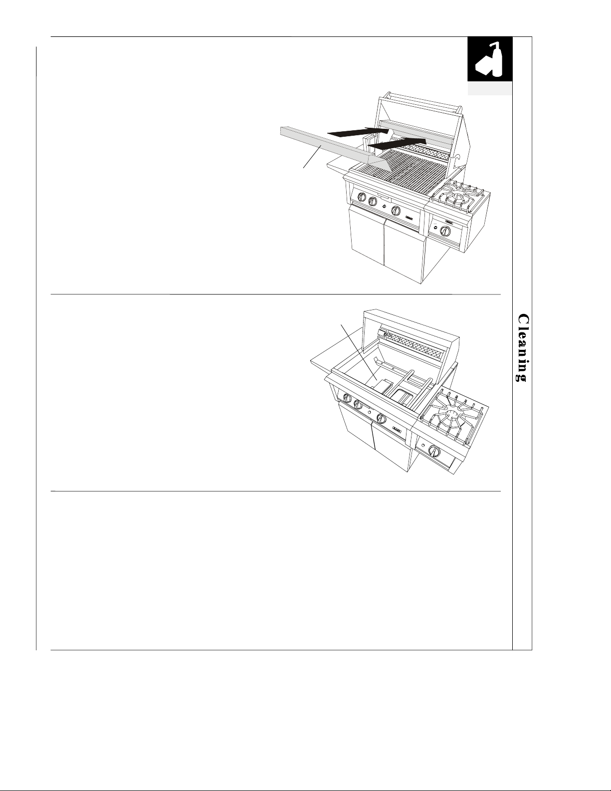
cleaning
Cleaning the Heat Deflector
The heat deflector will collect grease and food
residuals. It should be removed and cleaned after
every use.
When removing the heat deflector, use care to avoid
chipping its ceramic surface. Wash with a mild
cleaner/degreaser, rinse and dry. Make sure the heat
deflector is fully inserted back in its position before
using the grill.
Cleaning Firebox Bottom
Before you put back the grill burners in step 9 of
Cleaning the Grill Burners, look to see if you have an
accumulation of carbon and burnt food on the bottom.
If so, use a spatula or scraper and push all the carbon
to the front and into the drip pan to collect and dispose.
HEAT
DEFLECTOR
FIREBOX
BOTTOM
Replacing Igniter Batteries
The batteries of the igniter should be replaced when a clicking sound is no longer heard.
1. Be sure the gas supply is OFF and the knobs are in the OFF position.
2. Turn igniter rubber cap counterclockwise by a 1/4 turn and pull it out.
3. Remove old battery and replace with new one. Be sure positive end of battery is inserted first.
4.
Replace igniter rubber cap by pushing it in and rotating it clockwise.
B–30 16025981 ©2005 Maytag Services
Page 50
questions
QUESTIONS?
USE THIS EASY TROUBLESHOOTING GUIDE
PROBLEM
GRILL WILL NOT IGNITE
WHEN THE PUSH BUTTON
IGNITER IS PRESSED
BURNER FLAME IS YELLOW
IN CONJUNCTION WITH THE
SMELL OF GAS
WHAT TO DO
1. Remove the grill rack and the briquette tray. Watch the igniter tip as
you press the push button igniter. You should see a spark jump from the
igniter tip to the burner.
2. If there is a spark, is gas supplied to the burner and is the line purged of
air? Can you match light the burner? Do the other burners light?
3. Check the burner for blockage as described in Cleaning the Grill Burner
section on page 34.
4. Replace igniter battery as described on page 35; if there is no spark, call
for service.
5. Visually check the electrode and wire while pressing the push button
igniter. If a spark occurs anywhere but at the igniter tip, the igniter must
be replaced.
1. Check the burner for blockage as described in Cleaning the Grill Burner
section on page 34.
2. Check the air shutter for proper adjustment as described in Air Shutter
Adjustment section on page 12.
LOW HEAT WITH KNOB IN HI
POSITION
1. Is the fuel hose bent or kinked?
2. Is there an adequate gas supply available? Do any other gas appliances
at the location appear to be below normal?
3. Is the problem isolated to one burner? If so, proceed with burner
cleaning as described in Cleaning the Grill Burner section on pages 34
and 35.
4. Is the air shutter properly adjusted? See page 12 for adjusting
procedure.
5. Has the grill been preheated for 15 minutes with the lid closed?
©2005 Maytag Services 16025981 B–31
Page 51
questions
questions
PROBLEM PROBLEM
ROTISSERIE WILL NOT
ROTISSERIE WILL NOT
LIGHT
LIGHT
BURNER BLOWS OUT BURNER BLOWS OUT
TOO MUCH HEAT TOO MUCH HEAT
EXCESSIVE FLARE-UP EXCESSIVE FLARE-UP
NOTE: NOTE:
It is normal to hear a popping sound when the grill burners are first turned off. It is normal to hear a popping sound when the grill burners are first turned off.
WHAT TO DO WHAT TO DO
1. Is there a spark at the igniter? Check if the gap between the igniter
1. Is there a spark at the igniter? Check if the gap between the igniter
electrodes is between 1/8 to 3/16 of an inch. Replace igniter battery as
electrodes is between 1/8 to 3/16 of an inch. Replace igniter battery as
described on page 35. Can you match light the burner?
described on page 35. Can you match light the burner?
1. Check if burner is broken or fuel mixture is too lean. 1. Check if burner is broken or fuel mixture is too lean.
2. Check if gas supply is sufficient. Check if LP cylinder is empty. 2. Check if gas supply is sufficient. Check if LP cylinder is empty.
1. Damaged orifice or no orifice. Unauthorized regulator adjustment. 1. Damaged orifice or no orifice. Unauthorized regulator adjustment.
1. Dirty cooking grids. Overload from fatty meats or excessive cooking
1. Dirty cooking grids. Overload from fatty meats or excessive cooking
temperature.
temperature.
B–32 16025981 ©2005 Maytag Services
Page 52
g
A
YOUR DYNASTY OUTDOOR GRILL
WARRANTY
FULL ONE YEAR WARRANTY
- PARTS & LABOR
LIMITED TWO YEAR WARRANTY
- PARTS ONLY
TEN YEAR WARRANTY
LIMITED LIFETIME WARRANTY
For
one (1) year
normal home use will be repaired or replaced free of charge.
After the first year from original purchase date, parts which fail in normal
home use will be repaired or replaced free of charge for the part itself, with
the owner paying all other costs, including labor, mileage and transportation.
Any heavy duty Stainless Steel cooking grid which fails in normal household
use for a period of ten (10) years, will be repaired or replaced, free of charge
for the part itself, with the owner paying all other costs, including labor,
milea
e and transportation.
Any heavy duty Dynachrome
will be repaired or replaced, free of charge for the part itself, with the owner
paying all other costs, including labor, mileage and transportation.
The stainless steel body of your grill is warranted against structural
deterioration for a lifetime of normal household use. This applies only to the
actual body, and excludes all other costs, including labor and freight.
This warranty shall apply only to products manufactured and located in the United
States and Canada. Warranty labor shall be performed by an authorized DYNASTY
service agency or representative.
Warranty does not apply to damage resulting from abuse, accident, natural disaster,
loss of electrical power (for any reason) to the product, alteration, improper installation
or improper operation, unauthorized adjustments and calibrations performed on the
product, nor damage due to harsh chemicals (i.e., cleaning products improperly
applied).
Warrantor is not responsible for consequential or incidental damage. Warranty does
not apply to commercial usage, or to products with altered or removed serial numbers.
Owner shall be responsible for proper installation, providing normal care and
maintenance, providing proof of purchase upon request, and making the appliance
accessible for service.
Warrantor's liability on any claim of any kind, with respect to the goods or services
covered herein, shall in no case exceed the price of the goods or services or part
thereof which gives rise to the claim.
from the original retail purchase date, any part which fails in
TM
burner which fails in normal household use
WARRANTY SERVICE
ny implied warranties of merchantability and fitness applicable to the equipment are limited in duration to the period of coverage of this express
written warranty. This warranty grants specific legal rights to the purchaser. Other rights, which may vary from state to state, may also apply. Title to
the merchandise passes to the consignee upon acceptance by the carrier. After acceptance by the carrier, the merchandise travels at the risk of the
purchaser. In the event of freight damage do not refuse shipment. Advise the agent of the damage, and note the details of that damage on the freight
bill before any freight charges are paid. File a claim for damages with the freight agent. In the event of concealed damage (shipment arrives in
apparent good order, but upon unpacking is found to be damaged) immediately notify the freight agent in writing and retain a copy of the notification.
Part No. 2420100000 08/03
©2005 Maytag Services 16025981 B–33
Under the terms of this warranty, service must be performed by a factory authorized
DYNASTY service agent or representative. Service will be provided during normal
business hours. Labor performed at overtime or premium rates shall not be covered by
this warranty. To obtain warranty service, contact the dealer from whom the product
was purchased, an authorized DYNASTY service agent or DYNASTY. Provide model
and serial number and date of original purchase.
IMPORTANT: Retain original proof of purchase to establish warranty period.
DBQ-30 DBQ-42 DBQ-54 DSB-1 DSB-2 DBQ-30F DBQ-42F DFB
Page 53

Appendix C
C-1 16025981 © 2005 Maytag Services
Page 54
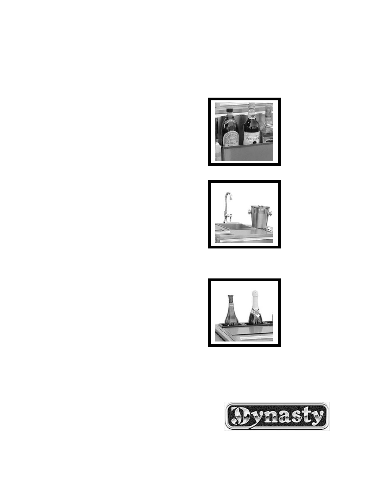
THE DYNASTY BAR TENDER
INSTALLATION, USE AND CARE MANUAL
MODELS:
DBTA-18
DBTA-30
DBTA-30F
© 2005 Maytag Services 16025981 C-2
Page 55
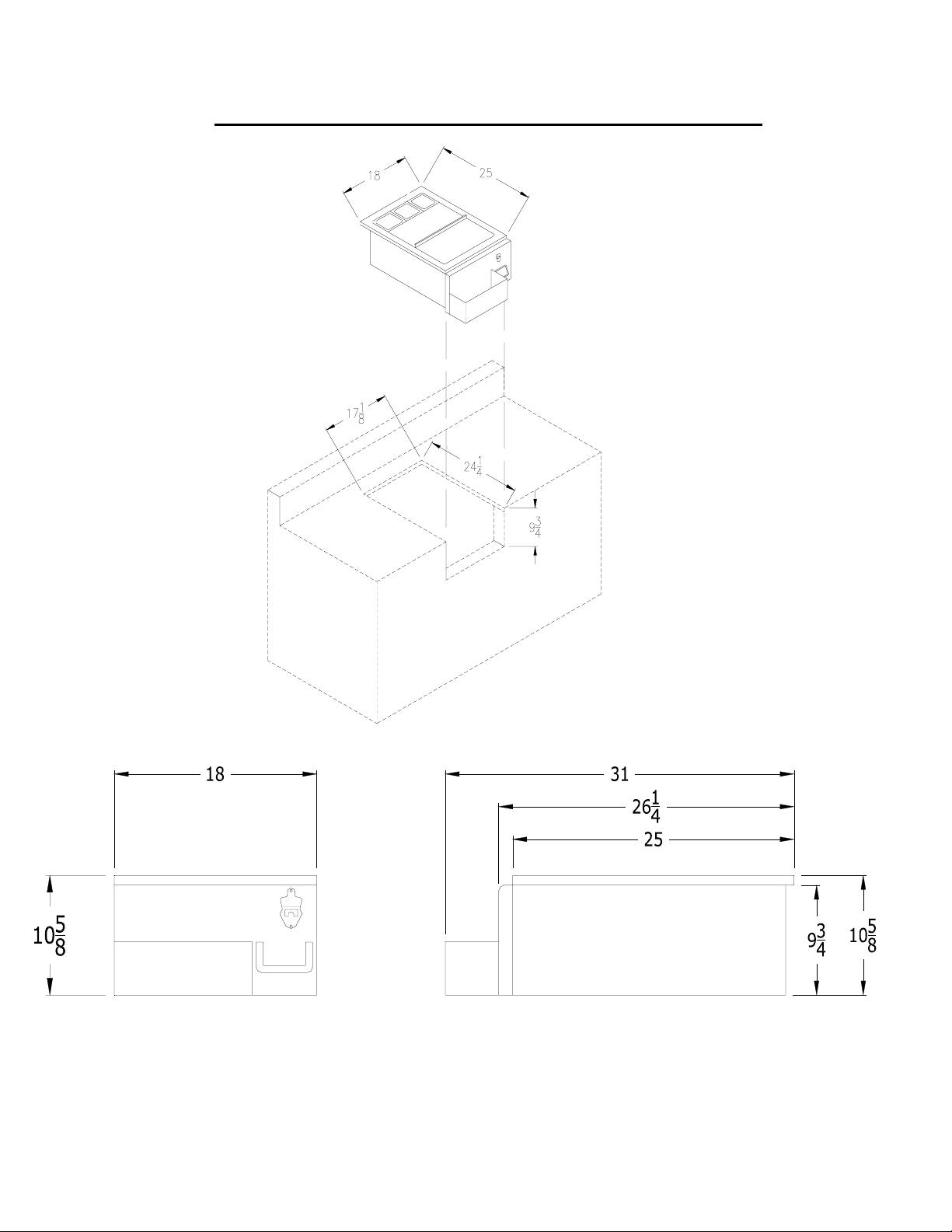
DBTA-18
DYNASTY 18” BUILT-IN BAR TENDER
DBTA-18
C-3 16025981 © 2005 Maytag Services
Page 56
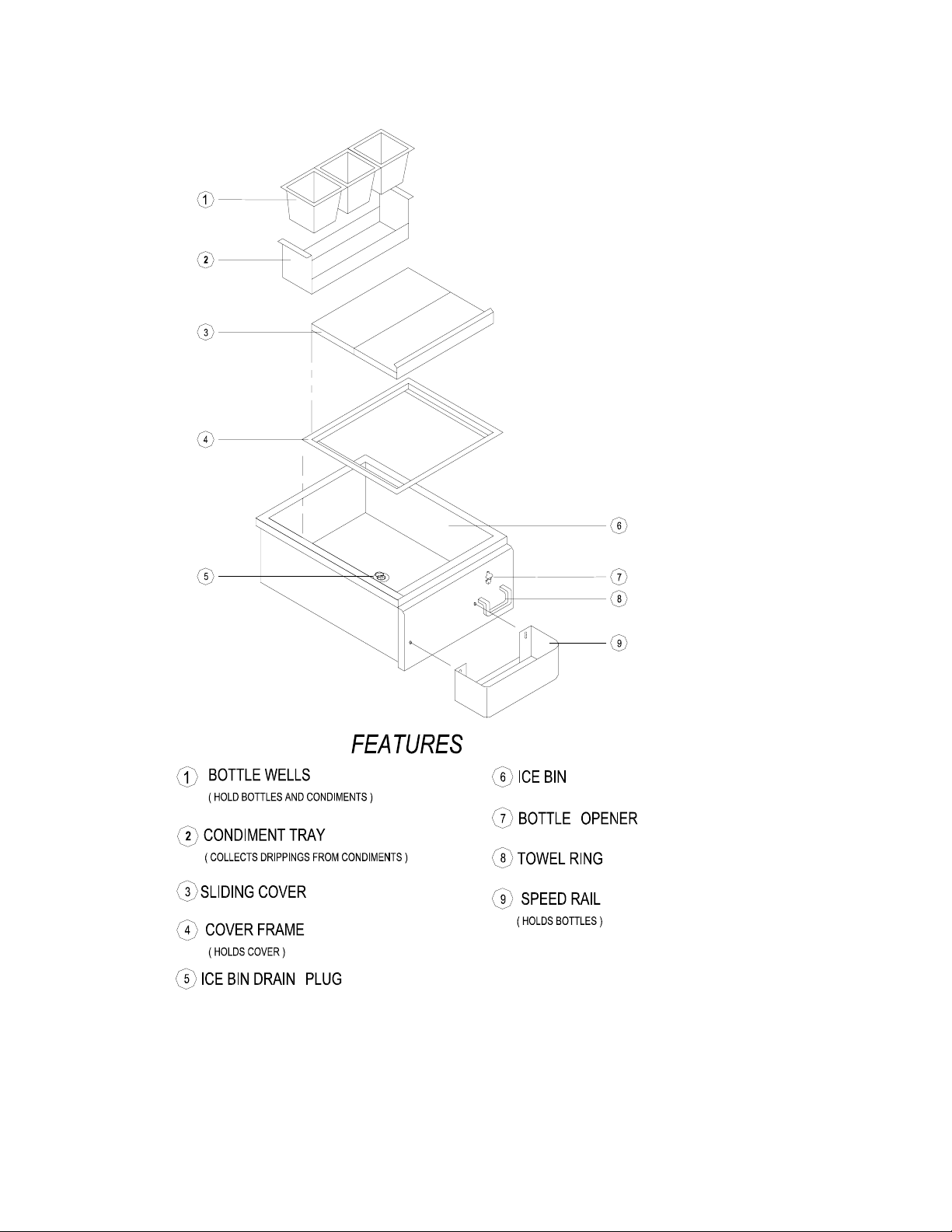
DYNASTY 18” BUILT-IN BAR TENDER
DBTA-30
DYNASTY 30” BUILT-IN BAR TENDER
© 2005 Maytag Services 16025981 C-4
Page 57
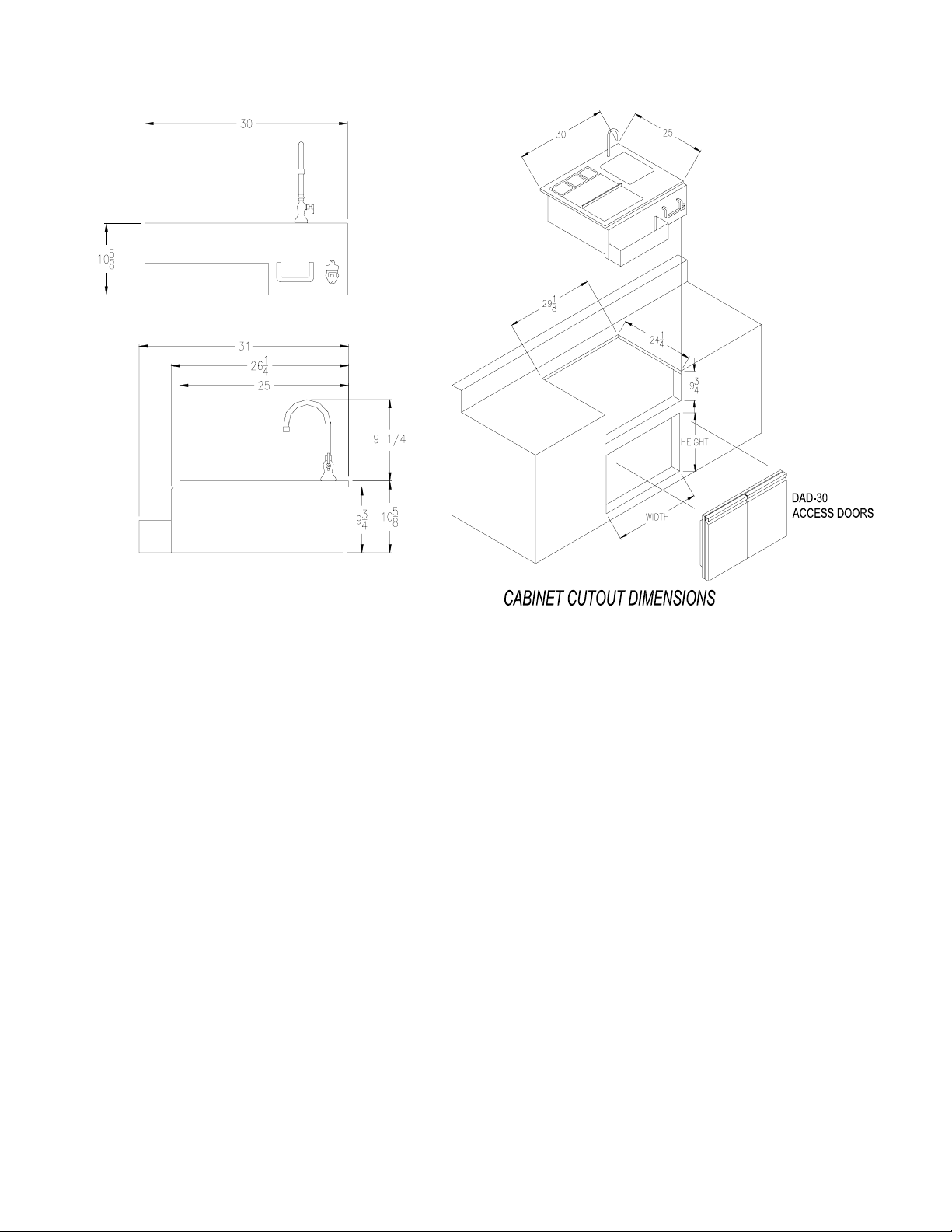
DBTA-30
DYNASTY 30” BUILT-IN BAR TENDER
C-5 16025981 © 2005 Maytag Services
Page 58
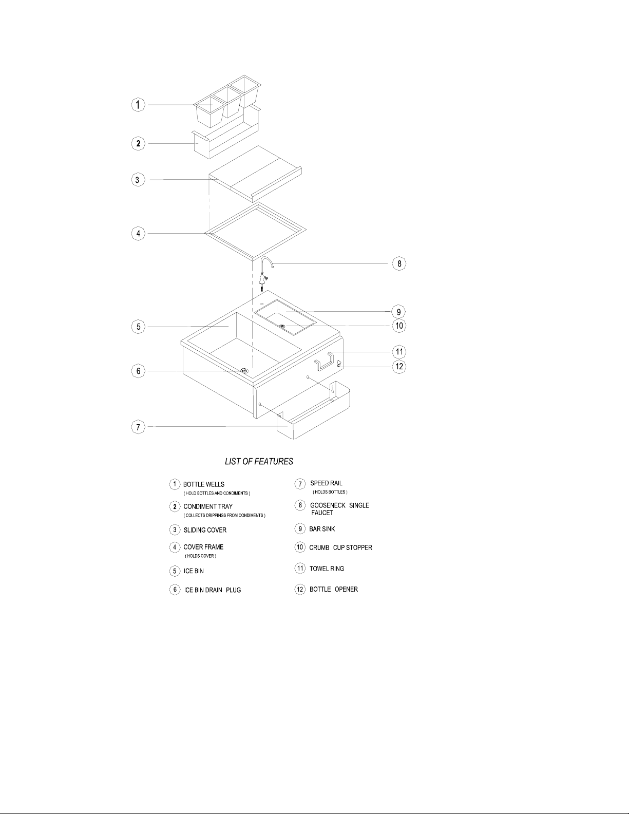
DBTA-30F
DYNASTY 30” FREESTANDING BAR TENDER
© 2005 Maytag Services 16025981 C-6
Page 59
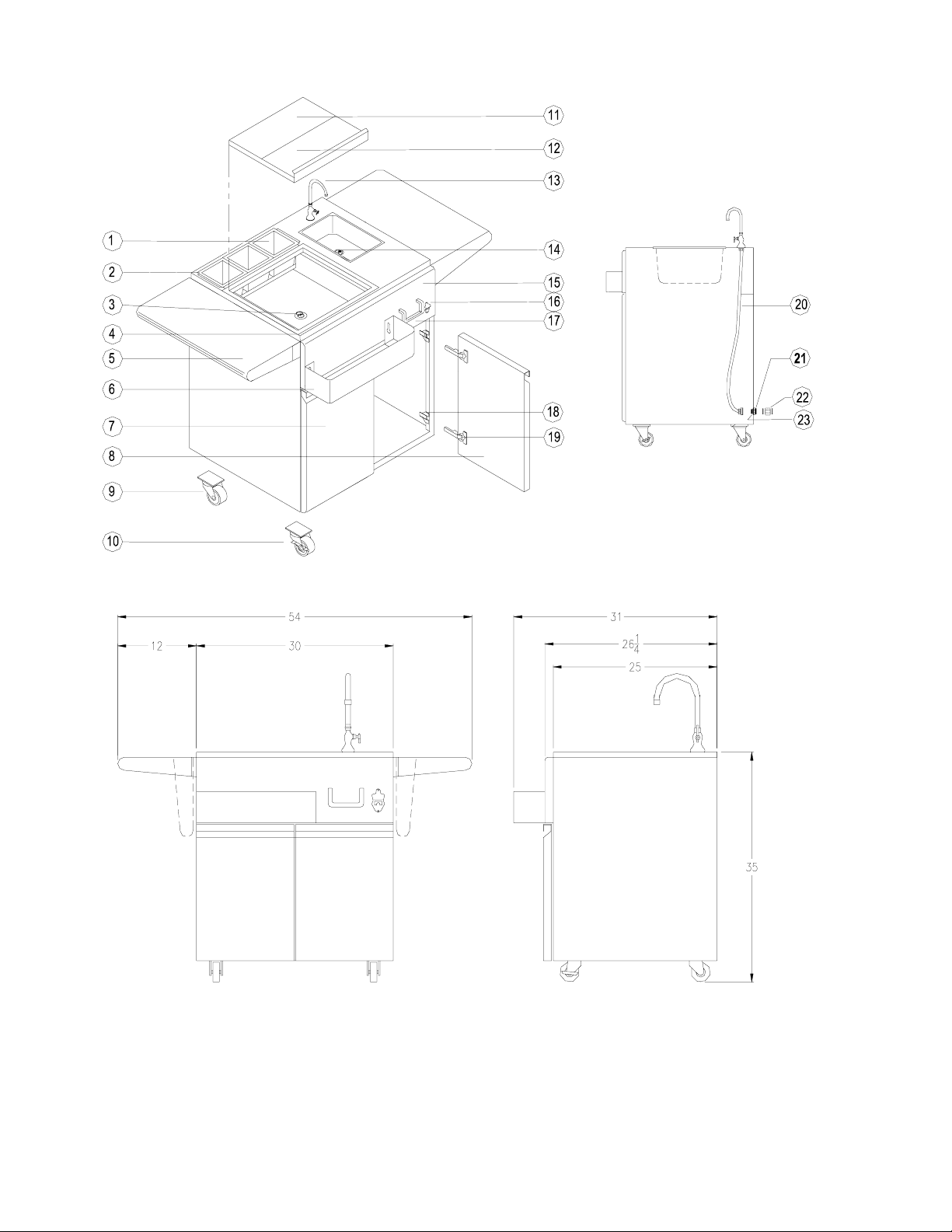
DYNASTY BAR TENDER
DRAIN KIT CONNECTION
C-7 16025981 © 2005 Maytag Services
Page 60
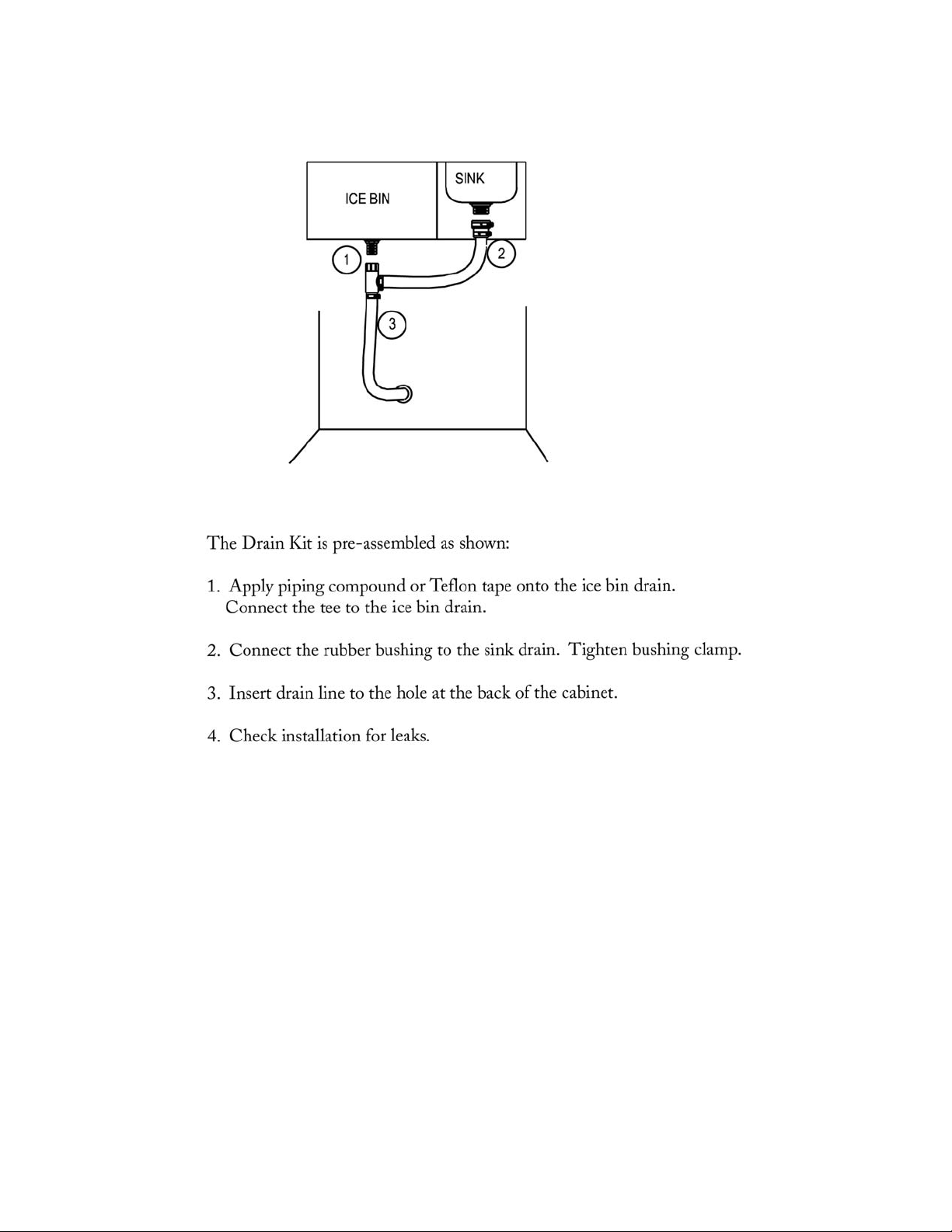
© 2005 Maytag Services 16025981 C-8
Page 61

CLEANING AND MAINTENANCE
The Dynasty Bar Tender is made of #304 stainless steel for long lasting beauty and service. It is nonrusting and non-magnetic.
Use stainless steel cleaner to clean the unit.
Mild soap and water can be used to wipe dirt.
Do not use steel wool to clean unit. Steel wool could leave metal fibers that will cause
rusting.
Do not use abrasives on the polished surfaces or they will loose their luster and
highlights. Use mild chrome cleaner, metal polish or WD40 to bring back luster.
To touch up minor scratches in the stainless steel surface, use a mild abrasive pad like
Scotch Brite or emery sand paper with 100 dry grit. Scrub the affected area very lightly
and always in the direction of the grain.
04/2003 P/N 18505
C-9 16025981 © 2005 Maytag Services
 Loading...