

Page 1
Series TFXM
MULTIPLE-PIPE, MULTIPLE-PATH CLAMP-ON ULTRASONIC
FLOW METER FOR LIQUIDS
Series TFXM Multiple-Pipe, Multiple-Path Transit
Time Flow Meters feature advanced non-invasive
flow measurement technology - providing a
measuring system with superior accuracy, versatility,
low cost of installation and low cost of ownership.
The TFXM system installs quickly onto liquid piping
systems with its non-invasive, non-fouling
transducers and can be configured and operational
within minutes. Mathematical formulas can be
applied to discrete flow measurements - up to eight
discrete channels/pipes - to display and output
average flow, flow difference, proportions or sums.
TFXM is designed for indoor and outdoor fixed
installations and is designed to operate on both AC
and DC power sources. The backlit graphics display
provides four lines of user-selected flow information
including rate, totalizer, liquid sound speed and signal
strength - for any meter connected to the TFXM
network. An integral optical interface is used with the
optional Windows
allows simple in-field programming, calibration and
software upgrades. All TFX systems utilize digital
signal processing, cross-correlation, and field
replaceable input/output modules.
®
ULTRALINKTM software utility and
A TFXM flow measurement system is a cost effective
versatile investment that can be readily configured for
piping from ½ inch (12 mm) and higher.
FEATURES BENEFITS
Multiple-path, single-pipe installations ensure accurate flow
measurements without the need for long runs of straight pipe.
User configurable rate and totalizer units include: feet, gallons, ft
million-gal, barrels (liquid & oil), acre-feet, lbs, meters, liters, m
3
3
,
million-liters and kg.
Each measurement channel contains integral 4-20 mA, dual-relay
and RS485 communications. Field replaceable output and
communication module options include: 200,000-event data logger,
rate pulse, and Heatflow/RTD.
Automatic Reynolds Number compensation ensures accurate
measurements through the laminar, transition and turbulent
system flow regions.
Ultralink software utility (free download) enables in-field flow
configuration, calibration and troubleshooting, via laptop PC.
,
Non-invasive clamp-on transducers are simple and cost efficient.
Since the transducers do not contact the liquid, fouling, pressure
drop, leaks and maintenance are eliminated.
Reduced installation time: no need to break into pipelines. Meter
can be configured and operational in minutes.
Reduced down-time: installation may be performed on full pipes.
No need to shut the process down for installation
or maintenance.
Low ownership costs: no repair kits, replacement parts, or
ongoing maintenance is necessary.
E
R
D
A
E
T
F
E
E
N
I
C
A
R
I
S
O
9
0
0
1
D
I
N
C
.
6
5
8
6
A
.
:
2
0
N
0
E
0
L
I
0
F
®
C US
®
www.dynasonics.com800.535.3569
Page 2
PRINCIPLES OF OPERATION
TFX transit time flow meters utilize two transducers, shown as elements A and B in Figure 1,
which function as both ultrasonic transmitters and receivers. The transducers are clamped
on the outside of a closed pipe at a specific distance from each other. (The transducers can
be mounted in V-mode as shown in Figure 1, W-mode where the sound transverses the pipe
four times, or in Z-mode where the transducers are mounted on opposite sides of the pipe.
This selection is based on pipe and liquid characteristics.) The flow meter operates by
alternately transmitting and receiving a frequency-modulated burst of sound energy between
the two transducers. The burst is first transmitted in the direction of fluid flow and then
against fluid flow. Since sound energy in a moving liquid is carried faster when it travels in the
direction of fluid flow (downstream) than it does when it travels against fluid flow (upstream),
a differential in the times of flight will occur. If the fluid is not moving, the time of flight
difference will be zero and the flow meter will indicate zero flow.
The sound’s time of flight is accurately measured in both directions and the difference in time
of flight is calculated. The liquid velocity (V) inside the pipe can be related to the difference in
time of flight (dt) through the following equation: V = K*D*dt, where K is a constant and D is
the distance between the transducers.
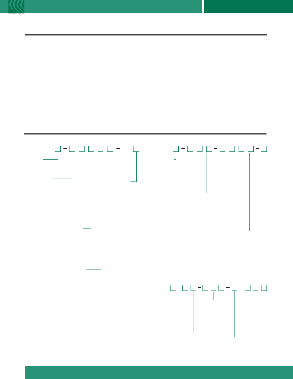
PART NUMBER CONSTRUCTION
Series TFXM Series TFXM
Top View
V-Mode Configuration Transit Time
Figure 1
TRANSMITTER-Wall mount bracket kit included
D T F X M D T TN
Channels
1) One Internal Channel
2) Two Internal Channels
Power Supply*
A) 115 VAC
B) 230 VAC
Channel 1 Input/Output
(RS485 is Standard on all Models)
1) 4-20 mA and Dual-Relay
2) Dual-Relay and One Option
3) 4-20 mA and One Option
Channel 1 Option Input/Output
N) None (If “1” is selected previously)
1) 4-20 mA (Secondary)
2) Dual Relay (Secondary)
3) Rate Pulse
6) Data Logger
7) Heatflow/RTD
Channel 2 Input/Output ( TFXM2)
N) None – ( TFXM1)
1) 4-20 mA and Dual Relay
2) Dual Relay and one Option
3) 4-20 mA and One option
Channel 2 Input/Output (TFXM2)
N) None – ( TFXM1 or if “1” is selected previously)
1) 4-20 mA (Secondary)
2) Dual Relay (Secondary)
3) Rate Pulse
6) Data Logger
7) Heatflow/RTD
*All TFXM units will also function in 10-28 VDC
Installation
N) General
Purpose
Options
N) None
2 ) 2 MHz DTTS/DTTC
transducers
TRANSDUCER-Pipes larger than 2" (50 mm)
Construction
N) Standard: +250 °F (+121 °C)
(CPVC, Ultem
H)
High Temp: +350 °F (+176 °C)
(PTFE, Vespel
Cable Length
020) 20 feet (6 m)
050) 50 feet (15 m)
100) 100 feet (30 m)
Maximum length: 990 feet (300 m)
in 10 ft. (3 m) increments
Conduit Length
(Standard construction: Conduit length = Cable length)
000) None
020) 20 feet (6 m)
050) 50 feet (15 m)
100) 100 feet (30 m)
Maximum length: 990 feet (300 m)
in 10 ft. (3 m) increments
Small Pipes – ½" to 2" (12 mm to 50 mm)
D T T
Type
S)
Standard: +185 °F (+85 °C)
(PVC, Ultem)
High Temp: +250 °F (+121 °C)
C)
(CPVC, Ultem)
Nominal
Pipe Size
D) ½"
F) ¾"
G) 1"
H) 1-¼"
J) 1-½"
L) 2"
®
)
®
)
Pipe Type
P) ANSI Pipe
C) Copper Pipe
T) Rigid Tubing
Conduit Type
N) None-RG59 Cable
A) Flexible Armored
Installation
N) General Purpose
F) CSA Class I, Div. 1,
Groups C & D
Cable Length
020) 20 feet (6 m)
050) 50 feet (15 m)
100) 100 feet (30 m)
Conduit Type
N) None - RG59 Cable
A) Flexible Armored
Conduit Length
000) None
020) 20 feet (6 m)
050) 50 feet (15 m)
100) 100 feet (30 m)
Page 3

S
PECIFICATIONS
T
RANSMITTER
DESCRIPTION SPECIFICATION
Power Requirements 10-28 VDC @ 8 VA maximum; 115/230 VAC 50/60 Hz ±15% @ 14 VA maximum
Velocity -40 to +40 FPS (-12 to +12 MPS)
Outputs All output modules are optically isolated from earth and system grounds
Standard (integrated) RS485 standard (Important: RS485 in the TFXM is dedicated to intra-TFX communications only. Connection of PCs
or other network devices to the TFXM network is not possible.)
Options (plug-in) 4-20 mA (secondary) 800 Ohms maximum; 12-bit resolution; passive or active
Dual Relay (secondary) Two separate Form C relays, 200 VAC maximum @ 0.5 A resistive
Rate Pulse FET output (open collector action), 0-2,500 Hz maximum, 1 A maximum
Data Logger 200,000-event, 16-bit, DB-9 connection, can be removed and installed without
disconnecting system power
Heatflow (see TFX Energy); Supports two 1000 RTDs, multiplexed, 12-bit resolution
Display 128
x
64 pixel graphics LCD, LED back lit. Two user selectable font sizes 0.35" (8.9 mm),
or 0.2" (5.0 mm); configure for either two or four data lines
Data Can be displayed for up to 8 pipes or paths: 8 digit rate, 8 digit totalizer, liquid sound speed, signal strength
Units
User configured - feet, gallons, ft3, mil-gal, barrels (liquid & oil), acre-feet, lbs., liters, meters, m3, Kg
Rate Rate time: sec, min, hr, day
Totalizer Forward, reverse, batch and net total
Ambient Conditions -40 to +185 °F (-40 to + 85 °C), 0-95% relative humidity, non-condensing
x
Enclosure NEMA 4 (IP-66) epoxy-coated steel, polycarbonate keypad and SS hardware. 11.0H
(280H
Accuracy Flow Rate DTTN/DTTH ±
x
290W x 106D mm); 11.5 lbs. (5.2 Kg)
1% of reading at rates > 1 FPS (0.3 MPS), ±0.01 FPS (±0.003 MPS) at rates lower than FPS;
11.4W x 4.2D inches
DTTS/DTTC 1" and larger units ±1% of reading from 10-100% of measuring range, ±0.01 FPS (±0.003 MPS at rates
lower than 10% of measuring range; ½" and ¾" units ±1% FS. Refer to the Dimensional Specifications page for
applicable measuring ranges for each DTTS/DTTN transducer model.
Sensitivity Flow: 0.001 FPS (0.0003 MPS)
Repeatability ±0.5% of reading
Response Time Flow: 0.3-300 seconds, user configured, to 100% of value, step change in flow
Security Keypad lockout, user selected four digit access code
ULTRALINK
TM
Utility
IBM compatible, Windows® 98/2000/XP/Vista® operating system
TRANSDUCER
DESCRIPTION SPECIFICATION
Liquid Types Supported Virtually all non-aerated liquids
Transducer to (Std.) 20, 50, 100 feet (6, 15, 30 meters); (Opt.) lengths to 990 feet (300 meters)
Transmitter Distance RG59 - 75 OHM Coaxial cable
Pipe Sizes DTTN/DTTH: Larger than 2 inch (50 mm)
DTTS/DTTC: ½ inch to 2 inch (12 mm to 50 mm)
DTTN/DTTC: -40 to +250 °F (-40 to +121 °C); DTTH: -40 to +350 °F (-40 to +176 °C)
Pipe Surface
Temperature
DTTS: -40 to +185 °F (-40 to +85 °C)
Environment DTTN/DTTH: NEMA 6P (IP-68) DTTS/DTTC: NEMA 4X (IP-66); .0-95% relative humidity, non-condensing
Housing Material DTTN/DTTC: CPVC, Ultem
DTTS: PVC, Ultem
®
and Nylon
Installation
General purpose
®
and Nylon; DTTH: PTFE, Vespel
DTTN Transducer and IS Barrier (-F option)DTTN Transducer (-N option)
Hazardous Location Designation: Class I Div 1,
Groups C & D; T5 Intrinsically Safe Exia
Process Control Equipment: CSA C22.2 No. 142
Intrinsically Safe Equipment: CSA C22.2 No. 157
Intrinsically Safe & Associated Apparatus: UL 913
Energy Management Equipment: UL 916
®
and Nickel-Plated Brass;
C US
®
Page 4

ISO-MOD INPUT/
General
The standard TFXM provides integral RS485 communications in
addition to two relays per measurement channel and one 4-20 mA
output per measurement channel. TFXM permits the selection of
one other input/output device, selected from the list below, per
measurement channel. If an optional input/output device is
required, either the 4-20 mA or the dual-relay device must be
disabled for that particular measurement channel. All output
electronics and modules are 2,500 V optically isolated from TFXM
power and Earth grounds – eliminating the potential for ground
loops and reducing the chance of severe damage in the event of
an electrical surge.
Five ISO-MOD options are available for TFXM including: 4-20 mA
(secondary), dual-relay (secondary), rate pulse, 200,000-event
data logger, and Heatflow/RTD. All modules are field configurable
by utilizing the keypad or ULTRALINK
various ISO-MODs are described below. See the TFX Energy
datasheet for details regarding the Heatflow/RTD module option.
4-20 mA Output Module
Easily configured via switch selections into either an internally
powered or externally powered mode, the 4-20 mA Output
Module interfaces with virtually all recording and logging systems
by transmitting an analog current signal that is proportional to
system flow energy rate. Independent 4 mA and 20 mA span
settings are established in software. These settings can span
negative and positive flow directions to output bi-directional flow
data. Output resolution of the module is 12-bits (4,096 discrete
points) and because of its low insertion loss characteristics (less
than 5 V typical) the module can drive more than 800 ohms of
load with a 24 V power source.
Dual Relay Module
Two independent SPDT (single-pole, double-throw, Form C) relays
are contained in this module. The relay operations are userconfigured via software to act in either a flow rate alarm, signal
strength alarm, water meter pulser or totalizer/batching mode. The
relays are rated for 200 VAC max. and have a current rating of
0.5 A resistive load (175 VDC @ 0.25 A resistive). It is highly
recommended that a secondary relay be utilized whenever the
Control Relay ISO-MOD is used to control inductive loads such
as solenoids and motors.
O
UTPUT MODULES
TM
interface. Features of the
Rate Pulse Output Module
The Rate Pulse Output Module is utilized to transmit information to
external counters and PID systems via a frequency output that is
proportional to system flow energy rate. Independent Zero and
Span settings are established in software using the Flow Measuring
Range entries. These settings can span negative and positive flow
directions to output bi-directional flow data. Output resolution of
the module is 12-bits (4,096 discrete points) and the maximum
output frequency setting is 2,500 Hz – other frequency ranges may
be available, please consult the Dynasonics factory. The module
has a MOSFET output with an “On” resistance of 0.21 ohms and is
rated at 100 V, 1 A continuous operation.
Data Logger Module
This powerful 200,000-event data logger/electronic stripchart
recorder can be configured to match user applications. The logger
stores time-stamped, high resolution (16-bit) data at user-selected
intervals ranging from 1 to 1,000 seconds.
A computer can be connected to the DB9 connector without
removing the logger from the flow meter. Data can be extracted
via the supplied Windows® compatible software utility.
ULTRALINK
Real-Time Infrared Communications. Configuration and
calibration are quick and simple using ULTRALINK
PC. Dynasonics Infrared Serial Adapter (P.N. D005-2115-001)
allows full programming access without the need to open the
TFXM enclosure or connect wires.
TM
SOFTWARE
U
TILITY
™
and your
Designed with the user/operator in mind, configuration and
calibration of transit time ultrasonic flow meters have never been as
simple and straight-forward as with Series TFXM. Integration of your
PC, the TFXM flow meter and ULTRALINK™ provide the ultimate in
operator control. ULTRALINK™ is a software utility that operates on
a Windows® PC operating system and communicates with TFXM
flow meters through a serial communications port and infrared serial
adapter (P.N.D005-2115-001). Since the communication link is
infrared light, the user need only be within 10 feet (3 meters) of the
TFXM meter – interconnection wires are not necessary.
™
Note: Series TFXM does not require ULTRALINK
computer for configuration. However, the software and a computer
are requirements for in-field calibration and some advanced
functions of TFXM systems.
or the use of a
Page 5

PRODUCT
I
NSTALLATION DIMENSIONAL
C
B
A
Multiple-Pipe Master Flow Meter
Multiple pipes can be configured and displayed on
the TFXM console.
Multiple-Pipe Summation Flow Meter
Displays the actual flow of multiple pipes as well as the
sum of multiple flow rates.
Hazardous (Classified) Location
Class I, Division 1 Groups C and D
Maximum Ambient Temperature: -40º to +85 ºC
Multiple-Pipe Difference Flow Meter
Displays the actual flow of pipes and the difference flow of
a non-measured pipe.
Multiple-Path Single-Pipe Flow Meter
By averaging multiple paths on a single pipe, stability and accuracy
of measurements can be improved.
Non-Hazardous Location
Maximum Ambient Temperature: -40 ºC to +50 ºC
Sensing surface:
Couple to pipe with
RTV or silicone grease
supplied, per installation
manual.
BLACK
RED
RED
BLACK
Connect to Dynasonics
Transmitter
INTRINSIC SAFETY BARRIER
Intrinsically safe connections Class I, Groups C and D;
Class II, Groups E, F, G;
Class III, Hazardous locations [ Exia ]
“Associated Equipment” Appareillage Connexe”
Maximum Safe Area Voltage: 250 V
Maximum Voltage: 20V, Maximum Current: 150mA
Control Drawing No. D091-1053-005
WARNING: Substitution of components may impair intrinsic safety.
A VERTISSEMENT: La substitution de composants peut compromettre la Securite Intrinseque.
MANUFACTURED DATE:
11/04
ULTRASONICS
MODEL: 070-1010-002
Division of Racine Federated, Inc.
Racine, WI U.S.A.
Tel: 262-639-6770 Fax: 262-639-2267
www.dynasonics.com
®
c
US
Page 6

S
PECIFICATIONS
Series TFXMSeries TFXM
MECHANICAL DIMENSIONS: INCHES (MM) DTTS/DTTC TRANSDUCER DIMENSIONS: INCHES (MM)
Pipe
Pipe
Material
Size
½"
¾"
1"
1-¼"
1-½"
2"
* Varies due to U-bolt configuration
2.375
(60.3)*
2.125
(54.0)*
Measuring
Range
2 - 38 GPM
8 - 144 LPM
1.8 - 27 GPM
7 - 102 LPM
1.5 - 18 GPM
6 - 68 LPM
2.75 - 66 GPM
10 - 250 LPM
2.5 - 54 GPM
10 - 204 LPM
2.5 - 45 GPM
10 - 170 LPM
3.5 - 108 GPM
13 - 409 LPM
3.5 - 95 GPM
13 - 360 LPM
3.5 - 85 GPM
13 - 320 LPM
5 - 186 GPM
19 - 704 LPM
4.5 - 152 GPM
17 - 575 LPM
4 - 136 GPM
15 - 514 GPM
6 - 250 GPM
23 - 946 LPM
5 - 215 GPM
19 - 814 LPM
5 - 200 GPM
19 - 757 LPM
8 - 420 GPM
30 - 1590 LPM
8 - 375 GPM
30 - 1419 LPM
8 - 365 GPM
30 - 1381 LPM
10" (250 mm) Scaled Mounting Track
[Optional 16" (405 mm) track
also available]
19.20
(489.0)
DYNASONICS is a registered trademark of Racine Federated Inc.
Ultralink is a trademark of Racine Federated Inc.
ULTEM is a registered trademark of General Electric Co.
VESPEL is a registered trademark of E.I. duPont de Nemours and Company
WINDOWS and Vista are registered trademarks of Microsoft Corp.
©2008 Racine Federated Inc., all rights reserved
FORM TFXD 6/08
Racine Flow Meter Group
DTTN/DTTH
Pipes larger than 2" (50 mm)
3.00 (76.2)
MIN Clearance
2.75
(69.8)
2.95
(74.9)
DTTS/DTTC
Pipes ½" to 2"
(12 mm to 50 mm)
B
D
C
8635 Washington Ave. Racine, WI 53406-3738 USA
Tel:
262.639.6770
Fax: 262.639.2267
www.dynasonics.com dynasonics_sales@racinefed.com
DTTS/DTTC U-Bolt Connections
[ANSI & Copper 2" (50 mm) Models]
D
A
800.535.3569 US & Canada
800.732.8354 US & Canada
C
®
B
 Loading...