

Page 1
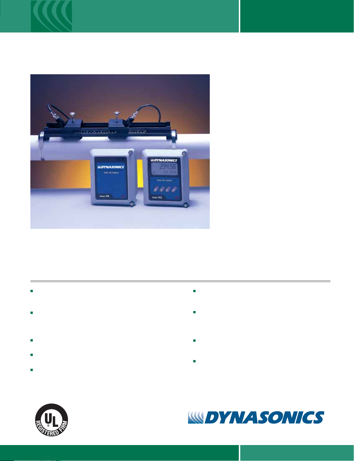
FIXED LOCATION TRANSIT TIME FLOW METER
Series TFXD Transit Time Flow Meters feature
the world’s most advanced non-invasive flow
measurement technology available – providing
a measuring system with superior accuracy,
versatility, low cost of installation and low cost
of ownership. The TFXD system installs quickly
onto liquid piping systems with its non-invasive,
non-fouling transducers and can be configured
and operational within minutes.
The TFXD is designed for fixed-location
installation on liquid systems and is available in
both blind (TFXD1) and display (TFXD2) models.
The TFXD2 has a large LCD and an integral
keypad that allows field configuration without the
use of a computer.
optical interface
ULTRALINK
allows simple in-field programming, calibration
and software upgrades. All systems utilize digital
signal processing, cross-correlation and field
replaceable
which can be used with the
™
software utility. The software utility
input/output
Series TFXD
The TFXD also provides an
modules.
* Optional aluminum track assembly shown.
FEATURES
Non-invasive, NEMA 6P (IP-68) clamp-on transducers are
cost-effective and simple to install. Since the transducers do not
contact the liquid, fouling and maintenance are eliminated.
TFXD has a flow measuring range that is much larger than other
flow meter technologies. This feature allows the instrument to
measure normal process flow rates as well as flows resulting
from leaks in piping and valves.
Inherent flow profile compensation permits increased
accuracy over alternate technologies.
Bi-directional measurements, with totalization in positive,
negative, net or batch modes.
Zero head-loss results in improved pumping efficiency.
The TFXD flow measurement system is a
cost-effective, versatile investment that can be
readily configured for piping ½" (12 mm)
and higher.
Low power consumption. The TFXD system operates on less
than 2.5W, allowing operation on UPS, solar panel and battery
operated power sources.
An integral optical interface and optional Windows
®
software
utility provide complete control of system configuration,
calibration and diagnostics – without opening the NEMA 4X
(IP-66) enclosure.
Field-replaceable I/O module options include: 4-20 mA, dual
relay, rate pulse, RS232C, RS485, 200K-event data logger, and
Heatflow/RTD.
User configurable rate and totalizer units include: feet, gallons,
3
ft
, million-gal, barrels, acre-feet, lbs, meters, liters, m3,
million-liters and kg.
E
R
D
A
E
T
F
E
N
I
C
A
R
I
S
O
9
0
0
1
:
2
E
D
I
N
C
.
6
5
8
6
A
.
0
N
0
E
0
L
I
0
F
TM
www.dynasonics.com800.535.3569
Page 2
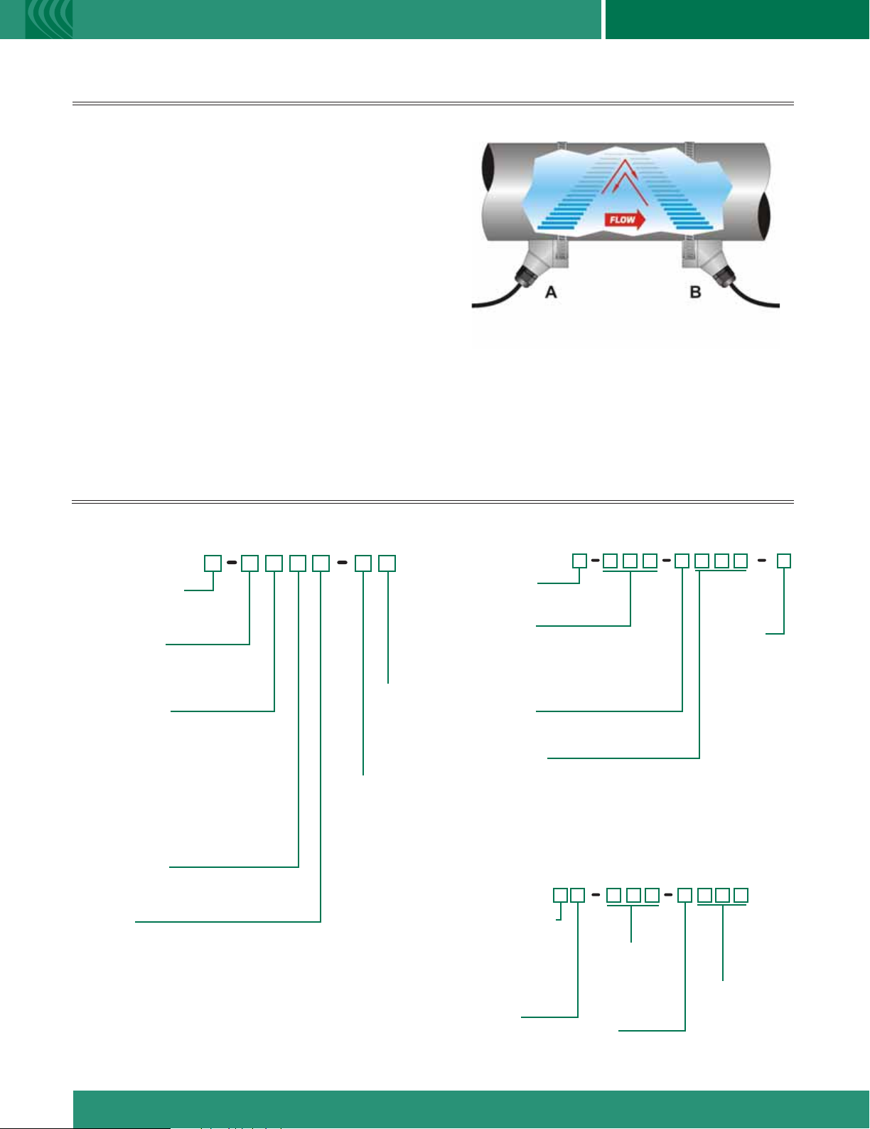
PRINCIPLES OF OPERATION
Series TFXD Series TFXD Series TFXD
FIXED LOCATION TRANSIT
TIME FLOW METER
TFXD transit time flow meters utilize two transducers,
shown as elements A and B in Figure 1, which function
as both ultrasonic transmitters and receivers. The
transducers are clamped on the outside of a closed
pipe at a specific distance from each other. (The
transducers can be mounted in V-mode as shown in
Figure 1, W-mode where sound transverses the pipe
four times, or in Z-mode where the transducers are
mounted on opposite sides of the pipe. This selection
is based on pipe and liquid characteristics.) The flow
meter operates by alternately transmitting and receiving
a frequency modulated burst of sound energy between
the two transducers. The burst is first transmitted in the
direction of fluid flow and then against fluid flow. Since
sound energy in a moving liquid is carried faster when it
travels in the direction of fluid flow (downstream) than it
does when it travels against fluid flow (upstream), a
differential in the times of flight will occur. If the fluid is
not moving, the time of flight difference will be zero and
PART NUMBER CONSTRUCTION
TRANSMITTER – Wall mount bracket kit included
Figure 1 Top View
Reflect-Mode Configuration
Transit Time
the flow meter will indicate zero flow. The sound’s time of
flight is accurately measured in both directions and the
difference in time of flight is calculated. The liquid velocity (V)
inside the pipe can be related to the difference in time of
flight (dt) through the following equation:
V = K*D*dt
where K is a constant and D is the distance between
the transducers.
TRANSDUCER – Pipes larger than 2" (50 mm)
D T F X D
Transmitter Type
1) Blind
2) Rate and Totalizer Display
Power Supply
A) 115 VAC
B) 230 VAC
E) 10-28 VDC
Input/Output 1
N) None
1) 4-20 mA
2) Dual Relay
3) Rate Pulse
4) RS232C
5) RS485
6) Data Logger
7) Heatflow/RTD
Input/Output 2
Same as Selecting Input/Output 1
Totalizer
N) (Std on DTFXD1) None
A) (Std on DTFXD2) Eight Digit Resettable
Options
N) None
2)
2 MHz
DTTS
transducer
Installation
N) General Purpose
D T T
Construction
N) Standard (CPVC, Ultem®)
H) High Temp (PTFE, Vespel
Cable Length
020) 20 feet (6 m)
050) 50 feet (15 m)
100) 100 feet (30 m)
Maximum length: 990 feet (300 m)
in 10 ft. (3 m) increments
Conduit Type
N) None - RG59 Cable
A) Flexible Armored
Conduit Length
(Standard Construction: Conduit Length = Cable Length)
000) None
020) 20 feet (6 m)
050) 50 feet (15 m)
100) 100 feet (30 m)
Maximum length: 990 feet (300 m) in 10 ft. (3 m) increments
®
)
Installation
N)
General Purpose
F) CSA Class I Div. 1,
Groups C & D
Small Pipes – ½" to 2" (12 mm to 50 mm)
D T T S
Nominal Pipe Size
D) ½ inch
F) ¾ inch
G) 1 inch
H) 1-¼ inch
J) 1-½ inch
L) 2 inch
Pipe Type
P) ANSI Pipe
C) Copper Pipe
T) Tubing
Conduit Type
N) None - RG59 Cable
A) Flexible Armored
Cable Length
020) 20 feet (6 m)
050) 50 feet (15 m)
100) 100 feet (30 m)
Conduit Length
000) None
020) 20 feet (6 m)
050) 50 feet (15 m)
100) 100 feet (30 m)
Page 3

S
PECIFICATIONS
T
RANSMITTER
DESCRIPTION SPECIFICATION
Power Requirements (Std.) 10-28 VDC @ 2.5 VA max.; 115/230 VAC 50/60 Hz ±15% @ 5 VA max.
Velocity -40 to +40 FPS (-12 to +12 MPS)
Inputs/Outputs All modules are optically isolated from earth and system grounds; maximum of two modules may be installed
Optional 4-20 mA 800 Ohms max.; 12-bit resolution; passive or active
Dual Relay Two separate Form C relays, 200 VAC max. @ 0.5 A resistive
Rate Pulse FET output (open collector action), 0-2,500 Hz maximum, 1 A maximum
RS232C data rate to 57.6K
RS485 supports up to 126 drops
Data Logger
Display [TFXD2 only] 2 line x 8 character LCD, back lit. Top row: 7-segment digit height 0.7 inches (18 mm),
Bottom row: 14-segment digit height 0.35 inches (9 mm); 8 digit rate, 8 digit totalizer (resettable)
Units
Rate Rate time: sec, min, hr, day
Totalizer Forward, reverse, batch and net total
Ambient Conditions -40 °F to +185 °F (-40 °C to +85 °C), 0-95% relative humidity, non-condensing
Enclosure NEMA 4X (IP-66), polycarbonate, SS, brass and plated steel. 7.00H x 5.75W x 3.88D inches (178H x 146W x 99D mm)
Accuracy Flow Rate ±0.5% of reading at rates > 1 FPS (0.3 MPS) for field calibrated systems; ±1% of reading at rates > 1 FPS (0.3 MPS)
uncalibrated; 0.1 FPS (0.03 MPS) at rates < 1 FPS (0.3 MPS)
Sensitivity Flow: 0.001 FPS (0.0003 MPS)
Repeatability ±0.01% of reading
Response Time Flow: 0.3-30 seconds, user configured, to 100% of value, step change in flow
Security Keypad lockout, user selected four digit access code
™
ULTRALINK
Utility IBM compatible, Windows® 95/98/2000/XP operating system
Heatflow (see TFX BTU-Pro data sheet); Supports two 1000 RTDs, multiplexed, 12-bit resolution
User configured - feet, gallons, ft3, Mil-gal, barrels, acre-feet, lbs., meters, liters, m3, Mil-liters, Kg
200,000 event, 16-bit, DB-9 connection, can be removed and installed without disconnecting system power
T
RANSDUCER
DESCRIPTION SPECIFICATION
Liquid Types Supported Virtually all non-aerated liquids
Transducer to (Std.) 20, 50, 100 feet (6, 15, 30 meters); (Opt.) lengths to 990 feet (300 meters)
Transmitter Distance RG59 - 75 OHM Coaxial cable
Pipe Sizes DTTN/DTTH: Larger than 2 inch
DTTS: ½ inch to 2 inch (12 mm to 50 mm)
Environment DTTN/DTTH: NEMA 6P (IP-68)
DTTS: NEMA 4X (IP-66)
Pipe Surface Temperature
DTTS: -40 °F to +185 °F (-40 °C to +85 °C)
Ambient Temperature
Housing Material DTTN: CPVC, Ultem® and Nylon; DTTH: PTFE, Vespel®, Nickel-Plated Brass
DTTS: PVC, Ultem
Mounting (Std.) Stainless strap P.N. D002-2007-001; (Opt.) Aluminum track assemblies w/graduated scales
Installation (Std.) General purpose; (Opt.) CSA Class I Division 1, Groups C and D (includes intrinsic safety barrier)
DTTN: -40 °F to +250 °F (-40 °C to +121 °C); DTTH: -40 °F to +350 °F (-40 °C to +176 °C)
-40 °F to +185 °F (-40 °C to +85 °C), 0-95% relative humidity, non-condensing
®
and Nylon
Page 4

ISO-MOD INPUT/OUTPUT
Field-Replaceable Electronic Modules
for System Integration
General
ISO-MODs are epoxy-encapsulated electronic
modules that are simple to install and replace in the field.
All modules are 2,500 V optically isolated from TFXD
power and Earth grounds – eliminating the potential for
ground loops and reducing the chance of severe damage
in the event of an electrical surge.
Seven ISO-MOD options are available including:
4-20 mA, dual relay, rate pulse, RS232C, RS485, 200K
event data logger and Heatflow/RTD (see TFX BTU-Pro
data sheet). TFXD supports any two ISO-MOD
modules. All modules are field-configurable by utilizing the
keyboard or ULTRALINK™ interface. Field wiring
connections to ISO-MODs are quick and easy using
pluggable terminals. Features of the various ISO-MODs are
described below.
4-20 mA Output Module
Easily configured via jumper selections into either an
internally powered or externally powered mode, the 4-20
mA Output Module interfaces with virtually all recording
and logging systems by transmitting an analog current
signal that is proportional to system flow energy rate.
Independent 4 mA and 20 mA span settings are
established in software. These settings can span negative
and positive flow directions to output bi-directional flow
data. Output resolution of the module is 12-bits (4,096
discrete points) and because of its low insertion loss
characteristics (less than 5 V typical) the module can drive
more than 800 Ohms of load with a 24 V power source.
Dual Relay Module
Two independent SPDT (single-pole, double-throw, Form
C) relays are contained in this module. The relay
operations are user-configured via software to act in either
a flow rate alarm, signal strength alarm, water meter pulser
or totalizer/batching mode. The relays are rated for 200
VAC max. and have a current rating of 0.5 A resistive load
(175 VDC @ 0.25 A resistive). It is highly recommended
that a secondary relay be utilized whenever the Control
Relay ISO-MOD is used to control inductive loads such as
solenoids and motors.
Rate Pulse Output Module
The Rate Pulse Output Module is utilized to transmit
information to external counters and PID systems via a
frequency output that is proportional to system flow energy
rate. Independent Zero and Span settings are established
in software using the Flow Measuring Range entries.
settings can span negative and positive flow directions to
output bi-directional flow data. Output resolution of the
module is 12-bits (4,096 discrete points) and the
maximum output frequency setting is 2,500 Hz – other
frequency ranges may be available, please consult the
Dynasonics factory. The module has a MOSFET output
with an “On” resistance of 0.21 Ohms and is rated at
100 V, 1 A continuous operation.
M
ODULES
input/output
input/output
These
RS232C Input/Output Module
The RS232 Module can be interfaced with the serial
communication ports of PCs, PLCs and SCADA systems
that are used to monitor flow rate information in piping
systems. The RS232 Module may also be used to form a
hardwire connection to a PC that is running the
ULTRALINK™ software utility. Baud rates up to 57.6K
are supported.
RS485 Input/Output Module
The RS485 Module allows up to 126 TFX systems to be
placed on a single three-wire cable bus. All meters are
assigned a unique serial number that allows all of the
meters on the cable network to be independently
accessed. Baud rates up to 57.6K and cable lengths to
990 feet (300 meters) are supported.
Data Logger Module
This powerful 200,000-event data logger/electronic
stripchart recorder is available as an option in the TFXD
system and can be configured to match user applications.
The logger stores time-stamped, high resolution (16-bit)
data at user-selected intervals ranging from 1 to 1,000
seconds. Configuration of and data retrieval from the
logger can be accomplished in two ways:
The module can be removed and carried in a shirt
pocket back to the office and plugged into a PC serial
port via the module’s integral DB9 connector. This
eliminates the requirement to carry a laptop computer to
the flow meter site.
A computer can be connected to the DB9 connector
without removing the logger from the flow meter. Data
can be extracted via the supplied Windows
software utility.
®
Page 5

Windows®-based Software Utility. A complete meter configuration,
calibration and troubleshooting tool.
Provides quick access to all configuration parameters with
pop-up windows and pull-down menus.
Assists in selection of proper position and mounting locations
of transducers.
Selection of units of measure and measuring range.
Contains a powerful in-field multi-point calibration routine.
Displays error codes and logs reset functions.
Stores meter configurations to a file that can be archived or
used to configure additional meters.
Designed with the user/operator in mind,
configuration and calibration of ultrasonic flow
meters have never been as simple and straight
forward as with Series TFXD. Integration of your
PC, the TFXD flow meter and ULTRALINK
™
provides the ultimate in operator control.
ULTRALINK
™
is a Windows® 95/98/2000/XP
software utility that communicates with TFXD
flow meters through a PC serial communications
port and infrared serial adapter (Dynasonics
P.N. D005-2115-001 shown below). Since the
communication link is infrared light, the user need
only be within 10 feet (3 meters) of the TFXD
meter – interconnection wires are not necessary.
Note: Model TFXD2 (with integral keypad and
display) does not require ULTRALINK
™
or the
use of a computer for configuration. Model
TFXD1 (without keypad and display) does
require the software and computer for system
configuration. The software and computer are
requirements for in-field calibration of TFXD
systems and to access advanced features of
the TFXD system.
User-Friendly Operations. Configuration of the TFXD
is provided through a simple menu structure. Selections
for units of measure, measuring range, input/output
options and configurations storage are available.
Real-Time Infrared Communications. Configuration
and calibration are quick and simple using ULTRALINK
™
and your PC. Dynasonics Infrared Serial Adapter
(P.N. D005-2115-001) allows full programming access.
Infrared Serial Adapter. Dynasonics P.N. D005-2115-001
transmits and receives data from TFXD flow meters from
up to 10 feet (3 meters) away. Simply point the front of the
adapter at the TFXD and start ULTRALINK
™
on your PC.
Page 6

DIMENSIONAL
S
PECIFICATIONS
MECHANICAL DIMENSIONS: INCHES (mm)
TFXD2 Transmitter Shown
4.19 (106.4)
3.88 (98.5)
7.00
(177.8)
5.75
(146.1)
Pipe
Size
½"
¾"
Pipe
Material
Series TFXDSeries TFXD
Measuring
Range
(3) 1/2" Conduit Holes
Wall Mount
.35 (8.9)
6.08 (154.4)
6.74 (171.2)
Intrinsic Safety Barrier
(Included with CSA
Class I Div. I,
Groups C and
D transducers)
10" (250 mm) Scaled Mounting Track
[Optional 16" (405 mm) track
also available]
19.20
(489.0)
Power
Connection
Transducer
Connection
2.13 (54.1)
3.31
(79.5)
1.55 (39.4)
.28 (7.1) DIA
(4 Places)
DTTN
Pipe larger than 2"
3.00 (76.2)
MIN Clearance
2.75
(69.8)
Input
Output
2.95
(74.9)
1"
1-¼"
1-½"
2"
* Varies due to U-bolt configuration
DTTS
Pipe ½" to 2"
(12 mm to 50 mm)
B
D
DTTS U-Bolt Connections
[ANSI & Copper 2" (50 mm) Models]
D
2.375
(60.3)*
2.125
(54.0)*
B
Dynasonics and ULTRALINK are trademarks of Racine Federated Inc.
ULTEM is a registered trademark of General Electric Co.
VESPEL is a registered trademark of E.I. duPont de Nemours and Company
WINDOWS is a registered trademark of Microsoft Corp.
CSA is a registered trademark of Canadian Standards Association
FORM TFXD 9/07
Racine Flow Meter Group
C
8635 Washington Ave. Racine, WI 53406-3738 USA
Tel:
262.639.6770
Fax: 262.639.2267
www.dynasonics.com dynasonics_sales@racinefed.com
A
800.535.3569 US & Canada
800.732.8354 US & Canada
C
TM
 Loading...