

Page 1
Transit Time Ultrasonic Flow Meters
TFX-500w Clamp-On Meter
TTM-UM-02537-EN-04 (April 2019)
User Manual
Page 2

Transit Time Ultrasonic Flow Meters, TFX-500w Clamp-On Meter
Page ii April 2019TTM-UM-02537-EN-04
Page 3

User Manual
CONTENTS
Scope of This Manual . . . . . . . . . . . . . . . . . . . . . . . . . . . . . . . . . . . . . . . . . . . . . . . . . . . . . . . . . . . . . . . . . . . . 5
Typographic Conventions . . . . . . . . . . . . . . . . . . . . . . . . . . . . . . . . . . . . . . . . . . . . . . . . . . . . . . . . . . . . . .5
Unpacking and Inspection . . . . . . . . . . . . . . . . . . . . . . . . . . . . . . . . . . . . . . . . . . . . . . . . . . . . . . . . . . . . . . . . 5
Safety . . . . . . . . . . . . . . . . . . . . . . . . . . . . . . . . . . . . . . . . . . . . . . . . . . . . . . . . . . . . . . . . . . . . . . . . . . . . . .5
Terminology and Symbols . . . . . . . . . . . . . . . . . . . . . . . . . . . . . . . . . . . . . . . . . . . . . . . . . . . . . . . . . . . . . . 5
Considerations . . . . . . . . . . . . . . . . . . . . . . . . . . . . . . . . . . . . . . . . . . . . . . . . . . . . . . . . . . . . . . . . . . . . .5
Introduction. . . . . . . . . . . . . . . . . . . . . . . . . . . . . . . . . . . . . . . . . . . . . . . . . . . . . . . . . . . . . . . . . . . . . . . . . .6
Dimensions . . . . . . . . . . . . . . . . . . . . . . . . . . . . . . . . . . . . . . . . . . . . . . . . . . . . . . . . . . . . . . . . . . . . . . . . . . 6
Operation . . . . . . . . . . . . . . . . . . . . . . . . . . . . . . . . . . . . . . . . . . . . . . . . . . . . . . . . . . . . . . . . . . . . . . . . . . .7
Keypad Operation on the Home Screen . . . . . . . . . . . . . . . . . . . . . . . . . . . . . . . . . . . . . . . . . . . . . . . . . . . . . 7
Keypad Operation in the Menu Structure . . . . . . . . . . . . . . . . . . . . . . . . . . . . . . . . . . . . . . . . . . . . . . . . . . . . 7
Selecting an Option in a Parameter Selection List . . . . . . . . . . . . . . . . . . . . . . . . . . . . . . . . . . . . . . . . . . . . . . . 8
Entering a Number . . . . . . . . . . . . . . . . . . . . . . . . . . . . . . . . . . . . . . . . . . . . . . . . . . . . . . . . . . . . . . . . . .8
Installation. . . . . . . . . . . . . . . . . . . . . . . . . . . . . . . . . . . . . . . . . . . . . . . . . . . . . . . . . . . . . . . . . . . . . . . . . . .9
Overview . . . . . . . . . . . . . . . . . . . . . . . . . . . . . . . . . . . . . . . . . . . . . . . . . . . . . . . . . . . . . . . . . . . . . . . . .9
Installation Considerations . . . . . . . . . . . . . . . . . . . . . . . . . . . . . . . . . . . . . . . . . . . . . . . . . . . . . . . . . . . . .9
Equipment Required . . . . . . . . . . . . . . . . . . . . . . . . . . . . . . . . . . . . . . . . . . . . . . . . . . . . . . . . . . . . . . . . .9
Installing the Transducers . . . . . . . . . . . . . . . . . . . . . . . . . . . . . . . . . . . . . . . . . . . . . . . . . . . . . . . . . . . . . . 9
Installing a Meter with a Remote Transmitter and Fixed Transducers . . . . . . . . . . . . . . . . . . . . . . . . . . . . . . . . . . 10
Installing a Meter with a Remote Transmitter and Adjustable Transducers . . . . . . . . . . . . . . . . . . . . . . . . . . . . . . 11
Installing a Meter with an Integral Transmitter . . . . . . . . . . . . . . . . . . . . . . . . . . . . . . . . . . . . . . . . . . . . . . . . 12
Wiring the Transmitter . . . . . . . . . . . . . . . . . . . . . . . . . . . . . . . . . . . . . . . . . . . . . . . . . . . . . . . . . . . . . . . . . . 13
Wiring the Transducer. . . . . . . . . . . . . . . . . . . . . . . . . . . . . . . . . . . . . . . . . . . . . . . . . . . . . . . . . . . . . . . .13
Initial Meter Setup . . . . . . . . . . . . . . . . . . . . . . . . . . . . . . . . . . . . . . . . . . . . . . . . . . . . . . . . . . . . . . . . . . 18
Menu Map . . . . . . . . . . . . . . . . . . . . . . . . . . . . . . . . . . . . . . . . . . . . . . . . . . . . . . . . . . . . . . . . . . . . . . . . . .19
Parameter Descriptions by Menu . . . . . . . . . . . . . . . . . . . . . . . . . . . . . . . . . . . . . . . . . . . . . . . . . . . . . . . . . . . 20
Main Menu Structure . . . . . . . . . . . . . . . . . . . . . . . . . . . . . . . . . . . . . . . . . . . . . . . . . . . . . . . . . . . . . . . . 20
Setup > Units . . . . . . . . . . . . . . . . . . . . . . . . . . . . . . . . . . . . . . . . . . . . . . . . . . . . . . . . . . . . . . . . . . . . . 20
Setup > Meter. . . . . . . . . . . . . . . . . . . . . . . . . . . . . . . . . . . . . . . . . . . . . . . . . . . . . . . . . . . . . . . . . . . . .21
Setup > Meter > Pipe . . . . . . . . . . . . . . . . . . . . . . . . . . . . . . . . . . . . . . . . . . . . . . . . . . . . . . . . . . . . . . . . 22
Setup > Meter > Spacing. . . . . . . . . . . . . . . . . . . . . . . . . . . . . . . . . . . . . . . . . . . . . . . . . . . . . . . . . . . . . .23
Setup > Meter > Flow Setup. . . . . . . . . . . . . . . . . . . . . . . . . . . . . . . . . . . . . . . . . . . . . . . . . . . . . . . . . . . .23
Setup > Meter > Shunt . . . . . . . . . . . . . . . . . . . . . . . . . . . . . . . . . . . . . . . . . . . . . . . . . . . . . . . . . . . . . . . 25
Page iii April 2019 TTM-UM-02537-EN-04
Page 4

Transit Time Ultrasonic Flow Meters, TFX-500w Clamp-On Meter
Setup > Meter > Calibration . . . . . . . . . . . . . . . . . . . . . . . . . . . . . . . . . . . . . . . . . . . . . . . . . . . . . . . . . . . .26
Setup > Input/Output >Current Output . . . . . . . . . . . . . . . . . . . . . . . . . . . . . . . . . . . . . . . . . . . . . . . . . . . . 27
Setup > Inputs/Output > Output #1 (or Output #2) . . . . . . . . . . . . . . . . . . . . . . . . . . . . . . . . . . . . . . . . . . . . . 28
Setup > Inputs/Output >Input . . . . . . . . . . . . . . . . . . . . . . . . . . . . . . . . . . . . . . . . . . . . . . . . . . . . . . . . . . 29
Setup > Communications . . . . . . . . . . . . . . . . . . . . . . . . . . . . . . . . . . . . . . . . . . . . . . . . . . . . . . . . . . . . . 30
Setup > Passcode Setup . . . . . . . . . . . . . . . . . . . . . . . . . . . . . . . . . . . . . . . . . . . . . . . . . . . . . . . . . . . . . . 31
Display Menu . . . . . . . . . . . . . . . . . . . . . . . . . . . . . . . . . . . . . . . . . . . . . . . . . . . . . . . . . . . . . . . . . . . . . 32
Information Menu . . . . . . . . . . . . . . . . . . . . . . . . . . . . . . . . . . . . . . . . . . . . . . . . . . . . . . . . . . . . . . . . . . 32
Diagnostics Menu . . . . . . . . . . . . . . . . . . . . . . . . . . . . . . . . . . . . . . . . . . . . . . . . . . . . . . . . . . . . . . . . . . 33
Reset Menu . . . . . . . . . . . . . . . . . . . . . . . . . . . . . . . . . . . . . . . . . . . . . . . . . . . . . . . . . . . . . . . . . . . . . . 33
Troubleshooting . . . . . . . . . . . . . . . . . . . . . . . . . . . . . . . . . . . . . . . . . . . . . . . . . . . . . . . . . . . . . . . . . . . . . . 34
Out of Specication Messages . . . . . . . . . . . . . . . . . . . . . . . . . . . . . . . . . . . . . . . . . . . . . . . . . . . . . . . . . . 34
Error Messages . . . . . . . . . . . . . . . . . . . . . . . . . . . . . . . . . . . . . . . . . . . . . . . . . . . . . . . . . . . . . . . . . . . . 34
Check Function Codes . . . . . . . . . . . . . . . . . . . . . . . . . . . . . . . . . . . . . . . . . . . . . . . . . . . . . . . . . . . . . . . 34
Warning and Alarm Message Codes. . . . . . . . . . . . . . . . . . . . . . . . . . . . . . . . . . . . . . . . . . . . . . . . . . . . . . .35
Symptoms . . . . . . . . . . . . . . . . . . . . . . . . . . . . . . . . . . . . . . . . . . . . . . . . . . . . . . . . . . . . . . . . . . . . . . . 37
Front Panel Replacement . . . . . . . . . . . . . . . . . . . . . . . . . . . . . . . . . . . . . . . . . . . . . . . . . . . . . . . . . . . . . . . . 38
Main Board Replacement . . . . . . . . . . . . . . . . . . . . . . . . . . . . . . . . . . . . . . . . . . . . . . . . . . . . . . . . . . . . . 38
Specications. . . . . . . . . . . . . . . . . . . . . . . . . . . . . . . . . . . . . . . . . . . . . . . . . . . . . . . . . . . . . . . . . . . . . . . .40
System . . . . . . . . . . . . . . . . . . . . . . . . . . . . . . . . . . . . . . . . . . . . . . . . . . . . . . . . . . . . . . . . . . . . . . . . . 40
Transmitter . . . . . . . . . . . . . . . . . . . . . . . . . . . . . . . . . . . . . . . . . . . . . . . . . . . . . . . . . . . . . . . . . . . . . . 40
Transducers . . . . . . . . . . . . . . . . . . . . . . . . . . . . . . . . . . . . . . . . . . . . . . . . . . . . . . . . . . . . . . . . . . . . . . 41
Conguration Software. . . . . . . . . . . . . . . . . . . . . . . . . . . . . . . . . . . . . . . . . . . . . . . . . . . . . . . . . . . . . . .41
Part Number Construction. . . . . . . . . . . . . . . . . . . . . . . . . . . . . . . . . . . . . . . . . . . . . . . . . . . . . . . . . . . . . . . .42
North American Pipe Schedules . . . . . . . . . . . . . . . . . . . . . . . . . . . . . . . . . . . . . . . . . . . . . . . . . . . . . . . . . . . . 44
Page iv April 2019TTM-UM-02537-EN-04
Page 5
Scope of This Manual
SCOPE OF THIS MANUAL
This manual is intended to help you get the TFX-500w meter up and running quickly.
Read this manual carefully before attempting any installation or operation. Keep the manual accessible for future reference.
Typographic Conventions
• In step-by-step instructions, bold text indicates items on the screen you need to select or act upon.
Example: Click the Setup menu.
• Names of parameters, options, boxes, columns and fields are italicized.
Example: The value displays in the Status field.
• Messages and special markings are shown in quotation marks.
Example: “Error” displays in the title bar.
• In most cases, software screen text appears in the manual as it does on the screen. For example, if a word is capitalized on
the screen, it is capitalized when referred to in the manual.
UNPACKING AND INSPECTION
Upon opening the shipping container, visually inspect the product and applicable accessories for any physical damage such
as scratches, loose or broken parts, or any other sign of damage that may have occurred during shipment.
OTE:N If damage is found, request an inspection by the carrier’s agent within 48 hours of delivery and file a claim with the
carrier. A claim for equipment damage in transit is the sole responsibility of the purchaser.
SAFETY
Mounting, electrical installation, start-up and maintenance of the instrument may only be carried out by trained personnel
authorized by the operator of the facility. Personnel must read and understand this User Manual before carrying out
its instructions.
Terminology and Symbols
WARNING
Considerations
• The installation of the TFX-500w meter must comply with all applicable federal, state, and local rules, regulations,
and codes.
• Do not use sharp objects when operating the device (such as using a pen to press buttons on the keypad).
• When the TFX-500w meter is a part of a system, it is configured in a fail-safe operation so that if the transmitter signal is
compromised, the TFX-500w meter will not cause harm to the system.
WARNING
THIS PRODUCT IS FOR USE ONLY WITH WATER, NOT FOR USE IN HAZARDOUS LOCATION APPLICATIONS.
AVERTISSMENT
CE PRODUIT NE DOIT ÊTRE UTILISÉ QU'AVEC DE L'EAU ET NE DOIT PAS ÊTRE UTILISÉ DANS DES ENDROITS DANGEREUX.
Indicates a hazardous situation, which, if not avoided, could result in severe personal injury or death.
Indicates a hazardous situation, which, if not avoided, is estimated to be capable of causing minor or moderate
personal injury or damage to property.
MPORTANTI
Not following instructions properly may impair safety of equipment and/or personnel.
Page 5 April 2019 TTM-UM-02537-EN-04
Page 6
Introduction
INTRODUCTION
The TFX-500w ultrasonic transit time flow meter measures volumetric flow of clean water in pipes 10 in. or smaller. By
clamping on the outside of the pipe, the ultrasonic meter installs without cutting or tapping the pipe.
Transit time flow meters use two transducers that clamp on to the outside of a pipe and never directly contact the fluids.
The transducers function as both ultrasonic transmitters and receivers. The flow meters operate by alternately transmitting
and receiving a frequency-modulated burst of sound energy between the two transducers. The burst is first transmitted in
the direction of fluid flow and then against fluid flow. Sound energy in a moving liquid is carried faster when it travels in the
direction of fluid flow (downstream) than it does when it travels against fluid flow (upstream). The sound’s time is accurately
measured in both directions.
Figure 1: Meter operation
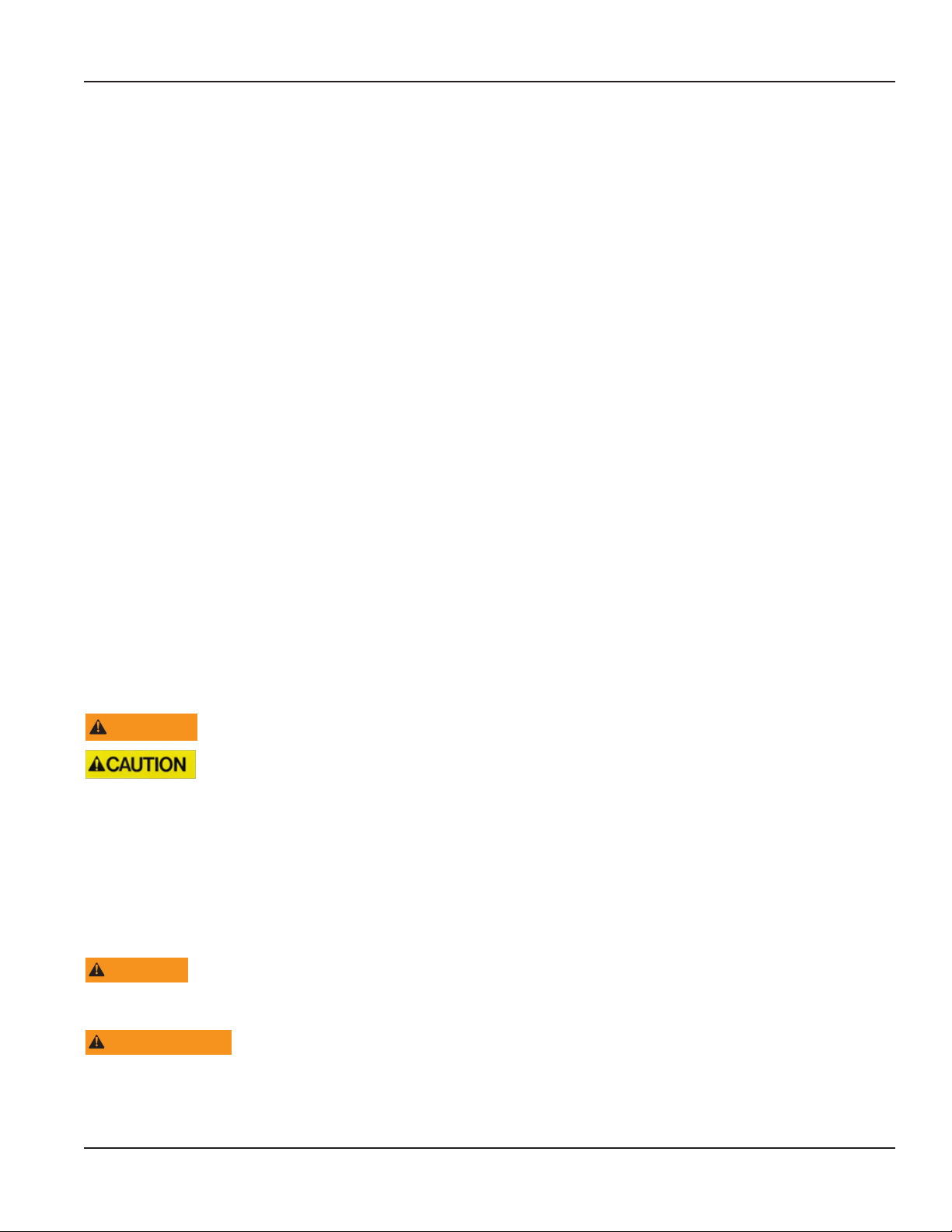
DIMENSIONS
Enclosure, Integral and Remote, Front View Integral Enclosure Side View Remote Enclosure Side View
6.00 in.
(152.40 mm)
2.68 in.
(68.07)
0.31 in.
(7.87 mm)
2.68 in.
(68.07)
0.38 in.
(9.65 mm)
5.55 in.
(140.97 mm)
0.65 in.
(16.51 mm)
Figure 2: Dimensions
Page 6 April 2019TTM-UM-02537-EN-04
Page 7
OPERATION
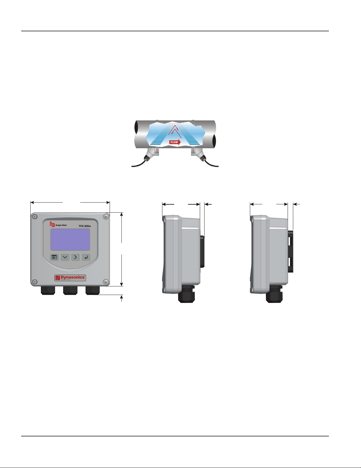
Keypad Operation on the Home Screen
The MENU/BACK key enters menu structure.
The DOWN ARROW key toggles between flow rate, flow total, velocity and flow rate with flow total.
The RIGHT ARROW key has no function.
The ENTER key has no function.
Operation
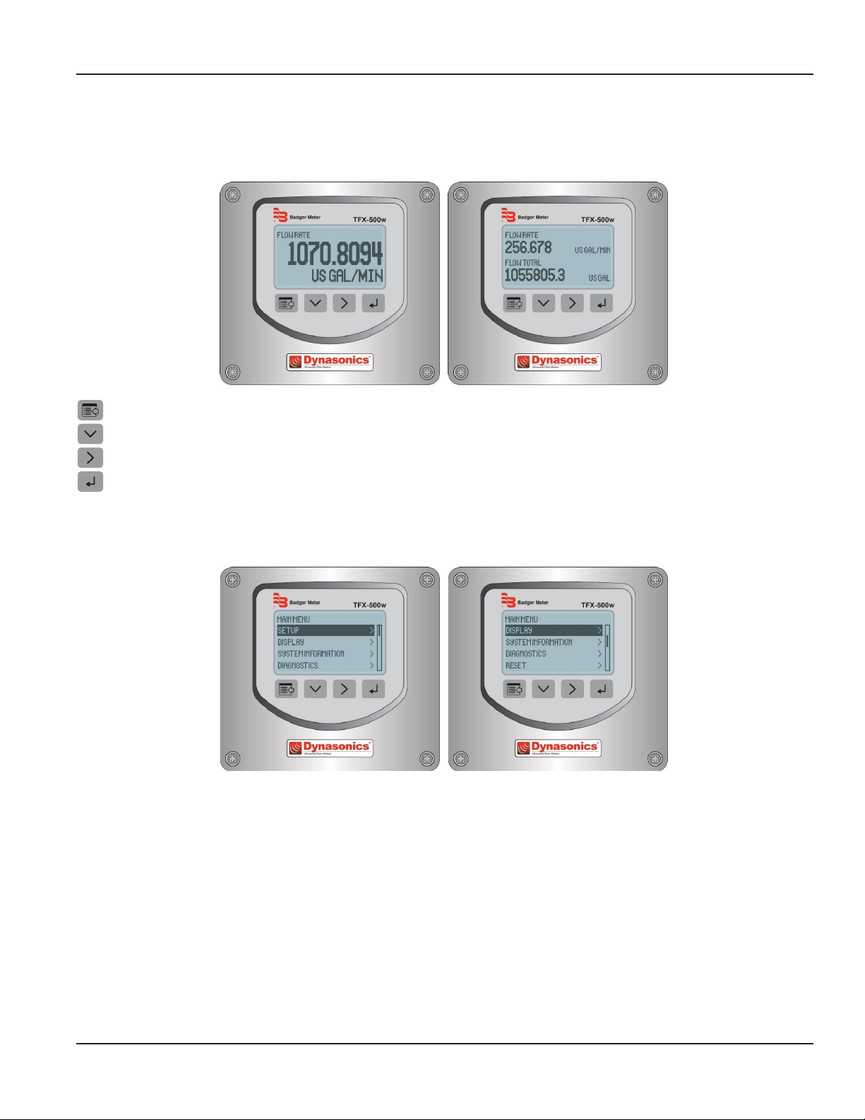
Keypad Operation in the Menu Structure
The cursor bar highlights the submenu or parameter that will be viewed or edited. The scroll bar on the right indicates the
relative position the cursor bar is at on the list when there are more than 4 items.
• MENU/BACK returns to parent menu (up a level). If at the Main (top level) menu, returns to the Home Screen.
• DOWN ARROW scrolls the list.
• RIGHT ARROW and ENTER have the same function in the menu structure and advance to the submenu or to
read/edit a parameter.
Page 7 April 2019 TTM-UM-02537-EN-04
Page 8
Operation
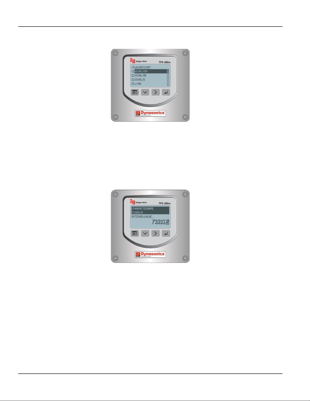
Selecting an Option in a Parameter Selection List
The active option in the parameter list has a filled-in box on the left side. The scroll bar on the right indicates the relative
position the cursor bar is at on the list when there are more than 4 items.
• DOWN ARROW scrolls the list.
• RIGHT ARROW and ENTER have the same function in the parameter selection list. Pressing either of these buttons selects
the option and the box on the left side fills in to show the item is selected.
• MENU/BACK exits parameter editing and returns to the parent menu (up a level).
Entering a Number
The parameter name and current value is displayed in the top portion of the screen. Edit the number on the bottom right of
the screen.
• MENU/BACK exits parameter editing and returns to parent menu (up a level). The parameter remains at the value displayed
in the top portion of the screen.
• DOWN ARROW cycles through the numbers and other options.
• RIGHT ARROW moves the cursor to the right. Once it reaches the rightmost digit or a space, the cursor moves to the
leftmost digit.
• ENTER accepts the value.
Page 8 April 2019TTM-UM-02537-EN-04
Page 9

INSTALLATION
Overview
Each of the installation steps that follow is explained in detail on page 10 through page 12 . The actual installation
procedures differ slightly, depending on whether the transducers are fixed or adjustable.
If the transducers are fixed, you will:
1. Install the transducers.
2. Install the transmitter.
3. Wire the transmitter.
4. Program the meter.
If the transducers are adjustable, you will:
1. Install the transmitter.
2. Wire the transmitter.
3. Set up the meter (select the optimum transmission mode, enter the site information, and enter the uid and
pipe properties).
4. Install the transducers.
5. Complete the meter programming.
Installation
Installation Considerations
Mount the transmitter in a location:
• Where little vibration exists.
• That is protected from corrosive fluids.
• That is within the transmitters ambient temperature limits: With display, –4…140° F (–20…60° C);
without display: –40…158° F (–40…70° C).
• That is out of direct sunlight. Direct sunlight may increase transmitter temperature to above the maximum limit.
Equipment Required
• Screwdrivers, wide blade and tiny blade (for securing wires to the terminal blocks)
• User manual for the transducers
• Four #8 or M4 screws, if mounting the transmitter on a wall
• Stainless steel banding straps, if mounting the transmitter on a pipe
Installing the Transducers
See the user manual for your particular transducer for installation instructions.
Page 9 April 2019 TTM-UM-02537-EN-04
Page 10
Installation
Installing a Meter with a Remote Transmitter and Fixed Transducers
• Locate the transmitter within the length of the transducer cables supplied or exchange the cable for one of proper length.
• See Figure 2 on page 6 for enclosure and mounting dimension details. Allow enough room for door swing, maintenance
and conduit entrances.
MPORTANTI
When routing wires to the transmitter, make sure the cables are not twisted, pinched or hanging loosely.
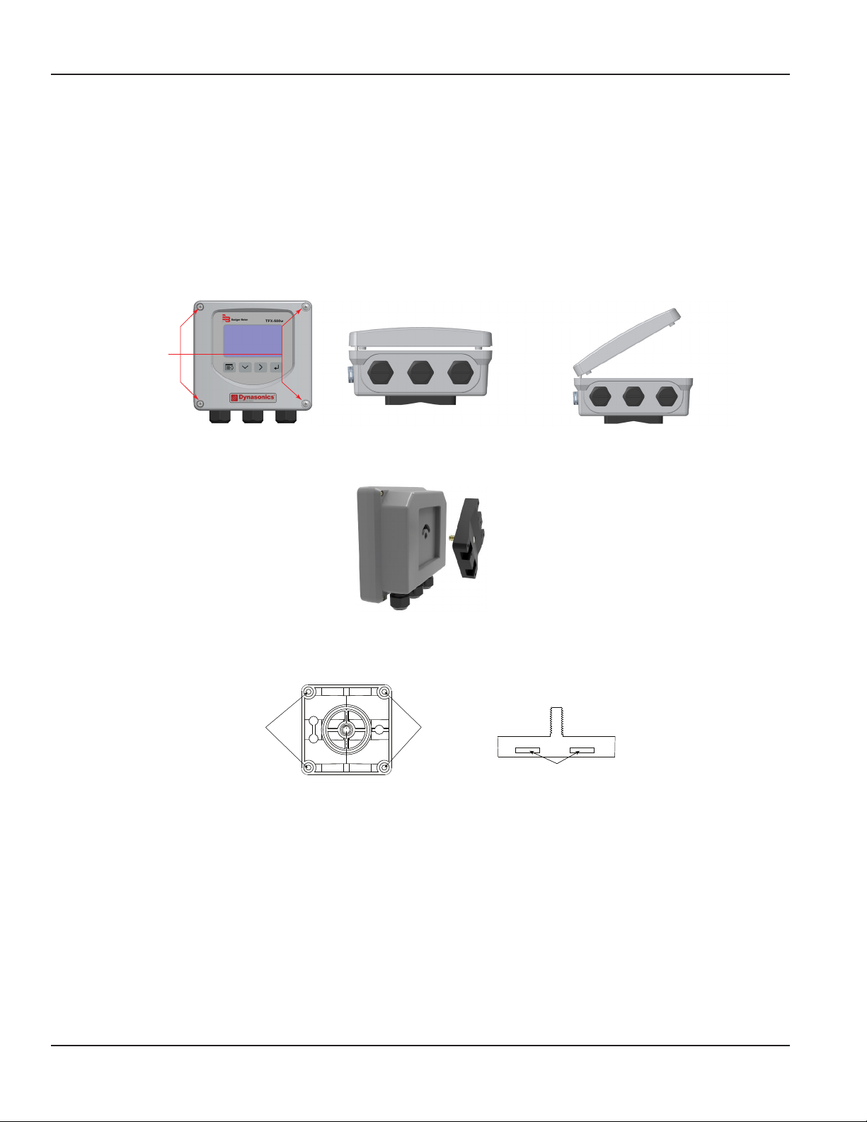
1. Install the xed transducers according to instructions in the transducer user manual.
2. Partially loosen the 2 enclosure captive screws on the left side of the transmitter cover. Completely loosen the 2 screws on
the right side. Grasp and lift the cover and open it to the left. The cover remains attached and the left screws act as a hinge.
Unscrew
Captive Screws
Figure 3: Captive cover screws Figure 4: Lift cover from base Figure 5: Open cover to the left
3. Unscrew the wingnut from the threaded stud on the inside back of the enclosure to release the adapter plate. Set aside
the wingnut.
Figure 6: Rotatable adapter plate
4. If necessary, rotate the adapter plate by 90° to accommodate the nal orientation of the transmitter.
5. Mount the adapter plate either to a wall (with 4 customer-supplied #8 or M4 screws) or to a pipe (with mounting straps).
Holes for
Screws
Figure 7: Wall mount Figure 8: Pipe Mount
Holes for
Screws
Holes for Straps
6. Use conduit holes where cables enter the enclosure from the bottom. Use plugs to seal any holes that are not used for
cable entry. A cable gland kit is included for inserting the transducer and power cables.
OTE:N Use NEMA 4 (IP-66) rated fittings/plugs to maintain the watertight integrity of the enclosure. Generally, the right
conduit hole (viewed from front) is used for power, the left conduit hole for transducer connections, and the center
hole is used for I/O wiring.
7. Install the wires through the gland nuts and connect the wires to the removable terminal blocks. See “Wiring the
Transmitter” on page13.
8. Wire the transducers to the transmitter.
9. Slide the meter enclosure over the threaded stud and secure it with the wingnut.
10. Plug the wired terminal blocks into the main board.
11. Reassemble the cover.
12. Set up the meter. See “Initial Meter Setup” on page16 for instructions.
Page 10 April 2019TTM-UM-02537-EN-04
Page 11
Installation
Installing a Meter with a Remote Transmitter and Adjustable Transducers
• Locate the transmitter within the length of the transducer cables supplied or exchange the cable for one of proper length.
• See Figure 2 on page 6 for enclosure and mounting dimension details. Allow enough room for door swing, maintenance
and conduit entrances.
MPORTANTI
When routing wires to the transmitter, make sure the cables are not twisted, pinched or hanging loosely.
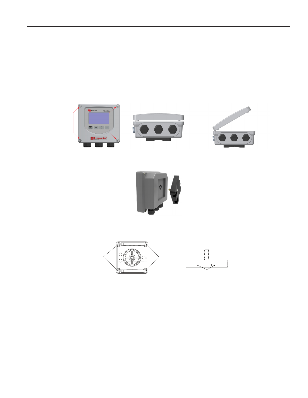
1. Partially loosen the 2 enclosure captive screws on the left side of the transmitter cover. Completely loosen the 2 screws on
the right side. Grasp and lift the cover and open it to the left. The cover remains attached and the left screws act as a hinge.
Unscrew
Captive Screws
Figure 9: Captive cover screws Figure 10: Lift cover from base Figure 11: Open cover to the left
2. Unscrew the wingnut from the threaded stud on the inside back of the enclosure to release the adapter plate. Set aside
the wingnut.
Figure 12: Rotatable adapter plate
3. If necessary, rotate the adapter plate by 90° to accommodate the nal orientation of the transmitter.
4. Mount the adapter plate either to a wall (with 4 customer-supplied #8 or M4 screws) or to a pipe (with mounting straps).
Holes for
Screws
Figure 13: Wall mount Figure 14: Pipe Mount
Holes for
Screws
Holes for Straps
5. Use conduit holes where cables enter the enclosure from the bottom. Use plugs to seal any holes that are not used for
cable entry. A cable gland kit is included for inserting the transducer and power cables.
OTE:N Use NEMA 4 (IP-66) rated fittings/plugs to maintain the watertight integrity of the enclosure. Generally, the right
conduit hole (viewed from front) is used for power, the left conduit hole for transducer connections, and the center
hole is used for I/O wiring.
6. Install the wires through the gland nuts and connect the wires to the removable terminal blocks. See “Wiring the
Transmitter” on page13.
7. Set up the meter. See “Initial Meter Setup” on page16 for instructions.
8. Install the adjustable transducers according to instructions in the transducer user manual.
9. Wire the transducers to the transmitter.
10. Slide the meter enclosure over the threaded stud and secure it with the wingnut.
11. Plug the wired terminal blocks into the main board.
12. Reassemble the cover.
Page 11 April 2019 TTM-UM-02537-EN-04
Page 12
Wiring the Transmitter
Installing a Meter with an Integral Transmitter
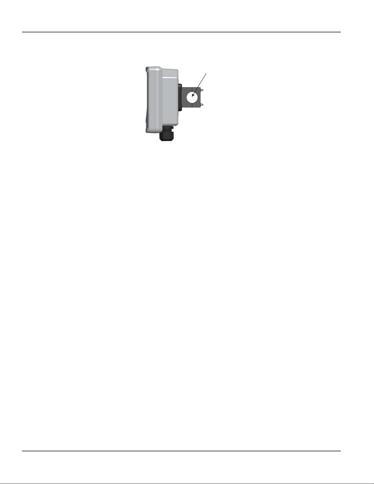
1. Install the meter on the pipe according to the instructions in the user manual for your particular transducer.
Pipe
Figure 15: Install the meter onto the pipe
2. Partially loosen the 2 enclosure captive screws on the left side of the transmitter cover. Completely loosen the 2 screws on
the right side. Grasp and lift the cover and open it to the left. The cover remains attached and the left screws act as a hinge.
3. If necessary, rotate the transmitter 180° by opening the cover, loosening the wing nut, repositioning the transmitter, and
reinstalling all of the connections.
4. Use conduit holes where cables enter the enclosure from the bottom. Use plugs to seal any holes that are not used for
cable entry. A cable gland kit is included for inserting the transducer and power cables.
OTE:N Use NEMA 4 (IP-66) rated fittings/plugs to maintain the watertight integrity of the enclosure. Generally, the right
conduit hole (viewed from front) is used for power, the left conduit hole for transducer connections, and the center
hole is used for I/O wiring.
5. Install the wires through the gland nuts and connect the wires to the removable terminal blocks. See “Wiring the
Transmitter” on page13.
6. Plug the wired terminal blocks into the main board.
7. Reassemble the cover.
Page 12 April 2019TTM-UM-02537-EN-04
Page 13
Wiring the Transmitter
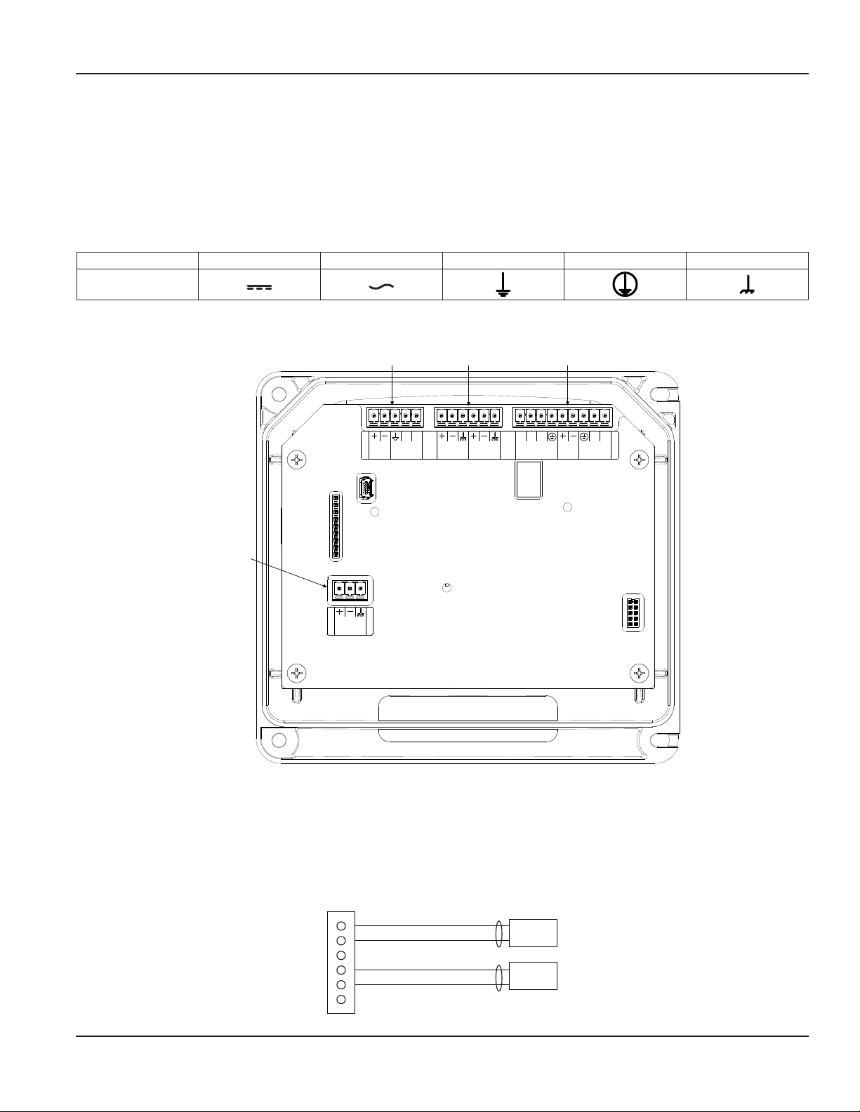
WIRING THE TRANSMITTER
IMPORTANT: Select field wiring means rated for 5° C above the maximum area temperature when it is possible that the
temperature will exceed 55° C.
To access terminal strips for wiring, loosen the 4 enclosure captive screws. Grasp and lift the cover and open it to the left. The
cover remains attached and the left screws act as a hinge.
Electrical Symbols
Function Direct Current Alternating Current Earth (Ground) Protective Ground Chassis Ground
Symbol
Figure 16: Electrical symbols
TB400
Power
Connector
9 - 28V DC
@ 5W (Max)
TB500
Digital I/O
Connector
TOTAL
RESET
ENC DOUT
ENC CLK IN
TB300
Transducer
Connector
UP
STREAM
DOWN
STREAM
24V OUT
Connector
4-20 OUT
4-20 LOOP
TB600
Output
RS-485
1 2
CONTROL
OUT
Figure 17: Wiring connectors
Wiring the Transducer
1. Guide the transducer terminations through the transmitter conduit hole in the bottom-left of the enclosure.
2. Secure the transducer cable with the supplied conduit nut (if exible conduit was ordered with the transducer).
3. The terminals within the transmitter are screw-down barrier terminals. Connect the wires at the corresponding screw
terminals in the transmitter. Observe upstream and downstream orientation and wire polarity. See Figure 18.
TB300 External Equipment
1
2
3
4
5
6
Figure 18: Upstream/downstream transducer
UP/TX Red
UP/TX Black
DN/TX Red
DN/TX Black
Page 13 April 2019 TTM-UM-02537-EN-04
Page 14
Wiring the Transmitter
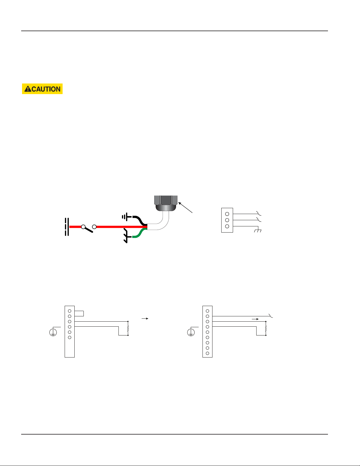
OTE:N Transducer cables have two wire-color combinations. For the blue and white combination, the blue wire is positive
(+) and the white wire is negative (–). For the red and black combination, the red wire is positive (+) and the black
wire is negative (–). The transducer wires are labeled to indicate which pair is upstream or downstream.
4. Connect power to the screw terminal block in the transmitter using the conduit hole in the center of the enclosure. Use
wiring practices that conform to local and national codes such as The National Electrical Code Handbook in the U.S.
ANY OTHER WIRING METHOD MAY BE UNSAFE OR CAUSE IMPROPER OPERATION OF THE TRANSMITTER.
OTE:N This transmitter requires clean electrical line power. Do not operate this transmitter on circuits with noisy
components (such as fluorescent lights, relays, compressors, or variable frequency drives). Do not use step-down
transformers from high voltage, high amperage sources. Do not to run signal wires with line power within the same
wiring tray or conduit.
DC Power Connections
The transmitter may be operated from a 9…28V DC source, as long as the source supplies a maximum of 5 Watts of power.
Connect the DC power to 9…28V DC In, power ground, and chassis ground, as in Figure 19.
OTE:N DC-powered transmitters are protected from major catastrophe with an internal 1.5 Amp SLO-BLO fuse. If this fuse is
blown, the transmitter must be inspected and the fuse replaced at the factory.
IMPORTANT: A Class II DC power supply is required.
9…28V DC
Switch
or
Circuit
Breaker
Power
Common
Chassis
Ground
Power
Figure 19: DC power connections
TB400 External Equipment
1
2
3
Power Supply (9 . . . 28V DC)
Power Supply (0V)
Chassis Ground
4…20 mA Output Wiring
The 4…20 mA output transmits an analog current signal that is proportional to system flow rate. The 4…20 mA output can be
internally or externally powered and can span negative to positive flow rates.
DC-powered transmitters use the DC power supply voltage to drive the current loop. The current loop is not isolated from DC
ground or power.
TB600
24V DC
(42 mA) max.
Figure 20: Typical 4 . . . 20 mA interface using internal isolated 24V DC source Figure 21: Typical 4 . . . 20 mA interface using external isolated 24V DC source
1
2
3
4
External Equipment
Current Output
800 Ohms max.
TB600
1
2
3
4
No Connect
Current Output
External Equipment
24V DC (30V DC max.)
800 Ohms max.
Page 14 April 2019TTM-UM-02537-EN-04
Page 15

Wiring the Transmitter
Digital Outputs Wiring
TB600
TB600
1
2
3
4
5
6
7
8
9
External Equipment
(15 . . . 30V DC)
V DC
R-PullupR-Pullup
Control Out1
Control Out2
ISO Ground
R12
10 Ohms
ISO 24V
ISO Ground
1
2
3
4
5
6
7
8
9
External Equipment
Control Out1
Control Out2
Figure 22: Typical control out 1 & 2 interface with internal pullups active Figure 23: Typical control out 1 & 2 interface with external pullups passive
RS485 Output
The RS485 feature allows up to 126 transmitters to be placed on a single three-wire cable up to 4000 feet. All transmitters are
assigned a unique numeric address that allows all of the transmitters on the cable network to be independently accessed.
Either Modbus RTU or BACnet MS/TP protocol is used to interrogate the transmitters.
Flow rate and total can be monitored over the digital communications bus.
When a USB programming cable is connected, the RS485 and frequency outputs are disabled.
TB600
Digital I/O Wiring
Terminator Resistors
(Enabled through Parameter Setting)
60.4 Ohms
A B
60.4 Ohms
5
6
External Equipment
RS485 +
RS485 −
Figure 24: Typical RS485 interface
TB500
1
2
3
4
5
Reset Total +
Reset Total -
Push-button
5…30V DC
TB500
1
2
3
4
5
NOTE: Non-isolated
DGND (Black Wire)
Endpoint VccClk In (Red Wire)
Endpoint Data Pulse Out (Green Wire)
Figure 25: Digital I/O—reset totalizer Figure 26: Digital I/O—BMI encoder interface
AquaCUE/BEACON
Endpoint
Page 15 April 2019 TTM-UM-02537-EN-04
Page 16

Menu Map
Initial Meter Setup
You can set up the meter using the TFX-500w keypad or the SoloCUE Flow Device Manager software. This document
addresses procedures using the TFX-500w keypad. To use SoloCUE, see the "SoloCUE Flow Device Manager Installation Guide"
available at www.badgermeter.com.
When you start the meter for the first time, you must select a language, press ENTER, then press MENU/BACK to get to
BASIC SETUP.
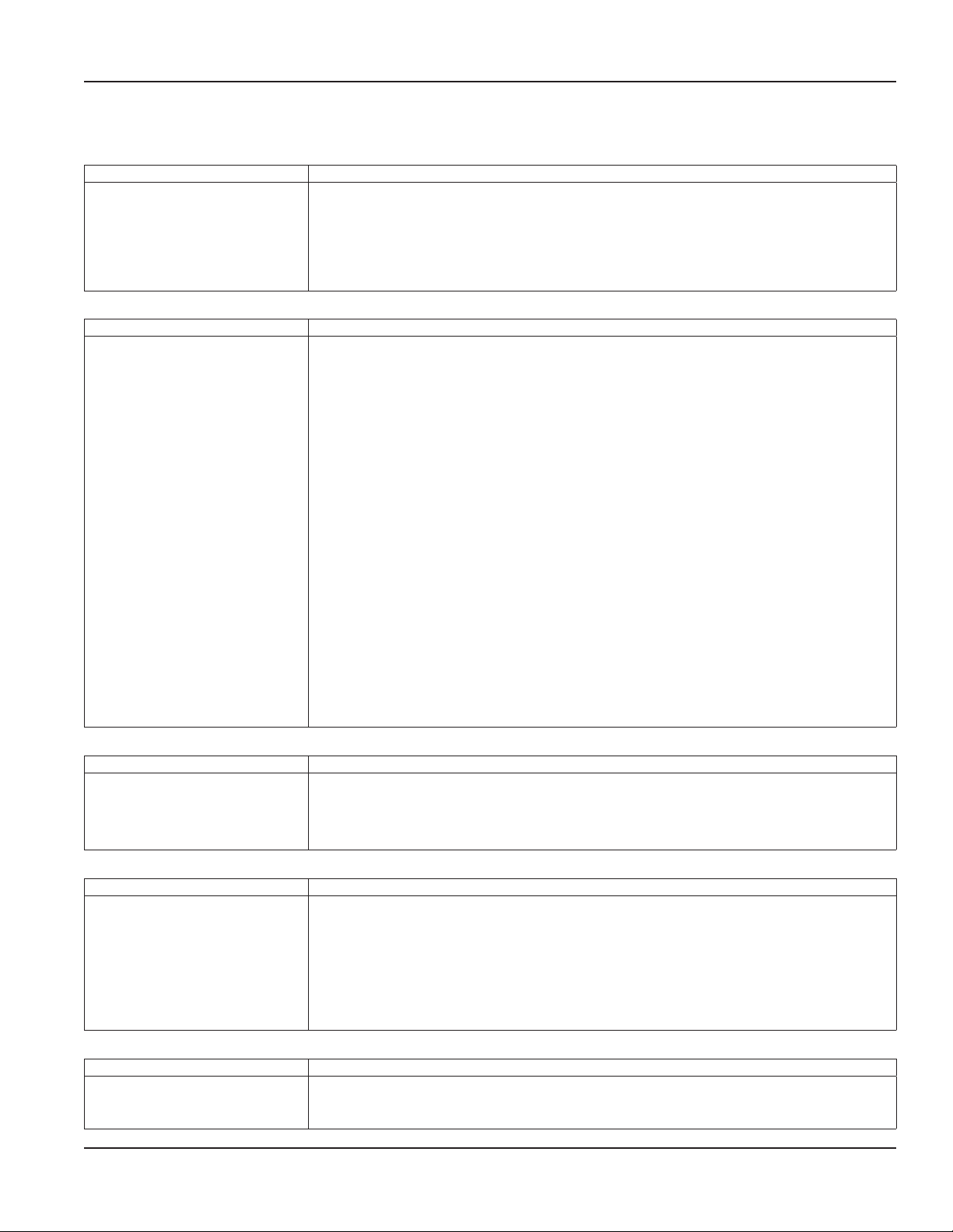
In BASIC SETUP, program the parameters in the table below using the transmitter's keypad. Enter the pipe characteristics,
transducer and mounting in the SETUP > METER submenus. For integral mount meters with DTTS/C transducers, these
parameters are already set at the factory and you can skip these steps.
For in-depth parameter programming, see “Parameter Descriptions by Menu” on page18.
Submenu Parameter Action
PIPE MATERIAL Select the material of the pipe.
Select the pipe schedule for ANSI pipes or manual entry of the outside diameter (O.D.) in
PIPE TYPE
PIPE SIZE NOMINAL
PIPE
PIPE SIZE and WALL
THICKNESS
LINER THICKNESS
and LINER MATERIAL
(optional)
I.D. SIZE The calculated inner diameter based on settings.
DTTN/DTTR 1 MHZ
TRANSDUCER
MOUNTING
OR
DTTS/DTTC TYPE DTTS/DTTC TYPE substituted for MOUNTING when TRANSDUCER > DTTS/DTTC is selected.
DTTSU 2 MHZ
DTTS/DTTC 2 MHZ
DTTJ/K EASYRAIL 1 MHZ
Z-PATH
V-PATH
W-PATH
millimeters or inches. If you select manual entry, you will need to enter the pipe wall thickness.
The available options are based on the pipe material selected. If you do not see a valid option,
check the pipe material setting.
When you select an ANSI pipe schedule, you need to select the nominal pipe size in inches. If
you do not see a valid option, check the pipe type.
When you select MANUAL for Pipe Type, enter the outer diameter and wall thickness of the
pipe. The units are based on whether MANUAL INCHES or MANUAL MM was selected for the
Pipe Type.
If there is a liner in the pipe, enter the liner thickness and select the liner material. The units are
based on the Pipe Type. If you do not see a valid option, check the Pipe Type.
If the meter was ordered as a single part number, the transducers are configured at the
factory. Otherwise, select the transducer model from the list. The model is marked on one of
the transducer heads. If you do not see the transducer model in the list, select a transducer
with the same frequency.
Select the mounting path to match the required setup. See the transducer user manual to
select the best path.
SPACING SPACING CALCULATED View to see the correct spacing for the transducers.
UNITS
FLOW SETUP
CALIBRATION
SET ZERO Confirmation screen
Page 16 April 2019TTM-UM-02537-EN-04
See “Setup > Units” on
page18.
See “Setup > Meter
> Flow Setup” on
page21.
See “Setup > Meter
> Calibration” on
page30.
Select the units and format of flow rate, total and velocity.
Select flow direction, low flow cutoff, signal cutoffs and filtering.
Check whether Factor Mode is set to Factory or Field. If it is Factory, compare the calibration
factor on the transducers. If they do not match, change Factor Mode to Field.
If Factor Mode is Field, enter the transducer calibration factor into Scale Factor.
1. Check that the pipe is full of liquid and not owing. Flow must be absolutely zero.
2. Securely close any valves and allow time for settling to occur.
3. Select SET ZERO and press OK to set the new zero.
Page 17
NOTE:
Menu Map
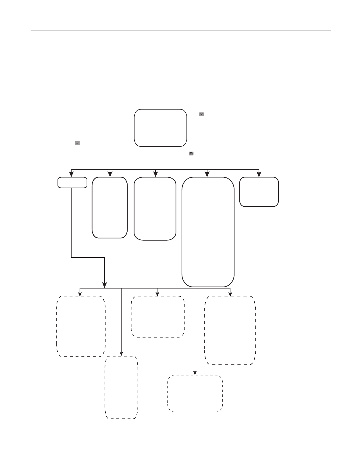
MENU MAP
Passcode levels for write access to each menu are as follows:
(O) = Operator, Service or Admin
(S) = Service or Admin
(A) = Admin
If no passcode is entered, all parameters can still be read.
Press
to toggle
the options.
Press
to access
this menu.
Press
to select
a main
menu
option.
HOME SCREEN
Flow Rate
Flow Total
Velocity
Flow Rate & Flow Total
MAIN MENU
Setup Display Information Diagnostics Reset
(O)
Language
Display Tag I.D.
Brightness
Contrast
Dimmer
Dimmer Level
Timeout
Vendor
Model
P.N.
S.N.
FW Version
Cal. Date
Date Code
Tag ID
(S)
Signal Strength
History
Delta Time Filtered
Flow Rate Raw
Fluid Sound Speed
Delta Time Raw
Current Output
Output #1 Status
Output #2 Status
Input Status
Total Overow Count
Passcode Level
Clear History
Factory Reset
Reboot
(O)
Reset Flow Total
Unlatch Alarms
Units
(O)
Flow Units
Flow Decimals
Flow Total Mode
Flow Total Units
Flow Total Decimals
Velocity Units
Display Mode
Meter
(S)
Transducer
Mounting
Pipe
Spacing
Flow Setup
Shunt
Calibration
Input/Output
(S)
Current Output
Output #1
Output #2
Input
Communications
Passcode
Setup
(A)
Passcode Recovery
Temporary Passcode
Security
Set Admin
Set Operator
Set Service
Logout Timeout
(S)
Network Type
Settings
Endpoint
Page 17 April 2019 TTM-UM-02537-EN-04
Page 18
Parameter Descriptions by Menu
PARAMETER DESCRIPTIONS BY MENU
Main Menu Structure
The transmitter’s firmware has a hierarchical menu structure. See "Menu Map" on page17 for a visual path to the parameters.
The five Main Menus used in the transmitter firmware are as follows:
Menu Function
SETUP Contains all of the configuration parameters for initially programming the transmitter to measure flow
DISPLAY Configures transmitter display functions
INFORMATION Displays system information, such as the model number and firmware version
DIAGNOSTICS Displays system status and allows you to clear the history, reset to factory defaults and reboot the system
RESET Resets the flow total or unlatches alarms
The following pages define the configuration parameters located in each of the menus.
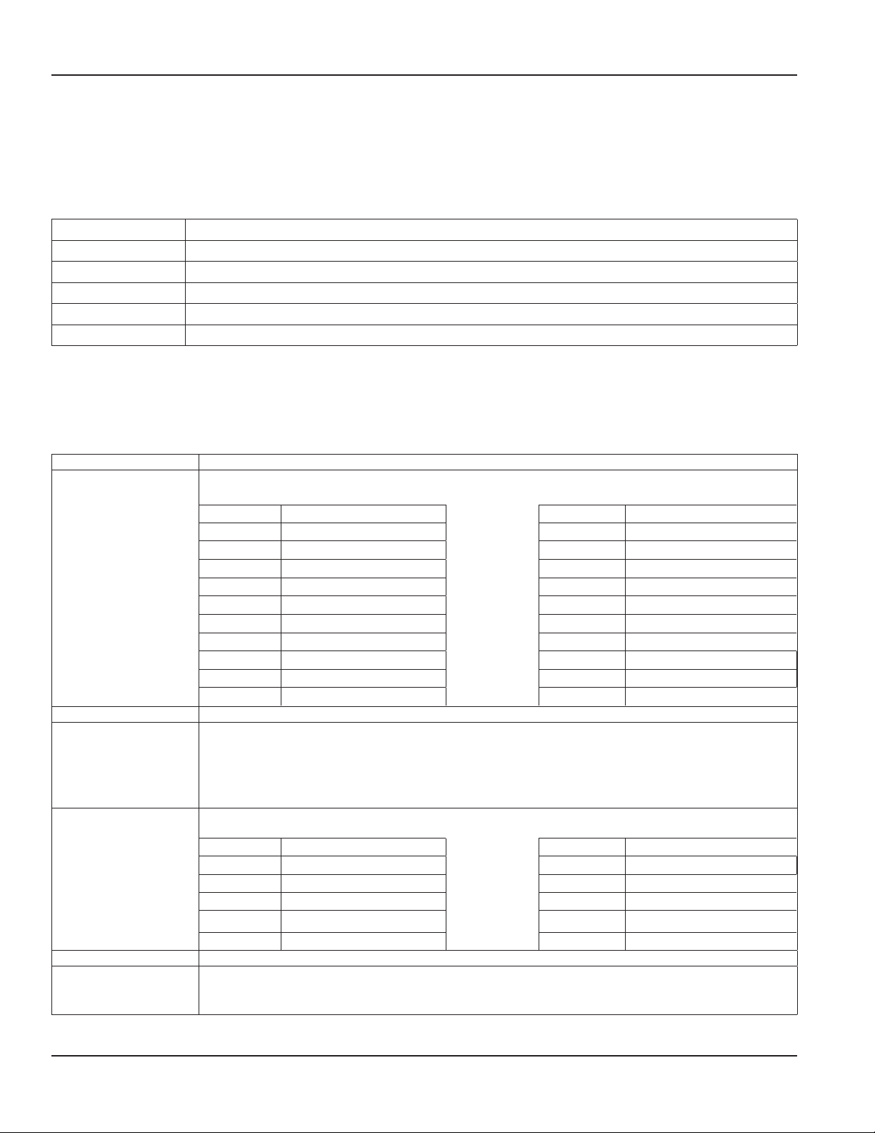
Setup > Units
Use SETUP > UNITS to define the measurement standards for the transmitter.
An asterisk (*) indicates the parameter default.
Units Submenus Options/Descriptions
Select the flow rate units/interval displayed on the Home Screen. FLOW UNITS are automatically converted into
the selected option.
Option Units/Interval Option Units/Interval
AC FT/D Acre Feet/Day GAL/S Gallons/Second
L/S Liters/Second GAL/MIN Gallons/Minute
L/MIN Liters/Minute GAL/H Gallons/Hour
FLOW UNITS
FLOW DECIMALS This is a numeric entry for the number of decimal places to display. Default is 2. Options are 0…7
FLOW TOTAL MODE
FLOW TOTAL UNITS
FLOW TOTAL DECIMALS This is a numeric entry for the number of decimal places to display. Default is 0. Options are 0…7.
VELOCITY UNITS
L/H Liters/Hour MG/D Million Gallons/Day
M3/S Cubic Meters/Second IG/S Imperial Gallons/Second
M3/MIN Cubic Meters/Minute IG/MIN Imperial Gallons/Minute
M3/H Cubic Meters/Hour IG/H Imperial Gallons/Hour
FT3/S Cubic Feet/Minute BBL/MIN Barrel/Minute
FT3/MIN Cubic Feet/Minute MIG/D Million Imperial Gallons/Day
FT3/H Cubic Feet/Hour BBL/D Barrel/Day
*GROSS FLOW Any ow in forward and reverse direction.
FORWARD FLOW
REVERSE FLOW
NET FLOW Forward ow minus reverse ow. A negative total results when reverse ow is greater than
forward ow..
Select the units for the flow total displayed on the Home Screen. FLOW TOTAL UNITS are automatically converted
into the selected option:
Option Units Option Units
GAL Gallons MIGAL Million Gallons
MGAL Million Gallons L Liter
IGAL Imperial Gallons HL Hectoliter
AC-FT Acre Feet M3 Cubic Meters
BBL Barrel FT3 Cubic Feet
Select the units for the velocity displayed on the Home Screen.
*FT/S Feet/Second
M/S Meters/Second
Page 18 April 2019TTM-UM-02537-EN-04
Page 19

Units Submenus Options/Descriptions
Select whether to display the flow rate, flow total, velocity or both flow rate and flow total on the display.
Alternatively, you can change the display from the Home Screen by pressing the DOWN button.
DISPLAY MODE
*FLOW RATE
FLOW TOTAL
VELOCITY
FLOW/TOTAL
Setup > Meter
An asterisk (*) indicates the parameter default.
Meter Submenus Options/Descriptions
Select the transducer type:
DTTSU 2 MHZ Option UZ when ordered with the TFX-500w meter
TRANSDUCER
MOUNTING
DTTS/DTTC TYPE
DTTS/DTTC 2 MHZ Options CA…CS and CZ when ordered with the TFX-500w meter
DTTJ/K EASYRAIL 1 MHZ Options JZ and KZ when ordered with the TFX-500w meter
DTTN/DTTR 1 MHZ Options NZ, WZ and RZ when ordered with the TFX-500w meter
For mounting options, see the transducer user manual.
Z PATH
*V PATH
W PATH
DTTS/DTTC TYPE is substituted for MOUNTING when TRANSDUCER DTTS/DTTC is selected as the transducer type.
CA: 1/2 IN ANSI CJ: 1-1/4 IN COPPER
CB: 3/4 IN ANSI CK: 1-1/2 IN COPPER
CC: 1 IN ANSI CL: 2 IN COPPER
CD: 1-1/4 IN ANSI CM: 1/2 IN SS TUBE
CE: 1-1/2 IN ANSI CN: 3/4 IN SS TUBE
CF: 2 IN ANSI CP: 1 IN SS TUBE
CG: 1/2 IN COPPER CQ: 1-1/4 IN SS TUBE
CH: 3/4 IN COPPER CR: 1-1/2 IN SS TUBE
CT: 1 IN COPPER CS: 2 SS IN TUBE
Parameter Descriptions by Menu
Page 19 April 2019 TTM-UM-02537-EN-04
Page 20

Parameter Descriptions by Menu
Setup > Meter > Pipe
An asterisk (*) indicates the parameter default.
Pipe Submenus Options/Descriptions
PIPE MATERIAL
PIPE TYPE For the best accuracy, measure the outer diameter and wall thickness with a gauge and select MANUAL INCHES
PIPE SIZE Available only when PIPE TYPE is MANUAL. Numeric entry; min. 0.5 in. (15 mm), max. 10 in. (250 mm)
PIPE SIZE NOMINAL PIPE SIZE NOMINAL is substituted for PIPE SIZE when a schedule/tubing/class is selected.
WALL THICKNESS Numeric entry; *min. 0.00, max. 5 in. (125 mm); TFX-500w limited to 1 in.
LINER MATERIAL
LINER THICKNESS Numeric entry; min. 0.00, max. 20 in. (500 mm)
I.D. SIZE Numeric display *1.682 in.
*STAINLESS 316 CARBON STEEL PFA TEFLON
STAINLESS 347 COPPER PVC CPVC
STAINLESS 410 IRON - CAST STAINLESS 302/303
STAINLESS 430 IRON - DUCTILE STAINLESS 304
ALUMINUM HD POLYETHYLENE STAINLESS 304L
BRASS NAVAL LD POLYETHYLENE PVDF
or MANUAL MM.
If you do not have a gauge, you can select an ASME/ANSI or ASTM definition.
If stainless steel pipe, carbon steel, PVC, CPVC material is selected, the following pipe schedules are also
available:
SCHEDULE STD SCHEDULE 80 CLASS A CLASS 50
SCHEDULE 5 SCHEDULE 100 CLASS B CLASS 51
SCHEDULE 10 SCHEDULE 120
SCHEDULE 20 SCHEDULE 140
SCHEDULE 30 SCHEDULE 160
SCHEDULE 40 SCHEDULE 180
SCHEDULE 60 SCHEDULE STG
If copper material is selected, the following types are also available.
TYPE K TYPE L TYPE M PIPE SIZE
If cast iron pipe material is selected, the following classes are also available:
CLASS A CLASS E
CLASS B CLASS F
CLASS C CLASS G
CLASS D CLASS H
If ductile iron pipe material is selected, the following classes are also available:
CLASS 50 CLASS 54
CLASS 51 CLASS 55
CLASS 52 CLASS 56
CLASS 53
If aluminum or brass naval material, enter the pipe size in inches.
Enumeration based on schedule; Min 1/2 inch, Max 10 inch
1/2, 3/4, 1, 1-1/4, *1-1/2, 2, 2-1/2, 3, 3-1/2, 4, 5, 6, 8, 10
WALL THICKNESS is only useful for MANUAL METRIC and MANUAL INCHES and DTTS tubing pipe types. It can be
skipped for pipe schedule, tubing and classes.
NONE HD POLYETHYLENE TAR EPOXY
ACRYLIC LD POLYETHYLENE PFE TEFLON
ASBESTOS CEMENT POLYPROPYLENE GLASS PYREX
EBONITE POLYSTYRENE FIBERGLASS EPOXY
MORTAR RUBBER
Page 20 April 2019TTM-UM-02537-EN-04
Page 21

Parameter Descriptions by Menu
Setup > Meter > Spacing
This menu is available only for adjustable spacing transducers, not fixed spacing. An asterisk (*) indicates the default.
Spacing Submenu Options/Descriptions
MODE *SPACING CALCULATED
The spacing required between two transducers based on the pipe parameters. Take this measurement
CALCULATED
between the lines scribed into the side of the transducers of use the scale on the rails, if used. See the
transducer user manual.
Numeric display 0…300 units in. or mm based on PIPE SIZE selection. *0.954 in.
Setup > Meter > Flow Setup
An asterisk (*) indicates the parameter default.
Flow Setup Submenus Options/Descriptions
DIRECTION
BIDIRECTIONAL
LOW FLOW CUTOFF Numeric entry. Units and decimals are based on FLOW RATE UNITS. Zero and positive values. *0.0
SIGNAL CUTOFF *30%
SIGNAL HIGH *90%
MINIMUM FLOW -100,000
MAXIMUM FLOW 100,000
DAMPING *40 seconds
SENSITIVITY *60%
HYSTERESIS *5%
BAD DATA REJECTION *3
FILTER METHOD *Adaptive
WAVE
*FORWARD
REVERSE
*ENABLED
DISABLED
For detailed information on these parameters,
see "Filter Parameters" following this table.
• *AUTO automatically selects waveform based on flow speed and signal quality.
• SIN CARROT TOP is best for low speed flow.
• BEST BARKER is best for high speed flow.
Filter Parameters
Filter Method (Default: Adaptive)
The TFX-500w flow meter offers three levels of signal filtering:
• None imposes no filtering on the signal from the transducers.
• Simple with Rejection uses Damping and Bad Data Rejection to filter the flow data.
• *Adaptive filtering allows the meter’s software routines to alter the filtering, depending on the variability of the
transducer’s signal. The Adaptive filter uses a combination of Damping, Bad Data Rejection, Sensitivity and Hysteresis to
modify the flow input data.
Damping (Range 0…100 Seconds; Default: 40 Seconds)
Damping is the approximate amount of time the filtering routines use to attain a 99% stable rate value. Generally, the higher
the damping value, the more stable the rate readings are—but at the expense of response time.
Sensitivity (Range 0…100%; Default: 60%)
Sensitivity determines how fast the adaptive ltering responds to a change in rate. Increasing the sensitivity decreases the
ltering, which allows the display to respond to rate changes more rapidly.
Hysteresis (Range 0…25%; Default: 5%)
Hysteresis creates a window around the average flow measurement reading, defining the limits at which the automatic
damping increases occur. If the rate varies within the hysteresis window, greater damping occurs up to the maximum values
set by the flow filter Damping entry. The filter also establishes a flow rate window where measurements outside of the
window are captured by the Bad Data Rejection window. Enter the value as a percentage of actual flow rate.
For instance, a Hysteresis setting of 5% allows the flow to vary ± 5% from the currently established flow rate without
automatically decreasing the value of the Damping.
Page 21 April 2019 TTM-UM-02537-EN-04
Page 22

Parameter Descriptions by Menu
For example, if the average flow rate is 100 gpm and the Hysteresis is set to 10%, a filter window of 90…110 gpm is
established. Successive flow measurements that reside within that window are recorded and averaged in accordance with the
Damping setting. Flow readings outside of the window are rejected or accepted in accordance with the
Bad Data Rejection setting.
Filter settings for this example:
Filter Method Adaptive
Damping 40 seconds
Sensitivity 60%
Hysteresis 10%
Bad Data Rejection 3
150
Flow Within
Hysteresis Limit
110
±10% Hysteresis
Limit
100
90
50
Flow
0
Figure 27: Hysteresis window
Bad Data Rejection (Range 0…10 Samples; Default: 3)
The Bad Data Rejection setting is related to the number of successive readings that must be measured outside of a the
Hysteresis value before the flow meter considers the new flow value valid. In this example, a Hysteresis setting of 10% produces
a ± 10% band centered on the current valid flow rate of 100 gpm.
The Bad Data Rejection setting is the number of successive samples that must be outside of the Hysteresis window before
the flow meter considers the change in flow as real. Larger values are entered into the Bad Data Rejection window when
measuring liquids that contain gas bubbles, as the gas bubbles tend to disturb the ultrasonic signals and cause more
extraneous flow readings to occur. Larger Bad Data Rejection values tend to make the flow meter less responsive to rapid
changes in actual flow rate.
In Figure 29 on page 23, flow data falls outside the flow Hysteresis window but does not reach the minimum time specified in
the Bad Data Rejection window. When data appears that is outside the Hysteresis band and shorter than the Bad Data Rejection
window time, the data is rejected.
Page 22 April 2019TTM-UM-02537-EN-04
Page 23

150
Parameter Descriptions by Menu
3 Samples Outside
Hysteresis Limit
110
1 2 3
Flow Outside
Hysteresis Limit
100
90
Sample
Limits
Bad Data Rejection
Window
±10% Hysteresis
Limit
50
Flow
0
Figure 28: Bad data (rejection)
The flow rate is again outside the original ±10% Hysteresis window, but the data exists for a time period greater than the
Bad Data Rejection window. In this instance, the meter interprets the data as a new valid flow rate and moves the Hysteresis
window to correspond with the new established flow rate.
150
Old
±10% Hysteresis
Limit
110
4 Samples Outside
Hysteresis Limit
Flow Outside Original
Hysteresis Limit
100
90
1 2 3 4
50
0
Setup > Meter > Shunt
An asterisk (*) indicates the parameter default.
Shunt Submenu Options/Descriptions
Changing the SHUNT attenuates the received wave. If the signal strength is too low or too oversaturated (too
high), adjust the SHUNT setting. The 10 Ohm setting attenuates the most.
SHUNT
• 10 Ohm, minimize signal
• 26.1 Ohm, mid-range signal
• *NONE, maximize signal
Bad Data
Rejection Window
New
±10% Hysteresis
Limit
Flow
Figure 29: New valid flow data
Page 23 April 2019 TTM-UM-02537-EN-04
Page 24

Parameter Descriptions by Menu
Setup > Meter > Calibration
An asterisk (*) indicates the parameter default.
Calibration Submenus Options/Descriptions
FACTOR MODE
FACTORY SETTINGS
SET ZERO SET ZERO confirmation screen. Select OK or CANCEL.
ZERO VALUE Numeric display ##.### ns
SCALE FACTOR
*FACTORY
FIELD
ZERO
CAL FACTOR Numeric display #.*1.000 ns.
Numeric entry.
Default is 1.00
Set Zero Procedure
SET ZERO removes the No Flow transit time offset. This is also referred to as Zeroing the meter.
Because every flow meter installation is slightly different and sound waves can travel in slightly different ways through these
various installations, it is important to remove the zero offset at zero flow to maintain the meter’s accuracy. To establish
Zero flow and eliminate the offset:
1. The pipe must be full of liquid.
2. Flow must be absolutely zero. Securely close any valves and allow time for any settling to occur.
3. Press SET ZERO once.
Selects whether to use FACTORY calibration or to substitute a FIELD value entered
after a meter is installed.
The zero offset entered during factory calibration. ZERO is for reference only and
most likely the ZERO VALUE for your installation will be different from the factory
ZERO. Numeric display *0.000 ns.
The factor used for linearizing the flow rate calculation when FIELD is selected for
FACTOR MODE.
Factor Mode Procedure
The TFX-500w flow meter can be shipped as a transmitter and transducer set or the transmitter and transducers can be
shipped separate items. When it ships as a flow meter set, the meter is calibrated at the factory with CAL FACTOR (calibration
factor) set for the transducers. When the transmitter and transducers ship as separate items, the transducer calibration factor
printed on the transducer label must be entered into the transmitter as the SCALE FACTOR.
To enter the SCALE FACTOR:
1. Change the FACTOR MODE from FACTORY to FIELD.
2. For SCALE FACTOR, enter the calibration factor.
Field Calibration Procedure
To calibrate the TFX-500w flow meter, use a master meter or gravimetric test stand.
1. Set FACTOR MODE to FIELD.
2. Verify SCALE FACTOR is set to 1.
3. Run calibration test.
4. Calculate the SCALE FACTOR.
SCALE FACTOR = (actual flow)/(meter flow rate) or (actual total)/(meter total)
5. Enter the SCALE FACTOR.
Page 24 April 2019TTM-UM-02537-EN-04
Page 25

Parameter Descriptions by Menu
Setup > Input/Output >Current Output
The current output, reset input and frequency/pulse/status output can be set up through the SETUP > INPUT/OUTPUT menus.
An asterisk (*) indicates the parameter default.
Current Output Submenus Options/Descriptions
*FLOW RATE
VELOCITY
OUTPUT SOURCE
RANGE
MIN VALUE
MAX VALUE
TEST CURRENT
TRIM 4 mA
TRIM 20 mA
SIGNAL STRENGTH
TEST MODE
DISABLED
*4-20 mA
0-20 mA
Enter the value of the reading at 4 mA. Can also be the setting for the 0 mA setpoint when 4-20 mA RANGE is
selected. Units and decimal places based on parameter selected. Negative numbers accepted.
Enter the value of the reading at 20 mA. Units and decimal places based on parameter selected. Negative
numbers accepted.
Available only when OUTPUT SOURCE is in TEST MODE. Default 12.00 mA. To check the wiring to the control
system or gauge, you can override the current output with a fixed current. Numeric entry mA. 0…22 mA.
Available only when OUTPUT SOURCE is in TEST MODE. Set the test current to 4 mA. Adjusts output until PLC/
DCS/BAS reads 4 mA.
Available only when OUTPUT SOURCE is in TEST MODE. Set the test current to 20 mA. Adjusts output until
PLC/DCS/BAS reads 20 mA.
Select the reading to be assigned to the 4…20 mA output.
Page 25 April 2019 TTM-UM-02537-EN-04
Page 26

Parameter Descriptions by Menu
Setup > Inputs/Output > Output #1 (or Output #2)
Output #1 and output #2 can operate independently as a frequency, totalizer pulse, direction status or alarm status output.
In the SETUP > INPUT/OUTPUTS > OUTPUT #1 (OR OUTPUT #2) > MODE menu, select the MODE of operation. Then go to the
PARAMETERS menu to set up the operation for that MODE.
An asterisk (*) indicates the parameter default.
Output #1 Submenus Options/Descriptions
*FREQUENCY
PULSE TOTAL
MODE
PARAMETERS
(Frequency Mode)
PARAMETERS
(Pulse Total Mode)
FLOW DIRECTION
ALARM
DISABLED
OUTPUT
SOURCE
VALUE AT
0 HZ
MAX VALUE
MAX
FREQUENCY
TEST
FREQUENCY
OUTPUT
SOURCE
SCALING
FAC TOR
PULSE
WIDTH
PULSE STATE
*FLOW RATE
VELOCITY
TEST MODE
Numeric entry. Units based on
parameter selected. Negative
numbers accepted. Default -5000.
Numeric entry. Units based on
source selected. Negative numbers
accepted. Default 5000.
Numeric entry. Units in Hz.
Default 1 kHz.
Available when TEST MODE is selected for OUTPUT SOURCE. To check the wiring to the control
system or device, you can override the frequency output with a fixed frequency.
*POSITIVE FLOW
NEGATIVE FLOW
BIDIRECTIONAL
Numeric entry. Units and decimal place based on flow rate selection. Default is 1 unit per pulse.
Enter the number of totalizer units per pulse. The totalizer unit is in the SETUP > MEASUREMENTS
menu. For example, if the totalizer unit is gallons, setting the PULSES/UNIT to 10 transmits 1 pulse
every 10 gallons. Setting the SCALING FACTOR to 0.1 transmits 1 pulse every 0.1 gallons.
Numeric entry 5…2000 ms. Default 50 ms. Enter the pulse width in milliseconds.
*PULSE LOW
PULSE HIGH
Select the reading to assign to the frequency output.
Enter the maximum flow rate or velocity frequency that
corresponds to maximum frequency flow rate or velocity. Can
be negative to indicate reverse flow. The units of Maximum
match the units in
SETUP > MEASUREMENTS > FLOW UNITS.
Example 1:
For a system that only has flow in one direction, the maximum
flow rate is 100 gal/min, and the corresponding maximum
frequency is 2000 Hz, set up the parameters to:
Parameter Value
Output Source Flow Rate
Minimum 0 gal/min
Maximum 100 gal/min
Maximum Frequency 2000 Hz
Example 2:
For a system that flow is bidirectional, the flow rate ranges from
-100 gal/min to 100 gal/min and the frequency at 100 gal/min
is 2000 Hz, set up the parameters to:
Parameter Value
Output Source Flow Rate
Minimum -100 gal/min
Maximum 100 gal/min
Maximum Frequency 2000 Hz
With this setup at no flow, the frequency output is 1000 Hz..
Select whether the pulse output accumulates only on positive (forward) flow,
only on negative (reverse) flow or anytime flow occurs regardless of the flow
direction (bidirectional). For bidirectional, assign the direction status to the
other output, if desired.
PULSE LOW, the pulse totalizer output remains in the off state and the voltage
floats at the source voltage level. When the pulse is triggered, the output
turns on and the voltage drops to the low voltage level. This setup uses the
least power.
If the pulse needs to be at the high voltage level, use the PULSE HIGH option.
Page 26 April 2019TTM-UM-02537-EN-04
Page 27

Output #1 Submenus Options/Descriptions
PARAMETERS
(Flow Direction Mode)
PARAMETERS
(Alarm Mode)
PULL UP RESISTOR
OUTPUT
SOURCE
DIRECTION
ALARM
SET HIGH
SET LOW
LATCHING
ANTICHATTER
INTERNAL
*EXTERNAL
*FLOW RATE
FORWARD ON
*REVERSE ON
HIGH FLOW
LOW FLOW
OUT OF RANGE
*ERRORS ONLY
ALL
Numeric entry. Units and decimal
place based on FLOW RATE
selected. Negative numbers
accepted. Default is 1.
Numeric entry. Units and decimal
place based on FLOW RATE
selected. Negative numbers
accepted. Default is 0.
*DISABLED
ENABLED
SET DELAY
RELEASE
DELAY
MIN ON-TIME Numeric entry. Default is 200 ms.
See “Digital I/O Wiring” on page15.
Parameter Descriptions by Menu
Select whether the output is active when the flow is forward or reverse. When
the absolute value of the flow rate is below the cutoff, the output will not be
active.
Select the flow condition or meter condition to trigger the
alarm and turn on the output.
Enter the value that the flow rate must be greater than in order
to trigger an alarm. SET HIGH is only visible/settable when
ALARM is set to HIGH FLOW, OUT OF RANGE or ALL.
Enter the value that the flow rate must be less than in order to
trigger an alarm. SET LOW is only visible/settable when ALARM
is set to LOW FLOW, OUT OF RANGE or ALL.
When ENABLED, the output remains on after the alarm condition clears. Resetting
alarm latch turns off the output.
Enter how long the alarm condition must occur before activating the output to
prevent nuisance trips. Numeric entry. Default is 100 ms.
Enter how long the alarm condition is cleared before resetting the output to
prevent the output from chattering. The parameter is only valid if LATCHING is
DISABLED. Numeric entry. Default is 100 ms.
Setup > Inputs/Output >Input
An asterisk (*) indicates the parameter default.
Input Submenus Options/Descriptions
DISABLED
MODE
UNLATCH ALARM
STATE
*ACTIVE ON HIGH
ACTIVE ON LOW
Select the action to take when the input is active (based on the state).*RESET FLOW TOTAL
Select the voltage level to make the input active.
Page 27 April 2019 TTM-UM-02537-EN-04
Page 28

Parameter Descriptions by Menu
Setup > Communications
For addressing information, see the "TFX-500w Clamp-On Meter Modbus RTU Protocol" user manual or the "TFX-500w Clamp-On
Meter BACnet MS/TP Protocol" user manual, available at www.badgermeter com.
An asterisk (*) indicates the parameter default.
Communication
Submenus
NETWORK TYPE
SETTINGS
ENDPOINT
Options/Descriptions
DISABLE
Either disable this feature or select a network type.*MODBUS RTU
BACNET MS/TP
ADDRESS Numeric entry 1…127
BAUD RATE 9600, 19200, 38400, 57600, 76800, 115200
WRITE/READ allows full access.
ACCESS
PARITY
MODBUS RTU
STOP BIT
RESISTOR
WORD ORDER
TIMEOUT
MAC ADDRESS Numeric entry 0…254
BACNET ID Numeric entry 0…4194303
BAUD RATE 9600, 19200, 38400, 57600, 76800, 115200
ACCESS
BACNET MS/TP
DIAL COUNT 7, *8, 9, 10
RESOLUTION *OFF, 1, 10, 100, 1000, 10000, 0.1, 0.01, 0.001, 0.0001
PROTOCOL
MAX MASTER Numeric entry 1…127
PARITY
STOP BIT
RESISTOR
*DISABLED
V1
V2
V3
RESET/READ allows you to read any, but only write to Flow Total Reset (cannot
set up meter).
READ ONLY allows read only.
*NONE
ODD PARITY
EVEN PARITY
*1 STOP BIT
2 STOP BITS
*DISABLED
ENABLED
BIG ENDIAN
*LITTLE ENDIAN
*DISABLE
Numeric entry 0…10000 ms
WRITE/READ
READ ONLY
PASSCODE
*NONE
ODD PARITY
EVEN PARITY
*1 STOP BIT
2 STOP BITS
DISABLED
*ENABLED
When an ORION endpoint is connected to the transmitter, select the settings to
match the BEACON/AquaCUE settings. Only the flow total selected for the Home
screen will be sent.
V1 protocol does not support dial counts above 7.
Page 28 April 2019TTM-UM-02537-EN-04
Page 29

Parameter Descriptions by Menu
Setup > Passcode Setup
When SECURITY is enabled and you press a menu button on the Home Screen, the transmitter prompts you for a passcode.
The passcode level (Admin, Operator or Service) determines which parameters you can edit. See “Menu Map” on page17.
You can press Enter to not enter a passcode and still read any parameter. If SECURITY is enabled and you exit the MAIN MENU,
you must re-enter your passcode to be able to change parameters in the MAIN MENU again.
Passcode Setup offers three levels of access:
• ADMIN— Default ADMIN passcode 000000 must be entered to change security from DISABLE to ENABLE the first time;
Admin can write to all parameters
• SERVICE—Service can write to all parameters except Passcode Setup
• OPERATOR—Operator can write to only those parameters specified on the “Menu Map” on page17
Passcode Setup
Submenus
SECURITY
SET ADMIN 6-digit passcode Numeric entry. Default is 000000.
SET OPERATOR 6-digit passcode Numeric entry.
SET SERVICE 6-digit passcode Numeric entry.
LOGOUT TIMEOUT
Passcode Recovery
Options/Descriptions
*DISABLED
ENABLED
1 MINUTE
5 MINUTES
*10 MINUTES
20 MINUTES
30 MINUTES
60 MINUTES
When SECURITY is enabled, you are prompted to set the Service and Operator
passcodes. If you do not, the defaults remain in place.
When logout occurs, the display returns to the Home Screen.
Only the ADMIN level can reset passcodes. If the ADMIN passcode is lost and the passcodes need to be reset, you can contact
Badger Meter, provide a recovery code to the representative and request a temporary passcode.
To generate a recovery code:
1. Select PASSCODE RECOVERY.
2. The next screen prompts you to generate a recovery code or cancel the request. When you request the code, it displays on
the screen. Write the number in a safe place.
3. Press MENU/BACK and continue to operate the meter in read-only mode.
You will not be prompted to enter a passcode when you navigate the menus. You have the option of canceling the recovery
process and continue to use the existing passcodes by entering the ADMIN passcode. The PASSCODE LEVEL in the DIAGNOSTIC
menu will be set to RECOVERY until you successfully enter a new ADMIN passcode or cancel the recovery.
When you receive your temporary passcode, select SETUP > PASSCODE SETUP > TEMPORARY PASSCODE and enter your
temporary passcode. You will automatically be prompted to enter a new ADMIN passcode (prompt will be either in the
SoloCUE® software utility or the front panel, depending on where the temporary passcode was entered). If you do not enter a
new ADMIN passcode within 15 minutes, the recovery mode is canceled and you must request a new recovery code to reset
the passcodes. TEMPORARY PASSCODE can be entered from the SoloCUE software utility or the front panel, regardless of what
was used to start it.
An asterisk (*) indicates the parameter default.
Passcode Setup
Submenus
PASSCODE RECOVERY Passcode recovery screen
TEMPORARY PASSCODE Numeric entry
Options/Descriptions
After 20 attempts to enter the temporary passcode, you will be prompted to generate
a new RECOVERY CODE.
Page 29 April 2019 TTM-UM-02537-EN-04
Page 30

Parameter Descriptions by Menu
Display Menu
An asterisk (*) indicates the parameter default.
Display Submenus Options/Descriptions
*ENGLISH English
DEUTSCHE German
LANGUAGE
DISPLAY TAG ID
BRIGHTNESS Select the display brightness 10…100% in increments of 10. Default is 70%.
CONTRAST Adjust the screen contrast 12…37. Default is 24.
DIMMER
DIMMER LEVEL NUMERIC 0-100%
TIMEOUT
ESPAÑOL (#.#)
ESPAÑOL (#,#)
FRANÇAIS French
*DISABLED
ENABLED
*ENABLED
DISABLED
5 MINUTES
*10 MINUTES
20 MINUTES
30 MINUTES
60 MINUTES
Spanish. The language selection determines if the decimal indicator is a period
or a comma.
Display the TAG ID on the Home Screen. Default is TFX-500w.
Use SoloCUE Flow Device Manager to change the TAG ID.
Enable the DIMMER to reduce the display BRIGHTNESS after the buttons are not
pressed for the TIMEOUT period. Select the BRIGHTNESS level. Default is 10%.
Press any button to awaken the transmitter and return to normal BRIGHTNESS. The
buttons pressed will not be active for one second after the transmitter is awakened.
Information Menu
An asterisk (*) indicates the parameter default.
Information Submenus Options/Descriptions
VENDOR BADGER METER
MODEL TFX-500w
P.N.: Badger Meter 24-character part number
S.N. Serial Number
FW VERSION Firmware Version xx.xx.xx
CAL. DATE Calibration Date YYYY-MM-DD
DATE CODE Manufacture Date YYYY-MM-DD
TAG ID 16 characters
Page 30 April 2019TTM-UM-02537-EN-04
Page 31

Diagnostics Menu
Diagnostics Submenus Options/Descriptions
SIGNAL STRENGTH Read-only numeric with message to indicate the quality of the ultrasonic signal.
HISTORY Chronological list of 30 past errors, alarms and warning messages.
DELTA TIME FILTERED Read-only ##.## ns.
FLOW RATE RAW Read-only unfiltered flow rate.
FLUID SOUND SPEED Read-only; Units same as VELOCITY; Measured ultrasound speed of the fluid.
DELTA TIME RAW Read-only ns.
CURRENT OUTPUT Read-only mA.
*ON
OFF
OUTPUT #1 STATUS
OUTPUT #2 STATUS
INPUT STATUS
TOTAL OVERFLOW COUNT Numeric integer
PASSCODE LEVEL
CLEAR HISTORY CLEAR HISTORY confirmation screen.
FACTORY RESET FACTORY RESET confirmation screen.
REBOOT REBOOT confirmation screen.
FREQUENCY
PULSE
DISABLED
ON
OFF
FREQUENCY
PULSE
DISABLED
ON
OFF
READ ONLY
OPERATOR
SERVICE
ADMIN
RECOVERY
Status of digital output. If the output mode is ALARM or
FLOW DIRECTION, then the output status ON or OFF is indicated.
Frequency and Pulse modes can operate too fast to view the ON and
OFF state, so the mode is shown for the status.
The TOTAL OVERFLOW COUNT increments each time the flow total
exceeds the digits in the display.
Defines the parameters, screens and actions available to a user.
Clears all alarms, warnings, errors and informational messages from
the ALARM HISTORY buffer. This is typically done after startup or
maintenance on the flow system is successfully completed.
Resets all parameters to the values on the device when it was shipped
from the factory. Any settings made will be reset.
Reboots the device. The TFX-500w meter does not require this
manual REBOOT for any procedure, but it may be useful for system
troubleshooting.
Parameter Descriptions by Menu
Reset Menu
Reset Submenus Options/Descriptions
RESET FLOW TOTAL Reset the FLOW TOTAL. See the "Reset Flow Totalizer Procedure" below.
UNLATCH ALARMS Only available if alarm latch is enabled. Unlatches output if alarm condition occurred and cleared. See "Setup >
Inputs/Output > Output #1 (or Output #2)" on page26.
Reset Flow Totalizer Procedure
The flow meter accumulates the amount of flow passing through the meter into a flow totalizer. To reset the flow total:
1. Press MENU/BACK.
2. Select RESET from the Main Menu.
(Press DOWN to scroll through the list of options. When RESET is the top item, press ENTER.)
3. Select RESET FLOW TOTAL from the Reset menu.
(With RESET FLOW TOTAL as the top item, press ENTER.)
4. Select OK to conrm reset.
After selecting RESET FLOW TOTAL, you are prompted to confirm the reset of the flow total. Press ENTER to confirm or press
MENU/BACK to cancel.
Page 31 April 2019 TTM-UM-02537-EN-04
Page 32

Troubleshooting
TROUBLESHOOTING
Warning and alarm messages are classified according to NAMUR 107 standards.
Out of Specication Messages
Warning and alarm messages occur when the flow meter is operational, but the readings might be out of specification or an
operator might need to take action. If a warning or alarm condition occurs, a warning/alarm icon with code will appear in the
at the bottom of the Home Screen. The flow rate and flow total will continue to be displayed.
Error Messages
An error condition occurs when the flow rate cannot be determined, such as when the signal strength is too low. If an error
condition occurs, the flow rate will be replaced with the "failed" icon, code and description.
If conditions cause multiple messages to occur, all messages will be saved to the history, but some messages may not be
displayed. If an error condition occurs, warning and alarm messages will not be displayed. If multiple errors occur, each error
message will cycle through and be viewable for 5 seconds. Similarly if multiple warning or alarm conditions occur (but no
error conditions), each message will cycle through and be viewable for 5 seconds.
Warning, Alarm and Error Messages automatically clear when the issue clears.
Check Function Codes
When the meter or outputs are in a test mode, a check function message appears at the bottom of the Home Screen.
View Alarm and Message Buer
Up to 30 alarm or warning message codes are buffered on a first-in-first-out basis. To view the buffer, go to
DIAGNOSTICS > HISTORY.
Page 32 April 2019TTM-UM-02537-EN-04
Page 33

Troubleshooting
Warning and Alarm Message Codes
Failure Codes
Code Description Correction
F01
blank screen
F02 ELECTRONIC
ERROR
F03 ELECTRONIC
ERROR
F10 LOW SIGNAL Signal strength is below cutoff • Empty pipe
F11 HIGH SIGNAL Signal strength is oversaturated • Change transducer mounting from V-mount to W-mount or Z-mount to
Firmware error. Cannot boot up. • Update firmware
• Send in transmitter for repair or replace transmitter
• This message is not stored in the ALARM HISTORY
Multiple watchdog timeout. • Contact factory
• Message remains until firmware is updated
• Update firmware
• Repair or replace transmitter
Hardware error. • Error remains until the transmitter is rebooted. Reboot transmitter
• If error repeats, repair or replace transmitter
• Improper programming/incorrect parameter values
• Improper transducer spacing
• Non-homogeneous pipe wall
• To test the meter off the flow system, you can cap a short section pipe and
fill with it with water. Then set up and test the meter. Although no flow will
occur, there should be a signal
V-mount
• Enable shunt resistor
Check Function Codes
Code Description Correction
C01 CURRENT TEST Current output is in test mode Change Current Output from Test Mode
C10 OUTPUT #1 FREQUENCY TEST Output #1 is in frequency test mode Change Output #1 from Test Mode
C20 OUTPUT #2 FREQUENCY TEST Output #2 is in frequency test mode Change Output #2 from Test Mode
Page 33 April 2019 TTM-UM-02537-EN-04
Page 34

Troubleshooting
Out-of-Specification Codes
Code Description Correction
S01 ELECTRONIC
WARNING
S02 DEFAULT FAILED Reset to factory defaults failed. • Check calibration. If it does not match the calibration settings on the
S10 mA TOO HIGH Flow rate higher than flow rate at
S20 FREQ #1 HIGH
S21 FREQ #2 HIGH
S30 PULSE #1 HIGH
S31 PULSE #2 HIGH
S40 HIGH FLOW
S41 HIGH FLOW
S45 LOW FLOW
S46 LOW FLOW
S50 TOTAL
OVERFLOW
Fault detected and meter rebooted. • Contact factory
• Update firmware
• Repair or replace transmitter
transducer serial tag, enter field calibration settings. Return to the
Home Screen and continue to operate (if the reset to factory defaults is
through the transmitter)
• Check the scaling of the current output
20 mA output.
Flow rate higher than maximum
flow rate of frequency output.
Pulse output is triggered too fast
for the pulse width.
Flow rate is above high flow alarm
setting for output #1 (S40) or
output #2 (S41) in transmitter.
Flow rate is below low flow alarm
setting for output #1 (S45) or
output #2 (S46) in transmitter.
Accumulated flow total is greater
than viewable digits and caused
the totalizer to rollover. The
overflow counter increments when
there is a rollover condition.
• Check flow conditions
• Check the scaling of the frequency output of either digital Output #1 or
Output#2
• Check flow conditions
• Check the scaling factor of the pulse output. Increasing the scaling factor
will trigger the pulse less frequently
• Check the units of the flow total
• Reduce the pulse width if the device receiving the pulse still can detect
the pulse
• Check flow rate displayed on transmitter
• If flow rate appears to be correct and alarm should not be triggered, check
SET HIGH parameter
• If flow rate does not appear to be correct, follow the actions for symptom
“Flow reading appears to be incorrect”
• Check flow rate displayed on transmitter
• If flow rate appears to be correct and alarm should not be triggered, check
SET LOW parameter of the output
• If flow rate does not appear to be correct, follow the actions for symptom
“Flow reading appears to be incorrect”
• Check the totalizer units and change to a larger unit (for example, cubic
meters instead of liters)
• Reset the flow total to clear the overflow counter
Informational Events Codes
Information events are only displayed in the ALARM HISTORY and not on the Home Screen.
I01 POWER ON Power on or rebooted
I11 ZERO Meter zeroed
I12 FACTORY CALIBRATION Calibration changed from Field to Factory
I13 FIELD CALIBRATION Calibration changed from Factory to Field
I21 FIRMWARE CHANGED Firmware updated
I31 FLOW TOTAL RESET Flow total reset to zero
Page 34 April 2019TTM-UM-02537-EN-04
Page 35
Symptoms
Symptom: Transmitter does not power up.
Possible Causes Recommended Action
• No power or inadequate power
• Blown fuse (AC Model only)
• Display ribbon cable not seated
properly
Symptom: Flow reading appears to be incorrect.
Possible Causes Recommended Action
• Incorrect positioning of
transducers
• Poor contact between
transducers and pipe
• Poor placement of transducers
• Low signal strength
• Process loop issues
• Incorrect pipe settings
• Meter not calibrated?
• Display not set up correctly
Symptom: Unstable flow.
Possible Causes Recommended Action
• Installation issues
• Flow instability
• Transducers mounting is loose
• Transducers are moved
Symptom: Flow readout is opposite of the flow direction.
Possible Causes Recommended Action
• Integral mount transmitter
is mounted in reverse flow
direction so display is properly
oriented
• Up and down transducers wiring
reversed
• Flow direction parameter is
reversed
Symptoms: Current, frequency or pulse outputs do not match the readings.
Possible Causes Recommended Action
• Incorrect parameter settings
• Wiring or control system
configuration issues
• Measure voltage at the power terminals and check that the voltage matches the labels by the
power terminals.
• Check the fuse near the power terminals. If fuse is blown, verify the voltage and polarity is
correct and reset the fuse.
• Inspect ribbon cable connections. LED’s on power board will light up with no LCD display.
• Replace the transmitter if the above actions do not resolve the issue.
Refer to the Transducer Mounting Configuration section for details on proper installation.
At the transducer:
• Verify that the spacing of the transducers is set correctly. On most transducers, a scribe mark on
the side of the transducers indicates the point of measurement—NOT from the end points of
the transducers.
• Verify that the transducers are aligned correctly. For Z-Mount, verify the transducers are 180°
from each other.
• Make sure there is a good contact between the transducers and pipe and a thin coat of acoustic
coupling is applied. For integral mount, check for over-tightening of the transducers.
Process loop and general location:
• Make sure the transducers are on the sides of the pipe and NOT on the top of the pipe.
• Check that the transducers are NOT located at the highest point in the loop where air may
accumulate.
• Check that the transducers are NOT on a downward flowing pipe unless adequate downstream
head pressure is present to overcome partial filling or cavitation.
• Check that the transducers have adequate straight pipe upstream and downstream.
• Check process loop for entrained air or particulates which will impact the flow readings.
• Pipes may develop scale, product build-up or corrosion over time. As a result, the effective wall
thickness may be different than a new pipe and wall thickness or liner parameters may need to
be adjusted.
At the transmitter:
• Verify that pipe parameters match the installation.
• Check process loop for variations of entrained air which will impact the flow
• Check for pump induced flow instability.
• Check that the transducers are secure and are in area where the transducers will not be
inadvertently bumped or disturbed.
• Change the transducer flow direction parameter.
• Rewire the up and down transducers to the transmitter.
Verify that the parameters for the output are set properly.
Troubleshooting
Page 35 April 2019 TTM-UM-02537-EN-04
Page 36
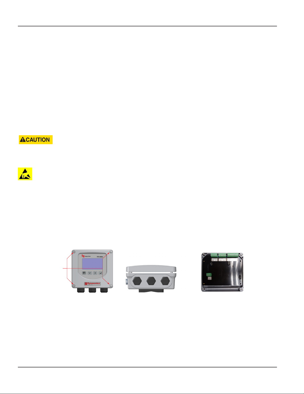
Replacement Instructions
REPLACEMENT INSTRUCTIONS
This product cannot be repaired by the user and must be replaced with an equivalent certified product. Repairs are only
allowed to be carried out by the manufacturer or its authorized agent.
Front Panel Replacement
A replacement front panel assembly with display/keypad (PN D080-1020-001) is available and includes the front cover,
display/keypad/overlay, main board, connectors and shield. A replacement front panel assembly without the display/keypad
(PN D080-1020-002) is also available. It includes the front cover, main board, connectors and shield.
The front panel is a single piece and is easily removed by unscrewing the four enclosure screws. Turn off the power before
replacing the front panel.
Main Board Replacement
Replacing the complete transmitter or the front panel as a single piece is the preferred method. However, you can replace only
the main board (PN D020-2100-005), if necessary. Instructions follow.
CONTAINS PARTS AND ASSEMBLIES SUSCEPTIBLE TO DAMAGE BY ELECTROSTATIC DISCHARGE (ESD). BEFORE PICKING
UP AN ESD-SENSITIVE ELECTRONIC COMPONENT, DISCHARGE YOURSELF BY TOUCHING A GROUNDED BARE METAL
SURFACE OR APPROVED ANTI-STATIC MAT.
OBSERVE PRECAUTIONS FOR HANDLING ELECTROSTATIC-SENSITIVE DEVICES.
Tools Required
• A Philips #2 screwdriver
• A flat blade screwdriver
• Tweezers for electronics
• A workbench that prevents ESD damage to the electronics
To remove the main board:
1. Turn o the power.
2. Completely loosen and remove the four captive screws on the transmitter cover. Lift and remove the cover and place it
face down on a stable work surface.
Unscrew
Captive Screws
Figure 30: Captive cover screws Figure 31: Remove cover from base Figure 32: Lay cover face down
3. Remove the terminal blocks from the board.
4. Remove the four screws holding the shield and main board in place. The main board will remain in place.
5. Remove the PCB shield from the board and set it aside.
Page 36 April 2019TTM-UM-02537-EN-04
Page 37

Replacement Instructions
Figure 33: PCB shield removed
6. On the left side of the board at J501, gently slide the keypad ribbon cable retainer away from the center of the board.
Gently remove the keypad ribbon cable from the main board.
Figure 34: PCB sheild removed
7. Pull the main board away from the front panel. There is a connector with long pins that connects the main board to the
display board, so you will feel some friction but it should not require a lot of eort. Do NOT remove the display board as
doing so will damage the display.
To install the main board:
1. While holding the main board, insert the keypad ribbon cable into the keypad ribbon cable connector at J501. You may
need to use tweezers for electronics to insert the ribbon cable. Slide the cable retainer toward the center of the board to
secure the keypad ribbon cable.
2. Align the pins on the display board to the holes on the main board and slide on the main board.
3. Re-install the shield and the four screws.
4. Reconnect the wiring to the terminal blocks.
5. Close the enclosure and tighten the four screws.
Page 37 April 2019 TTM-UM-02537-EN-04
Page 38

Specications
SPECIFICATIONS
System
Liquid Types Water containing small amounts of suspended solids or gas bubbles
Velocity Range 0.1…40 ft/s (0.03…12 m/s) bidirectional
Flow Accuracy
Repeatability ±0.2% of reading
Transducer Type Clamp-on ultrasonics
Certifications
DTTR/DTTN
DTTC
Easy Rail (DTTJ, DTTK)
Remote mount transmitter and
integral mount transmitter with
transducers
Transmitter
±1% of reading or ±0.01 FPS (0.003 MPS), whichever is greater
DTTC 3/4 in. and smaller are accurate to ± 1% full scale
General Safety (option): FM Class 3810:2018, ANSI/ISA 61010-1:2012, ANSI/IEC 60529:2004,
CAN/CSA-C22.2 No. 61010-1:2012, CSA C22.2 No. 60529:2005
CE: EMC Directive 2014/30/EU
Power
Requirements
Display
Enclosure IP66; polycarbonate
Ambient
Temperature
Units of
Measure
Mounting Wall or pipe remote mount or integral mount; Enclosure can be rotated in 90° increments
Inputs Digital input 5…30V DC, externally or internally sourced; totalizer reset or alarm unlatch
Outputs
Networks
Configuration
Port
Alarms Buffer previous alarms, warnings or errors
Languages English, French, German and Spanish selectable
Security Four levels: Read-only, Operator, Service and Admin; 6-digit passcode number; selectable auto logout
DC Class II power supply is required; 9…28V DC @ 5 W maximum
Protection Reverse polarity and transient suppression
Keypad 4-button navigation, membrane keypad with domed tactile feedback
Resolution 128 × 64 pixel LED backlit graphical display; adjustable brightness and timeout
Operational ambient With display: –4…140° F (–20…60° C); without display: –40…158° F (–40…70° C)
Storage –40…176° F (–40…80° C)
Velocity feet/second, meters/second
Totals
Flow rate
Pulse / Frequency /
Digital /
Analog Output 0…20 mA and 4…20 mA drive up to 800 Ohms; minimum 16-bit resolution, isolated
EIA-485 with
selectable protocols
Endpoints Connectivity to AquaCUE or BEACON cellular endpoints
USB, Type mini-B
US Gallons, Million Gallons, Imperial Gallons, Million Imperial Gallons, Acre-Feet, Barrels, Liters, Hectoliters,
Cubic Meters, Cubic Feet
Acre Feet/Day, Liters/Second, Liters/Minute, Liters/Hour, Cubic Meters/Second, Cubic Meters/Minute, Cubic
Meters/Hour, Cubic Feet/Minute, Cubic Feet/Minute, Cubic Feet/Hour, Gallons/Second, Gallons/Minute, Gallons/
Hour, Million Gallons/Day, Imperial Gallons/Second, Imperial Gallons/Minute, Imperial Gallons/Hour, Barrel/
Minute, Million Imperial Gallons/Day, Barrel/Day
Two outputs, each selectable as frequency, pulse, forward/reverse flow or alarm output; isolated open collector,
5…30V DC, externally or internally sourced with pullup resistor
Digital alarm output: configurable high or low
Frequency output: 0.5 Hz…16 kHz maximum
Pulse (totalizer) output: 5 kHz maximum output open collector, pulse width 5…500 ms programmable
Modbus RTU, baud rates 9600, 19200, 38400, 57600, 76800, 115200
BACnet MS/TP, baud rates 9600, 19200, 38400, 57600, 76800, 115200
Page 38 April 2019TTM-UM-02537-EN-04
Page 39
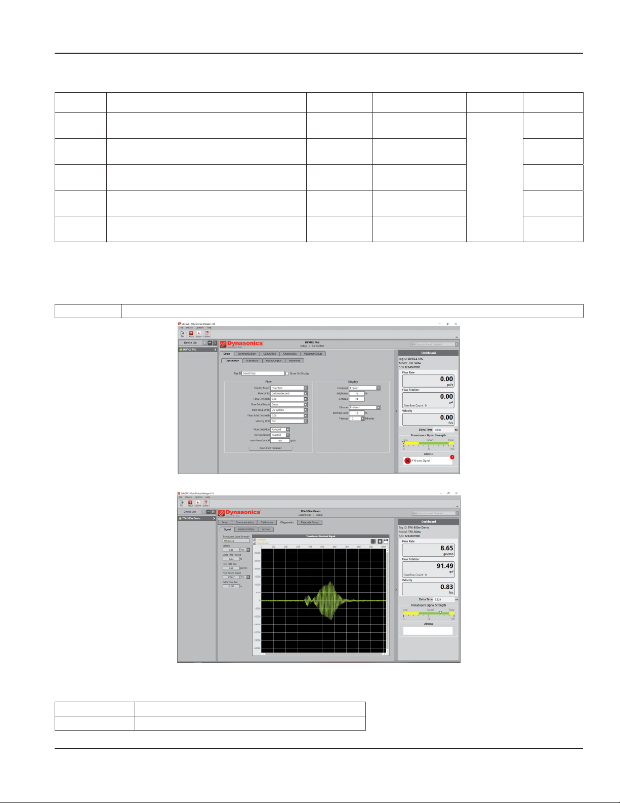
Transducers
Specications
Model Construction Cable Length Pipe/Tubing Sizes
DTTC
DTTR
DTTN
DTTN
Submersible
Easy Rail
(DTTJ/K)
* DTTC integral mount temperature is limited by the transmitter temperature rating
CPVC, Ultem, Nylon cord grip
Polyethylene cable jacket; –40…194° F (–40…90° C)*
PBT glass filled, Ultem®, Nylon cord grip
PVC cable jacket; –40…250° F (–40…121° C)
CPVC, Ultem, Nylon cord grip
Polyethylene cable jacket; –40…194° F (–40…90° C)
CPVC, Ultem, Nylon cord grip
Polyethylene cable jacket; –40…194° F (–40…90° C)
PBT glass filled, Ultem®, Nylon cord grip
PVC cable jacket; –40…250° F (–40…121° C)
100 ft (90 m) max. 0.5…2 in. (12…50 mm)
300 ft (90 m) max. 2…10 in. (DN50…DN250) NEMA 6/IP67
300 ft (90 m) max. 2…10 in. (DN50…DN250) NEMA 6/IP67
300 ft (90 m) max. 2…10 in. (DN50…DN250) NEMA 6P/IP68
100 ft (30 m) max.
2…6 in. (DN50…DN150)
2…10 in. (DN50…DN250)
Pipe/Tubing
Materials
Carbon steel,
stainless steel,
copper and
plastic
Protection
NEMA 6/IP67
NEMA 6/IP67
Conguration Software
The flow meter can be programmed and configured with the SoloCUE Flow Device Manager software. The software also has
troubleshooting tools for diagnosing and correcting installation problems.
SoloCUE Used to configure and troubleshoot flow meter. Software is compatible with Windows® 7 SP1 or newer
Figure 35: SoloCUE setup screen
Figure 6: SoloCUE diagnostics screeen
Additional Parts Required for Configuration
Part Number Description
RC820648 USB Type A to mini B software cable (shielded to minimize noise)
Page 39 April 2019 TTM-UM-02537-EN-04
Page 40
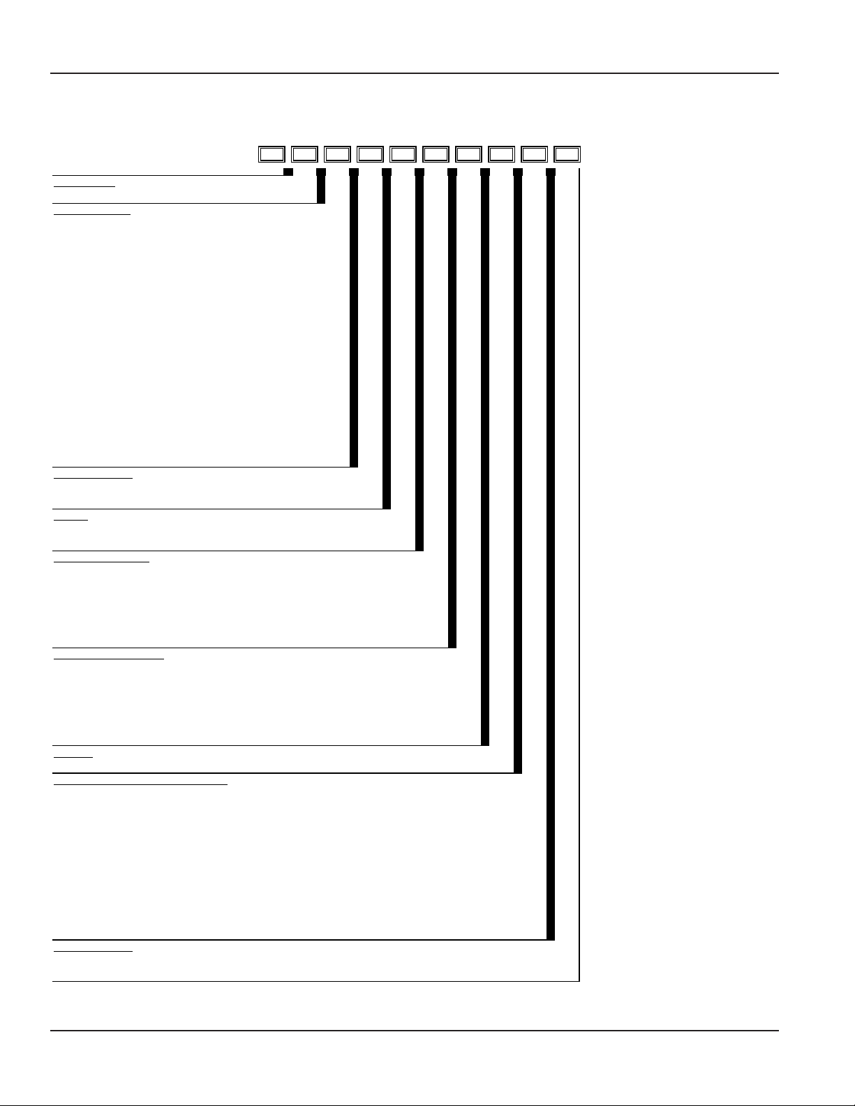
- - - - - -
- -
CONDUIT TYPE AND LENGTH
1
Part Number Construction
PART NUMBER CONSTRUCTION
DW-G
Transit Time: Pipes ≤ 2 in. (50 mm)
CERTIFICATION
General Area, CE G
TRANSDUCER TYPE
1/2 in. ANSI pipe CA
3/4 in. ANSI pipe CB
1 in. ANSI pipe CC
1-1/4 in. ANSI pipe CD
1-1/2 in. ANSI pipe CE
2 in. ANSI pipe CF
1/2 in. Copper Tube CG
3/4 in. Copper Tube CH
1 in. Copper Tube CT
1-1/4 in. Copper Tube CJ
1-1/2 in. Copper Tube CK
2 in. Copper Tube CL
1/2 in. Stainless Steel Tube CM
3/4 in. Stainless Steel Tube CN
1 in. Stainless Steel Tube CP
1-1/4 in. Stainless Steel T ube CQ
1-1/2 in. Stainless Steel T ube CR
2 in. Stainless Steel Tube CS
TRANSMITTER TYPE
24V DC | Meter Mounted E
24V DC | Remoted Mounted
F
DISPLAY
Standard S
No display with keypad W
REMOTE CABLE LENGTH
None (Meter Mounted) WW
15 ft (4.57 m) AC
30 ft (9.14 m) AF
50 ft (15.24 m) AK
75 ft (22.86 m) AR
100 ft (30.48 m) BW
S
None WW
15 ft (4.57 m) AC
30 ft (9.14 m) AF
50 ft (15.24 m) AK
75 ft (22.86 m) AR
100 ft (30.48 m) BW
RESERVED
Standard S
UNITS OF MEASURE: TOTALIZER / FLOW RATE
Gallons/gallons per minute G
Gallons/cubic feet per minute B
Cubic Meters/cubic meters per minute T
Cubic Meters/cubic meters per hour H
Cubic Feet/gallons per minute F
Cubic Feet/cubic feet per minute J
Liters/liters per second N
Liters/liters per minute P
Liters/liters per hour Q
Million Gallons/gallons per minute M
Acre Feet/gallons per minute A
TESTING & TAGGING
Factory Calibrated F
Factory Calibrated/ID Tag S
1
Conduit length must be less than or equal to cable length. Submersible Conduit limited to 100 ft (30 m).
Page 40 April 2019TTM-UM-02537-EN-04
Page 41

-
- -
- - - -
- -
CONDUIT AND CABLE LENGTH
1
Part Number Construction
DW
G
F
Transit Time: Pipes ≥ 2 in. (50 mm)
CERTIFICATIONS
General Area, CE G
TRANSDUCER TYPE
Easy Rail | 2 … 6 in. (50…150 mm) Pipes
Easy Rail | 2 … 10 in. (50… 300 mm) Pipes
DTTN | Medium Pipes
DTTN (Submersible) | Medium Pipes
DTTR | Medium Pipes
JZ
KZ
NZ
WZ
RZ
TRANSMITTER TYPE
24V DC Remote Mounted F
DISPLAY
Standard S
No display with keypad W
REMOTE CABLE LENGTH
15 ft (4.57 m) AC
30 ft (9.14 m) AF
50 ft (15.24 m) AK
75 ft (22.86 m) AR
100 ft (30.48 m) BW
150 ft (45.72 m) BK
200 ft (60.96 m) DW
250 ft (76.20 m) DK
300 ft (91.44 m) EW
S
None WW
15 ft (4.57 m) AC
30 ft (9.14 m) AF
50 ft (15.24 m) AK
75 ft (22.86 m) AR
100 ft (30.48 m) BW
150 ft (45.72 m) BK
200 ft (60.96 m) DW
250 ft (76.20 m) DK
300 ft (91.44 m) EW
RESERVED
Standard S
UNITS OF MEASURE: TOTALIZER / FLOW RATE
Gallons/gallons per minute
Gallons/cubic feet per minute
Cubic Meters/cubic meters per minute
Cubic Meters/cubic meters per hour
Cubic Feet/gallons per minute
Cubic Feet/cubic feet per minute
Liters/liters per second N
Liters/liters per minute P
Liters/liters per hour Q
Million Gallons/gallons per minute M
Acre Feet/gallons per minute A
TESTING & TAGGING
Factory Calibrated
Factory Calibrated/ID Tag
1
Conduit length must be less than or equal to cable length. Submersible Conduit limited to 100 ft (30 m).
G
B
T
H
F
J
F
S
Page 41 April 2019 TTM-UM-02537-EN-04
Page 42

North American Pipe Schedules
NORTH AMERICAN PIPE SCHEDULES
Steel, Stainless Steel, PVC Pipe, Standard Classes
NPS
in.
1 1.315
1.25 1.660 1.278 0.191 1.278 0.191 1.160 0.250
1.5 1.900 1.500 0.200 1.500 0.200 1.338 0.281
2 2.375 1.939 0.218 1.939 0.218 1.687 0.344
2.5 2.875 2.323 0.276 2.323 0.276 2.125 0.375
3 3.500 2.900 0.300 2.900 0.300 2.624 0.438
3.5 4.000
4 4.500 3.826 0.337 3.826 0.337 3.624 0.438 3.438 0.531
5 5.563 4.813 0.375 4.813 0.375 4.563 0.500 4.313 0.625
6 6.625 5.761 0.432 5.761 0.432 5.501 0.562 5.187 0.719
8 8.625 7.813 0.406 7.625 0.500 7.625 0.500 7.437 0.594 7.178 0.719 6.183 1.221
10 10.75 9.750 0.500 9.75 0.500 9.562 0.594 9.312 0.719 9.062 0.844 8.500 1.125
OD
in.
SCH 60 X STG. SCH 80 SCH 100 SCH 120/140 SCH 180
ID
in.
—
—
Wall
in.
ID
in.
0.957 0.179 0.957 0.179
3.364 0.318 3.364 0.318
Wall
in.
Table 1: Steel, stainless steel, PVC pipe, standard classes
ID
in.
Wall
in.
ID
in.
Wall
in.
— —
—
ID
in.
Wall
in.
— —
ID
in.
0.815 0.250
Steel, Stainless Steel, PVC Pipe, Standard Classes (continued)
SCH 10
(Lt Wall)
ID
in.
Wall
in.
SCH 20 SCH 30 STD SCH 40
ID
in.
Wall
in.
— —
— —
ID
in.
Wall
in.
ID
in.
1.049
3.548 — 3.548 0.226
Wall
in.
—
ID
in.
1.049 0.133
ID
in.
SCH 5
Wall
in.
NPS
in.
1 1.315 1.185 0.065 1.097 0.109
1.25 1.660 1.53 0.065 1.442 0.109 1.380 1.380 0.140
1.5 1.900 1.77 0.065 1.682 0.109 1.610 1.610 0.145
2 2.375 2.245 0.065 2.157 0.109 2.067 2.067 0.154
2.5 2.875 2.709 0.083 2.635 0.120 2.469 2.469 0.203
3 3.500 3.334 0.083 3.260 0.120 3.068 3.068 0.216
3.5 4.000 3.834 0.083 3.760 0.120
4 4.500 4.334 0.083 4.260 0.120 4.026 0.237 4.026 0.237
5 5.563 5.345 0.109 5.295 0.134 5.047 0.258 5.047 0.258
6 6.625 6.407 0.109 6.357 0.134 6.065 0.280 6.065 0.280
8 8.625 8.407 0.109 8.329 0.148 8.125 0.250 8.071 0.277 7.981 0.322 7.981 0.322
10 10.75 10.482 0.134 10.42 0.165 10.25 0.250 10.13 0.310 10.02 0.365 10.02 0.365
OD
in.
Wall
in.
Wall
in.
Table 2: Steel, stainless steel, PVC pipe, standard classes (continued)
Page 42 April 2019TTM-UM-02537-EN-04
Page 43

Copper Tubing, Copper and Brass Pipe, Aluminum
North American Pipe Schedules
Nominal
Diameter
0.5
0.6250
0.75
1
1.25
1.5.
2
2.5
3
Copper Tubing
in.
in.
K L M K L M
OD 0.625 0.625 0.625 0.840
ID 0.527 0.545 0.569 0.625 ID 3.385 3.425 3.459 3.500
OD 0.750 0.750 0.750
Wall 0.049 0.042 0.030 Wall 0.134 0.110 0.095 0.095 0.250
ID 0.652 0.666 0.690 ID 3 857 3.905 3.935 3.935 4.000
OD 0.875 0.875 0.875 1.050
Wall 0.065 0.045 0.032 0.114 Wall 0.250
ID 0.745 0.785 0.811 0.822 ID 4.500
OD 1.125 1.125 1.125 1.315
Wall 0.065 0.050 0.035 0.127 Wall 0.160 0.125 0.109 0.250 0.063
ID 0.995 1.025 1.055 1.062 ID 4.805 4.875 4.907 5.063 4.874
OD 1.375 1.375 1.375 1.660
Wall 0.065 0.055 0.042 0.146 Wall 0.192 0.140 0.122 0.250 0.063
ID 1.245 1.265 1.291 1.368 ID 5.741 5.845 5.881 6.125 5.874
OD 1.625 1.625 1.625 1.900
Wall 0.072 0.060 0.049 0.150 Wall 0.282 0.078
ID 1.481 1.505 1.527 1.600 ID 7.062 6.844
OD 2.125 2.125 2.125 2.375
Wall 0.083 0.070 0.058 0.157 Wall 0,271 0.200 0.170 0.313 0.094
ID 1.959 1.985 2.009 2.062 ID 7.583 7.725 7.785 8.000 7.812
OD 2.625 2.625 2.625 2.875 2.500
Wall 0.095 0.080 0.065 0.188 0.050 Wall 0.338 0.250 0.212 0.094 —
ID 2.435 2.465 2.495 2.500 2.400 ID 9.449 9.625 9.701 9.812 —
OD 3.125 3.125 3.125 3.500 3.000
Wall 0.109 0.090 0.072 0.219 0.050
ID 2.907 2.945 2.981 3.062 2.900
Type Type
Copper
& Brass
Pipe
in.
— — 4
Table 3: Copper tubing, copper and brass pipe, aluminum
Alum.
in.
— 3-1/2
— 4-1/2
— 5
— 6
— 7
— 8
Nominal
Diameter
in.
OD 3.625 3.625 3.625 4.000
OD 4.125 4.125 4.125 4.500 4.000
OD
OD 5.125 5.125 5.125 5.563 5.000
OD 6.125 6.125 6.125 6.625 6.000
OD
OD 8.125 8.125 8.125 8.625 8 000
OD 10.125 10.125 10.125 10 000 —
10
Copper Tubing
in.
— — — —
— — —
Copper
& Brass
Pipe
in.
7.625 7.000
Alum.
in.
—Wall 0.049 0.040 0.028 0.108 Wall 0.120 0.100 0.083 0.250
5.000
Page 43 April 2019 TTM-UM-02537-EN-04
Page 44

Transit Time Ultrasonic Flow Meters, TFX-500w Clamp-On Meter
Cast Iron Pipe, Standard Classes, 3…10 inch
10
Size
in.
Class
in.
A B C D E F G H
OD 3.80 3.96 3.96 3.96
3
— — — —Wall 0.39 0.42 0.45 0.48
ID 3.02 3.12 3.06 3.00
OD 4.80 5.00 5.00 5.00
4
— — — —Wall 0.42 0.45 0.48 0.52
ID 3.96 4.10 4.04 3.96
OD 6.90 7.10 7.10 7.10 7.22 7.22 7.38 7.38
6
Wall 0.44 0.48 0.51 0.55 0.58 0.61 0.65 0.69
ID 6.02 6.14 6.08 6.00 6.06 6.00 6.08 6.00
OD 9.05 9.05 9.30 9.30 9.42 9.42 9.60 9.60
8
Wall 0.46 0.51 0.56 0.60 0.66 0.66 0.75 0.80
ID 8.13 8.03 8.18 8.10 8.10 8.10 8.10 8.00
OD 11.10 11.10 11.40 11.40 11.60 11.60 11.84 11.84
Wail 0.50 0.57 0.62 0.68 0.74 0.80 0.86 0.92
ID 10.10 9.96 10.16 10.04 10.12 10.00 10.12 10.00
Table 4: Cast iron pipe, standard classes, 3…10 inch
Control. Manage. Optimize.
Dynasonics, AquaCUE and SoloCUE are registered trademarks of Badger Meter, Inc. Other trademarks appearing in this document are the property of their respective entities. Due
to continuous research, product improvements and enhancements, Badger Meter reserves the right to change product or system specications without notice, except to the extent
an outstanding contractual obligation exists. © 2019 Badger Meter, Inc. All rights reserved.
www.badgermeter.com
The Americas | Badger Meter | 4545 West Brown Deer Rd | PO Box 245036 | Milwaukee, WI 53224-9536 | 800-876-3837 | 414-355-0400
México | Badger Meter de las Americas, S.A. de C.V. | Pedro Luis Ogazón N°32 | Esq. Angelina N°24 | Colonia Guadalupe Inn | CP 01050 | México, DF | México | +52-55-5662-0882
Europe, Eastern Europe Branch Oce (for Poland, Latvia, Lithuania, Estonia, Ukraine, Belarus) | Badger Meter Europe | ul. Korfantego 6 | 44-193 Knurów | Poland | +48-32-236-8787
Europe, Middle East and Africa | Badger Meter Europa GmbH | Nurtinger Str 76 | 72639 Neuen | Germany | +49-7025-9208-0
Europe, Middle East Branch Oce | Badger Meter Europe | PO Box 341442 | Dubai Silicon Oasis, Head Quarter Building, Wing C, Oce #C209 | Dubai / UAE | +971-4-371 2503
Slovakia | Badger Meter Slovakia s.r.o. | Racianska 109/B | 831 02 Bratislava, Slovakia | +421-2-44 63 83 01
Asia Pacic | Badger Meter | 80 Marine Parade Rd | 21-06 Parkway Parade | Singapore 449269 | +65-63464836
Switzerland | Badger Meter Swiss AG | Mittelholzerstrasse 8 | 3006 Bern | Switzerland | +41-31-932 01 11
 Loading...