

Page 1
Transit Time Ultrasonic Flow Meters
TFX-5000 Meter
TTM-UM-02222-EN-10 (July 2020)
User Manual
Page 2

Transit Time Ultrasonic Flow Meters, TFX-5000 Meter
CONTENTS
Scope of This Manual . . . . . . . . . . . . . . . . . . . . . . . . . . . . . . . . . . . . . . . . . . . . . . . . . . . . . . . . . . . . . . . . . . . . 5
Typographic Conventions . . . . . . . . . . . . . . . . . . . . . . . . . . . . . . . . . . . . . . . . . . . . . . . . . . . . . . . . . . . . . .5
Unpacking and Inspection . . . . . . . . . . . . . . . . . . . . . . . . . . . . . . . . . . . . . . . . . . . . . . . . . . . . . . . . . . . . . . . . 5
Safety . . . . . . . . . . . . . . . . . . . . . . . . . . . . . . . . . . . . . . . . . . . . . . . . . . . . . . . . . . . . . . . . . . . . . . . . . . . . . .5
Terminology and Symbols . . . . . . . . . . . . . . . . . . . . . . . . . . . . . . . . . . . . . . . . . . . . . . . . . . . . . . . . . . . . . . 5
Considerations . . . . . . . . . . . . . . . . . . . . . . . . . . . . . . . . . . . . . . . . . . . . . . . . . . . . . . . . . . . . . . . . . . . . .5
Introduction. . . . . . . . . . . . . . . . . . . . . . . . . . . . . . . . . . . . . . . . . . . . . . . . . . . . . . . . . . . . . . . . . . . . . . . . . .6
Dimensions . . . . . . . . . . . . . . . . . . . . . . . . . . . . . . . . . . . . . . . . . . . . . . . . . . . . . . . . . . . . . . . . . . . . . . . . . . 6
Remote Enclosure . . . . . . . . . . . . . . . . . . . . . . . . . . . . . . . . . . . . . . . . . . . . . . . . . . . . . . . . . . . . . . . . . . . 6
Wall Mount Bracket . . . . . . . . . . . . . . . . . . . . . . . . . . . . . . . . . . . . . . . . . . . . . . . . . . . . . . . . . . . . . . . . . .7
Panel Mount Enclosure . . . . . . . . . . . . . . . . . . . . . . . . . . . . . . . . . . . . . . . . . . . . . . . . . . . . . . . . . . . . . . . .7
Operation . . . . . . . . . . . . . . . . . . . . . . . . . . . . . . . . . . . . . . . . . . . . . . . . . . . . . . . . . . . . . . . . . . . . . . . . . . .8
Keypad Operation on the Home Screen . . . . . . . . . . . . . . . . . . . . . . . . . . . . . . . . . . . . . . . . . . . . . . . . . . . . . 8
Keypad Operation in the Menu Structure . . . . . . . . . . . . . . . . . . . . . . . . . . . . . . . . . . . . . . . . . . . . . . . . . . . . 8
Selecting an Option in a Parameter Selection List . . . . . . . . . . . . . . . . . . . . . . . . . . . . . . . . . . . . . . . . . . . . . . . 9
Entering a Number . . . . . . . . . . . . . . . . . . . . . . . . . . . . . . . . . . . . . . . . . . . . . . . . . . . . . . . . . . . . . . . . . .9
Installation. . . . . . . . . . . . . . . . . . . . . . . . . . . . . . . . . . . . . . . . . . . . . . . . . . . . . . . . . . . . . . . . . . . . . . . . . .10
Overview . . . . . . . . . . . . . . . . . . . . . . . . . . . . . . . . . . . . . . . . . . . . . . . . . . . . . . . . . . . . . . . . . . . . . . . .10
Installation Considerations . . . . . . . . . . . . . . . . . . . . . . . . . . . . . . . . . . . . . . . . . . . . . . . . . . . . . . . . . . . . 10
Equipment Required . . . . . . . . . . . . . . . . . . . . . . . . . . . . . . . . . . . . . . . . . . . . . . . . . . . . . . . . . . . . . . . . 10
Installing the Transducers . . . . . . . . . . . . . . . . . . . . . . . . . . . . . . . . . . . . . . . . . . . . . . . . . . . . . . . . . . . . . 10
Installing a Meter with a Remote Transmitter and Fixed Transducers . . . . . . . . . . . . . . . . . . . . . . . . . . . . . . . . . . 11
Installing a Meter with a Remote Transmitter and Adjustable Transducers . . . . . . . . . . . . . . . . . . . . . . . . . . . . . . 12
Installing a Panel-Mount Meter. . . . . . . . . . . . . . . . . . . . . . . . . . . . . . . . . . . . . . . . . . . . . . . . . . . . . . . . . .13
Wiring the Transmitter . . . . . . . . . . . . . . . . . . . . . . . . . . . . . . . . . . . . . . . . . . . . . . . . . . . . . . . . . . . . . . . . . . 14
Torque Requirements . . . . . . . . . . . . . . . . . . . . . . . . . . . . . . . . . . . . . . . . . . . . . . . . . . . . . . . . . . . . . . . .14
Electrical Symbols . . . . . . . . . . . . . . . . . . . . . . . . . . . . . . . . . . . . . . . . . . . . . . . . . . . . . . . . . . . . . . . . . . 14
Connection Data . . . . . . . . . . . . . . . . . . . . . . . . . . . . . . . . . . . . . . . . . . . . . . . . . . . . . . . . . . . . . . . . . . . 14
Rated Conditions of Terminals . . . . . . . . . . . . . . . . . . . . . . . . . . . . . . . . . . . . . . . . . . . . . . . . . . . . . . . . . . 15
Wiring the Transducer. . . . . . . . . . . . . . . . . . . . . . . . . . . . . . . . . . . . . . . . . . . . . . . . . . . . . . . . . . . . . . . .15
Power . . . . . . . . . . . . . . . . . . . . . . . . . . . . . . . . . . . . . . . . . . . . . . . . . . . . . . . . . . . . . . . . . . . . . . . . . . 16
9…28V DC Power . . . . . . . . . . . . . . . . . . . . . . . . . . . . . . . . . . . . . . . . . . . . . . . . . . . . . . . . . . . . . . . . . . 16
20…26V AC Power. . . . . . . . . . . . . . . . . . . . . . . . . . . . . . . . . . . . . . . . . . . . . . . . . . . . . . . . . . . . . . . . . .16
Mains Power. . . . . . . . . . . . . . . . . . . . . . . . . . . . . . . . . . . . . . . . . . . . . . . . . . . . . . . . . . . . . . . . . . . . . .17
4…20 mA Output Wiring. . . . . . . . . . . . . . . . . . . . . . . . . . . . . . . . . . . . . . . . . . . . . . . . . . . . . . . . . . . . . .17
Digital Outputs Wiring . . . . . . . . . . . . . . . . . . . . . . . . . . . . . . . . . . . . . . . . . . . . . . . . . . . . . . . . . . . . . . . 18
Digital Input Wiring . . . . . . . . . . . . . . . . . . . . . . . . . . . . . . . . . . . . . . . . . . . . . . . . . . . . . . . . . . . . . . . . . 19
AquaCUE/BEACON Endpoint Wiring. . . . . . . . . . . . . . . . . . . . . . . . . . . . . . . . . . . . . . . . . . . . . . . . . . . . . . .19
Page ii July 2020TTM-UM-02222-EN-10
Page 3

User Manual
RTD Interface Wiring (Energy Models Only) . . . . . . . . . . . . . . . . . . . . . . . . . . . . . . . . . . . . . . . . . . . . . . . . . . 19
Auxiliary Output Card Wiring . . . . . . . . . . . . . . . . . . . . . . . . . . . . . . . . . . . . . . . . . . . . . . . . . . . . . . . . . . . 20
Installing the MicroSD Card . . . . . . . . . . . . . . . . . . . . . . . . . . . . . . . . . . . . . . . . . . . . . . . . . . . . . . . . . . . . 20
Connecting the USB Cable. . . . . . . . . . . . . . . . . . . . . . . . . . . . . . . . . . . . . . . . . . . . . . . . . . . . . . . . . . . . .21
Initial Meter Setup . . . . . . . . . . . . . . . . . . . . . . . . . . . . . . . . . . . . . . . . . . . . . . . . . . . . . . . . . . . . . . . . . . 21
Menu Map . . . . . . . . . . . . . . . . . . . . . . . . . . . . . . . . . . . . . . . . . . . . . . . . . . . . . . . . . . . . . . . . . . . . . . . . . .22
Parameter Descriptions by Menu . . . . . . . . . . . . . . . . . . . . . . . . . . . . . . . . . . . . . . . . . . . . . . . . . . . . . . . . . . . 23
Main Menu Structure . . . . . . . . . . . . . . . . . . . . . . . . . . . . . . . . . . . . . . . . . . . . . . . . . . . . . . . . . . . . . . . . 23
Setup > Units . . . . . . . . . . . . . . . . . . . . . . . . . . . . . . . . . . . . . . . . . . . . . . . . . . . . . . . . . . . . . . . . . . . . . 23
Setup > Meter > Pipe . . . . . . . . . . . . . . . . . . . . . . . . . . . . . . . . . . . . . . . . . . . . . . . . . . . . . . . . . . . . . . . . 26
Setup > Meter > Fluid. . . . . . . . . . . . . . . . . . . . . . . . . . . . . . . . . . . . . . . . . . . . . . . . . . . . . . . . . . . . . . . .27
Setup > Meter > Spacing. . . . . . . . . . . . . . . . . . . . . . . . . . . . . . . . . . . . . . . . . . . . . . . . . . . . . . . . . . . . . .27
Setup > Meter > Flow Setup. . . . . . . . . . . . . . . . . . . . . . . . . . . . . . . . . . . . . . . . . . . . . . . . . . . . . . . . . . . .27
Setup > Meter > Advanced . . . . . . . . . . . . . . . . . . . . . . . . . . . . . . . . . . . . . . . . . . . . . . . . . . . . . . . . . . . . 28
Setup > Meter > Calibration. . . . . . . . . . . . . . . . . . . . . . . . . . . . . . . . . . . . . . . . . . . . . . . . . . . . . . . . . . . .31
Setup > Input/Output > Current #1 (or Current #2) . . . . . . . . . . . . . . . . . . . . . . . . . . . . . . . . . . . . . . . . . . . . . 32
Setup > Inputs/Output > Output #1 (or Output #2 or Output #3) . . . . . . . . . . . . . . . . . . . . . . . . . . . . . . . . . . . . 33
Setup > Inputs/Output > Aux Output #1 (or Aux Output #2) . . . . . . . . . . . . . . . . . . . . . . . . . . . . . . . . . . . . . . . 36
Setup > Inputs/Output > Input . . . . . . . . . . . . . . . . . . . . . . . . . . . . . . . . . . . . . . . . . . . . . . . . . . . . . . . . . .37
Setup > Inputs/Output > RTD (Energy Models Only) . . . . . . . . . . . . . . . . . . . . . . . . . . . . . . . . . . . . . . . . . . . . 37
Setup > Communications . . . . . . . . . . . . . . . . . . . . . . . . . . . . . . . . . . . . . . . . . . . . . . . . . . . . . . . . . . . . . 38
Setup > Data Logging (Service Level Access) . . . . . . . . . . . . . . . . . . . . . . . . . . . . . . . . . . . . . . . . . . . . . . . . . 41
Setup > Options . . . . . . . . . . . . . . . . . . . . . . . . . . . . . . . . . . . . . . . . . . . . . . . . . . . . . . . . . . . . . . . . . . . 41
Setup > Passcode Setup > Security . . . . . . . . . . . . . . . . . . . . . . . . . . . . . . . . . . . . . . . . . . . . . . . . . . . . . . . 42
Setup > Passcode Setup > Passcode Recovery . . . . . . . . . . . . . . . . . . . . . . . . . . . . . . . . . . . . . . . . . . . . . . . . 42
Display Menu . . . . . . . . . . . . . . . . . . . . . . . . . . . . . . . . . . . . . . . . . . . . . . . . . . . . . . . . . . . . . . . . . . . . . 43
Information Menu . . . . . . . . . . . . . . . . . . . . . . . . . . . . . . . . . . . . . . . . . . . . . . . . . . . . . . . . . . . . . . . . . . 43
Diagnostics Menu . . . . . . . . . . . . . . . . . . . . . . . . . . . . . . . . . . . . . . . . . . . . . . . . . . . . . . . . . . . . . . . . . . 44
Reset Menu . . . . . . . . . . . . . . . . . . . . . . . . . . . . . . . . . . . . . . . . . . . . . . . . . . . . . . . . . . . . . . . . . . . . . . 45
Troubleshooting . . . . . . . . . . . . . . . . . . . . . . . . . . . . . . . . . . . . . . . . . . . . . . . . . . . . . . . . . . . . . . . . . . . . . . 46
Out of Specication Messages . . . . . . . . . . . . . . . . . . . . . . . . . . . . . . . . . . . . . . . . . . . . . . . . . . . . . . . . . . 46
Error Messages . . . . . . . . . . . . . . . . . . . . . . . . . . . . . . . . . . . . . . . . . . . . . . . . . . . . . . . . . . . . . . . . . . . . 46
Check Function Codes . . . . . . . . . . . . . . . . . . . . . . . . . . . . . . . . . . . . . . . . . . . . . . . . . . . . . . . . . . . . . . . 46
Warning and Alarm Message Codes. . . . . . . . . . . . . . . . . . . . . . . . . . . . . . . . . . . . . . . . . . . . . . . . . . . . . . .46
Symptoms . . . . . . . . . . . . . . . . . . . . . . . . . . . . . . . . . . . . . . . . . . . . . . . . . . . . . . . . . . . . . . . . . . . . . . . 48
Replacement Procedures . . . . . . . . . . . . . . . . . . . . . . . . . . . . . . . . . . . . . . . . . . . . . . . . . . . . . . . . . . . . . . . . 50
Replacing an AC Module . . . . . . . . . . . . . . . . . . . . . . . . . . . . . . . . . . . . . . . . . . . . . . . . . . . . . . . . . . . . . . 50
Replacing the Communication or Dry Contact Board . . . . . . . . . . . . . . . . . . . . . . . . . . . . . . . . . . . . . . . . . . . .51
Replacing the Main Board . . . . . . . . . . . . . . . . . . . . . . . . . . . . . . . . . . . . . . . . . . . . . . . . . . . . . . . . . . . . . 51
Firmware Update. . . . . . . . . . . . . . . . . . . . . . . . . . . . . . . . . . . . . . . . . . . . . . . . . . . . . . . . . . . . . . . . . . .52
Page iii July 2020 TTM-UM-02222-EN-10
Page 4

Transit Time Ultrasonic Flow Meters, TFX-5000 Meter
Specications. . . . . . . . . . . . . . . . . . . . . . . . . . . . . . . . . . . . . . . . . . . . . . . . . . . . . . . . . . . . . . . . . . . . . . . .52
System . . . . . . . . . . . . . . . . . . . . . . . . . . . . . . . . . . . . . . . . . . . . . . . . . . . . . . . . . . . . . . . . . . . . . . . . . 52
Transmitter . . . . . . . . . . . . . . . . . . . . . . . . . . . . . . . . . . . . . . . . . . . . . . . . . . . . . . . . . . . . . . . . . . . . . . 53
Transducers . . . . . . . . . . . . . . . . . . . . . . . . . . . . . . . . . . . . . . . . . . . . . . . . . . . . . . . . . . . . . . . . . . . . . . 54
RTD Kits. . . . . . . . . . . . . . . . . . . . . . . . . . . . . . . . . . . . . . . . . . . . . . . . . . . . . . . . . . . . . . . . . . . . . . . . .54
SoloCUE Flow Device Manager Software. . . . . . . . . . . . . . . . . . . . . . . . . . . . . . . . . . . . . . . . . . . . . . . . . . . .54
Part Number Construction. . . . . . . . . . . . . . . . . . . . . . . . . . . . . . . . . . . . . . . . . . . . . . . . . . . . . . . . . . . . . . . .55
TFX-5000 Flow Meters for Pipes 2 in. and Smaller . . . . . . . . . . . . . . . . . . . . . . . . . . . . . . . . . . . . . . . . . . . . . . 55
TFX-5000 Flow Meters for Pipes 2 in. and Smaller for Class I, Div 2 Hazardous Locations. . . . . . . . . . . . . . . . . . . . . .56
TFX-5000 Flow Meters for Pipes 2.5 in. and Larger . . . . . . . . . . . . . . . . . . . . . . . . . . . . . . . . . . . . . . . . . . . . . . 57
TFX-5000 Flow Meters for Pipes 2.5 in. and Larger for U.S./Canada Hazardous Locations . . . . . . . . . . . . . . . . . . . . . 58
TFX-5000 Flow Meters for Pipes Larger than 2 in. for ATEX/EICEx Hazardous Locations . . . . . . . . . . . . . . . . . . . . . . 59
TFX-5000 Energy Meters for Pipes 2 in. and Smaller. . . . . . . . . . . . . . . . . . . . . . . . . . . . . . . . . . . . . . . . . . . . .59
TFX-5000 Energy Meters for Pipes 2.5 in. and Larger . . . . . . . . . . . . . . . . . . . . . . . . . . . . . . . . . . . . . . . . . . . . 61
North American Pipe Schedules . . . . . . . . . . . . . . . . . . . . . . . . . . . . . . . . . . . . . . . . . . . . . . . . . . . . . . . . . . . . 62
Page iv July 2020TTM-UM-02222-EN-10
Page 5

Scope of This Manual
SCOPE OF THIS MANUAL
This manual is intended to help you get the TFX-5000 meter up and running quickly.
Read this manual carefully before attempting any installation or operation. Keep the manual accessible for future reference.
Typographic Conventions
• In step-by-step instructions, bold text indicates items on the screen you need to select or act upon.
Example: Click the Setup menu.
• Names of parameters, options, boxes, columns and fields are italicized.
Example: The value displays in the Status field.
• Messages and special markings are shown in quotation marks.
Example: “Error” displays in the title bar.
• In most cases, software screen text appears in the manual as it does on the screen. For example, if a word is capitalized on
the screen, it is capitalized when referred to in the manual.
UNPACKING AND INSPECTION
Upon opening the shipping container, visually inspect the product and applicable accessories for any physical damage such
as scratches, loose or broken parts, or any other sign of damage that may have occurred during shipment.
OTE: N If damage is found, request an inspection by the carrier’s agent within 48 hours of delivery and file a claim with the
carrier. A claim for equipment damage in transit is the sole responsibility of the purchaser.
SAFETY
Terminology and Symbols
Indicates a hazardous situation, which, if not avoided, will result in death or serious personal injury.
WARNING
Considerations
• The installation of the TFX-5000 meter must comply with all applicable federal, state, and local rules, regulations,
and codes.
• Do not use sharp objects when operating the device (such as using a pen to press buttons on the keypad).
• When the TFX-5000 meter is a part of a system, it is configured in a fail-safe operation so that if the transmitter signal is
compromised, the TFX-5000 meter will not cause harm to the system.
MPORTANTI
Not following instructions properly may impair safety of equipment and/or personnel.
WARNING
AFTER DEENERGIZING, DELAY 5 MINUTES BEFORE OPENING.
Indicates a hazardous situation, which, if not avoided, could result in death or serious personal injury.
Indicates a hazardous situation, which, if not avoided, could result in minor or moderate personal injury or
damage to property.
Page 5 July 2020 TTM-UM-02222-EN-10
Page 6
Introduction
INTRODUCTION
WARNING
THIS EQUIPMENT INCLUDES SOME EXTERNAL NONMETALLIC PARTS. THE USER SHALL THEREFORE ENSURE THAT
THE EQUIPMENT IS NOT INSTALLED IN A LOCATION WHERE IT MAY BE SUBJECTED TO EXTERNAL CONDITIONS SUCH
AS HIGHPRESSURE STEAM WHICH MIGHT CAUSE A BUILDUP OF ELECTROSTATIC CHARGES ON NONCONDUCTING
SURFACES. ADDITIONALLY, CLEANING OF THE EQUIPMENT SHOULD BE DONE ONLY WITH A DAMP CLOTH.
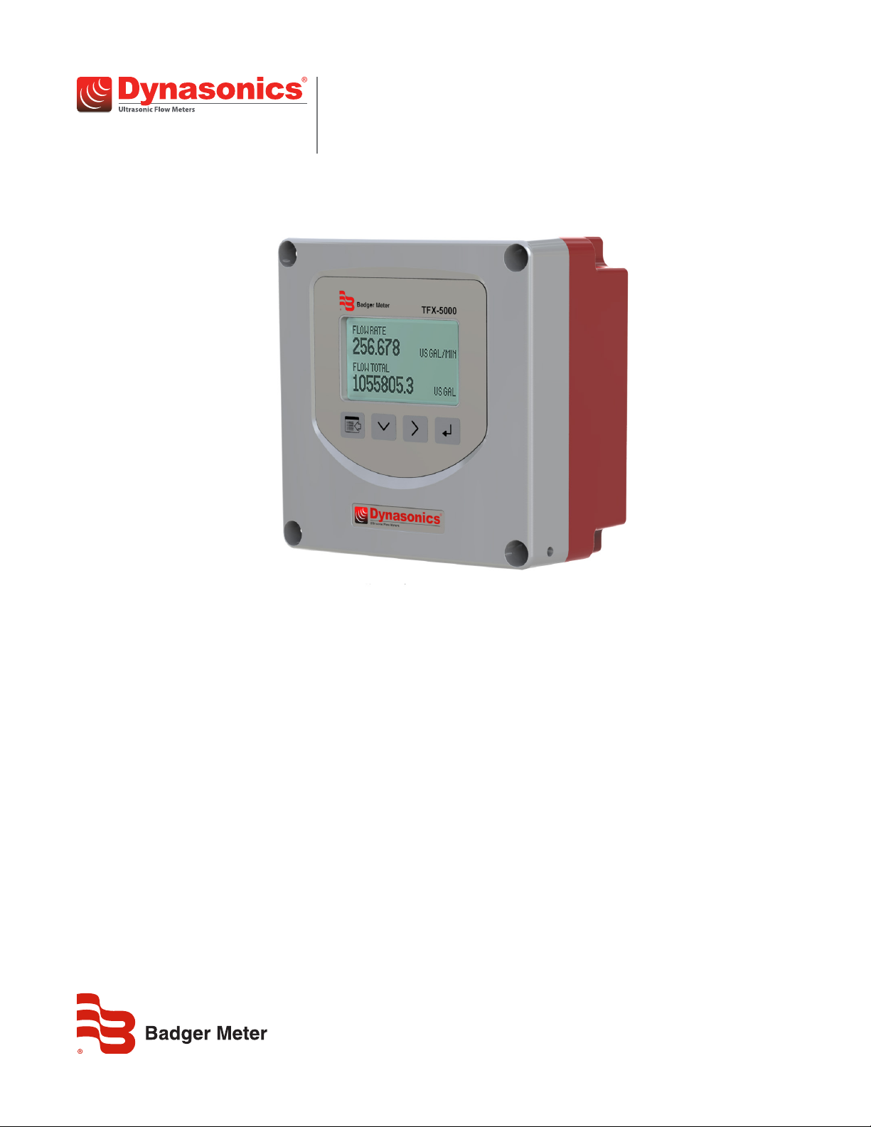
The TFX-5000 transit time meter measures volumetric flow and heating/cooling energy rates in clean liquids as well as those
with small amounts of suspended solids or aeration, such as surface water or sewage. TFX-5000 ultrasonic flow and energy
meters clamp onto the outside of pipes and do not contact the internal liquid.
The TFX-5000 meter is available in two versions:
• A flow meter for water delivery, sewage, cooling water, alcohols, chemical
• A heating/cooling energy flow meter used in conjunction with dual clamp-on RTDs for temperature measurement—ideal
for hydronic process and HVAC applications
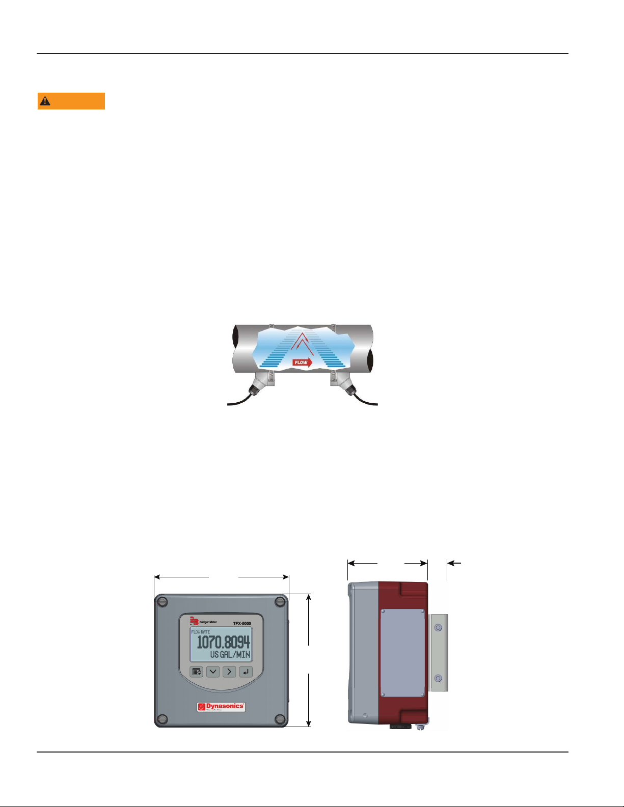
Transit time flow meters measure the time difference between the travel time of an ultrasound wave going with the fluid
flow and against the fluid flow. The time difference is used to calculate the velocity of the fluid traveling in a closed-pipe
system. The transducers used in transit time measurements operate alternately as transmitters and receivers. Transit time
measurements are bi-directional and are most effective for fluids that have low concentrations of suspended solids and are
sonically conductive.
Figure 1: Meter operation
An ultrasonic meter equipped with heat flow capabilities measures the rate and quantity of heat delivered or removed from
devices such as heat exchangers. By measuring the volumetric flow rate of the heat exchanger liquid, the temperature at the
inlet pipe and the temperature at the outlet pipe, the energy usage can be calculated.
By applying a scaling factor, this heat flow measurement can be expressed in various units (Btu, Watts, Joules, Kilowatts
and others).
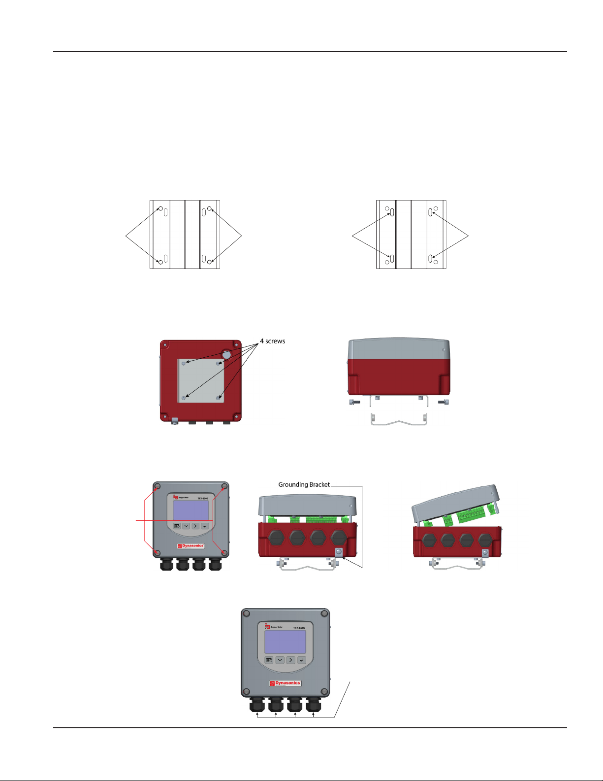
DIMENSIONS
OTE: N Installation instructions begin on page 10.
Remote Enclosure
Torque the
cover screws
to 45 in-lb.
6.50 in.
(165.10 mm)
3.63 in.
(92.20)
6.50 in.
(165.10 mm)
0.90 in.
(22.86 mm)
Figure 2: Remote mount enclosure dimensions
Page 6 July 2020TTM-UM-02222-EN-10
Page 7
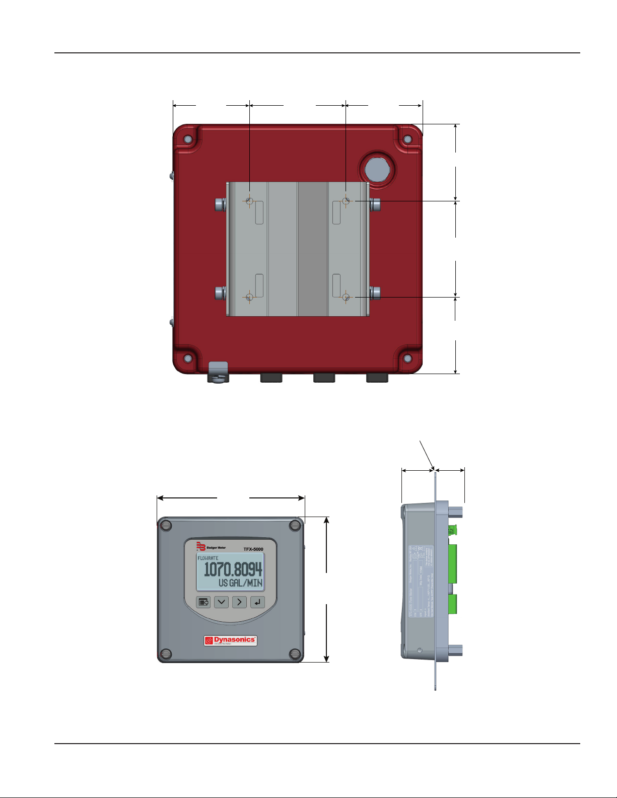
Wall Mount Bracket
Dimensions
2.00 in.
(50.80 mm)
2.50 in.
(63.50 mm)
2.00 in.
(50.80 mm)
Figure 3: Wall mount enclosure dimensions
2.00 in.
(50.80 mm)
2.50 in.
(63.50 mm)
2.00 in.
(50.80 mm)
Panel Mount Enclosure
Torque the
cover screws
to 45 in-lb.
6.50 in.
(165.10 mm)
Figure 4: Panel mount enclosure dimensions
6.50 in.
(165.10 mm)
1.38 in.
(35.05 mm)
Customer-supplied panel
1.25 in.
(31.75 mm)
Page 7 July 2020 TTM-UM-02222-EN-10
Page 8
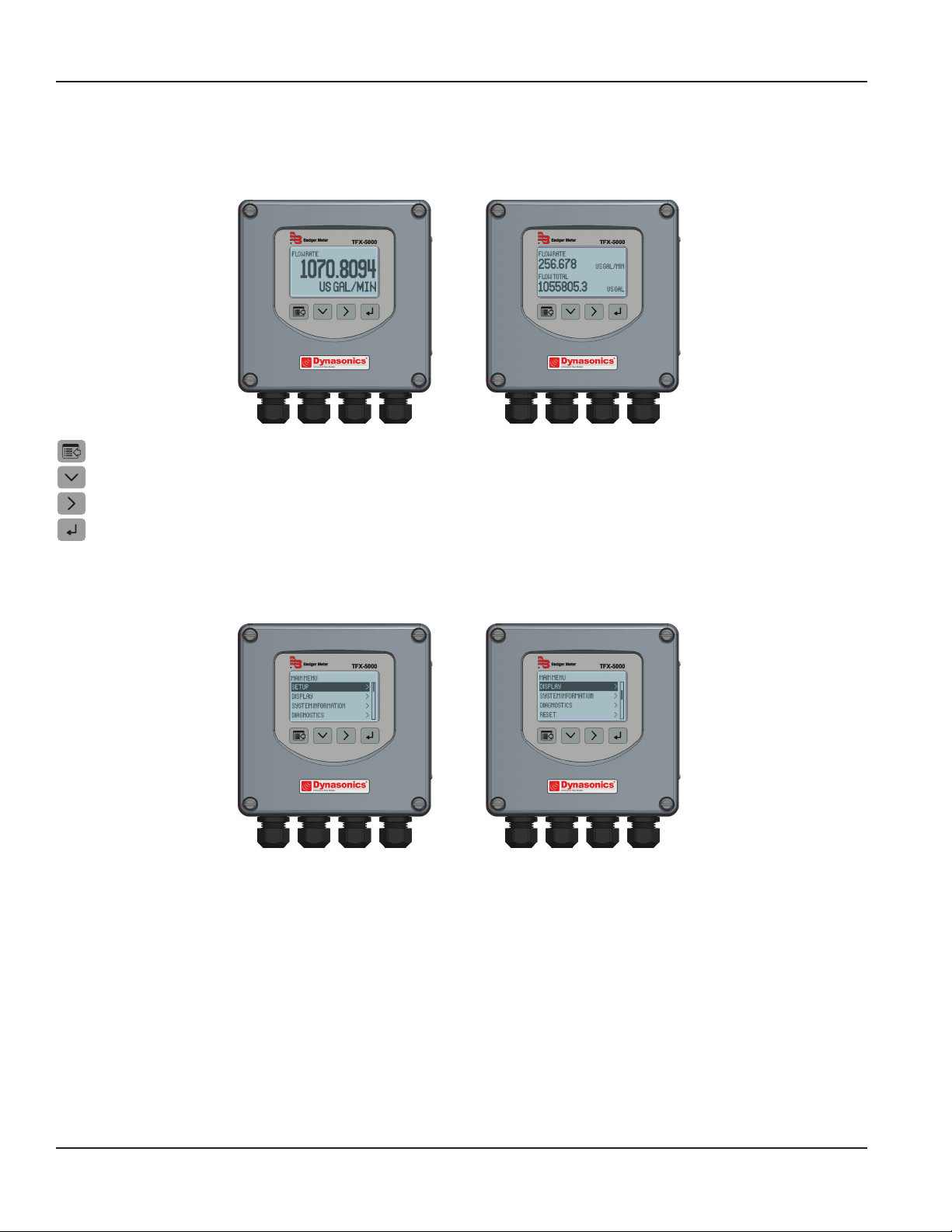
Operation
OPERATION
Keypad Operation on the Home Screen
The MENU/BACK key enters menu structure.
The DOWN ARROW key toggles between flow rate, flow total, velocity and flow rate with flow total.
The RIGHT ARROW key has no function.
The ENTER key has no function.
Keypad Operation in the Menu Structure
The cursor bar highlights the submenu or parameter that will be viewed or edited. The scroll bar on the right indicates the
relative position the cursor bar is at on the list when there are more than 4 items.
• MENU/BACK returns to parent menu (up a level). If at the Main (top level) menu, returns to the Home Screen.
• DOWN ARROW scrolls the list.
• RIGHT ARROW and ENTER have the same function in the menu structure and advance to the submenu or to
read/edit a parameter.
Page 8 July 2020TTM-UM-02222-EN-10
Page 9

Operation
Selecting an Option in a Parameter Selection List
The active option in the parameter list has a filled-in box on the left side. The scroll bar on the right indicates the relative
position the cursor bar is at on the list when there are more than 4 items.
• DOWN ARROW scrolls the list.
• ENTER selects the option and the box on the left side fills in to show the item is selected.
• MENU/BACK exits parameter editing and returns to the parent menu (up a level).
Entering a Number
The parameter name and current value is displayed in the top portion of the screen. Edit the number on the bottom right of
the screen.
• MENU/BACK exits parameter editing and returns to parent menu (up a level). The parameter remains at the value displayed
in the top portion of the screen.
• DOWN ARROW cycles through the numbers and other options.
• RIGHT ARROW moves the cursor to the right. Once it reaches the rightmost digit or a space, the cursor moves to the
leftmost digit.
• ENTER accepts the value.
Page 9 July 2020 TTM-UM-02222-EN-10
Page 10

Installation
INSTALLATION
Overview
Each of the installation steps that follow is explained in detail on page 11 through page 12 . The actual installation
procedures differ slightly, depending on whether the transducers are fixed or adjustable.
If the transducers are fixed, you will:
1. Install the transducers.
2. Install the transmitter.
3. Wire the transmitter.
4. Program the meter.
If the transducers are adjustable, you will:
1. Install the transmitter.
2. Wire the transmitter.
3. Set up the meter (select the optimum transmission mode, enter the site information, and enter the uid and
pipe properties).
4. Install the transducers.
5. Complete the meter programming.
Installation Considerations
Mount the transmitter in a location:
• Where little vibration exists.
• That is protected from corrosive fluids.
• That is within the transmitters ambient temperature limits:
–4…140° F (–20…60° C); relative humidity 0…85%, non-condensing; altitude 2000 m max.
• That is out of direct sunlight. Direct sunlight may increase transmitter temperature above the maximum limit.
• That protects the oleophobic vent from materials that may plug or seal the vent.
Equipment Required
• Screwdrivers, wide blade and tiny blade (for securing wires to the terminal blocks)
• User manual for the transducers
• Four #8 or M4 screws, if mounting the transmitter on a wall
• Stainless steel banding straps, if mounting the transmitter on a pipe
Installing the Transducers
See the user manual for your particular transducer for installation instructions.
Page 10 July 2020TTM-UM-02222-EN-10
Page 11
Wall Mounting
Wall Mounting
Installation
Installing a Meter with a Remote Transmitter and Fixed Transducers
• Locate the transmitter within the length of the transducer cables supplied or exchange the cable for one of proper length.
• See Figure 2 on page 6 for enclosure and mounting dimension details. Allow enough room for door swing, maintenance
and conduit entrances.
MPORTANTI
When routing wires to the transmitter, make sure the cables are not twisted, pinched or hanging loosely.
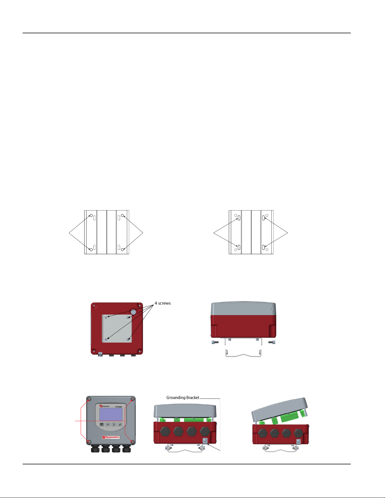
1. Install the xed transducers according to instructions in the transducer user manual.
2. Attach the mounting bracket to a wall (with 4 customer-supplied #8 or M4 screws, see “Wall Mount Bracket” on page7
for dimensions) or to a pipe (with mounting straps).
Holes for
Screws for
Figure 5: Wall mount Figure 6: Pipe Mount
Holes for
Screws for
Slots for
Straps for
Pipe Mounting
Slots for
Straps for
Pipe Mounting
3. Align the transmitter's bracket with the mounted bracket. Use a 4 mm hex tool to secure the 4 provided screws from the
sides through the mating holes. See Figure 8.
4. If necessary, you can rotate the mounting bracket in 90° increments to accommodate the nal orientation of the
transmitter. From inside the enclosure, remove the 4 screws holding the bracket. Rotate the bracket and replace the
screws. See Figure 7.
Figure 7: Rotatable adapter plate Figure 8: Secure the bracket
5. Insert a wire for earth ground under the grounding bracket (see Figure 10) and screw it down tight.
6. Partially loosen the 2 enclosure captive screws on the left side of the transmitter cover. Completely loosen the 2 screws on
the right side. Grasp and lift the cover and open it to the left. The cover remains attached and the left screws act as a hinge.
Unscrew
Captive Screws
Figure 9: Captive cover screws Figure 10: Lift cover from base Figure 11: Open cover to the left
7. Use conduit holes where cables enter the enclosure from the bottom. Use suitably certied plugs to seal any holes that are
not used for cable entry. A cable gland kit is included for inserting the transducer and power cables.
1/2 in. NPT,
1/2 in. BSPP, or
M20 Threads
Figure 12: Conduit holes
Page 11 July 2020 TTM-UM-02222-EN-10
Page 12
Wall Mounting
Wall Mounting
Installation
OTE: N Use suitably certied fittings/plugs to maintain the watertight integrity of the enclosure. Generally, the right conduit
hole (viewed from front) is used for power, the left conduit hole for transducer connections, and the center holes are
used for I/O wiring.
8. Install the wires through the gland nuts and connect the wires to the removable terminal blocks. See “Wiring the
Transmitter” on page14.
9. Wire the transducers to the transmitter.
10. Plug the wired terminal blocks into the main board.
11. Reassemble the cover. Torque the cover screws to 45 in-lb.
12. Set up the meter. See “Initial Meter Setup” on page21 for instructions.
Installing a Meter with a Remote Transmitter and Adjustable Transducers
• Locate the transmitter within the length of the transducer cables supplied or exchange the cable for one of proper length.
• Install the transducers after entering the pipe settings into the transmitter and determining the spacing and
mounting method.
• See Figure 2 on page 6 for enclosure and mounting dimension details. Allow enough room for door swing, maintenance
and conduit entrances.
MPORTANTI
When routing wires to the transmitter, make sure the cables are not twisted, pinched or hanging loosely.
1. Attach the mounting bracket to a wall (with 4 customer-supplied #8 or M4 screws, see “Wall Mount Bracket” on page7
for dimensions) or to a pipe (with mounting straps).
Holes for
Screws for
Figure 13: Wall mount Figure 14: Pipe Mount
Holes for
Screws for
Slots for
Straps for
Pipe Mounting
Slots for
Straps for
Pipe Mounting
2. Align the transmitter's bracket with the mounted bracket. Use a 4 mm hex tool to secure the 4 provided screws from the
sides through the mating holes. See Figure 16.
3. If necessary, you can rotate the mounting bracket in 90° increments to accommodate the nal orientation of the
transmitter. From inside the enclosure, remove the 4 screws holding the bracket. Rotate the bracket and replace the
screws. See Figure 15.
Figure 15: Rotatable adapter plate Figure 16: Secure the bracket
4. Insert a wire for earth ground under the grounding bracket (see Figure 18) and screw it down tight.
5. Partially loosen the 2 enclosure captive screws on the left side of the transmitter cover. Completely loosen the 2 screws on
the right side. Grasp and lift the cover and open it to the left. The cover remains attached and the left screws act as a hinge.
Page 12 July 2020TTM-UM-02222-EN-10
Unscrew
Captive Screws
Figure 17: Captive cover screws Figure 18: Lift cover from base Figure 19: Open cover to the left
Page 13
Installation
6. Use conduit holes where cables enter the enclosure from the bottom. Use suitably certied plugs to seal any holes that are
not used for cable entry. A cable gland kit is included for inserting the transducer and power cables.
1/2 in. NPT,
1/2 in. BSPP, or
M20 Threads
Figure 20: Conduit holes
OTE: N Use suitably certied fittings/plugs to maintain the watertight integrity of the enclosure. Generally, the right conduit
hole (viewed from front) is used for power, the left conduit hole for transducer connections, and the center holes are
used for I/O wiring.
7. Install the wires through the gland nuts and connect the wires to the removable terminal blocks. See “Wiring the
Transmitter” on page14.
8. Set up the meter. See “Initial Meter Setup” on page21 for instructions.
9. Install the adjustable transducers according to instructions in the transducer user manual.
10. Wire the transducers to the transmitter.
11. Plug the wired terminal blocks into the main board.
12. Reassemble the cover. Torque the cover screws to 45 in-lb.
Installing a Panel-Mount Meter
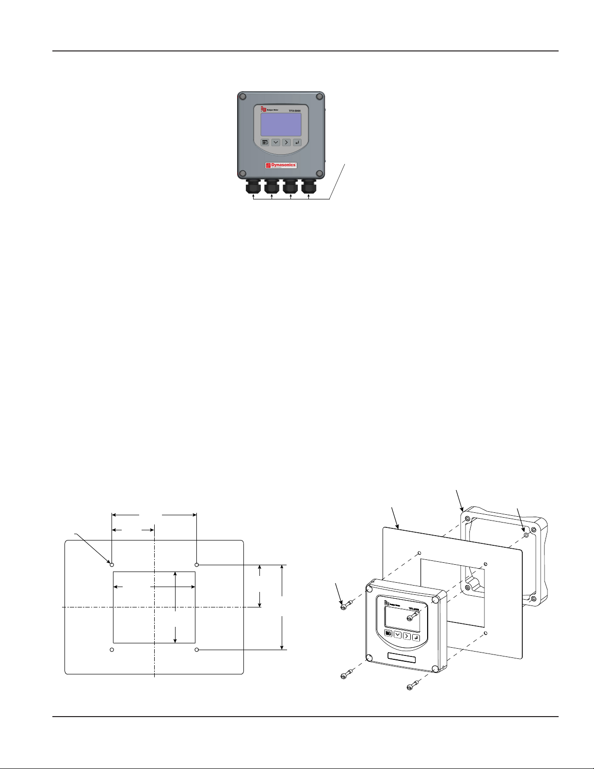
1. Measure and cut a mounting hole into the customer-supplied panel to the dimensions shown in Figure 21.
2. Remove the 4 screws and 4 O-rings holding the front of the unit to the frame.
3. Verify that the gasket is secure in the mounting bezel.
4. Guide the front of the unit through the panel cutout.
5. Insert the 4 screws through the front of the unit and the panel.
6. Apply one O-ring to each screw from the back of the panel.
7. Align the front of the unit to the frame.
8. Tighten the 4 screws and torque them to 45 in-lb.
Frame
Customer-supplied panel
Ø 0.252 in. thru
typ.
(144.78 mm)
2.85 in.
(72.93 mm)
5.50 in.
(139.70 mm)
5.70 in.
4.80 in.
(121.92 mm)
2.85 in.
(72.39 mm)
(144.78 mm)
Screws (×4)
5.70 in.
O-rings (×4)
Figure 21: Panel cutout dimensions and installation exploded view
Page 13 July 2020 TTM-UM-02222-EN-10
Page 14
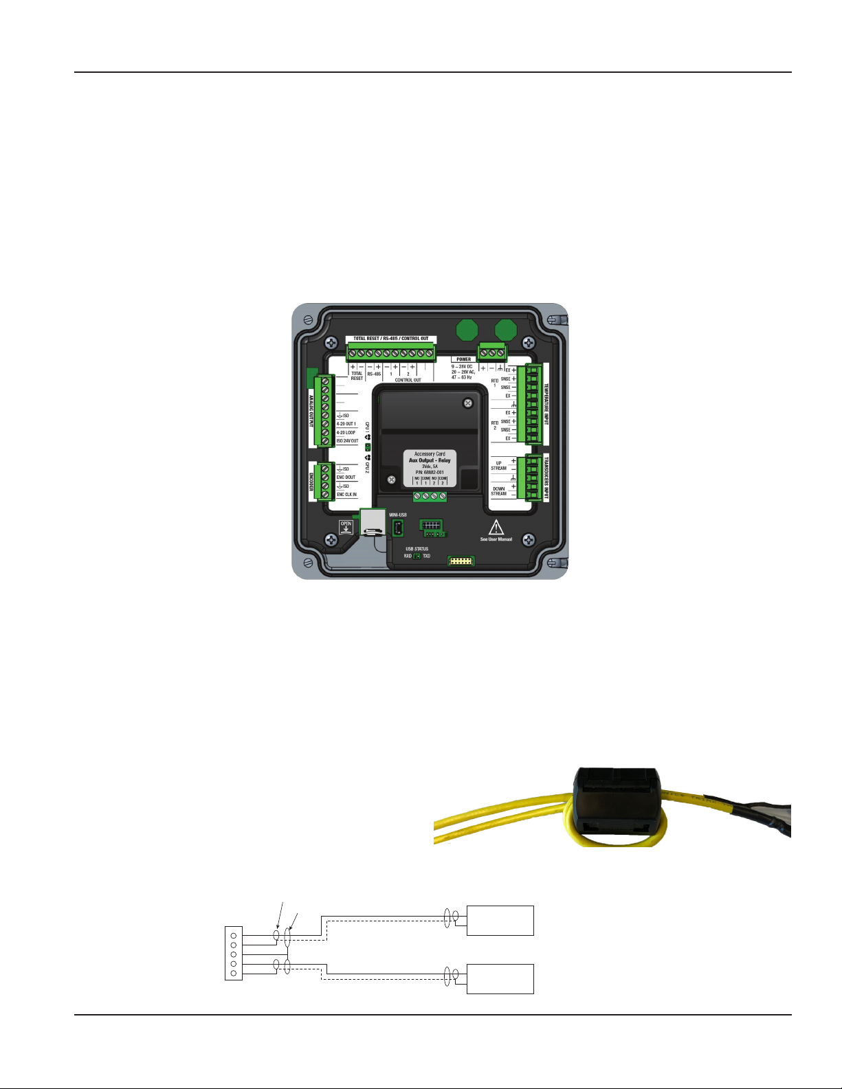
TB400
Wiring the Transmitter
WIRING THE TRANSMITTER
IMPORTANT: Select field wiring means rated for 5° C above the maximum area temperature when it is possible that the
temperature will exceed 55° C.
To access terminal strips for wiring, loosen the 4 enclosure captive screws. Grasp and lift the cover and open it to the left. The
cover remains attached and the left screws act as a hinge.
Torque Requirements
The tightening torque requirements for the screw connections of the plug-in terminals are 4.4 lb-in. (0.5 Nm) minimum to
5.3 lb-in. (0.6 Nm) maximum.
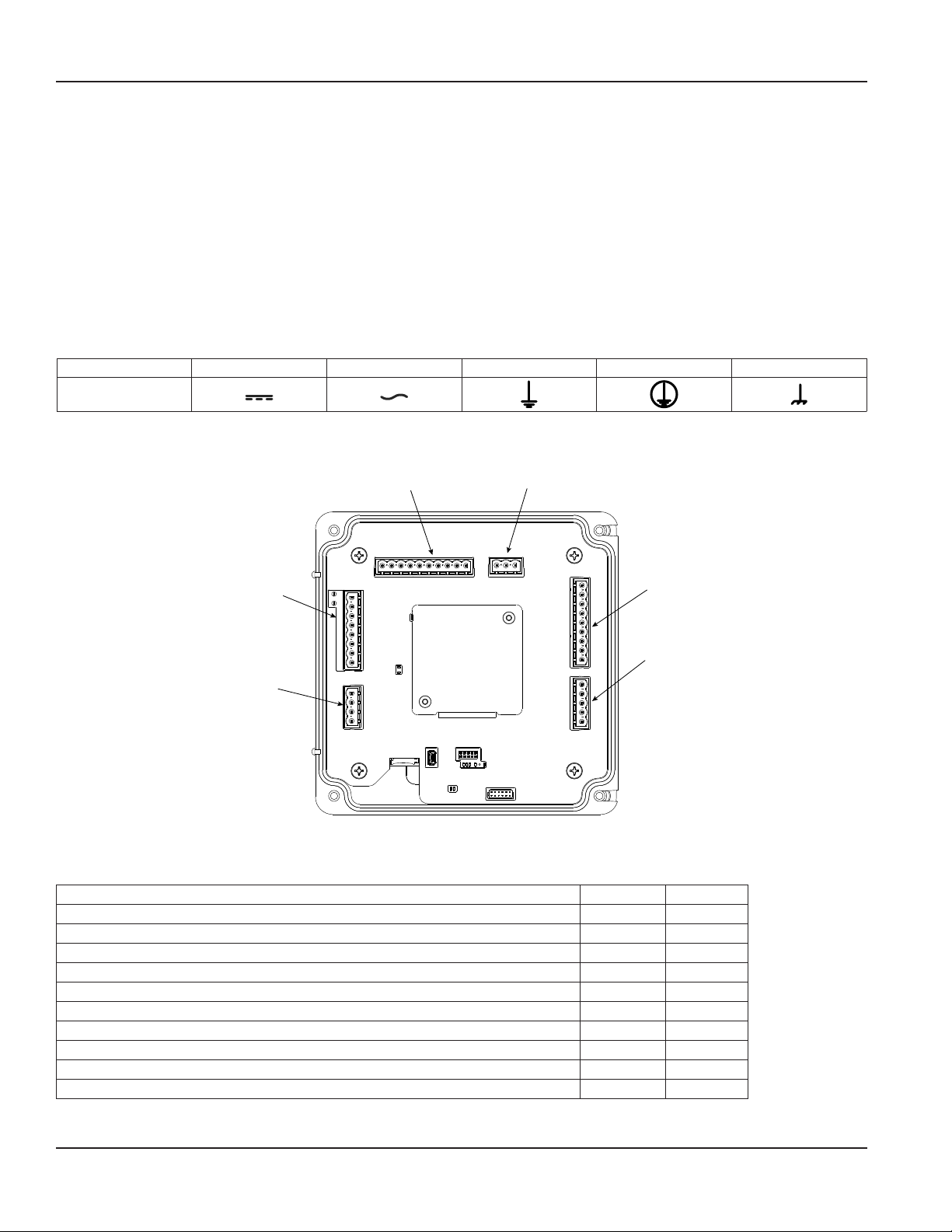
Electrical Symbols
Function Direct Current Alternating Current Earth (Ground) Protective Ground Chassis Ground
Symbol
Figure 22: Electrical symbols
TB600
Analog
Output
Connector
TB500
BEACON/
AquaCUE
Endpoint
TB700
Digital I/O
Connector
CPU
LEDs
MicroSD
Card Holder
Figure 23: Wiring connectors
USB Mini B
Connector
Accessory
Card
Power
Connector
TB900
RTD
Connector
TB300
Transducer
Connection Data
Description Minimum Maximum
Conductor cross section solid 0.2 mm² 2.5 mm²
Conductor cross section flexible 0.2 mm² 2.5 mm²
Conductor cross section flexible, with ferrule without plastic sleeve 0.25 mm² 2.5 mm²
Conductor cross section flexible, with ferrule with plastic sleeve 0.25 mm² 2.5 mm²
Conductor cross section AWG 24 12
2 conductors with same cross section, solid 0.2 mm² 1 mm²
2 conductors with same cross section, stranded 0.2 mm² 1.5 mm²
2 conductors with same cross section, stranded, ferrules without plastic sleeve 0.25 mm² 1 mm²
2 conductors with same cross section, stranded, TWIN ferrules with plastic sleeve 0.5 mm² 1.5 mm²
AWG according to UL/CUL 30 12
Page 14 July 2020TTM-UM-02222-EN-10
Page 15
Rated Conditions of Terminals
• Mains AC 85…264V AC
Wire 18…12 AWG UL AWM 1007 Type 1007
• 9…28V DC, 20…26V AC
Wire 20 AWG UL AWM 1007 Type 1007
• Transducer Cables
Badger Meter supplied cable
• Digital Outputs/Inputs, Current Output, RS485, RTD or Encoder Interface
• Wire 28…12 AWG UL AWM 1007 Type 1007
Wiring the Transducer
Wiring the Transmitter
Figure 24: Wiring connections
OTE: N Submersible transducer cables are larger diameter. Each cable requires a separate conduit hole. The standard yellow
cable and high temperature cables are small enough to use a single cable gland with a 2-hole grommet.
OTE: N Transducer cables have two wire-color combinations. For the blue and white combination, the blue wire is positive
(+) and the white wire is negative (–). For the red and black combination, the red wire is positive (+) and the black
wire is negative (–). The transducer wires are labeled to indicate which pair is upstream or downstream.
1. Guide the transducer terminations through a conduit hole in the bottom of the enclosure.
2. Secure the transducer cable with the supplied conduit nut (if exible conduit was ordered with the transducer).
3. Install the ferrite to the cable:
a. To open the ferrite, pull the fastener away from the
body of the ferrite.
b. Wrap the cable tightly around half of the ferrite and
place the cable into the groove.
c. Snap the ferrite shut.
4. The terminals within the transmitter are screw-down barrier terminals. Connect the wires at the corresponding screw
terminals in the transmitter. Observe upstream and downstream orientation and wire polarity. See Figure 25.
TB300
Red
Black
Green (2)
Red
Black
Inner Shield
Outer Shield
Upstream+
Upstream-
69039, Triax Cable
Downstream+
Downstream-
Transducer
Figure 25: Upstream/downstream transducer
Page 15 July 2020 TTM-UM-02222-EN-10
Page 16
Wiring the Transmitter
Power
Connect power to the screw terminal block in the transmitter.
• Low voltage power can use any available conduit hole in the enclosure.
• Line voltage AC power must use the right conduit hole, which is aligned with the terminal block on the AC power board.
• Use wiring practices that conform to local and national codes such as The National Electrical Code Handbook in the U.S.
ANY OTHER WIRING METHOD MAY BE UNSAFE OR CAUSE IMPROPER OPERATION OF THE TRANSMITTER.
OTE: N This transmitter requires clean electrical line power. Do not operate this transmitter on circuits with noisy
components (such as fluorescent lights, relays, compressors, or variable frequency drives). Do not use step-down
transformers from high voltage, high amperage sources. Do not to run signal wires with line power within the same
wiring tray or conduit.
9…28V DC Power
The transmitter may be operated from a 9…28V DC source, as long as the source supplies a maximum of 8 Watts of power.
Connect the DC power to 9…28V DC In, power return, and chassis ground, as in Figure 26.
OTE: N DC-powered transmitters are protected from major catastrophe with an internal 2.0 Amp slow-blow fuse. If this fuse
is blown, replace the transmitter or return it to the factory for repair.
IMPORTANT: A Class II DC power supply is required.
TB400
+
-
Switch
or
Circuit
Breaker
Chassis Ground
Figure 26: Power supply 9…28V DC
External Equipment
Power Supply (9 . . . 28V DC)
Power Supply (Return)
(Acceptable wire sizes: 28…12 AWG)
20…26V AC Power
The transmitter may be operated from a 20…26V AC source, as long as the source supplies a maximum of 8 Watts of power.
Connect the AC power to 20…26V AC In, power return, and chassis ground, as in Figure 27.
OTE: N 24V AC powered transmitters are protected from major catastrophe with an internal 2.0 Amp slow-blow fuse. If this
fuse is blown, replace the transmitter or return it to the factory for repair.
TB400 External Equipment
+
-
Switch
or
Circuit
Breaker
Chassis Ground
Figure 27: Power supply 20…28V AC
Power Supply (20 . . . 26V AC)
Power Supply (Return)
(Acceptable wire sizes: 28…12 AWG)
Page 16 July 2020TTM-UM-02222-EN-10
Page 17
Wiring the Transmitter
Mains Power
IMPORTANT: The measuring device does not have an internal circuit breaker. For compliance with IEC 61010-1, a switch in close
proximity to the transmitter is required so that the power supply line can be easily disconnected from the mains.
The transmitter may be operated from 90…250V AC, 47…63 Hz, 24VA maximum power source.
OTE: N Mains AC-powered transmitters are protected with 1A, 250V AC, 5×20 mm, slow-blow, field-replaceable fuse.
WARNING
TO PREVENT SHORTING OUT THE MAINS AC POWER, YOU MUST REPLACE THE TERMINAL BLOCK COVER ON THE AC
MODULE AFTER WIRING THE POWER.
Remove the terminal block covers before wiring and replace them after wiring:
1. Grasp the sides of the cover and gently pull it up.
2. Insert wires into the slots on the cover and screw them down to secure.
3. Align the cover in its original orientation over the terminal block and push down to connect.
TB400 External 85…264V
+
-
Factory Wired
AC-DC Power Module
(24VA max.)
Red
Black
Green
24V DC
0V DC
Chassis Ground
AC-L
AC-N
.
Connect protective earth conductor to terminal 3.
TB100
1
2
3
Switch
or
Circuit
Breaker
85 . . . 264V AC
Return
(Main power wiring must be of material
VW-1 or better.)
(Acceptable wire sizes: 18…12 AWG)
Protective
Ground
Figure 28: AC/DC power connections
4…20 mA Output Wiring
The 4…20 mA output transmits an analog current signal that is proportional to system flow rate. The 4…20 mA output can be
internally or externally powered and can span negative to positive flow rates.
Both current loops are ISOLATED from DC GND or Power.
ISO_GND
TP605
TP604
TB600
Black
Red
8
7
6
5
4
3
2
1
No Connect
No Connect
4…20 OUT 2 Current #2 Output
4…20 OUT 1 Current #1 Output
(Acceptable wire sizes: 28…12 AWG)
External Equipment
800 Ohms max.
Power Supply
Common
800 Ohms max.
NOTE: 4…20 OUT 2 available
with Energy model only.
Figure 29: Typical 4 . . . 20 mA interface using internal isolated 24V DC source
Page 17 July 2020 TTM-UM-02222-EN-10
Page 18

Wiring the Transmitter
NOTE: 4…20 OUT 2 available
with Energy model only.
Digital Outputs Wiring
NOTE: Control Output 3
available with Energy
model only.
TP605
Black
TP604
Red
8
No Connect
7
No Connect
TB600
6
5
4
3
2
1
4…20 OUT 2 Current #2 Output
4…20 OUT 1 Current #1 Output
+24V DC Source In
No Connect
(Acceptable wire sizes: 28…12 AWG)
ISO_GND
Figure 30: Typical 4 . . . 20 mA interface using external isolated 24V DC source
ISO 24V
10k
TB700
External Equipment
800 Ohms max.
Power Supply
Common
800 Ohms max.
Power
TYP 24V DC
ISO_GND
NOTE: Control Output 3
available with Energy
model only.
10 Ohms
50 mA max. Sink
ISO_GND
10 Ohms
R12
R12
(Acceptable wire sizes: 28…12 AWG)
Figure 31: Typical control out 1, 2 and 3 interface with internal pullups active
Control Output #1
Control Output #2
Control Output #3
ISO_GND
(Acceptable wire sizes: 28…12 AWG)
Figure 32: Typical control out 1, 2 and 3 interface with external pullups passive
Control Output #1
Control Output #2
Control Output #3
ISO_GND
ISO_GND
TB700
5
6
7
8
9
10
5
6
7
8
9
10
IF REQUIRED
IF REQUIRED
IF REQUIRED
IF REQUIRED
External Equipment
External Equipment
V DC (5 . . . 30V DC)
R-Pullup
R-Pullup
R-Pullup
Control Output #1
Control Output #2
Control Output #3
Control Output #1
Control Output #2
Control Output #3
Page 18 July 2020TTM-UM-02222-EN-10
Page 19
Wiring the Transmitter
RS485 Output
The RS485 feature allows up to 126 transmitters to be placed on a single three-wire cable up to 4000 feet. All transmitters are
assigned a unique numeric address that allows all of the transmitters on the cable network to be independently accessed.
Either Modbus RTU or BACnet MS/TP protocol is used to interrogate the transmitters.
Flow rate and total can be monitored over the digital communications bus.
When a USB programming cable is connected, the RS485 and frequency outputs are disabled.
Terminator Resistors
(Enabled through Parameter Setting)
60.4 Ohms
60.4 Ohms
A B
TB700
3
4
External Equipment
RS485 +
RS485 −
Figure 33: Typical RS485 interface
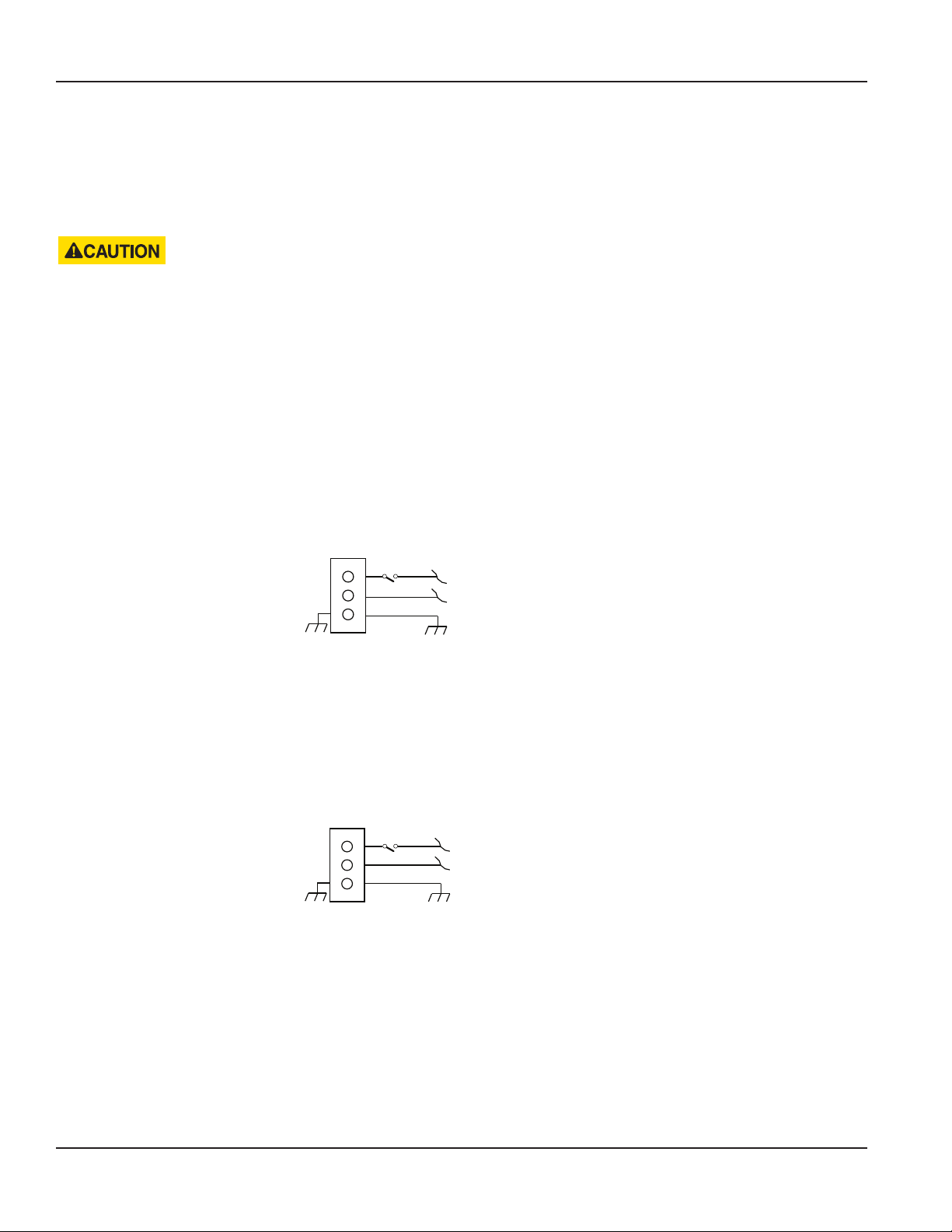
Digital Input Wiring AquaCUE/BEACON Endpoint Wiring
1
2
3
4
5
6
7
8
9
10
TB700
Reset Total +
Reset Total -
Push-button
5…30V DC
TB500
4
3
2
1
NOTE: Non-isolated
Endpoint Data Pulse Out (Green Wire)
DGND (Black Wire)
Endpoint VccClk In (Red Wire)
(Acceptable wire sizes: 28…12 AWG)
AquaCUE/BEACON
Endpoint
Figure 34: Digital input—reset totalizer Figure 35: AquaCUE/BEACON wiring
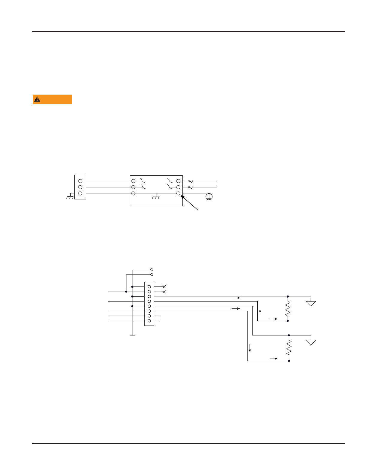
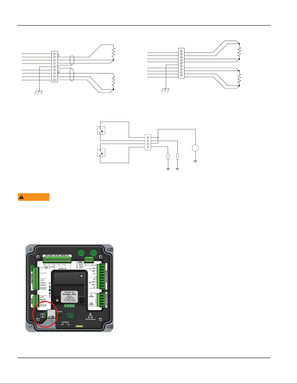
RTD Interface Wiring (Energy Models Only)
TB900
RTD1 Ex +
RTD1 Sense +
RTD1 Sense RTD1 Ex -
RTD2 Ex +
RTD2 Sense +
RTD2 Sense RTD2 Ex -
Chassis_GND
1
2
3
4
5
6
7
8
9
(Acceptable wire sizes: 28…12 AWG)
Figure 36: Two-wire RTD interface
External Equipment
Temp #1
PT100 or PT1000 RTDs
Temp #2
Page 19 July 2020 TTM-UM-02222-EN-10
Page 20
Wiring the Transmitter
(NOTE: Italicized wire colors
TB900
apply to Badger Meter PN 68996.)
RTD1 Ex +
RTD1 Sense +
RTD1 Sense RTD1 Ex -
RTD2 Ex +
RTD2 Sense +
RTD2 Sense RTD2 Ex -
Chassis_GND
1
2
3
4
5
(Black)
6
7
8
9
(Acceptable wire sizes: 28…12 AWG)
Figure 30: Three-wire RTD interface Figure 37: Four-wire RTD interface
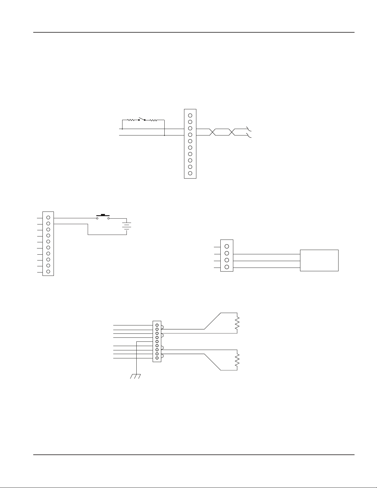
Auxiliary Output Card Wiring
AUX2 OUT
AUX1 OUT
External Equipment
(White)
(Red/Blue)
(Red)
(White)
(Red/Blue)
(Red)
44 33
Temp #1
PT100 or PT1000 RTDs
Temp #2
RTD1 Ex +
RTD1 Sense +
RTD1 Sense RTD1 Ex -
RTD2 Ex +
RTD2 Sense +
RTD2 Sense RTD2 Ex -
Chassis_GND
+V DC (30V DC, 5A max., each output)
TB100
4
3
2
1
Load 1 Load 2
Figure 38: Auxiliary output interface
TB900
1
2
3
4
5
6
7
8
9
(Acceptable wire sizes: 28…12 AWG)
Power
+
Supply
-
External Equipment
Temp #1
PT100 or PT1000 RTDs
Temp #2
Installing the MicroSD Card
WARNING
IN A HAZARDOUS LOCATION WHERE EXPLOSIVE GAS OR DUST IS PRESENT, DISCONNECT THE POWER BEFORE
OPENING THE ENCLOSURE AND INSERTING OR REMOVING THE MICROSD CARD. AFTER THE CARD IS INSERTED OR
REMOVED, CLOSE THE ENCLOSURE BEFORE REAPPLYING POWER.
1. In all locations, turn o power to the unit.
2. Remove the enclosure cover.
3. Put your nger in the groove of the tray and slide the tray downward. The tray springs open.
5. Insert the MicroSD card.
6. Slide the cover up to close.
7. Replace the enclosure cover.
Page 20 July 2020TTM-UM-02222-EN-10
Page 21

Wiring the Transmitter
Connecting the USB Cable
Use a USB cable when connecting a TFX-5000 meter to a computer with SoloCUE® Flow Device Manager software.
WARNING
DO NOT USE THE MINI USB PORT IN A HAZARDOUS LOCATION WHERE EXPLOSIVE GAS OR DUST IS PRESENT.
DO NOT OPEN THE TRANSMITTER WHILE POWERED IF WATER OR SPRAY COULD CONTACT ELECTRONICS OR INTERIOR.
1. Open the enclosure cover.
2. Connect the USB cable to the mini USB port, aligning the pins in the cable with the holes in the port.
3. Program the transmitter.
4. Remove the USB cable and close the enclosure cover.
Initial Meter Setup
You can set up the meter using the TFX-5000 keypad or the SoloCUE Flow Device Manager software. This document addresses
procedures using the TFX-5000 keypad. To use SoloCUE, see the "SoloCUE Flow Device Manager Installation Guide" available at
www.badgermeter.com.
For in-depth parameter programming, see “Parameter Descriptions by Menu” on page23.
1. Program the meter settings:
When using the keypad to set up the TFX-5000 meter to measure ow, press MENU/BACK to enter the main menu.
In the SETUP > METER menu:
a. Enter the pipe characteristics, transducer, mounting and fluid.
b. Record the calculated spacing as needed.
c. Install transducer. See the transducer user manual for instructions.
2. Check calibration:
In the SETUP > METER > CALIBRATION menu, select Field for the Factor Mode if firmware version is prior to 02.02.480. Enter
the calibration and sensor factors from the transducers into the scale factor and sensor factor value.
3. Zero the meter:
Due to different pipe characteristics, the meter must be zeroed in order to maintain accuracy. The recommended method
is to stop flow and make sure there is no flow before zeroing the meter. In situations in which that is not feasible, you may
zero the meter while the flow is steady or enter the zero manually. Based on ZERO MODE, the SET ZERO option
will be selectable.
d. If ZERO MODE is set to NO FLOW:
Check that the pipe is full of liquid and not flowing. Flow must be absolutely zero.
Securely close any valves and allow time for settling to occur.
Select SET ZERO-NO FLOW and click OK to set the new zero.
e. If ZERO MODE is set to STEADY FLOW:
Check that the pipe is full of liquid and flowing at a steady rate.
Select SET ZERO-FLOW and click OK to set the new zero.
4. Select temperature sensor (energy models only):
In the SETUP > INPUTS/OUTPUT > RTD menu, select the temperature sensor type, range and order for positive and negative
energy calculations.
5. Select units:
In the SETUP > UNITS menu, select the units and format of flow rate, total and velocity, and for energy meters the energy
rate, energy total and temperature.
6. Set up the flow settings:
In the SETUP > METER > FLOW SETUP menu, select flow direction, low and maximum flow cutoff, and minimum and
maximum signal strength.
Page 21 July 2020 TTM-UM-02222-EN-10
Page 22

Menu Map
MENU MAP
Passcode levels for write access to each menu are as follows:
NOTE:
(O) = Operator, Service or Admin
(S) = Service or Admin
(A) = Admin
If no passcode is entered, all parameters can still be read.
Press
to select
a main
menu
option.
MAIN MENU
HOME SCREEN
Flow Rate
Flow Total
Velocity
Flow Rate / Flow Total
*Energy Rate
Press
to access
this menu.
*Energy Total
*Temp #1 / Temp #2
*Energy Rate / Delta Temp
*Energy Rate / Energy Total
Time / Date
Press
to toggle
the options.
Setup Display Information
(O)
Language
Decimal
Display Tag I.D.
Brightness
Contrast
Dimmer
Dimmer Level
Timeout
Set Time
Set Date
Display Time
Display Date
Vendor
Model
P.N.
S.N.
FW Version
Cal. Date
Date Code
Tag ID
Units Meter Input/Output
(O)
Flow Units
Flow Decimals
Flow Total Mode
Flow Total Units
Flow Total Decimals
Velocity Units
Energy Rate Units
Energy Rate Decimal
Energy Total Mode
Energy Total Units
Energy Total Decimal
Temperature Units
Display Mode
Energy units only.
(S)
Transducer
Mounting
Cx Type
Pipe
Fluid
Spacing
Flow Setup
Advanced
Calibration
Aux Output #1
Aux Output #2
Optional card installed.
Readings
Signal Strength
History
Delta Time Filtered
Flow Rate Raw
Fluid Sound Speed
Delta Time Raw
Reynolds Number
Reynolds Factor
Temperature #1
Temperature #2
Delta Temperature
Total Overow Count
Energy Overow
(S)
Current #1
Current #2
Output #1
Output #2
Output #3
Input
RTD
Diagnostics
Input/Output
Status
Current #1 Output
Current #2 Output
Output #1 Status
Output #2 Status
Output #3 Status
Aux Output #1 Status
Aux Output #2 Status
Input Status
Communications
(S)
EIA-485 Type
Modbus RTU Settings
BACnet MS/TP Settings
Endpoint
BACnet/IP
Modbus TCP/IP
EtherNet/IP
Based on selected option.
Reset
(O)
Reset Flow Total
Unlatch Alarms
Hardware
Options
Card Hardware
MAC Address
Link Status
Data Logging
(S)
Log Mode
Time Interval
Parameter 1…8
Threshold
Min. Threshold
Max. Threshold
Delete Log
Available when security is enabled.
Options
(S)
Card Type
Logout
(If security is enabled
and someone is
logged in.)
System
(S)
Time
Date
Power On Time
Simulation Mode
Passcode Level
Clear History
Factory Reset
Reboot
Passcode
Setup
(A)
Security
Set Admin
Set Service
Set Operation
Logout Timeout
Passcode Recovery
Page 22 July 2020TTM-UM-02222-EN-10
Page 23

Parameter Descriptions by Menu
PARAMETER DESCRIPTIONS BY MENU
Main Menu Structure
The transmitter’s firmware has a hierarchical menu structure. See "Menu Map" on page22 for a visual path to the parameters.
The five Main Menus used in the transmitter firmware are as follows:
Menu Function
SETUP Contains all of the configuration parameters for initially programming the transmitter to measure flow
DISPLAY Configures transmitter display functions
INFORMATION Displays system information, such as the model number and firmware version
DIAGNOSTICS Displays system status and allows you to clear the history, reset to factory defaults and reboot the system
RESET Resets the flow total or unlatches alarms
The following pages define the configuration parameters located in each of the menus.
Setup > Units
Use SETUP > UNITS to define the measurement standards for the transmitter. Contains all of the configuration parameters for
setting the units and decimals for the readings and the totalizer mode. Requires operator level passcode or higher if security
is enabled.
An asterisk (*) indicates the parameter default.
Units Submenus Options/Descriptions
Select the flow rate units/interval displayed on the Home Screen. FLOW UNITS are automatically converted into
the selected option.
Option Units/Interval Option Units/Interval
Fluid BBL/D Fluid Barrels/Day (31.5 Gal) GAL/S US Gallons/Second
IBBL/D Imperial Fluid Barrels/Day (36 IG) GAL/MIN US Gallons/Minute
L/S Liters/Second GAL/H US Gallons/Hour
L/MIN Liters/Minute MG/D Million US Gallons/Day
FLOW UNITS
FLOW DECIMALS This is a numeric entry for the number of decimal places to display. Default is 2. Options are 0…7
FLOW TOTAL MODE
L/H Liters/Hour IG/S Imperial Gallons/Second
M/S Cubic Meters/Second IG/MIN Imperial Gallons/Minute
M/MIN Cubic Meters/Minute IG/H Imperial Gallons/Hour
M/H Cubic Meters/Hour MIG/D Million Imperial Gallons/Day
FT/S Cubic Feet/Minute OIL BBL/D Oil Barrels/Day (42 Gal)
FT/MIN Cubic Feet/Minute AC-FT/D Acre Feet/Day
FT/H Cubic Feet/Hour
Custom
*GROSS FLOW
FORWARD FLOW
REVERSE FLOW
NET FLOW
This selection in only available if Custom Units is enabled through SoloCUE Flow Device
Manager. Use SoloCUE to change the Custom Units.
Any ow in forward and reverse direction.
Forward ow minus reverse ow. A negative total results when reverse ow is greater than
forward ow.
Page 23 July 2020 TTM-UM-02222-EN-10
Page 24

Parameter Descriptions by Menu
Units Submenus Options/Descriptions
Select the units for the flow total displayed on the Home Screen. FLOW TOTAL UNITS are automatically converted
into the selected option:
Option Units Option Units
GAL US Gallons Fluid BBL Fluid Barrel (31.5 Gal)
MGAL Million US Gallons L Liter
FLOW TOTAL UNITS
FLOW TOTAL DECIMALS This is a numeric entry for the number of decimal places to display. Default is 0. Options are 0…7.
VELOCITY UNITS
ENERGY RATE UNITS
(Energy Units Only)
ENERGY RATE DECIMAL
(Energy Units Only)
ENERGY TOTAL MODE
(Energy Units Only)
IGAL Imperial Gallons HL Hectoliter
AC-FT Acre Foot M Cubic Meters
MIGAL Million Imperial Gallons FT Cubic Feet
Oil BBL Oil Barrels (42 Gal)
Custom
Select the units for the velocity displayed on the Home Screen.
*FT/S Feet/Second
M/S Meters/Second
Select the units for the energy rate displayed on the Home Screen. ENERGY RATE UNITS are automatically
converted into the selected option:
Option Units Option Units
BTU/H Btu/hour kJ/H Kilojoules/hour
kBTU/H Thousand Btu/hour MJ/H Mega joules/hour
MMBTU/H Million Btu/hour kCAL/H Kilocalories/hour
W Watts MCAL/H Mega calories/hour
*kW Kilowatts
MW Megawatts
This is a numeric entry for the number of decimal places to display. Default is 2. Options are 0…7.
FORWARD FLOW
REVERSE FLOW
NET FLOW Forward flow minus reverse flow. A negative total results when reverse flow is greater than
the forward flow.
*GROSS FLOW Any flow in forward and reverse direction.
Select the units for the energy total displayed on the Home Screen. ENERGY TOTAL UNITS are automatically
converted into the selected option:
This selection in only available if Custom Units is enabled through SoloCUE Flow Device
Manager. Use SoloCUE to change the Custom Units.
TON (RT)
Ton (Refrigeration)
1 Ton = 12,000 Btu/h
Option Units Option Units
ENERGY TOTAL UNITS
(Energy Units Only)
ENERGY TOTAL DECIMALS
(Energy Units Only)
TEMPERATURE UNITS
(Energy Units Only)
DISPLAY MODE
Page 24 July 2020TTM-UM-02222-EN-10
BTU British Thermal Unit kWH Kilowatt Hour
kBTU Thousand Btu MWh Megawatt Hour
MMBTU Million Btu kJ Kilo Joules
KCAL Kilo Calories MJ Mega Joules
MCAL Mega Calories TON-H Ton-hour (Refrigeration)
This is a numeric entry for the number of decimal places to display. Default is 2. Options are 0…7.
°F
°C
K
Select the parameters to display on the Home Screen. Alternatively, you can change the display from the
Home Screen by pressing the DOWN button.
*FLOW RATE ENERGY TOTAL
FLOW TOTAL TEMP #1 / TEMP #2
VELOCITY ENERGY RATE / DELTA TEMPERATURE
RATE/TOTAL ENERGY RATE / ENERGY TOTAL
ENERGY RATE TIME / DATE
Page 25

Parameter Descriptions by Menu
Setup > Meter
Contains all of the configuration parameters for setting the meter. Requires service level passcode or higher if security is
enabled. An asterisk (*) indicates the parameter default.
Meter Submenus Options/Descriptions
Select the transducer type:
UZ 2 MHZ Option UZ when ordered with the TFX-5000 meter; universal small pipe
transducers integrated in a rail
CX 2 MHZ Options CA…CT when ordered with the TFX-5000 meter; fixed size small pipe
transducers
JZ / KZ 1 MHZ Options JZ and KZ when ordered with the TFX-5000 meter; medium size pipe
TRANSDUCER
MOUNTING
Cx TYPE
NZ / RZ / WZ 1 MHZ Options NZ, WZ and RZ when ordered with the TFX-5000 meter; medium size
HZ 1 MHZ Option HZ when ordered with the TFX-5000 meter; high temperature medium
LZ / YZ 0.5 MHZ Option LZ and YZ when ordered with the TFX-5000 meter; large pipe transducers,
For mounting options, see the transducer user manual.
Z PATH
*V PATH
W PATH
DTTC TYPE is substituted for MOUNTING when TRANSDUCER DTTC is selected as the transducer type.
CA: 1/2 IN ANSI CJ: 1-1/4 IN COPPER
CB: 3/4 IN ANSI CK: 1-1/2 IN COPPER
CC: 1 IN ANSI CL: 2 IN COPPER
CD: 1-1/4 IN ANSI CM: 1/2 IN SS TUBE
CE: 1-1/2 IN ANSI CN: 3/4 IN SS TUBE
CF: 2 IN ANSI CP: 1 IN SS TUBE
CG: 1/2 IN COPPER CQ: 1-1/4 IN SS TUBE
CH: 3/4 IN COPPER CR: 1-1/2 IN SS TUBE
CT: 1 IN COPPER CS: 2 SS IN TUBE
transducers integrated in a rail
pipe transducers, including submersible
pipe transducers
including submersible
Page 25 July 2020 TTM-UM-02222-EN-10
Page 26

Parameter Descriptions by Menu
Setup > Meter > Pipe
An asterisk (*) indicates the parameter default.
Pipe Submenus Options/Descriptions
STAINLESS 302/303 STAINLESS 430 IRON - DUCTILE POLYPROPYLENE
STAINLESS 304 ALUMINUM HD POLYETHYLENE
PIPE MATERIAL
PIPE TYPE
PIPE SIZE Available only when PIPE TYPE is MANUAL; Numeric entry; min. 0.5 in (15 mm), max. 300 in (7500 mm)
PIPE SIZE NOMINAL
WALL THICKNESS
LINER MATERIAL
LINER THICKNESS Numeric entry; min. 0.00, max. 5 in. (125 mm)
I.D. SIZE Numeric display in inches or millimeters, based on PIPE TYPE
STAINLESS 304L BRASS NAVAL LD POLYETHYLENE
*STAINLESS 316 CARBON STEEL PFA TEFLON
STAINLESS 347 COPPER PVC CPVC
STAINLESS 410 IRON - CAST PVDF
For the best accuracy, measure the outer diameter and wall thickness with a gauge and select MANUAL INCHES
or MANUAL MM.
If you do not have a gauge, you can select an ASME/ANSI or ASTM definition. Schedule, copper tubing and cast
iron class are filtered based on pipe material selection.
If stainless steel pipe, carbon steel, cvc, pcvc material is selected, the following pipe schedules are also available
as applicable:
SCHEDULE STD SCHEDULE 80
SCHEDULE 5 SCHEDULE 100
*SCHEDULE 10 SCHEDULE 120
SCHEDULE 20 SCHEDULE 140
SCHEDULE 30 SCHEDULE 160
SCHEDULE 40 SCHEDULE 180
SCHEDULE 60 SCHEDULE STG
If copper material is selected, the following types are also available:
TYPE K TYPE M
TYPE L PIPE SIZE
If cast iron pipe material is selected, the following classes are also available:
CLASS A CLASS E
CLASS B CLASS F
CLASS C CLASS G
CLASS D CLASS H
If ductile iron pipe material is selected, the following classes are also available:
CLASS 50 CLASS 54
CLASS 51 CLASS 55
CLASS 52 CLASS 56
CLASS 53
If aluminum or brass naval material is selected, the following is also available:
PIPE SIZE (in inches)
PIPE SIZE NOMINAL is substituted for PIPE SIZE when a schedule/tubing/class is selected.
Enumeration based on schedule; min. 0.5 in. (15 mm), max. 24 in. (610 mm)
1/2, 3/4, 1, 1-1/4, 1-1/2, 2, 2-1/2, 3, 3-1/2, 4, 6, 8, 10, 12, 14, 16, 18, 20, 24
Numeric entry; *min. 0.00, max. 5 in. (125 mm);
WALL THICKNESS is only useful for MANUAL METRIC and MANUAL INCHES; It can be skipped for pipe schedule,
tubing and classes
NONE HD POLYETHYLENE TAR EPOXY
ACRYLIC LD POLYETHYLENE PFE TEFLON
ASBESTOS CEMENT POLYPROPYLENE GLASS PYREX
EBONITE POLYSTYRENE FIBERGLASS EPOXY
MORTAR RUBBER
Page 26 July 2020TTM-UM-02222-EN-10
Page 27

Setup > Meter > Fluid
Fluid Submenus Options/Descriptions
Water - Tap Acetone Ethylene Glycol 30% Kerosene Propylene Glycol 30%
Raw Sewage Ammonia Gasoline Methanol Stoddard Solvent
FLUID
CUSTOM FLUID
Water - Distilled Benzene Glycerin Oil Diesel #1 Sulfuric Acid 96%
Water - Sea 3.5% Ethanol Isopropanol Oil Diesel #2 Hydrochloric Acid 36%
Brine - 3.5% Ethylene Glycol 100% Jet Fuel A1/JP8 Propylene Glycol 100% Hyrdrofluoric Acid 49%
Brine - 10% Ethylene Glycol 50% Jet Fuel B/JP4 Propylene Glycol 50% Custom
SOUND SPEED Numeric entry; Units ft/s or m/s based on velocity units.
SPEED UNITS Ft/s or m/s
Numeric entry; Specific gravity (density relative to water), pipe size and viscosity are used
SPECIFIC GRAVITY
VISCOSITY Numeric entry; Units centipoise (cP) or mPa-s. Dynamic viscosity of the fluid.
VISCOSITY UNITS Units centipoise (cP) or mPa-s
REFERENCE TEMP Numeric entry, F or C. Default 15° C. Reference temperature of viscosity and specific gravity.
REF TEMP UNITS F or C
SPECIFIC HEAT
to calculate the Reynolds number. The Reynolds number indicates whether the fluid is in
turbulent, transition or laminar flow and the flow profile.
Numeric entry; Units: joule/gram °C; min. 0.01, max. 65.0; Specific heat capacity is the heat
capacity per unit mass of a material.
Setup > Meter > Spacing
An asterisk (*) indicates the parameter default.
Parameter Descriptions by Menu
Spacing Submenus Options/Descriptions
*Numeric display 0…300 units in inches or millimeters, based PIPE settings.
CALIBRATED SPACING
The spacing required between two transducers based on the pipe parameters. Take this measurement
between the lines scribed into the side of the transducers or use the scale on the rails, if used. See the
transducer user manual. For Cx transducers with fixed spacing, the parameter will not be shown.
Setup > Meter > Flow Setup
An asterisk (*) indicates the parameter default.
Flow Setup Submenus Options/Descriptions
DIRECTION
BIDIRECTIONAL
LOW FLOW CUTOFF Numeric entry. Units and decimals are based on FLOW RATE UNITS. Zero and positive values. *0.0
SIGNAL CUTOFF
SIGNAL HIGH
MINIMUM FLOW -10000 (default); min. -2,000,000. Number of decimals points depends on Home Screen settings.
MAXIMUM FLOW 10000 (default); max. 2,000,000
*FORWARD
REVERSE
*ENABLED
DISABLED
*30 The low threshold when the meter will stop reading flow and display a F10 Low Signal message
(see “Troubleshooting” on page46 for causes of a low signal).
*90% The high threshold when the meter will stop reading flow and display a F11 High Signal message (see
“Troubleshooting” on page46 for causes of a high signal).
Page 27 July 2020 TTM-UM-02222-EN-10
Page 28

Parameter Descriptions by Menu
Setup > Meter > Advanced
An asterisk (*) indicates the parameter default.
Dynasonics Calculation
EN1434 TYPE
Rate of Heat Delivery = Q × (Tin – Tout) × C × ρ
Where
HEAT CALCULATION
(Energy meter only)
DAMPING *40 seconds
SENSITIVITY *60%
HYSTERESIS *5%
BAD DATA REJECTION *3
FILTER METHOD *Adaptive
WAVE
TEMP COMPENSATION
MANUAL REF TEMP Numeric entry -40…350° F (–40…176° C)
REF TEMP UNITS
REYNOLDS
Filter Parameters
Q = Volumetric flow rate
Tin = Temperature at the inlet
Tout = Temperature at the outlet
C = Heat capacity
ρ = Density of fluid
For detailed information on these parameters,
see the paragraphs following this table.
• *AUTO automatically selects waveform based on flow speed and signal quality.
• SIN CARROT TOP is best for low speed flow.
• BEST BARKER is best for high speed flow.
*MANUAL
TEMP #1
TEMP #2
° F
° C
K
*ENABLED
DISABLED
Selection is only available for Energy meter. For the Flow meter,
manual temperature compensation is always on. Temperature
compensation adjusts the viscosity of the fluid used in Reynolds
number compensation and the fluid speed of sound.
Select the units for the manual reference temperature.
Flow rate compensation based on fluid Reynolds number as the
fluid changes from laminar to transitional to turbulent flow.
Filter Method (Default: Adaptive)
The TFX-5000 flow meter offers three levels of signal filtering:
• None imposes no filtering on the signal from the transducers.
• Simple with Rejection uses Damping and Bad Data Rejection to filter the flow data.
• *Adaptive filtering allows the meter’s software routines to alter the filtering, depending on the variability of the
transducer’s signal. The Adaptive filter uses a combination of Damping, Bad Data Rejection, Sensitivity and Hysteresis to
modify the flow input data.
Damping (Range 0…100 Seconds; Default: 40 Seconds)
Damping is the approximate amount of time the filtering routines use to attain a 99% stable rate value. Generally, the higher
the damping value, the more stable the rate readings are—but at the expense of response time.
Sensitivity (Range 0…100%; Default: 60%)
Sensitivity determines how fast the adaptive ltering responds to a change in rate. Increasing the sensitivity decreases the
ltering, which allows the display to respond to rate changes more rapidly.
Hysteresis (Range 0…25%; Default: 5%)
Hysteresis creates a window around the average flow measurement reading, defining the limits at which the automatic
damping increases occur. If the rate varies within the hysteresis window, greater damping occurs up to the maximum values
set by the flow filter Damping entry. The filter also establishes a flow rate window where measurements outside of the
window are captured by the Bad Data Rejection window. Enter the value as a percentage of actual flow rate.
For instance, a Hysteresis setting of 5% allows the flow to vary ± 5% from the currently established flow rate without
automatically decreasing the value of the Damping.
Page 28 July 2020TTM-UM-02222-EN-10
Page 29

Parameter Descriptions by Menu
For example, if the average flow rate is 100 gpm and the Hysteresis is set to 10%, a filter window of 90…110 gpm is
established. Successive flow measurements that reside within that window are recorded and averaged in accordance with
the Damping setting. Flow readings outside of the window are rejected or accepted in accordance with the
Bad Data Rejection setting.
Filter settings for this example:
Filter Method Adaptive
Damping 40 seconds
Sensitivity 60%
Hysteresis 10%
Bad Data Rejection 3
150
Flow Within
Hysteresis Limit
110
100
90
±10% Hysteresis
Limit
50
Flow
0
Figure 39: Hysteresis window
Bad Data Rejection (Range 0…10 Samples; Default: 3)
The Bad Data Rejection setting is related to the number of successive readings that must be measured outside of a the
Hysteresis value before the flow meter considers the new flow value valid. In this example, a Hysteresis setting of 10% produces
a ± 10% band centered on the current valid flow rate of 100 gpm.
The Bad Data Rejection setting is the number of successive samples that must be outside of the Hysteresis window before
the flow meter considers the change in flow as real. Larger values are entered into the Bad Data Rejection window when
measuring liquids that contain gas bubbles, as the gas bubbles tend to disturb the ultrasonic signals and cause more
extraneous flow readings to occur. Larger Bad Data Rejection values tend to make the flow meter less responsive to rapid
changes in actual flow rate.
In Figure 41 on page 30, flow data falls outside the flow Hysteresis window but does not reach the minimum time specified in
the Bad Data Rejection window. When data appears that is outside the Hysteresis band and shorter than the Bad Data Rejection
window time, the data is rejected.
Page 29 July 2020 TTM-UM-02222-EN-10
Page 30

Parameter Descriptions by Menu
150
3 Samples Outside
Hysteresis Limit
110
1 2 3
Flow Outside
Hysteresis Limit
100
90
Sample
Limits
Bad Data Rejection
Window
±10% Hysteresis
Limit
50
Flow
0
Figure 40: Bad data (rejection)
The flow rate is again outside the original ±10% Hysteresis window, but the data exists for a time period greater than the
Bad Data Rejection window. In this instance, the meter interprets the data as a new valid flow rate and moves the Hysteresis
window to correspond with the new established flow rate.
150
Old
±10% Hysteresis
Limit
110
4 Samples Outside
Hysteresis Limit
Flow Outside Original
Hysteresis Limit
100
90
1 2 3 4
50
Bad Data
Rejection Window
New
±10% Hysteresis
Limit
Flow
0
Figure 41: New valid flow data
Page 30 July 2020TTM-UM-02222-EN-10
Page 31

Parameter Descriptions by Menu
Setup > Meter > Calibration
An asterisk (*) indicates the parameter default.
Calibration Submenus Options/Descriptions
FACTOR MODE
FACTORY SETTINGS
ZERO MODE
SET ZERO - NO FLOW
SET ZERO - FLOW
MANUAL ZERO Numeric entry ## ### ns Allows for manual entry of the zero value when ZERO MODE is MANUAL.
ZERO VALUE Numeric display ## ### ns
SENSOR FACTOR Numeric entry ## ### ns
SCALE FACTOR Numeric entry
FAC TORY
*FIELD
ZERO
CAL FACTOR
SENSOR FACTOR
MANUAL
*NO FLOW
STEADY FLOW
SET ZERO AT NO FLOW in
process and confirmation
screen
SET ZERO AT FLOW in
process and confirmation
screen
Select FIELD to set the zero and use the sensor and scale factors of the transducers.
The zero offset entered during factory calibration. ZERO is for reference only and
most likely the ZERO VALUE for your installation will be different from the factory
ZERO. Numeric display; *0.000 ns
One of two calibration factors unique to each transducer pair if the transmitter was
used during factory calibration. Numeric display #.###
One of two calibration factors unique to each transducer pair if the transmitter was
used during factory calibration. Numeric display #.###
Due to different pipe characteristics, the meter must be zeroed in order to maintain
accuracy. The recommended method is to stop flow and make sure there is no flow
before zeroing the meter. In situations in which that is not feasible, you may zero the
meter while the flow is steady or enter the zero manually.
Select the method to zero the meter.
Check that the pipe is full of liquid and not flowing. Flow must be absolutely zero.
Securely close any valves and allow time for settling to occur.
Stabilize the flow to a steady level before zeroing the meter. In situations where it is
not possible to stop flow, use this method to zero the meter.
When selected, the meter will calculate the zero typically in 5…10 seconds and will
indicate if the meter was successful or not in determining the flow.
The zero offset used to calculate the flow rate If the meter is not zeroed after
installation, this value will match the factory ZERO setting.
The value used in calculating the zero value when zeroing the meter at steady flow.
This value can be found on the transducer label.
The factor used for linearizing the flow rate calculation when FIELD is selected for
FACTOR MODE. Enter the CAL FACTOR from the transducer.
Factory Calibrated Procedure
Each transducer pair has a CAL FACTOR and SENSOR FACTOR on the label. Verify FACTOR MODE is set to FIELD and enter the
factors from the transducer into the CAL FACTOR and SENSOR FACTOR settings.
Zero the meter after entering the CAL FACTOR and SENSOR FACTOR.
Field Calibration Procedure
To calibrate the TFX-5000 flow meter, use a master meter or gravimetric test stand.
1. (Skip this step if rmware is 02.02.480 or higher. ) Verify that FACTOR MODE is set to FIELD and the transducer sensor factor
is entered into the SENSOR FACTOR setting.
2. Set SCALE FACTOR set to 1.
3. Run calibration test.
4. Calculate the SCALE FACTOR.
SCALE FACTOR = (actual flow)/(meter flow rate) or (actual total)/(meter total)
5. Enter the SCALE FACTOR.
Page 31 July 2020 TTM-UM-02222-EN-10
Page 32

Parameter Descriptions by Menu
Setup > Input/Output > Current #1 (or Current #2)
Requires service level passcode or higher if security is enabled. The current output, reset input and frequency/pulse/status
output can be set up through the SETUP > INPUT/OUTPUT menus.
An asterisk (*) indicates the parameter default.
Current #1 Submenus Options/Descriptions
*FLOW RATE
TEMPERATURE #1
TEMPERATURE #2
OUTPUT SOURCE
RANGE
MIN VALUE
MAX VALUE
FAILURE MODE
FIXED VALUE
TEST CURRENT
TRIM 4 mA
TRIM 20 mA
ENERGY FLOW
VELOCITY
SIGNAL STRENGTH
TEST MODE
DISABLED
*4-20 mA
4-20 mA NAMUR Current range is NAMUR 43 compliant with lower measuring limit at 3.8 mA and upper
limit at 20.5 mA and minimum alarm 3.5 mA and maximum alarm 22.6 mA.
0-20 mA
Enter the value of the reading at 4 mA. Can also be the setting for the 0 mA setpoint when 4-20 mA RANGE is
selected. Units and decimal places based on parameter selected. Negative numbers accepted.
Enter the value of the reading at 20 mA. Units and decimal places based on parameter selected. Negative
numbers accepted.
*MIN CURRENT
MAX CURRENT
LAST VALUE
TEST CURRENT
Enter the value for the current output when there is a failure mode. This parameter is only displayed with
FAILURE MODE is set to FIXED VALUE.
Available only when OUTPUT SOURCE is in TEST MODE. Default 12.00 mA. To check the wiring to the control
system or gauge, you can override the current output with a fixed current. Numeric entry mA. 0…22 mA.
Available only when OUTPUT SOURCE is in TEST MODE. Set the test current to 4 mA or 0 mA, depending on
the current range selected. Adjusts output until PLC/ DCS/BAS reads the desired value.
Available only when OUTPUT SOURCE is in TEST MODE. Set the test current to 20 mA. Adjusts output until
PLC/DCS/BAS reads 20 mA.
Select the reading to be assigned to the 4…20 mA output.
Temperature and energy options only available with energy meter.
When an Fxx error occurs, such as low signal strength, the transmitter will set
the current output the selected value.
Page 32 July 2020TTM-UM-02222-EN-10
Page 33

Parameter Descriptions by Menu
Setup > Inputs/Output > Output #1 (or Output #2 or Output #3)
Output #1, Output #2 or Output #3 can operate independently as a frequency, totalizer pulse, direction status or alarm
status output. In the SETUP > INPUT/OUTPUTS > OUTPUT #1 (OR OUTPUT #2 OR OUTPUT #3) > MODE menu, select the MODE of
operation. Then go to the PARAMETERS menu to set up the operation for that MODE.
Output #3 is available on the energy unit only.
An asterisk (*) indicates the parameter default.
Output #1 Submenus Options/Descriptions
*FREQUENCY FREQUENCY and PULSE TOTAL modes are not available with AUX OUTPUT #1 and #2 dry
contact output.
*FLOW RATE
VELOCITY
ENERGY FLOW (Energy meter only)
TEST FREQUENCY
Numeric entry. Units and decimal
place based on parameter selected.
Negative numbers accepted.
Default -5000.
Numeric entry. Units and decimal
place based on source selected.
Negative numbers accepted.
Default 5000.
Numeric entry. Units in Hz.
Default 1 kHz.
Available when TEST MODE is selected for OUTPUT SOURCE. To check the wiring to the control
system or device, you can override the frequency output with a fixed frequency.
Select the reading to assign to the frequency output.
Enter the maximum flow rate or velocity frequency that
corresponds to maximum frequency flow rate or velocity.
Can be negative to indicate reverse flow. The units of
Maximum match the units in
SETUP > MEASUREMENTS > FLOW UNITS.
Example 1:
For a system that only has flow in one direction, the
maximum flow rate is 100 gal/min, and the corresponding
maximum frequency is 2000 Hz, set up the parameters to:
Parameter Value
Output Source Flow Rate
Minimum 0 gal/min
Maximum 100 gal/min
Maximum Frequency 2000 Hz
Example 2:
For a system that flow is bidirectional, the flow rate ranges
from -100 gal/min to 100 gal/min and the frequency at 100
gal/min is 2000 Hz, set up the parameters to:
Parameter Value
Output Source Flow Rate
Minimum -100 gal/min
Maximum 100 gal/min
Maximum Frequency 2000 Hz
With this setup at no flow, the frequency output is 1000 Hz.
MODE
PARAMETERS
(Frequency Mode)
PULSE TOTAL
FLOW DIRECTION
ALARM
DISABLED
OUTPUT
SOURCE
VALUE AT 0 HZ
MAX VALUE
MAX
FREQUENCY
TEST
FREQUENCY
Page 33 July 2020 TTM-UM-02222-EN-10
Page 34

Parameter Descriptions by Menu
Output #1 Submenus Options/Descriptions
*POSITIVE FLOW
NEGATIVE FLOW
BIDIRECTIONAL FLOW
Also available for energy meters:
POSITIVE ENERGY
NEGATIVE ENERGY
BIDIRECTIONAL ENERGY
Numeric entry. Units and decimal place based on flow rate selection. Default is 1 unit per pulse.
Enter the number of totalizer units per pulse. The totalizer unit is in the SETUP > MEASUREMENTS
menu. For example, if the totalizer unit is gallons, setting the PULSES/UNIT to 10 transmits 1 pulse
every 10 gallons. Setting the SCALING FACTOR to 0.1 transmits 1 pulse every 0.1 gallons.
Numeric entry 5…2000 ms.
Default 50 ms. Enter the pulse width in milliseconds.
*PULSE LOW
PULSE HIGH
*FLOW RATE
ENERGY FLOW
FORWARD ON
*REVERSE ON
For energy meters
only:
ENERGY FORWARD
ENERGY REVERSE
OUTPUT LOW
OUTPUT HIGH
PARAMETERS
(Pulse Total Mode)
PARAMETERS
(Flow Direction Mode)
OUTPUT
SOURCE
SCALING
FAC TOR
PULSE WIDTH
PULSE STATE
OUTPUT
SOURCE
DIRECTION
OUTPUT STATE
Select whether the pulse output accumulates only on
positive (forward) flow, only on negative (reverse) flow
or anytime flow occurs regardless of the flow direction
(bidirectional). For bidirectional, assign the direction
status to the other output, if desired.
PULSE LOW, the pulse totalizer output remains in the off state and the
voltage floats at the source voltage level. When the pulse is triggered, the
output turns on and the voltage drops to the low voltage level. This setup
uses the least power.
If the pulse needs to be at the high voltage level, use the PULSE HIGH
option.
Select whether the output is active when the flow is forward or reverse.
When the absolute value of the flow rate is below the cutoff, the output will
not be active.
The output remains in the off state and the voltage floats at the source
voltage level. When the output turns on, the voltage drops to the low
voltage level.
Use if the output needs to be at the high voltage when the direction is
detected.
Page 34 July 2020TTM-UM-02222-EN-10
Page 35

Output #1 Submenus Options/Descriptions
*ERRORS ONLY
HIGH FLOW
LOW FLOW
HI/LO FLOW
For energy meters
only:
HIGH ENERGY
LOW ENERGY
HI/LO ENERGY
HIGH TEMP1
HIGH TEMP2
LOW TEMP1
LOW TEMP2
Numeric entry. Units and decimal
place based on FLOW RATE selected.
Negative numbers accepted.
Default is 10000.
Numeric entry. Units and decimal
place based on FLOW RATE selected.
Negative numbers accepted.
Default is 0.
*DISABLED
ENABLED
SET DELAY
HYSTERESIS
MIN ON-TIME Numeric entry. Units: Milliseconds. Default is 200 ms.
OUTPUT LOW
OUTPUT HIGH
See “Digital Outputs Wiring” on page18.
PARAMETERS
(Alarm Mode)
PULL UP RESISTOR
ALARM
SET HIGH
SET LOW
LATCHING
ANTI-CHATTER
OUTPUT STATE
INTERNAL
*EXTERNAL
Parameter Descriptions by Menu
Select the flow condition or meter condition to trigger the alarm and turn
on the output.
Enter the value that the flow rate must be greater than in
order to trigger an alarm. SET HIGH is only visible/settable
when ALARM is set to HIGH FLOW, OUT OF RANGE or ALL.
Enter the value that the flow rate must be less than in
order to trigger an alarm. SET LOW is only visible/settable
when ALARM is set to LOW FLOW, OUT OF RANGE or ALL.
When ENABLED, the output remains on after the alarm condition clears.
Resetting alarm latch turns off the output.
Enter how long the alarm condition must occur before activating the output to
prevent nuisance trips. Numeric entry. Units: Milliseconds. Default is 100 ms.
Enter how long the alarm condition is cleared before resetting the output to
prevent the output from chattering. The parameter is only valid if LATCHING is
DISABLED. Numeric entry. Default is 100 ms.
The output remains in the off state and the voltage floats at the source
voltage level. When the output turns on, the voltage drops to the low
voltage level.
Use if the output needs to be at the high voltage when the direction is
detected.
Page 35 July 2020 TTM-UM-02222-EN-10
Page 36

Parameter Descriptions by Menu
Setup > Inputs/Output > Aux Output #1 (or Aux Output #2)
This menu shows only with card installed for AUTODETECT or CARD TYPE is set to AUX OUTPUT.
An asterisk (*) indicates the parameter default.
Output #1 Submenus Options/Descriptions
FLOW DIRECTION FREQUENCY and PULSE TOTAL modes are not available with AUX OUTPUT card.
MODE
PARAMETERS
(Flow Direction Mode)
PARAMETERS
(Alarm Mode)
ALARM
DISABLED
OUTPUT
SOURCE
DIRECTION
ALARM
SET HIGH
SET LOW
LATCHING
ANTICHATTER
*FLOW RATE
ENERGY FLOW
FORWARD ON
*REVERSE ON
For energy meters
only:
ENERGY FORWARD
ENERGY REVERSE
*ERRORS ONLY
HIGH FLOW
LOW FLOW
HI/LO FLOW
For energy meters
only:
HIGH ENERGY
LOW ENERGY
HI/LO ENERGY
HIGH TEMP1
HIGH TEMP2
LOW TEMP1
LOW TEMP2
Numeric entry. Units and decimal
place based on FLOW RATE selected.
Negative numbers accepted.
Default is 10000.
Numeric entry. Units and decimal
place based on FLOW RATE selected.
Negative numbers accepted.
Default is 0.
*DISABLED
ENABLED
SET DELAY
HYSTERESIS
MIN ON-TIME Numeric entry. Units: Milliseconds. Default is 200 ms.
Select whether the output is active when the flow is forward or reverse. When
the absolute value of the flow rate is below the cutoff, the output will not
be active.
Select the flow condition or meter condition to trigger the alarm and turn on
the output.
Enter the value that the flow rate must be greater than in
order to trigger an alarm. SET HIGH is only visible/settable
when ALARM is set to HIGH FLOW, OUT OF RANGE or ALL.
Enter the value that the flow rate must be less than in order
to trigger an alarm. SET LOW is only visible/settable when
ALARM is set to LOW FLOW, OUT OF RANGE or ALL.
When ENABLED, the output remains on after the alarm condition clears. Resetting
alarm latch turns off the output.
Enter how long the alarm condition must occur before activating the output to
prevent nuisance trips. Numeric entry. Units: Milliseconds. Default is 100 ms.
Enter how long the alarm condition is cleared before resetting the output to
prevent the output from chattering. The parameter is only valid if LATCHING is
DISABLED. Numeric entry. Default is 100 ms.
Page 36 July 2020TTM-UM-02222-EN-10
Page 37

Setup > Inputs/Output > Input
Meter
An asterisk (*) indicates the parameter default.
Input Submenus Options/Descriptions
DISABLED
MODE
STATE
UNLATCH ALARM
*ACTIVE ON HIGH
ACTIVE ON LOW
Select the action to take when the input is active (based on the state).*RESET TOTAL
Select the voltage level to make the input active.
Setup > Inputs/Output > RTD (Energy Models Only)
An asterisk (*) indicates the parameter default.
RTD Submenus Options/Descriptions
Pt1000 2-WIRE
Pt1000 3-WIRE
TEMP SENSOR TYPE
RANGE
DELTA TEMP
TRIM RTD #1
TRIM RTD #2
Trimming the RTDs
Pt1000 4-WIRE
Pt100 2-WIRE
Pt100 3-WIRE
Pt100 4-WIRE
32…122° F (0…50° C)
32…212° F (0…100° C)
-40…392° F (-40…200° C)
4…86° F (-20…30° C)
TEMP #1-TEMP #2
TEMP #2-TEMP #1
Adjust the offset for the
temperature reading for
RTD #1.
Adjust the offset for the
temperature reading for
RTD #2.
Select the temperature sensor type.
Select the temperature range.
Select the order for positive and negative energy calculations.
See “Troubleshooting” on page46 before adjusting the RTD input.
Parameter Descriptions by Menu
1. Change the Home Screen on the transmitter to read the temperature of the RTDs.
2. Connect a computer with SoloCUE Flow Device Manager software to the TFX-5000 transmitter. In the Setup > Input tab,
check the Temp Sensor Type and Range.
3. With a constant temperature controlled heat source at the midpoint of the operating range, heat RTD 1. Allow time for the
RTD to heat thoroughly.
4. Compare the temperature of the heat source with the temperature reading of Temp 1 on the display. In SoloCUE, adjust
the Trim RTD 1 until Temp 1 matches the heat source temperature.
5. Repeat steps #3 and #4 for RTD 2.
Figure 42: Trimming the RTDs
Page 37 July 2020 TTM-UM-02222-EN-10
Page 38

Parameter Descriptions by Menu
Setup > Communications
Requires service level passcode or higher if security is enabled. For addressing information, see the "TFX-5000 Meter Modbus
RTU Protocol" user manual or the "TFX-5000 Meter BACnet MS/TP Protocol" user manual, available at www.badgermeter com.
An asterisk (*) indicates the parameter default.
Communication
Submenus
EIA-485 TYPE
MODBUS RTU
SETTINGS
(Displayed when
MODBUS RTU is
selected as the
option for
EIA-485 TYPE.)
BACNET MS/TP
SETTINGS
ENDPOINT
Options/Descriptions
DISABLE
Either disable this feature or select a network type.*MODBUS RTU
BACNET MS/TP
ADDRESS Numeric entry 1…254
BAUD RATE *AUTO, 9600, 19200, 38400, 57600, 76800, 115200
WRITE/READ allows full access.
ACCESS
PARITY
STOP BIT
RESISTOR
WORD ORDER
TIMEOUT Numeric entry 0…10000 ms
MAC ADDRESS Numeric entry 0…127
BACNET ID Numeric entry 0…4194303
BAUD RATE *9600, 19200, 38400, 57600, 76800, 115200
ACCESS
MAX MASTER Numeric entry 1…127
PARITY
STOP BIT
RESISTOR
Select the settings to match the BEACON/AquaCUE settings. Only the flow total selected for the Home Screen will be
sent. Energy totals are not supported.
DIAL COUNT 7, *8, 9, 10
RESOLUTION *OFF, 1, 10, 100, 1000, 10000, 0.1, 0.01, 0.001, 0.0001
PROTOCOL
RESET/READ allows you to read any, but only write to Flow Total Reset (cannot set up meter).
READ ONLY allows read only.
*NONE
ODD PARITY
EVEN PARITY
*1 STOP BIT
2 STOP BITS
*DISABLED
ENABLED
BIG ENDIAN
*LITTLE ENDIAN
WRITE/READ allows full access.
RESET/READ allows you to read any, but only write to Flow Total Reset (cannot set up meter).
READ ONLY allows read only.
*NONE
ODD PARITY
EVEN PARITY
*1 STOP BIT
2 STOP BITS
DISABLED
*ENABLED
*DISABLED
V1
V2
V3
When an ORION endpoint is connected to the transmitter, select the settings
to match the BEACON/AquaCUE settings. Only the flow total selected for the
Home Screen will be sent.
V1 protocol does not support dial counts above 7.
Page 38 July 2020TTM-UM-02222-EN-10
Page 39

Parameter Descriptions by Menu
Communication
Submenus
BACNET/IP
(Shows only with
card installed for
AUTODETECT or
CARD TYPE is set
to BACNET/IP.)
MODBUS TCP/IP
Options/Descriptions
Note: WEBSERVER is READ ONLY.
WEBSERVER
CLIENT TIMEOUT 0…65,535 ms
DEVICE INSTANCE BACnet ID range: 0…99,999,999
DHCP
IP ADDRESS
SUBNET MASK
GATEWAY
DNS PRIMARY
DNS SECONDARY
PORT
ACCESS
WEBSERVER
CLIENT TIMEOUT 0…65,535 ms
WORD ORDER
DHCP
IP ADDRESS
SUBNET MASK
GATEWAY
DNS PRIMARY
DNS SECONDARY
PORT
ACCESS
*ENABLED
DISABLED
*DISABLED
ENABLED
Numeric entry ###.###.###.###. Enter a value from 1…255 for the first value and 0…255 for the
remaining values. Option not available if DHCP is enabled.
Numeric entry ###.###.###.###. Enter each value from 0…255.
Option not available if DHCP is enabled.
Numeric entry ###.###.###.###. Enter a value from 1…255 for the first value and 0…255 for the
remaining values. Option not available if DHCP is enabled.
###.###.###.### Enter a value from 1…255 for the first value and 0-255 for the remaining values. It
is not recommended to use static IP address in the range of 169.254.0.0 to 169.254.255.255 because
clients may not be able to locate the DNS server.
###.###.###.### Enter a value from 1…255 for the first value and 0…255 for the remaining values. It
is not recommended to use static IP address in the range of 169.254.0.0 to 169.254.255.255 because
clients may not be able to locate the DNS server.
Use SoloCUE if you need to change the UDP port from the default setting:
*AUTO NEGOTIATION 10 Mbit HALF DUPLEX 10 Mbit FULL DUPLEX
100 MbIt HALF DUPLEX 100 Mbit FULL DUPLEX
WRITE/READ allows full access
RESET/READ allows you to read any, but only write to Flow Total Reset (cannot set up meter)
*READ ONLY allows read only
Note: WEBSERVER is READ ONLY.
*ENABLED
DISABLED
BIG ENDIAN
*LITTLE ENDIAN
*DISABLED
ENABLED
Numeric entry ###.###.###.###. Enter a value from 1…255 for the first value and 0…255 for the
remaining values. Option not available if DHCP is enabled.
Numeric entry ###.###.###.###. Enter each value from 0…255.
Option not available if DHCP is enabled.
Numeric entry ###.###.###.###. Enter a value from 1…255 for the first value and 0…255 for the
remaining values. Option not available if DHCP is enabled.
###.###.###.### Enter a value from 1…255 for the first value and 0…255 for the remaining values. It
is not recommended to use static IP address in the range of 169.254.0.0 to 169.254.255.255 because
clients may not be able to locate the DNS server.
###.###.###.### Enter a value from 1…255 for the first value and 0…255 for the remaining values. It
is not recommended to use static IP address in the range of 169.254.0.0 to 169.254.255.255 because
clients may not be able to locate the DNS server.
*AUTO NEGOTIATION 10 Mbit HALF DUPLEX 10 Mbit FULL DUPLEX
100 MbIt HALF DUPLEX 100 Mbit FULL DUPLEX
WRITE/READ allows full access
RESET/READ allows you to read any, but only write to Flow Total Reset (cannot set up meter)
*READ ONLY allows read only
Page 39 July 2020 TTM-UM-02222-EN-10
Page 40

Parameter Descriptions by Menu
Communication
Submenus
ETHERNET/IP
(Shows only with
card installed for
AUTODETECT or
CARD TYPE is set
to ETHERNET/IP.)
Options/Descriptions
Note: WEBSERVER is READ ONLY.
WEBSERVER
DHCP
IP ADDRESS
SUBNET MASK
GATEWAY
DNS PRIMARY
DNS SECONDARY
PORT
ACCESS
*DISABLED
ENABLED
*DISABLED
ENABLED
Numeric entry ###.###.###.###. Enter a value from 1…255 for the first value and 0…255 for the
remaining values. Option not available if DHCP is enabled.
Numeric entry ###.###.###.###. Enter each value from 0…255.
Option not available if DHCP is enabled.
Numeric entry ###.###.###.###. Enter a value from 1…255 for the first value and 0…255 for the
remaining values. Option not available if DHCP is enabled.
###.###.###.### Enter a value from 1…255 for the first value and 0…255 for the remaining values. It
is not recommended to use static IP address in the range of 169.254.0.0 to 169.254.255.255 because
clients may not be able to locate the DNS server.
###.###.###.### Enter a value from 1…255 for the first value and 0…255 for the remaining values. It
is not recommended to use static IP address in the range of 169.254.0.0 to 169.254.255.255 because
clients may not be able to locate the DNS server.
Use SoloCUE if you need to change the TCP or UDP port from the default setting:
*AUTO NEGOTIATION 10 Mbit HALF DUPLEX 10 Mbit FULL DUPLEX
100 MbIt HALF DUPLEX 100 Mbit FULL DUPLEX
WRITE/READ allows full access
RESET/READ allows you to read any, but only write to Flow Total Reset (cannot set up meter)
*READ ONLY allows read only
Page 40 July 2020TTM-UM-02222-EN-10
Page 41

Parameter Descriptions by Menu
Setup > Data Logging (Service Level Access)
Requires service level passcode or higher if security is enabled.
Due to FAT32 limitation on the microSD card, if the file size exceeds 4 GB, the log file will be closed and a new file started. Both
files will be accessible. The name of the files are FILE0001.txt, FILE0002.txt, and so on. Log files are automatically saved as .txt
files to the microSD card. Before removing the microSD card, change the LOG MODE to DISABLED. With an 8 GB microSD card
installed, the card will have enough memory to last about 1-1/2 years when logging 8 parameters at a 1 second time interval.
Data Logging Submenus Options/Descriptions
Log files can be transferred to a computer by using SoloCUE. Data logging will pause during the file transfer.
New log file created when parameters are added or removed from data log.
LOG MODE
TIME INTERVAL
PARAMETER #1
….
PARAMETER #8
THRESHOLD
MIN THRESHOLD Numeric entry (plus or minus) If THRESHOLD log model is selected, this setting will be active.
MAX THRESHOLD Numeric entry (plus or minus) If THRESHOLD log model is selected, this setting will be active.
DELETE LOG Will stop recording and delete all records. Prompt with a confirmation screen.
*DISABLED
CONTINUOUS Logs when transmitter is on and operating.
THRESHOLD Logs when the threshold value is between the minimum and maximum values.
For example, only log when process equipment is operational and flow is above cutoff.
1 SECOND 1 MINUTE 1 HOUR
2 SECONDS 2 MINUTES 2 HOURS
5 SECONDS 5 MINUTES 4 HOURS
10 SECONDS 10 MINUTES 6 HOURS
20 SECONDS 30 MINUTES 12 HOURS
30 SECONDS 24 HOURS
NOTE: For error/alarm codes, the last 10 codes in the history are logged with commas separating the values.
FLOW RATE DELTA TRANSIT TIME ENERGY TOTAL FORWARD
FLOW TOTAL GROSS TEMPERATURE #1 ENERGY TOTAL REVERSE
FLOW TOTAL FORWARD TEMPERATURE #2 ENERGY TOTAL NET
FLOW TOTAL REVERSE TEMP#1 - TEMP#2 SIGNAL STRENGTH
FLOW TOTAL NET TEMP#2 - TEMP#1 SOUND SPEED
VELOCITY ENERGY RATE ERROR/ALARM CODE
REYNOLDS ENERGY TOTAL GROSS NONE
If THRESHOLD control is selected, this setting will be active.
FLOW RATE
FLOW TOTAL
TEMPERATURE #1
TEMPERATURE #2
DELTA TEMPERATURE
ENERGY RATE
ENERGY TOTAL
VELOCITY
Setup > Options
Options Submenu Options/Descriptions
If CARD TYPE is set to AUTODETECT, the transmitter will automatically detect when a new card is installed
and display menu for the card settings. If CARD TYPE is set to a specific communication/contact card, the
card settings will remain for that card type even if it is not installed. If a different card is installed or no card is
installed, a warning will be displayed on the Home Screen and the card will be inactive.
If CARD TYPE is set to DISABLED, then the card connection will be disabled and the Ethernet and contact
CARD TYPE
menus will not be displayed.
DISABLED
AUTODETECT
BACNET/IP
MODBUS TCP/IP
ETHERNET/IP
AUX OUTPUT
Page 41 July 2020 TTM-UM-02222-EN-10
Page 42

Parameter Descriptions by Menu
Setup > Passcode Setup > Security
If SECURITY is enabled and you exit the MAIN MENU, you must re-enter your passcode to access the MAIN MENU again.
Passcode Setup offers three levels of access. Read-Only access does not require a passcode:
• ADMIN—You must enter the fault ADMIN passcode 000000 to change security from DISABLE to ENABLE
• OPERATOR
• SERVICE
Security Submenus Options/Descriptions
SET ADMIN 6-digit passcode Numeric entry
SET OPERATOR 6-digit passcode Numeric entry
SET SERVICE 6-digit passcode Numeric entry
1 MINUTE
5 MINUTES
LOGOUT TIMEOUT
*10 MINUTES
20 MINUTES
30 MINUTES
60 MINUTES
When logout occurs, the display returns to the Home Screen.
Setup > Passcode Setup > Passcode Recovery
An asterisk (*) indicates the parameter default.
Passcode Setup
Submenus
PASSCODE RECOVERY Passcode recovery screen
TEMPORARY PASSCODE Numeric entry
SECURITY
Only the ADMIN level can reset passcodes. If the ADMIN passcode is lost and the passcodes need to be reset, you can contact
Badger Meter, provide a recovery code to the representative and request a temporary passcode.
To generate a recovery code:
1. Select PASSCODE RECOVERY.
2. The next screen prompts you to generate a recovery code or cancel the request. When you request the code, it displays on
the screen. Write the number in a safe place.
3. Press MENU/BACK and continue to operate the meter in read-only mode.
You will not be prompted to enter a passcode when you navigate the menus. You have the option of canceling the recovery
process and continue to use the existing passcodes by entering the ADMIN passcode. The PASSCODE LEVEL in the DIAGNOSTIC
menu will be set to RECOVERY until you successfully enter a new ADMIN passcode or cancel the recovery.
When you receive your temporary passcode, select SETUP > PASSCODE SETUP > TEMPORARY PASSCODE and enter your
temporary passcode. You will automatically be prompted to enter a new ADMIN passcode (prompt will be either in the
SoloCUE software utility or the front panel, depending on where the temporary passcode was entered). If you do not enter a
new ADMIN passcode within 15 minutes, the recovery mode is canceled and you must request a new recovery code to reset
the passcodes. TEMPORARY PASSCODE can be entered from the SoloCUE software utility or the front panel, regardless of what
was used to start it.
Options/Descriptions
*DISABLED
ENABLED
After 20 attempts to enter the temporary passcode, you will be prompted to generate
a new RECOVERY CODE.
When SECURITY is enabled, you are prompted to set the service and operator
passwords. If you do not, the defaults remain in place.
Page 42 July 2020TTM-UM-02222-EN-10
Page 43

Parameter Descriptions by Menu
Display Menu
Requires operator level passcode or higher if security is enabled. An asterisk (*) indicates the parameter default.
Display Submenus Options/Descriptions
*ENGLISH English
DEUTSCHE German
LANGUAGE
DECIMAL
DISPLAY TAG ID
BRIGHTNESS Select the display brightness 10…100% in increments of 10. Default is 70%.
CONTRAST Adjust the screen contrast 12…37. Default is 24.
DIMMER
DIMMER LEVEL
TIMEOUT
SET TIME Numeric entry for 24 hour clock HH:MM
SET DATE Numeric entry for date YYYY-MM-DD
DISPLAY TIME
DISPLAY DATE
ESPAÑOL Spanish
FRANÇAIS French
ITALIANO Italian
#.#
#,#
*DISABLED
ENABLED
*ENABLED
DISABLED
OFF
10%
20%
30%
40%
50%
60%
70%
80%
90%
100%
5 MINUTES
*10 MINUTES
20 MINUTES
30 MINUTES
60 MINUTES
24 HOUR
AM / PM
YYYY-MM-DD
MM-DD-YYYY
DD-MM-YYYY
Select whether the decimal indicator is a period or a comma.
Displays the TAG ID on the Home Screen. Default is TFX-5000.
Use SoloCUE to change the TAG ID.
Enable the DIMMER to reduce the display BRIGHTNESS after the buttons are not
pressed for the TIMEOUT period. Select the BRIGHTNESS level. Default is 10%.
Press any button to awaken the transmitter and return to normal BRIGHTNESS. The
buttons pressed will not be active for one second after the transmitter is awakened.
Select format of the time to display on the Home Screen and on the
SoloCUE dashboard.
Select format of the date to display on the Home Screen and on the
SoloCUE dashboard.
Information Menu
An asterisk (*) indicates the parameter default.
Information Submenus Options/Descriptions
VENDOR BADGER METER
MODEL TFX-5000
P.N.: Badger Meter part number
S.N. Serial Number
FW VERSION Firmware Version xx.xx.xxx
CAL. DATE Calibration Date YYYY-MM-DD
DATE CODE Manufacture Date YYYY-MM-DD
TAG ID 16 characters
Page 43 July 2020 TTM-UM-02222-EN-10
Page 44

Parameter Descriptions by Menu
Diagnostics Menu
The DIAGNOSTICS menu displays system status and allows you to clear the history, reset to factory defaults and reboot the
system. An asterisk (*) indicates the parameter default.
Diagnostics Submenus Options/Descriptions
SIGNAL STRENGTH Read-only numeric with message to indicate the quality of the ultrasonic signal.
HISTORY Chronological list of 120 past errors, alarms and warning messages.
DELTA TIME FILTERED Read-only ##.## ns
FLOW RATE RAW Read-only unfiltered flow rate
FLUID SOUND SPEED Read-only; Units are the same as VELOCITY; Measured ultrasound speed of the fluid.
DELTA TIME RAW Read-only ns
REYNOLDS NUMBER Read-only; unitless
READINGS
INPUT/OUTPUT STATUS
HARDWARE OPTIONS
REYNOLDS FACTOR Read-only; unitless
TEMPERATURE #1 Read-only; Energy meters only; Units are the same as the Home Screen.
TEMPERATURE #2 Read-only; Energy meters only; Units are the same as the Home Screen.
DELTA TEMPERATURE
TOTAL OVERFLOW COUNT Numeric integer
ENERGY OVERFLOW Numeric integer
CURRENT #1 OUTPUT Read-only mA
CURRENT #2 OUTPUT Read-only mA; Energy meters only
OUTPUT #1 STATUS
OUTPUT #2 STATUS
OUTPUT #3 STATUS
AUX OUTPUT #1 STATUS
AUX OUTPUT #2 STATUS
INPUT STATUS
CARD HARDWARE
MAC ADDRESS
LINK STATUS
The temperature difference between the two RTDs, either T1 - T2 or T2 - T1,
according to the setting in INPUT/OUTPUT > RTD > DELTA TEMP.
The TOTAL OVERFLOW COUNT increments each time the flow
total exceeds the digits in the display.
The ENERGY OVERFLOW is a counter that increments each time
the energy total exceeds the digits in the display
*ON
OFF
FREQUENCY
PULSE
DISABLED
ON
OFF
FREQUENCY
PULSE
DISABLED
ON
OFF
FREQUENCY
PULSE
DISABLED
ON
OFF
PULSE
DISABLED
ON
OFF
PULSE
DISABLED
ON
OFF
NONE
BACNET/IP
MODBUS TCP/IP
ETHERNET/IP
DRY CONTACTS
xx:xx:xx:xx:xx:xx Read only. Ethernet card must be installed and cable must be
connected for the MAC Address to display.
CONNECTED
DISCONNECTED
Status of digital output. If the output mode is ALARM or
FLOW DIRECTION, then the output status ON or OFF is
indicated. Frequency and Pulse modes can operate too fast to
view the ON and OFF state, so the mode is shown for
the status.
Energy meters only
Only with auxiliary contact output option.
Only with auxiliary contact output option.
Status of digital input to reset totalizer or unlatch alarm.
Identifies the hardware type of communication card or
contact card installed regardless of the settings
Read only. Ethernet link status if Ethernet card is installed
and enabled.
Page 44 July 2020TTM-UM-02222-EN-10
Page 45

Diagnostics Submenus Options/Descriptions
TIME
DAT E YYYY-MM-DD Displays the date.
POWER ON TIME In seconds
SIMULATION MODE
SYSTEM (Requires service
level passcode or higher if
security is enabled.)
PASSCODE LEVEL
CLEAR HISTORY
FACTORY RESET
REBOOT
HH:MM:SS (24 hour
clock)
OFF
100%
90%
80%
70%
60%
50%
40%
30%
20%
10%
0%
READ ONLY
OPERATOR SERVICE
ADMIN RECOVERY
CLEAR HISTORY
confirmation
screen
FACTORY RESET
confirmation
screen
REBOOT
confirmation
screen
Parameter Descriptions by Menu
Displays the time.
Flow Simulation provides output and display simulation based
on a percentage of the full scale flow. Simulation will not
accumulate the totalizers. The range of simulation includes
0…100% of the full scale flow.
Use the Flow Simulation parameter to set the range of
simulation in 10% increments.
To change the Flow Simulation, from the
INPUTS/OUTPUTS menu:
1. Select FLOW SIMULATION to view the
Flow Simulation display.
2. Click RIGHT ARROW to increment the percentage by 10,
or click DOWN ARROW to decrement the percentage
by 10.
Defines the parameters, screens and actions available
to a user.
Clears all alarms, warnings, errors and informational messages
from the ALARM HISTORY buffer. This is typically done after
startup or maintenance on the flow system is
successfully completed.
Resets all parameters to the values on the device when it was
shipped from the factory. Any settings made will be reset.
Reboots the device. The TFX-5000 meter does not require this
manual REBOOT for any procedure, but it may be useful for
system troubleshooting.
Reset Menu
Reset Submenus Options/Descriptions
RESET FLOW TOTAL Reset the FLOW TOTAL. See the "Reset Flow Totalizer Procedure" below.
UNLATCH ALARMS
Reset Flow Totalizer Procedure
The flow meter accumulates the amount of flow passing through the meter into a flow totalizer. To reset the flow total:
1. Press MENU/BACK.
2. Select RESET from the Main Menu.
(Press DOWN to scroll through the list of options. When RESET is the top item, press ENTER.)
3. Select RESET FLOW TOTAL from the Reset menu.
(With RESET FLOW TOTAL as the top item, press ENTER.)
4. Select OK to conrm reset.
After selecting RESET FLOW TOTAL, you are prompted to confirm the reset of the flow total. Press ENTER to confirm or press
MENU/BACK to cancel.
Only available if alarm latch is enabled. Unlatches output if alarm condition occurred and cleared.
See “Setup > Inputs/Output > Output #1 (or Output #2 or Output #3)” on page33.
Page 45 July 2020 TTM-UM-02222-EN-10
Page 46

Troubleshooting
TROUBLESHOOTING
Warning and alarm messages are classified according to NAMUR 107 standards.
Out of Specication Messages
Warning and alarm messages occur when the flow meter is operational, but the readings might be out of specification or an
operator might need to take action. If a warning or alarm condition occurs, a warning/alarm icon with code will appear in the
at the bottom of the Home Screen. The flow rate and flow total will continue to be displayed.
Error Messages
An error condition occurs when the flow rate cannot be determined, such as when the signal strength is too low. If an error
condition occurs, the flow rate will be replaced with the "failed" icon, code and description.
If conditions cause multiple messages to occur, all messages will be saved to the history, but some messages may not be
displayed. If an error condition occurs, warning and alarm messages will not be displayed. If multiple errors occur, each error
message will cycle through and be viewable for 5 seconds. Similarly, if multiple warning or alarm conditions occur (but no
error conditions), each message will cycle through and be viewable for 5 seconds.
Warning, Alarm and Error Messages automatically clear when the issue clears.
Check Function Codes
When the meter or outputs are in a test mode, a check function message appears at the bottom of the Home Screen.
View Alarm and Message Buer
Up to 30 alarm or warning message codes are buffered on a first-in-first-out basis. To view the buffer, go to
DIAGNOSTICS > HISTORY.
Warning and Alarm Message Codes
Failure Codes
Code Description Correction
F02 ELECTRONIC ERROR Multiple watchdog timeouts occurred. Contact factory
F03 ELECTRONIC ERROR Voltage levels are out of specification. Reboot transmitter; If error repeats, repair or replace transmitter.
F10 LOW SIGNAL Signal strength is below cutoff.
F11 HIGH SIGNAL Signal strength is oversaturated. Change transducer mounting for more paths.
F20 RTD #1 ERROR Unable to detect RTD #1. Check wiring to RTD #1 connector.
F21 RTD #2 ERROR Unable to detect RTD #2. Check wiring to RTD #2 connector.
Check Function Codes
Code Description Correction
C01 CURRENT TEST Current output is in test mode. Change Current Output from Test Mode.
C10 OUTPUT #1 FREQUENCY TEST Output #1 is in frequency test mode. Change Output #1 from Test Mode.
C11 OUTPUT #1 PULSE TEST Output #1 is in pulse test mode. Change Output #1 from Test Mode.
C12 OUTPUT #1 SWITCH TEST Output #1 is forced on or off. Change Output #1 from Test Mode.
C20 OUTPUT #2 FREQUENCY TEST Output #2 is in frequency test mode. Change Output #2 from Test Mode.
C21 OUTPUT #2 PULSE TEST Output #2 is in pulse test mode. Change Output #2 from Test Mode.
C22 OUTPUT #2 SWITCH TEST Output #2 is forced on or off. Change Output #2 from Test Mode.
C30 OUTPUT #3 FREQUENCY TEST Output #3 is in frequency test mode. Change Output #3 from Test Mode.
C31 OUTPUT #3 PULSE TEST Output #3 is in pulse test mode. Change Output #3 from Test Mode.
C32 OUTPUT #3 SWITCH TEST Output #3 is forced on or off. Change Output #3 from Test Mode.
C41 AUX #1 PULSE TEST Aux Output #1 is in pulse test mode. Change Aux Output #1 from Test Mode.
C42 AUX #1 SWITCH TEST Aux Output #1 is forced on or off. Change Aux Output #1 from Test Mode.
C51 AUX #2 PULSE TEST Aux Output #2 is in pulse test mode. Change Aux Output #2 from Test Mode.
C52 AUX #2 SWITCH TEST Aux Output #2 is forced on or off. Change Aux Output #2 from Test Mode.
C60 SIMULATION MODE Meter is running flow simulation. Deactivate Simulation Mode.
Check for empty pipe, transducer spacing and parameter settings.
Check for flow disturbances such as gas/air bubbles, foaming or debris in the liquid.
Check for significant scale build in the pipe or detached pipe liners.
Page 46 July 2020TTM-UM-02222-EN-10
Page 47

Troubleshooting
Out-of-Specification Codes
Code Description Correction
S01 ELECTRONIC WARNING Fault detected and meter rebooted. Contact factory, update firmware, or repair or replace transmitter.
S02 DEFAULT FAILED Reset to factory defaults failed.
S03 LANGUAGE FILE
CORRUPT
S10 mA TOO HIGH
S11 mA TOO HIGH Flow or energy rate higher than 20 mA. Check the scaling of the Current #2 output.
S19 mA SUPPLY VOLTAGE
ERR
S20 FREQ HIGH Value higher than max. frequency output. Check the scaling of the frequency on Output #1.
S21 FREQ HIGH Value higher than max. frequency output. Check the scaling of the frequency on Output #2.
S22 FREQ HIGH Value higher than max. frequency output. Check the scaling of the frequency on Output #3.
S30 PULSE HIGH Pulse output is too fast for the pulse width. Check the scaling factor, units and pulse width of the pulse on Output #1.
S31 PULSE HIGH Pulse output is too fast for the pulse width. Check the scaling factor, units and pulse width of the pulse on Output #2.
S32 PULSE HIGH Pulse output is too fast for the pulse width. Check the scaling factor, units and pulse width of the pulse on Output 3.
S33 PULSE HIGH Pulse output is too fast for the pulse width.
S34 PULSE HIGH Pulse output is too fast for the pulse width.
S40 HIGH FLOW Flow rate is above high flow alarm setting. Check flow rate and Set High setting for Output #1.
S41 HIGH FLOW Flow rate is above high flow alarm setting. Check flow rate and Set High setting for Output #2.
S42 HIGH FLOW Flow rate is above high flow alarm setting. Check flow rate and Set High setting for Output #3.
S43 HIGH FLOW Flow rate is above high flow alarm setting. Check flow rate and Set High setting for Aux Output #1.
S44 HIGH FLOW Flow rate is above high flow alarm setting. Check flow rate and Set High setting for Aux Output #2.
S45 LOW FLOW Flow rate is below low flow alarm setting. Check flow rate and Set Low setting for Output #1.
S46 LOW FLOW Flow rate is below low flow alarm setting. Check flow rate and Set Low setting for Output #2.
S47 LOW FLOW Flow rate is below low flow aram setting. Check flow rate and Set Low setting for Output #3.
S48 LOW FLOW Flow rate is below low flow aram setting. Check flow rate and Set Low setting for Aux Output #1.
S49 LOW FLOW Flow rate is below low flow aram setting. Check flow rate and Set Low setting for Aux Output #2.
S50 TOTAL OVERFLOW
S60 COMM TIMEOUT
S61 MODULE TIMEOUT Network timeout. Check communication settings and wiring.
S62 DISCONNECTED Bluetooth connection timed out. —
S63 BLUETOOTH FAIL Unable to initialize Bluetooth. Update firmware. If error repeats, repair or replace transmitter.
S64 MODULE FAILED Unable to initialize module. Reseat module and reboot transmitter. If error repeats, replace module.
S65 MODULE MISMATCH Module installed does not match settings. Replace module with correct module. Check card type settings.
S67 DATA LOG ERROR microSD card is missing or full. Check microSD card. If data logging is not required, disable data logging.
S70 TEMP #1 LOW Temp. #1 is below low alarm setting. Check fluid temperature and RTD #1. Check alarm settings for Output #1.
S71 TEMP #1 LOW Temp. #1 is below low alarm setting. Check fluid temperature and RTD #1. Check alarm settings for Output #2.
S72 TEMP #1 LOW Temp. #1 is below low alarm setting. Check fluid temperature and RTD #1. Check alarm settings for Output #3.
S73 TEMP #1 LOW Temp. #1 is below low alarm setting. Check fluid temperature and RTD #1. Check alarm settings for Aux Output #1.
S74 TEMP #1 LOW Temp. #1 is below low alarm setting. Check fluid temperature and RTD #1. Check alarm settings for Aux Output #2.
S75 TEMP #1 HIGH Temp. #1 is above high alarm setting. Check fluid temperature and RTD #1. Check alarm settings for Output #1.
S76 TEMP #1 HIGH Temp. #1 is above high alarm setting. Check fluid temperature and RTD #1. Check alarm settings for Output #2.
S77 TEMP #1 HIGH Temp. #1 is above high alarm setting. Check fluid temperature and RTD #1. Check alarm settings for Output #3.
S78 TEMP #1 HIGH Temp. #1 is above high alarm setting. Check fluid temperature and RTD #1. Check alarm settings for Aux Output #1.
S79 TEMP #1 HIGH Temp. #1 is above high alarm setting. Check fluid temperature and RTD #1. Check alarm settings for Aux Output #2.
S80 HIGH ENERGY RATE Flow rate is above high flow alarm setting. Check energy flow rate and Set High setting for Output #1.
S81 HIGH ENERGY RATE Flow rate is above high flow alarm setting. Check energy flow rate and Set High setting for Output #2.
S82 HIGH ENERGY RATE Flow rate is above high flow alarm setting. Check energy flow rate and Set High setting for Output #3.
S83 HIGH ENERGY RATE Flow rate is above high flow alarm setting. Check energy flow rate and Set High setting for Aux Output #1.
S84 HIGH ENERGY RATE Flow rate is above high flow alarm setting. Check energy flow rate and Set High setting for Aux Output #2.
S85 LOW ENERGY RATE Flow rate is above low flow alarm setting. Check energy flow rate and Set Low setting for Output #1.
S86 LOW ENERGY RATE Flow rate is above low flow alarm setting. Check energy flow rate and Set Low setting for Output #2.
S87 LOW ENERGY RATE Flow rate is above low flow alarm setting. Check energy flow rate and Set Low setting for Output #3.
S88 LOW ENERGY RATE Flow rate is above low flow alarm setting. Check energy flow rate and Set Low setting for Aux Output #1.
S89 LOW ENERGY RATE Flow rate is above low flow alarm setting. Check energy flow rate and Set Low setting for Aux Output #2.
S90 TEMP #2 LOW Temp. #2 is below low alarm setting. Check fluid temperature and RTD #2. Check alarm settings for Output #1.
S91 TEMP #2 LOW Temp. #2 is below low alarm setting. Check fluid temperature and RTD #2. Check alarm settings for Output #2.
S92 TEMP #2 LOW Temp. #2 is below low alarm setting. Check fluid temperature and RTD #2. Check alarm settings for Output #3.
S93 TEMP #2 LOW Temp. #2 is below low alarm setting. Check fluid temperature and RTD #2. Check alarm settings for Aux Output #1.
English only. Update firmware.
Flow or energy rate higher than flow rate at 20
mA output.
Supply voltage out of range for
4-20 mA outputs.
Accumulated flow total is greater than
viewable digits.
Modbus master or BACnet device
communication packet.
Check calibration. If it does not match the calibration settings on the
transducer serial tag, enter field calibration settings. Return to the
Home Screen and continue to operate (if the reset to factory defaults is
through the transmitter).
Check the scaling of the Current #1 output.
Check wiring.
Check the scaling factor, units and pulse width of the pulse on Aux Output #1
dry contact.
Check the scaling factor, units and pulse width of the pulse on Aux Output #2
dry contact.
Check the totalizer units or reset the flow total to clear the overflow counter.
Check master device poll rate and offline status. Check wiring and termination
resistor setting.
Page 47 July 2020 TTM-UM-02222-EN-10
Page 48

Troubleshooting
Code Description Correction
S94 TEMP #2 LOW Temp. #2 is below low alarm setting. Check fluid temperature and RTD #2. Check alarm settings for Aux Output #2.
S95 TEMP #2 HIGH Temp. #2 is above high alarm setting. Check fluid temperature and RTD #2. Check alarm settings for Output #1.
S96 TEMP #2 HIGH Temp. #2 is above high alarm setting. Check fluid temperature and RTD #2. Check alarm settings for Output #2.
S97 TEMP #2 HIGH Temp. #2 is above high alarm setting. Check fluid temperature and RTD #2. Check alarm settings for Output #3.
S98 TEMP #2 HIGH Temp. #2 is above high alarm setting. Check fluid temperature and RTD #2. Check alarm settings for Aux Output #1.
S99 TEMP #2 HIGH Temp. #2 is above high alarm setting. Check fluid temperature and RTD #2. Check alarm settings for Aux Output #2.
Informational Events Codes
Information events are only displayed in the ALARM HISTORY and not on the Home Screen.
Code Description
I01 POWER ON Power on or rebooted.
I11 ZERO Meter zeroed.
I12 FACTORY CALIBRATION Calibration changed from Field to Factory.
I13 FIELD CALIBRATION Calibration changed from Factory to Field.
I21 FIRMWARE CHANGED Firmware updated.
I31 FLOW TOTAL RESET Flow total reset to zero.
I41 NO SD CARD MicroSD card not installed.
Symptoms
Symptom: Transmitter does not power up.
Possible Causes Recommended Action
• No power or inadequate power
• Blown fuse (AC Model only)
• Display ribbon cable not seated
properly
Symptom: Flow reading appears to be incorrect.
Possible Causes Recommended Action
• Incorrect positioning of
transducers
• Poor contact between
transducers and pipe
• Poor placement of transducers
• Low signal strength
• Process loop issues
• Incorrect pipe settings
• Meter not calibrated
• Display not set up correctly
• Measure voltage at the power terminals and check that the voltage matches the labels by the
power terminals.
• Check the fuse near the power terminals. If fuse is blown, verify the voltage and polarity is
correct and reset the fuse.
• Inspect ribbon cable connections. LED’s on power board will light up with no LCD display.
• Replace the transmitter if the above actions do not resolve the issue.
Refer to the Transducer Mounting Configuration section for details on proper installation.
At the transducer:
• Verify that the spacing of the transducers is set correctly. On most transducers, a scribe mark on
the side of the transducers indicates the point of measurement—NOT from the end points of
the transducers.
• Verify that the transducers are aligned correctly. For Z-Mount, verify the transducers are 180°
from each other.
• Make sure there is a good contact between the transducers and pipe and a thin coat of acoustic
coupling is applied. For integral mount, check for over-tightening of the transducers.
Process loop and general location:
• Make sure the transducers are on the sides of the pipe and NOT on the top of the pipe.
• Check that the transducers are NOT located at the highest point in the loop where
air may accumulate.
• Check that the transducers are NOT on a downward flowing pipe unless adequate downstream
head pressure is present to overcome partial filling or cavitation.
• Check that the transducers have adequate straight pipe upstream and downstream.
• Check process loop for entrained air or particulates which will impact the flow readings.
• Pipes may develop scale, product build-up or corrosion over time. As a result, the effective wall
thickness may be different than a new pipe and wall thickness or liner parameters may need to
be adjusted.
At the transmitter:
• Verify that pipe parameters match the installation.
Page 48 July 2020TTM-UM-02222-EN-10
Page 49

Symptom: Unstable flow.
Possible Causes Recommended Action
• Installation issues
• Flow instability
• Transducer mounting is loose
• Transducers are moved
• Incorrect flow settings
• Check process loop for variations of entrained air which will impact the flow
• Check for pump induced flow instability.
• Check that the transducers are secure and are in area where the transducers will not be
inadvertently bumped or disturbed.
• Check low flow cutoff, minimum flow or maximum flow settings.
Symptom: Flow readout is opposite of the flow direction.
Possible Causes Recommended Action
• Integral mount transmitter
is mounted in reverse flow
direction so display is
properly oriented
• Up and down transducers
wiring is reversed
• Flow direction parameter
is reversed
• Change the transducer flow direction parameter.
• Rewire the up and down transducers to the transmitter.
Symptoms: Current, frequency or pulse outputs do not match the readings.
Possible Causes Recommended Action
• Incorrect parameter settings
• Wiring or control system
configuration issues
Verify that the parameters for the output are set properly.
Troubleshooting
Page 49 July 2020 TTM-UM-02222-EN-10
Page 50

Replacement Procedures
REPLACEMENT PROCEDURES
WARNING
DISCONNECT POWER BEFORE OPENING THE ENCLOSURE.
Tools Required
• A Phillips #2 screwdriver
• A flat blade screwdriver
• Tweezers for electronics
• A workbench that prevents ESD damage to the electronics
CONTAINS PARTS AND ASSEMBLIES SUSCEPTIBLE TO DAMAGE BY ELECTROSTATIC DISCHARGE ESD. BEFORE PICKING
UP AN ESDSENSITIVE ELECTRONIC COMPONENT, DISCHARGE YOURSELF BY TOUCHING A GROUNDED BARE METAL
SURFACE OR APPROVED ANTISTATIC MAT.
OBSERVE PRECAUTIONS FOR HANDLING ELECTROSTATIC-SENSITIVE DEVICES.
Replacing an AC Module
1. Turn o the power.
2. Open the enclosure.
3. Unplug the DC power wire connector from the terminal block on the main board.
4. Remove (2) M3 pan head phillips screws that secure the cover over the AC power terminal block.
5. Unplug the wire connector from the terminal block on the AC module.
6. Remove the remaining (4) M3 pan head phillips screws and lock washers that secure the AC module to the enclosure base.
7. Remove the AC module.
Installation is in the reverse order.
Figure 43: Replacing an AC module
Page 50 July 2020TTM-UM-02222-EN-10
Page 51

Replacement Procedures
Replacing the Communication or Dry Contact Board
1. Turn o the power.
2. Open the enclosure.
3. Disconnect the wires from the communication board.
4. Remove (2) M3 pan head phillips screws that secure the cover over the communication board.
5. Remove the cover.
6. Remove the remaining (2) M3 pan head phillips screws that secure the communications board.
7. Lift the communications board straight out to unplug from the main board.
Installation is in reverse order, noting the following. To install a new communications board, align the pins with the header on
the main board and gently press straight down. Do not misalign the pins. Do not use excessive force.
Figure 44: Replacing the Communication or Dry Contact Board
Replacing the Main Board
1. Turn o the power.
2. Open the enclosure.
3. Remove the terminal blocks from the header on the main board.
4. If a communications board is present, remove it.
5. Remove the (4) M4 pan head phillips screws that secure the main board and shield.
6. Lift the shield o the main board.
7. Gently pull the main board straight out to disengage it from the display header and remove it from the enclosure lid.
Installation is in reverse order, noting the following. To install a new main board, align the pins on the display header with the
socket on the main board and gently press straight down. Be careful not to misalign the pins. Do not use excessive force.
Figure 45: Replacing the Communication or Dry Contact Board
Page 51 July 2020 TTM-UM-02222-EN-10
Page 52

Specications
Firmware Update
Firmware can be updated using SoloCUE Flow Device Manager software. Parameter and calibration settings will not be
overwritten unless there is a conflict with the new parameters. Back up the device configuration prior to updating the
firmware. See "TFX-5000 Firmware Update" (available at www.badgermeter.com) for more information.
SPECIFICATIONS
System
Liquid Types Most clean liquids or liquids containing small amounts of suspended solids or gas bubbles
Medium and Large Pipes (RZ,
Flow Accuracy
Repeatability 0.2% above 1.5 ft/s
Velocity
Straight Run
Requirements
NZ, WZ, HZ, LZ, YZ, JZ, KZ)
Small Pipes (CA-CT, UZ)
Medium and Large Pipes Up to 40 ft/s, depending on pipe and fluid
Small Pipes Up to 20 ft/s, depending on pipe and fluid
10 diameters upstream, 5 diameters downstream from single elbow
General Safety (all models):
cCSAus, CE, Pollution Degree 2, CE compliance to Low Voltage Directive, 2014/35/EU
± 0.5% ± 0 0.049 ft/s (0.015 m/s)
1 in. (25 mm) and larger = ±1% ± 0.03 ft/s (0.009 m/s)
3/4 in. (20 mm) and smaller = ±1% of full scale
Certification
and
Compliance
U.S./Canada Hazardous Location transmitter and transducers:
Transmitter and transducers (certification option B): cCSAus Class I Division 2 Groups ABCD T4
Requires flexible conduit
Not available with UZ, HZ or JZ and KZ (Easy Rail) transducers, Auxiliary Dry Contact card or units with AquaCUE/BEACON endpoints
Transmitter (certification option R):
cCSAus Ex ec ic nC IIC T4 Gc; Ex tc IIIB T100° C Dc; Class I, Zone 2, AEx ec ic nC IIC T4 Gc; Zone 22,
AEx tc IIIB T100° C Dc; Class II, Division 2, Groups FG; Class III
Not available with Auxiliary Dry Contact card or units with AquaCUE/BEACON endpoints
Transducers RZ LZ, NZ, RZ, WZ, YZ (certification option R):
cCSAus Ex ec IIC T6 Gc; Ex tc IIIB T60° C Dc; Class I, Zone 2, AEx ec IIC T6 Gc; Zone 22, AEx tc IIIB T60° C Dc; Class II, Division 2, Groups FG;
Class III
Requires flexible conduit
Not available with CA-CT, UZ, HZ or JZ and KZ (Easy Rail) transducers
ATEX Hazardous Location:
Transmitter (certification option V): II 3 G D Ex ec ic nC IIC T4 Gc, Ex tc IIIB T100° C Dc; Tamb: -25…60° C
JZ (DTTJ), KZ (DTTK), LZ (DTTL), NZ (DTTN) and RZ (DTTR) Transducers: II 3 G D Ex ec IIC T6 Gc; Ex tc IIIB T60°C Dc; Tamb: -25…60° C
Not available with UZ, CA to CT, or HZ transducers; flexible conduit, Auxiliary Dry Contact card or AquaCUE/BEACON endpoints
IECEx Hazardous Location:
Transmitter (certification option V): Ex ec nC ic IIC T4 Gc; Ex tc IIIC T100° C Dc; Tamb: -25°C…60° C
JZ, KZ, LZ, NZ and RZ Transducers: Ex ec IIC T6 Gc; Ex tc IIIB T60° C Dc; Tamb: -25…60° C
Not available with UZ, CA to CT, or HZ transducers; flexible conduit, Auxiliary Dry Contact card or AquaCUE/BEACON endpoints
Page 52 July 2020TTM-UM-02222-EN-10
Page 53

Transmitter
24V DC/AC 9…28V DC @ 8 W max. or 20…26 AC 47…63 Hz @ 0.5 A max., 2 Amp slow-blow fuse, not eld replaceable
Power Options
Display
Enclosure NEMA Type 4X, IP67
Construction
Environmental
Ratings
Conguration Via optional keypad or SoloCUE conguration software; SoloCUE available on DVD or download
Units
(FieldSelectable)
Mains AC
Options Display with keypad or no display/keypad
Keypad 4-button navigation, keypad with tactile feedback; polyester lm
Display 128 × 64 pixel LED backlit graphical display; adjustable brightness and timeout; polycarbonate window
Flow rate/total 8-digit
Aluminum construction; painted; wall, panel or pipe mounting; stainless steel fasteners and mounting hardware; EPDM gasket
Conduit Holes (4) 1/2 in. NPT, M20 × 1.5 or 1/2 BSPP; cable glands available for NPT and M20
Pollution Degree 2
Altitude Restriction Up to 2000 m (6561 ft)
Ambient Temperature Range –4…140° F (–20…60° C)
Storage Temperature Range –40…176° F (–40…80° C)
Humidity 0…85%, non-condensing
Velocity feet/second, meters/second
Volumetric total
Flow rate
Energy total
(energy meters)
Heat/cooling rate
(energy meters)
Temperature
(energy meters)
85…264V AC 47…63 Hz @ 24VA max. 1 Amp slow-blow fuse, manually eld replaceable
Over-Voltage Rating Category II (CAT II)
US Gallons, Million Gallons, Imperial Gallons, Million Imperial Gallons, Acre-Feet, Liters, Hectoliters,
Cubic Meters, Cubic Feet, Oil Barrels (42 gallons), Fluid Barrels (31.5 gallons), Imperial Fluid Barrels
(36 imperial gallons), Pounds (Kilograms) and custom units
Acre Feet/Day, Liters/Second, Liters/Minute, Liters/Hour, Cubic Meters/Second, Cubic Meters/Minute,
Cubic Meters/Hour, Cubic Feet/Minute, Cubic Feet/Minute, Cubic Feet/Hour, Gallons/Second,
Gallons/Minute, Gallons/Hour, Million Gallons/Day, Imperial Gallons/Second, Imperial Gallons/Minute,
Imperial Gallons/Hour, Million Imperial Gallons/Day, Oil Barrels/Day, Fluid Barrels/Day,
Imperial Fluid Barrels/Day and custom units
British Thermal Unit (Btu), Thousand Btu, Millions Btu, Kilocalories, Mega calories, Kilowatt-hour,
Megawatt hour, Kilojoules, Mega joules, Ton-hour (Refrigeration)
Btu/hour, Thousand Btu/hour, Millions Btu/hour, Ton (Refrigeration), Watts, Kilowatts, Megawatts,
Kilojoules/hour, Mega joules/hour, Kilocalories/hour, Mega calories/hour
Farenheit, Celcius, Kelvin
Specications
Flow Meter Energy Meter
0/4…20 mA output
Digital input One 5…30V DC, isolated, externally or internally sourced, reset totalizer or alarm output
Inputs and
Outputs
Ports
Data Logging
Alarms Records 150 previous alarms, warnings or errors
Languages English, French, German, Italian, Spanish
Security Four levels: Read-only, Operator, Service and Admin; 6-digit passcode number; selectable auto logout
Digital output
RTD (energy only) None
Programming USB 2.0 mini B connector for connection to a device with SoloCUE conguration software
EIA-485
Ethernet Optional 10/100 Base T RJ45, communication via Modbus TCP/IP, BACnet/IP or EtherNet/IP
AquaCUE/BEACON Connectivity to AquaCUE/BEACON endpoint (LTE cellular)
Number of points
Real Time Clock Backed up with a super capacitor, minimum of 32 days of data retention without power; Requires no servicing
MicroSD card slot 8 GB card, included with transmitter
One 16-bit, isolated, max 800 Ohms, internal or
external power
Two selectable pulse, alarm, ow direction, sink
isolated open collector, 5…30V DC, max. 50 mA
externally or internally sourced,
leakage current 1uA max.
Frequency output: 50% duty cycle, 63…10k Hz maximum frequency
Pulse (totalizer) output: 5 kHz max. output, open collector, pulse width 5…500 ms programmable
Optional: Two dry contact output for alarm or ow direction 30V DC max., 5A max.
(Ethernet not available with this option)
Modbus RTU command set or BACnet MS/TP; Baud rates 9600, 14400,19200, 38400, 57600, 76800, 115k;
terminating resistor selectable
Up to 8 parameters per record. Selectable 1 second to 1 day
Transfer logs via memory card
Two 16-bit, isolated, max 800 Ohms, internal or
external power
Three selectable pulse, frequency, alarm, ow direction,
isolated open collector, 5…30V DC, externally or internally
sourced, leakage current 1uA max.
Two 2-wire, 3-wire or 4-wire Pt100/Pt1000 RTD 12-bit inputs;
Range of –40…200° C; Clamp-on resistor kits available
Page 53 July 2020 TTM-UM-02222-EN-10
Page 54

Specications
Transducers
Model Construction
CA-CT
fixed small pipe
UZ
adjustable
small pipe
NZ (IP67)
standard pipe
RZ (IP54)
standard pipe
JZ, KZ (IP54)
standard pipe,
integrated rail
WZ (IP68)
standard pipe,
submersible
HZ
high temperature
LZ (IP67)
large pipe
YZ (IP68)
large pipe,
submersible
Recommendations based on unlined, new pipes with water. Recommended pipe or tubing sizes vary with pipe conditions and uid.
PVC, CPVC, HDPE, PTFE, PDVF, stainless steel, ductile iron, aluminum, brass naval, carbon steel copper.
Large pipe transducers are recommended for 8…12 in. pipes if normal velocity is expected to be greater than 12 ft/s (3.6 m/s).
Consult factory for larger pipe sizes.
Not for metric pipes.
CPVC, Ultem®, Nylon cord grip, PVC cable jacket;
–40…194° F
CPVC, Ultem, and anodized
aluminum track system; Nickel-plated
brass connector with Teflon insulation; PVC cable
jacket, –40…194° F (–40…90° C)
CPVC, Ultem®, Nylon cord grip, PVC cable jacket;
–40…194° F (–40…90° C)
PBT glass filled, Ultem®, Nylon cord grip; PVC cable
jacket; , –40…250° F (–40…121° C)
PBT glass filled, Ultem, Nylon cord grip; PVC cable
jacket; –40…250° F (–40…121° C)
CPVC, Ultem, Nylon cord grip; Polyethylene cable
jacket; –40…194° F (–40…90° C)
PTFE, Vespel, Nickel-plated brass cord grip;
FEP cable jacket; –40…350° F (–40…176° C)
CPVC, Ultem, Nylon cord grip
PVC cable jacket; –40…194° F (–40…90° C)
CPVC, Ultem, Nylon cord grip; Polyethylene cable
jacket; –40…194° F (–40…90° C)
Cable Length
Max.
100 ft 0.5…2 in. 190
100 ft (30 m) 0.5…2 in. (12…50 mm) 190 (720)
300 ft (90 m) 2.5…12 in. (DN65…DN300) 4000 (15,000)
300 ft (90 m) 2.5…12 in. (DN65…DN300) 4000 (15,000)
300 ft (90 m)
300 ft (90 m) 2.5…12 in. (DN65…DN300) 4000 (15,000)
300 ft (90 m) 2.5…12 in. (DN65…DN300) 4000 (15,000)
300 ft (90 m) 8…48 in. (DN200…DN1200)
300 ft (90 m) 8…48 in. (DN200…DN1200)
Pipe/Tubing Sizes 1
2.5…6 in. (DN65…DN150)
2.5…12 in. (DN65…DN300)
Max. GPM (LPM)
4000 (15,000)
3, 4
33,000 (125,000)
3, 4
33,000 (125,000)
RTD Kits
Part Number Description Installation RTD Type Construction
68996-001 RTD pair; 15 ft (4.5 m) cable
68996-002 RTD pair; 50 ft (15 m) cable
68996-003 RTD pair; 100 ft (30 m) cable
Pipe clamp,
surface mount, IP54
Pt 1000, Class A ± ( 0.15 + 0.002*| t |)
with t as temperature °C
Aluminum body,
silicone cable jacket
Flow Rate
Pipe/
Tubing
Materials
See 2
Temperature
Range
-58…356° F
(-50…180° C)
SoloCUE Flow Device Manager Software
The flow meter may be programmed through the keypad or with SoloCUE software. If the meter is ordered without a display/
keypad, the flow meter must be programmed with SoloCUE software. The software is used to configure, calibrate and
communicate with TFX-5000 meters with English, French, German, Italian and Spanish menus. Additionally, it has numerous
troubleshooting tools to make diagnosing and correcting installation problems easier.
SoloCUE Used to configure, calibrate and troubleshoot flow meters and control valves; Software is compatible with Windows 7, 8, 10
USB Cable RC820648 USB 2.0 mini B connector to A connector, shielded
Page 54 July 2020TTM-UM-02222-EN-10
Page 55

PART NUMBER CONSTRUCTION
Model
TFX-5000 Ultrasonic Clamp-On Meter DQ
Certification
General Area US/Canada, CE G
Transducer Type
1
1/2 inch ANSI Pipe CA
3/4 inch ANSI Pipe CB
1 inch ANSI Pipe CC
1-1/4 inch ANSI Pipe CD
1-1/2 inch ANSI Pipe CE
2 inch ANSI Pipe CF
1/2 inch Copper Tube CG
3/4 inch Copper Tube CH
1 inch Copper Tube CT
1-1/4 inch Copper Tube CJ
1-1/2 inch Copper Tube CK
2 inch Copper Tube CL
Small pipe, universal, DTTSU (not available with conduit) UZ
Transmitter Type
110/220V AC Remote Mounted R
24V DC/AC Remote Mounted B
Display
Display and Keypad S
No Display/Keypad W
Remote Cable Length
15 feet (4.5 m) AC
30 feet (9 m) AF
50 feet (15 m) AK
75 feet (23 m) AR
100 feet (30 m) BW
Conduit Type & Length (Conduit length is less than or equal to cable length)
None WW
5 feet (1.5 m) AA
15 feet (4.5 m) AC
30 feet (9 m) AF
50 feet (15 m) AK
75 feet (23 m) AR
100 feet (30 m) BW
Hardware
1/2 in. NPT Threads, Poly cable glands S
1/2 in. NPT Threads, Nickel Plated Brass cable glands T
1/2 in. NPT Threads, no cable glands N
M20 Threads, Poly cable glands C
M20 Threads, Nickel Plated Brass cable glands D
M20 Threads, no cable glands A
Endpoint Wiring Method
None XX
Communication/Output
Standard Output (Modbus RTU or BACnet MS/TP field selectable) S
Standard Output plus Modbus TCP Ethernet T
Standard Output plus BACnet/IP Ethernet V
Standard Output plus EtherNet/IP U
Standard Output plus Aux Output 9
Units of Measure Totalizer/Flow Rate
Gallons/gallons per minute (field selectable, additional options available) G
Testing & Tagging
Factory Calibrated
F
Factory Calibrated/Stainless Steel Tag
S
1
Stainless steel tube 1/2…2 in. options are available.
TFX-5000 Flow Meters for Pipes 2 in. and Smaller
DQ-G
- - - - - - -
XX
- - -
Part Number Construction
Page 55 July 2020 TTM-UM-02222-EN-10
Page 56

Model
TFX-5000 Ultrasonic Clamp-On Meter DQ
Certification
Hazardous Location, Class I, Division 2 B
Transducer Type
1
1/2 inch ANSI Pipe CA
3/4 inch ANSI Pipe CB
1 inch ANSI Pipe CC
1-1/4 inch ANSI Pipe CD
1-1/2 inch ANSI Pipe CE
2 inch ANSI Pipe CF
1/2 inch Copper Tube CG
3/4 inch Copper Tube CH
1 inch Copper Tube CT
1-1/4 inch Copper Tube CJ
1-1/2 inch Copper Tube CK
2 inch Copper Tube CL
Transmitter Type
110/220V AC Remote Mounted R
24V DC/AC Remote Mounted B
Display
Display and Keypad S
No Display/Keypad W
Remote Cable/Conduit Length
2
15 feet (4.5 m) AC AC
30 feet (9 m) AF AF
50 feet (15 m) AK AK
75 feet (23 m) AR AR
100 feet (30 m) BW BW
Hardware
1/2 in. NPT Threads, Poly cable glands S
1/2 in. NPT Threads, Nickel Plated Brass cable glands T
1/2 in. NPT Threads, no cable glands N
M20 Threads, Poly cable glands C
M20 Threads, Nickel Plated Brass cable glands D
M20 Threads, no cable glands A
Endpoint Wiring Method
None XX
Communication/Output
Standard Output (Modbus RTU or BACnet MS/TP field selectable) S
Standard Output plus Modbus TCP Ethernet T
Standard Output plus BACnet/IP Ethernet V
Standard Output plus EtherNet/IP U
Units of Measure Totalizer/Flow Rate
Gallons/gallons per minute (field selectable, additional options available) G
Testing & Tagging
Factory Calibrated
F
Factory Calibrated/Stainless Steel Tag
S
2
For hazardous location units, Remote Cable and Conduit Length codes must match.
Part Number Construction
TFX-5000 Flow Meters for Pipes 2 in. and Smaller for Class I, Div 2 Hazardous Locations
DQ-B
- - - - - -
XX
- - -
1
Stainless steel tube 1/2…2 in. options are available.
Page 56 July 2020TTM-UM-02222-EN-10
Page 57

TFX-5000 Flow Meters for Pipes 2.5 in. and Larger
Model
TFX-5000 Ultrasonic Clamp-On Meter DQ
Certification
General Area US/Canada, CE G
Transducer Type
Medium pipe, DTTR, 2.5 in. (65 mm) or larger RZ
Medium pipe, submersible DTTN, 2.5 in. (65 mm) or larger
1
WZ
2.5…6 inches (65…150 mm) Easy Rail (not available with conduit) JZ
2.5…12 inches (65…300 mm) Easy Rail (not available with conduit) KZ
Medium pipe, high temperature (not available with conduit) HZ
Large pipe, DTTL, 8 in. (200 mm) or larger LZ
Large pipe, submersible DTTL, 8 in. (200 mm) or larger
1
YZ
Transmitter Type
110/220V AC Remote Mounted R
24V DC/AC Remote Mounted B
Display
Display and Keypad S
No Display/Keypad W
Remote Cable Length
15 feet (4.5 m) AC
30 feet (9 m) AF
50 feet (15 m) AK
75 feet (23 m) AR
100 feet (30 m) BW
150 feet (46 m) BK
200 feet (61 m) DW
250 feet (76 m) DK
300 feet (90 m) EW
350 feet (107 m) (DTTL "LZ" and "YZ" only) EK
400 feet (122 m) (DTTL "LZ" and "YZ" only) FW
450 feet (137) (DTTL "LZ" and "YZ" only) FK
500 feet (152 m) (DTTL "LZ" and "YZ" only) GW
550 feet (168) (DTTL "LZ" and "YZ" only) GK
600 feet (183 m) (DTTL "LZ" and "YZ" only) HW
Conduit Type and Length (Conduit length is less than or equal to cable length)
None WW
5 feet (1.5 m) AA
15 feet (4.5 m) AC
30 feet (9 m) AF
50 feet (15 m) AK
75 feet (23 m) AR
100 feet (30 m) BW
150 feet (46 m) BK
200 feet (61 m) DW
250 feet (76 m) DK
300 feet (90 m) EW
Hardware
1/2 in. NPT Threads, Poly cable glands S
1/2 in. NPT Threads, Nickel Plated Brass cable glands T
1/2 in. NPT Threads, no cable glands N
M20 Threads, Poly cable glands C
M20 Threads, Nickel Plated Brass cable glands D
M20 Threads, no cable glands A
Endpoint Wiring Method
None XX
Communication/Output
Standard Output (Modbus RTU or BACnet MS/TP field selectable) S
Standard Output plus Modbus TCP Ethernet T
Standard Output plus BACnet/IP Ethernet V
Standard Output plus EtherNet/IP U
Standard Output plus Aux Output 9
Units of Measu re Totalizer/Flow Rate
Gallons/gallons per minute (field selectable, additional options available) G
Testing & Tagging
Factory Calibrated
F
Factory Calibrated/Stainless Steel Tag
S
Submersible transducer cables use two conduit openings.
Part Number Construction
DQ-G
- - - - - - -XX- - -
1
Page 57 July 2020 TTM-UM-02222-EN-10
Page 58

DQ
- - - - - - - -
XX
- -
Model
TFX-5000 Ultrasonic Clamp-On Meter DQ
Certification
Hazardous Location, Class I, Division 2
B
R
Transducer Type
Medium pipe, DTTR, 2.5 in. (65 mm) or larger RZ
Medium pipe, submersible DTTN, 2.5 in. (65 mm) or larger
1
WZ
Large pipe, DTTL, 8 in. (200 mm) or larger LZ
Large pipe, submersible DTTL, 8 in. (200 mm) or larger
1
YZ
Transmitter Type
110/220V AC Remote Mounted R
24V DC/AC Remote Mounted B
Display
Standard S
No Display/Keypad W
15 feet (4.5 m) AC AC
30 feet (9 m) AF AF
50 feet (15 m) AK AK
75 feet (23 m) AR AR
100 feet (30 m) BW BW
150 feet (46 m) BK BK
200 feet (61 m) DW DW
250 feet (76 m) DK DK
300 feet (90 m) EW EW
Hardware
1/2 in. NPT Threads, Poly cable glands S
1/2 in. NPT Threads, Nickel Plated Brass cable glands T
1/2 in. NPT Threads, no cable glands N
M20 Threads, Poly cable glands C
M20 Threads, Nickel Plated Brass cable glands D
M20 Threads, no cable glands A
Endpoint Wiring Method
None XX
Communication/Output
Standard Output (Modbus RTU or BACnet MS/TP field selectable) S
Standard Output plus Modbus TCP Ethernet T
Standard Output plus BACnet/IP Ethernet V
Standard Output plus EtherNet/IP U
Units of Measure Totalizer/Flow Rate
Gallons/gallons per minute (field selectable, additional options available) G
Testing & Tagging
Factory Calibrated
F
Factory Calibrated/Stainless Steel Tag
S
Submersible transducer cables use two conduit openings.
Part Number Construction
TFX-5000 Flow Meters for Pipes 2.5 in. and Larger for U.S./Canada Hazardous Locations
Hazardous Location Class I, Zone 2/Zone 22; Class II/III
Remote Cable/Conduit Length
1
Page 58 July 2020TTM-UM-02222-EN-10
Page 59

Model
TFX-5000 Ultrasonic Clamp-On Meter DQ
Certification
Hazardous Location, ATEX, IECEx V
Transducer Type
Medium pipe, DTTR, 2.5 in. (65 mm) or larger RZ
Medium pipe, submersible DTTN, 2.5 in. (65 mm) or larger
1
WZ
2.5…6 inches (65…150 mm) Easy Rail (not available with conduit) JZ
2.5…12 inches (65…300 mm) Easy Rail (not available with conduit)
KZ
Large pipe, DTTL, 8 in. (200 mm) or larger LZ
Large pipe, submersible DTTL, 8 in. (200 mm) or larger
1
YZ
Transmitter Type
110/220V AC Remote Mounted R
24V DC/AC Remote Mounted B
Display
Display and Keypad S
No Display/Keypad W
Remote Cable Length
15 feet (4.5 m) AC
30 feet (9 m) AF
50 feet (15 m) AK
75 feet (23 m) AR
100 feet (30 m) BW
150 feet (46 m) BK
200 feet (61 m) DW
250 feet (76 m) DK
Conduit Type and Length (Conduit length is less than or equal to cable length)
None WW
Hardware
1/2 in. NPT Threads, Poly cable glands S
1/2 in. NPT Threads, Nickel Plated Brass cable glands T
1/2 in. NPT Threads, no cable glands N
M20 Threads, Poly cable glands C
M20 Threads, Nickel Plated Brass cable glands D
M20 Threads, no cable glands A
Endpoint Wiring Method
None XX
Communication/Output
Standard Output (Modbus RTU or BACnet MS/TP field selectable) S
Standard Output plus Modbus TCP Ethernet T
Standard Output plus BACnet/IP Ethernet V
Standard Output plus EtherNet/IP U
Units of Measure Totalizer/Flow Rate
Gallons/gallons per minute (field selectable, additional options available) G
Testing & Tagging
Factory Calibrated
F
Factory Calibrated/Stainless Steel Tag
S
1
Part Number Construction
TFX-5000 Flow Meters for Pipes Larger than 2 in. for ATEX/EICEx Hazardous Locations
DQ
- - - - - - - -
XX
- - -
Submersible transducer cables use two conduit openings.
Page 59 July 2020 TTM-UM-02222-EN-10
Page 60

Model
TFX-5000 Ultrasonic Clamp-On Meter DR
Certification
General Area US/Canada, CE G
Transducer Type
1
1/2 inch ANSI Pipe CA
3/4 inch ANSI Pipe CB
1 inch ANSI Pipe CC
1-1/4 inch ANSI Pipe CD
1-1/2 inch ANSI Pipe CE
2 inch ANSI Pipe CF
1/2 inch Copper Tube CG
3/4 inch Copper Tube CH
1 inch Copper Tube CT
1-1/4 inch Copper Tube CJ
1-1/2 inch Copper Tube CK
2 inch Copper Tube CL
Small pipe, universal, DTTSU (not available with conduit) UZ
Transmitter Type
110/220V AC Remote Mounted R
24V DC/AC Remote Mounted B
Display
Display and Keybad S
No Display/Keypad W
Remote Cable Length
15 feet (4.5 m) AC
30 feet (9 m) AF
50 feet (15 m) AK
75 feet (23 m) AR
100 feet (30 m) BW
Conduit Type and Length (Conduit length is less than or equal to cable length)
None WW
5 feet (1.5 m) AA
15 feet (4.5 m) AC
30 feet (9 m) AF
50 feet (15 m) AK
75 feet (23 m) AR
100 feet (30 m) BW
RTD Type
Surface, Commercial C
None (user provided) X
RTD Length
15 feet AC
50 feet AK
100 feet BW
None (user provided) WW
Hardware
1/2 in. NPT Threads, Poly cable glands S
1/2 in. NPT Threads, Nickel Plated Brass cable glands T
1/2 in. NPT Threads, no cable glands N
Endpoint Wiring Method
None XX
Communication/Output
Standard Output (Modbus RTU or BACnet MS/TP field selectable) S
Standard Output plus Modbus TCP Ethernet T
Standard Output plus BACnet/IP Ethernet V
Standard Output plus EtherNet/IP U
Standard Output plus Auxiliary Dry Contact Output 9
Units of Measure Totalizer/Flow Rate
Gallons/gallons per minute (field selectable, additional options available) G
Units of Measure Energy Totalizer/Rate
Kilowatt-hour/Watt (field selectable, additional options available)
R
Testing & Taggi ng
Factory Calibrated
F
Factory Calibrated/Stainless Steel Tag
S
Part Number Construction
TFX-5000 Energy Meters for Pipes 2 in. and Smaller
DR-G
- - - - - - - - -XX- - - -
1
Stainless steel tube 1/2…2 in. options are available.
Page 60 July 2020TTM-UM-02222-EN-10
Page 61

TFX-5000 Energy Meters for Pipes 2.5 in. and Larger
Model
TFX-5000 Ultrasonic Clamp-On Meter DR
Certification
General Area US/Canada, CE G
Transducer Type
Medium pipe, DTTR, 2.5 in. (65 mm) or larger RZ
Medium pipe, submersible DTTN, 2.5 in. (65 mm) or larger
1
WZ
2.5…6 inches (65…150 mm) Easy Rail (not available w ith conduit) JZ
2.5…12 inches (65…300 mm) Easy Rai l (not available with conduit) KZ
Medium pipe, high temperature (not avail able with conduit) HZ
Large pipe, DTTL, 8 in. (200 mm) or larger LZ
Large pipe, submersible DTTL, 8 in. (200 mm) or larger
1
YZ
Transmitter Type
110/220V AC Remote Mounted R
24V DC/AC Remote Mounted B
Display
Standard S
No Display/Keypad W
Remote Cable Length
2
15 feet (4.5 m) AC
30 feet (9 m) AF
50 feet (15 m) AK
75 feet (23 m) AR
100 feet (30 m) BW
150 feet (46 m) BK
200 feet (61 m) DW
250 feet (76 m) DK
300 feet (90 m) EW
Conduit Type and Length (Conduit length is less than or equal to cable length)
None WW
5 feet (1.5 m) AA
15 feet (4.5 m) AC
30 feet (9 m) AF
50 feet (15 m) AK
75 feet (23 m) AR
100 feet (30 m) BW
150 feet (46 m) BK
200 feet (61 m) DW
250 feet (76 m) DK
300 feet (90 m) EW
RTD Type
Surface, Commercial C
None (user provided) X
RTD Length
15 feet (4.5 m) AC
50 feet (15 m) AK
100 feet (30 m) BW
None (user provided) WW
Hardware
1/2 in. NPT Threads, Poly cable glands S
1/2 in. NPT Threads, Nickel Plated Brass cable glands T
1/2 in. NPT Threads, no cable glands N
M20 Threads, Poly cable glands C
M20 Threads, Nickel Plated Brass cable glands D
M20 Threads, no cable glands A
Endpoint Wiring Method
None XX
Communication/Output
Standard Output (Modbus RTU or BACnet MS/TP field selectable) S
Standard Output plus Modbus TCP Ethernet T
Standard Output plus BACnet/IP Ethernet V
Standard Output plus EtherNet/IP U
Standard Output plus Aux Output 9
Units of Measure Totalizer/Flow Rate
Gallons/gallons per minute (field selectable, additional options available) G
Units of Measure Energy Totalizer/Rate
Kilowatt-hour/Kilowatt (field selectable, additional options available)
R
Testing & Tagging
Factory Calibrated
F
Factory Calibrated/Stainless Steel Tag
S
Contact factory for DTTL cable lengths longer than 300 ft.
2
Submersible transducer cables use two conduit openings.
Part Number Construction
DR-G
- - - - - - - - -XX- - - -
1
Page 61 July 2020 TTM-UM-02222-EN-10
Page 62

North American Pipe Schedules
NORTH AMERICAN PIPE SCHEDULES
Cast Iron Pipe, Standard Classes, 3…10 inch
Class
in.
— — — —Wall 0.39 0.42 0.45 0.48
— — — —Wall 0.42 0.45 0.48 0.52
10
Size
in.
OD 3.80 3.96 3.96 3.96
3
ID 3.02 3.12 3.06 3.00
OD 4.80 5.00 5.00 5.00
4
ID 3.96 4.10 4.04 3.96
OD 6.90 7.10 7.10 7.10 7.22 7.22 7.38 7.38
6
8
Wall 0.44 0.48 0.51 0.55 0.58 0.61 0.65 0.69
ID 6.02 6.14 6.08 6.00 6.06 6.00 6.08 6.00
OD 9.05 9.05 9.30 9.30 9.42 9.42 9.60 9.60
Wall 0.46 0.51 0.56 0.60 0.66 0.66 0.75 0.80
ID 8.13 8.03 8.18 8.10 8.10 8.10 8.10 8.00
OD 11.10 11.10 11.40 11.40 11.60 11.60 11.84 11.84
Wail 0.50 0.57 0.62 0.68 0.74 0.80 0.86 0.92
ID 10.10 9.96 10.16 10.04 10.12 10.00 10.12 10.00
A B C D E F G H
Table 8: Cast iron pipe, standard classes, 3…10 inch
Steel, Stainless Steel, PVC Pipe, Standard Classes
NPS
in.
1 1.315
1.25 1.660 1.278 0.191 1.278 0.191 1.160 0.250
1.5 1.900 1.500 0.200 1.500 0.200 1.338 0.281
2 2.375 1.939 0.218 1.939 0.218 1.687 0.344
2.5 2.875 2.323 0.276 2.323 0.276 2.125 0.375
3 3.500 2.900 0.300 2.900 0.300 2.624 0.438
3.5 4.000
4 4.500 3.826 0.337 3.826 0.337 3.624 0.438 3.438 0.531
5 5.563 4.813 0.375 4.813 0.375 4.563 0.500 4.313 0.625
6 6.625 5.761 0.432 5.761 0.432 5.501 0.562 5.187 0.719
8 8.625 7.813 0.406 7.625 0.500 7.625 0.500 7.437 0.594 7.178 0.719 6.183 1.221
10 10.75 9.750 0.500 9.75 0.500 9.562 0.594 9.312 0.719 9.062 0.844 8.500 1.125
OD
in.
SCH 60 X STG. SCH 80 SCH 100 SCH 120/140 SCH 180
ID
in.
Wall
in.
—
—
ID
in.
0.957 0.179 0.957 0.179
3.364 0.318 3.364 0.318
Wall
in.
Table 9: Steel, stainless steel, PVC pipe, standard classes
ID
in.
Wall
in.
ID
in.
Wall
in.
— —
—
ID
in.
Wall
in.
— —
ID
in.
0.815 0.250
Wall
in.
Page 62 July 2020TTM-UM-02222-EN-10
Page 63

North American Pipe Schedules
Steel, Stainless Steel, PVC Pipe, Standard Classes (continued)
SCH 10
(Lt Wall)
ID
in.
Table 10: Steel, stainless steel, PVC pipe, standard classes (continued)
Wall
in.
SCH 20 SCH 30 STD SCH 40
ID
in.
Wall
in.
— —
— —
ID
in.
Wall
in.
ID
in.
1.049
3.548 — 3.548 0.226
Wall
in.
—
ID
in.
1.049 0.133
in.
ID
SCH 5
Wall
in.
NPS
in.
1 1.315 1.185 0.065 1.097 0.109
1.25 1.660 1.53 0.065 1.442 0.109 1.380 1.380 0.140
1.5 1.900 1.77 0.065 1.682 0.109 1.610 1.610 0.145
2 2.375 2.245 0.065 2.157 0.109 2.067 2.067 0.154
2.5 2.875 2.709 0.083 2.635 0.120 2.469 2.469 0.203
3 3.500 3.334 0.083 3.260 0.120 3.068 3.068 0.216
3.5 4.000 3.834 0.083 3.760 0.120
4 4.500 4.334 0.083 4.260 0.120 4.026 0.237 4.026 0.237
5 5.563 5.345 0.109 5.295 0.134 5.047 0.258 5.047 0.258
6 6.625 6.407 0.109 6.357 0.134 6.065 0.280 6.065 0.280
8 8.625 8.407 0.109 8.329 0.148 8.125 0.250 8.071 0.277 7.981 0.322 7.981 0.322
10 10.75 10.482 0.134 10.42 0.165 10.25 0.250 10.13 0.310 10.02 0.365 10.02 0.365
OD
in.
Copper Tubing, Copper and Brass Pipe, Aluminum
Wall
in.
Diameter
0.5
0.6250
0.75
1
1.25
1.5.
2
2.5
3
Nominal
in.
OD 0.625 0.625 0.625 0.840
ID 0.527 0.545 0.569 0.625 ID 3.385 3.425 3.459 3.500
OD 0.750 0.750 0.750
Wall 0.049 0.042 0.030 Wall 0.134 0.110 0.095 0.095 0.250
ID 0.652 0.666 0.690 ID 3 857 3.905 3.935 3.935 4.000
OD 0.875 0.875 0.875 1.050
Wall 0.065 0.045 0.032 0.114 Wall 0.250
ID 0.745 0.785 0.811 0.822 ID 4.500
OD 1.125 1.125 1.125 1.315
Wall 0.065 0.050 0.035 0.127 Wall 0.160 0.125 0.109 0.250 0.063
ID 0.995 1.025 1.055 1.062 ID 4.805 4.875 4.907 5.063 4.874
OD 1.375 1.375 1.375 1.660
Wall 0.065 0.055 0.042 0.146 Wall 0.192 0.140 0.122 0.250 0.063
ID 1.245 1.265 1.291 1.368 ID 5.741 5.845 5.881 6.125 5.874
OD 1.625 1.625 1.625 1.900
Wall 0.072 0.060 0.049 0.150 Wall 0.282 0.078
ID 1.481 1.505 1.527 1.600 ID 7.062 6.844
OD 2.125 2.125 2.125 2.375
Wall 0.083 0.070 0.058 0.157 Wall 0.271 0.200 0.170 0.313 0.094
ID 1.959 1.985 2.009 2.062 ID 7.583 7.725 7.785 8.000 7.812
OD 2.625 2.625 2.625 2.875 2.500
Wall 0.095 0.080 0.065 0.188 0.050 Wall 0.338 0.250 0.212 0.094 —
ID 2.435 2.465 2.495 2.500 2.400 ID 9.449 9.625 9.701 9.812 —
OD 3.125 3.125 3.125 3.500 3.000
Wall 0.109 0.090 0.072 0.219 0.050 — — — — — —
ID 2.907 2.945 2.981 3.062 2.900 — — — — — —
Copper Tubing
in.
Type Type
K L M K L M
Copper
& Brass
Pipe
in.
— — 4
Table 11: Copper tubing, copper and brass pipe, aluminum
Alum.
in.
— 3-1/2
— 4-1/2
— 5
— 6
— 7
— 8
Nominal
Diameter
in.
OD 3.625 3.625 3.625 4.000
OD 4.125 4.125 4.125 4.500 4.000
OD
OD 5.125 5.125 5.125 5.563 5.000
OD 6.125 6.125 6.125 6.625 6.000
OD
OD 8.125 8.125 8.125 8.625 8 000
OD 10.125 10.125 10.125 10 000 —
10
— — — — — —
—
Copper Tubing
in.
— — — —
— — —
Copper
& Brass
Pipe
in.
7.625 7.000
Alum.
5.000
in.
—Wall 0.049 0.040 0.028 0.108 Wall 0.120 0.100 0.083 0.250
Page 63 July 2020 TTM-UM-02222-EN-10
Page 64

Transit Time Ultrasonic Flow Meters, TFX-5000 Meter
Control. Manage. Optimize.
Dynasonics, AquaCUE and SoloCUE are registered trademarks of Badger Meter, Inc. Other trademarks appearing in this document are the property of their respective entities. Due
to continuous research, product improvements and enhancements, Badger Meter reserves the right to change product or system specications without notice, except to the extent
an outstanding contractual obligation exists. © 2020 Badger Meter, Inc. All rights reserved.
www.badgermeter.com
 Loading...