

Page 1
Transit Time Ultrasonic Flow Meters
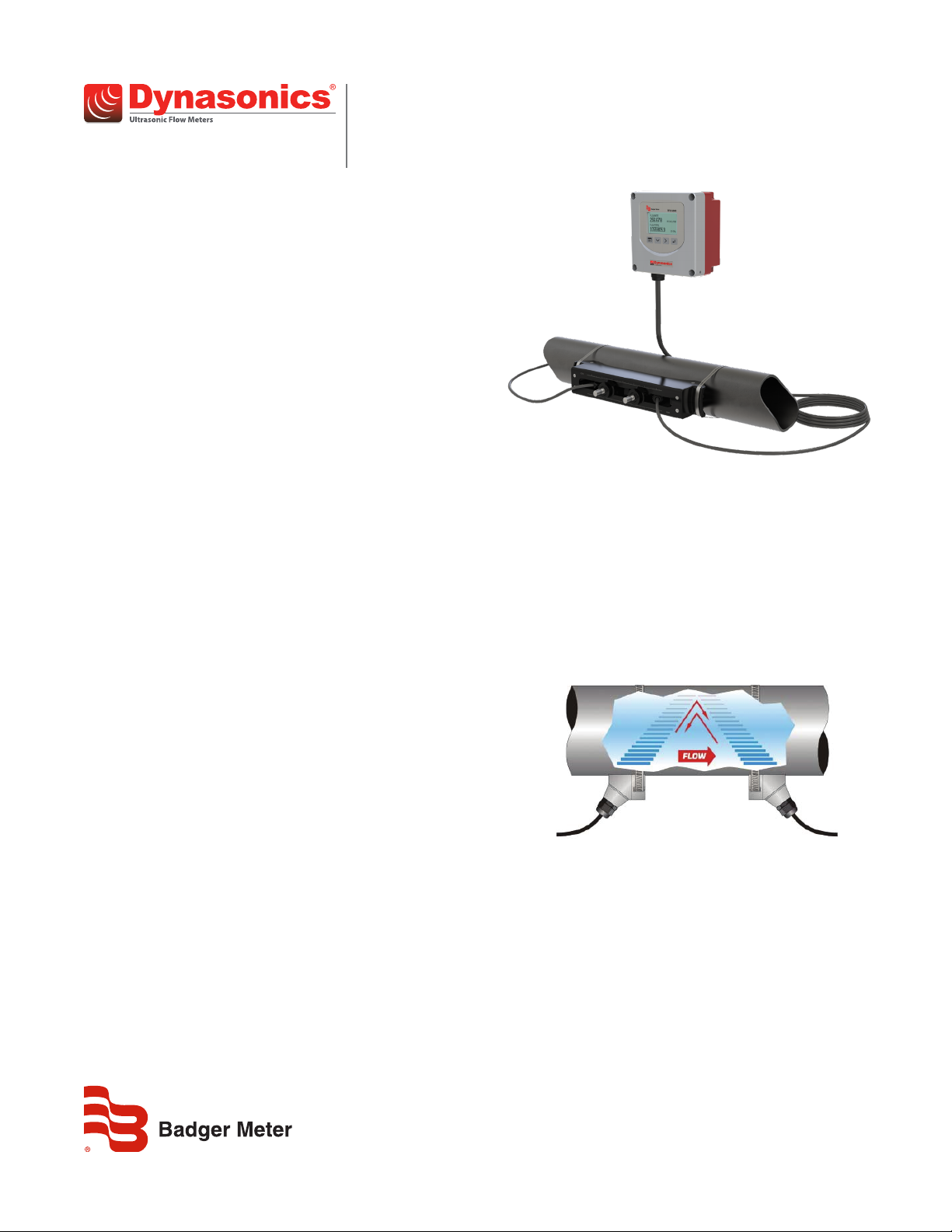
TFX-5000 Meter
DESCRIPTION
The TFX-5000 transit time ultrasonic flow meter measures
volumetric flow and heating/cooling energy rates in clean liquids as
well as those with small amounts of suspended solids or aeration,
such as surface water or raw sewage.
TFX-5000 flow and energy meters clamp onto the outside of pipes
and do not contact the internal liquid.
BENEFITS
By clamping onto the outside of pipes, the meters have inherent
advantages over other flow meter technologies, including:
• Reduced installation time and cost
• Non-invasive, non-contact measurement
• Continued operation during installation—no need to shut down
the process
• No pressure head loss
• No moving parts to maintain or replace
FEATURES
• Large, bi-directional flow measuring range
• Data log up to 8 records
• Modbus® RTU or BACnet® MS/TP over EIA-485; BACnet/IP,
EtherNet/IP, or Modbus TCP/IP; AquaCUE®/BEACON® connectivity
• Configure and troubleshoot over USB with SoloCUE
• Reynolds, ultrasonic speed and temperature compensation
• Large, easy-to-read graphical display
• Rugged, aluminum enclosure for a long service life in
harsh environments
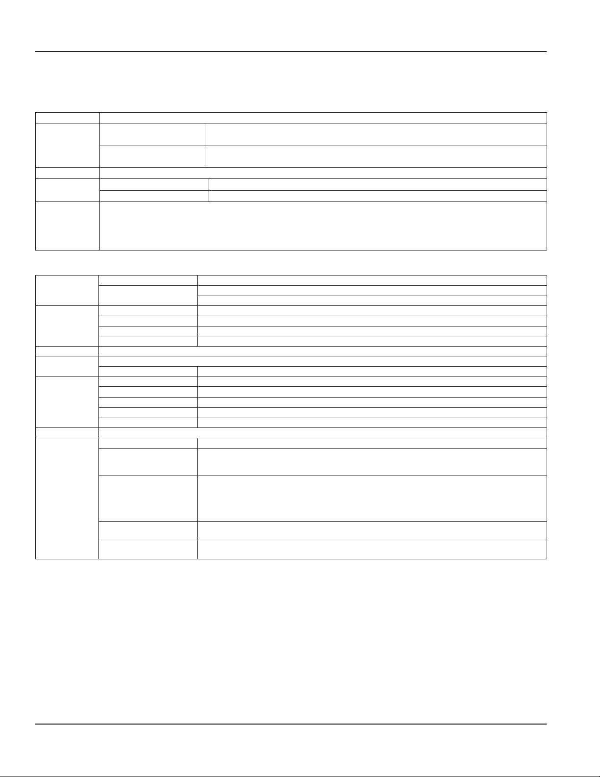
OPERATION
Transit time flow meters measure the time difference between
the travel time of an ultrasound wave going with the fluid flow
and against the fluid flow. The time difference is used to calculate
the velocity of the fluid traveling in a closed-pipe system. The
transducers used in transit time measurements operate alternately
as transmitters and receivers. Transit time measurements are
bi-directional and are most effective for fluids that have low
concentrations of suspended solids and are sonically conductive.
APPLICATIONS
The TFX-5000 meter is available in a variety of configurations that
permit the user to select a meter with features suitable to meet
particular application requirements.
The TFX-5000 meter is available in two versions:
• A flow meter for water delivery, sewage, cooling water,
water-glycol mixtures, alcohols and chemicals
• A heating/cooling energy flow meter used in conjunction with
dual clamp-on RTDs for temperature measurement—ideal for
hydronic process and HVAC applications
TTM-DS-02221-EN-01 (August 2019)
An ultrasonic meter equipped with heat flow capabilities measures
the rate and quantity of heat delivered or removed from devices
such as heat exchangers. By measuring the volumetric flow rate of
the heat exchanger liquid, the temperature at the inlet pipe and
the temperature at the outlet pipe, the energy usage can
be calculated.
Product Data Sheet
Page 2
Transit Time Ultrasonic Flow Meters, TFX-5000 Meter
SPECIFICATIONS
System
Liquid Types Most clean liquids or liquids containing small amounts of suspended solids or gas bubbles
Medium and Large Pipes (RZ,
Flow Accuracy
Repeatability 0.2% above 1.5 ft/s
Velocity
Certification and
Compliance
NZ, WZ, HZ, LZ, YZ, JZ, KZ)
Small Pipes (CA-CT, UZ)
Medium and Large Pipes Up to 40 ft/s, depending on pipe and fluid
Small Pipes Up to 20 ft/s, depending on pipe and fluid
General Safety (all models): cCSAus, CE, Pollution Degree 2, CE compliance to Low Voltage Directive, 2014/35/EU
Hazardous Location transmitter and transducers:
CSA-c-us Class I Division 2 Groups ABCD T4
Requires flexible conduit
Not available with UZ, HZ or JZ and KZ (Easy Rail) transducers, Auxiliary Dry Contact card or units with AquaCUE/BEACON endpoints
Transmitter
24V DC/AC 9…28V DC @ 8 W max. or 20…26 AC 47…63 Hz @ 0.5 A max., 2 Amp slow-blow fuse, not eld replaceable
Power Options
Display
Enclosure NEMA Type 4, IP67
Construction
Environmental
Ratings
Conguration Via optional keypad or SoloCUE conguration software; SoloCUE available on DVD
Units
(FieldSelectable)
Mains AC
Options Display with keypad or no display/keypad
Keypad 4-button navigation, keypad with tactile feedback; polyester lm
Display 128 × 64 pixel LED backlit graphical display; adjustable brightness and timeout; polycarbonate window
Flow rate/total 8-digit
Aluminum construction; painted; wall, panel or pipe mounting; stainless steel fasteners and mounting hardware; EPDM gasket
Conduit Holes (4) 1/2 in. NPT, M20 × 1.5 or 1/2 BSPP; cable glands available for NPT and M20
Pollution Degree 2
Altitude Restriction Up to 2000 m (6561 ft)
Ambient Temperature Range –4…140° F (–20…60° C)
Storage Temperature Range –40…176° F (–40…80° C)
Humidity 0…85%, non-condensing
Velocity feet/second, meters/second
Volumetric total
Flow rate
Energy total
(energy meters)
Heat/cooling rate
(energy meters)
± 0.5% ± 0 0.049 ft/s (0.015 m/s)
1 in. (25 mm) and larger = ±1% ± 0.03 ft/s (0.009 m/s)
3/4 in. (19 mm) and smaller = ±1% of full scale
85…264V AC 47…63 Hz @ 24VA max. 1 Amp slow-blow fuse, manually eld replaceable
Over-Voltage Rating Category II (CAT II)
US Gallons, Million Gallons, Imperial Gallons, Million Imperial Gallons, Acre-Feet, Liters, Hectoliters,
Cubic Meters, Cubic Feet, Oil Barrels (42 gallons), Fluid Barrels (31.5 gallons), Imperial Fluid Barrels
(36 imperial gallons), Pounds (Kilograms) and custom units
Acre Feet/Day, Liters/Second, Liters/Minute, Liters/Hour, Cubic Meters/Second, Cubic Meters/Minute,
Cubic Meters/Hour, Cubic Feet/Minute, Cubic Feet/Minute, Cubic Feet/Hour, Gallons/Second,
Gallons/Minute, Gallons/Hour, Million Gallons/Day, Imperial Gallons/Second, Imperial Gallons/Minute,
Imperial Gallons/Hour, Million Imperial Gallons/Day, Oil Barrels/Day, Fluid Barrels/Day,
Imperial Fluid Barrels/Day and custom units
British Thermal Unit (Btu), Thousand Btu, Millions Btu, Kilocalories, Mega calories, Kilowatt-hour,
Megawatt hour, Kilojoules, Mega joules, Ton-hour (Refrigeration)
Btu/hour, Thousand Btu/hour, Millions Btu/hour, Ton (Refrigeration), Watts, Kilowatts, Megawatts,
Kilojoules/hour, Mega joules/hour, Kilocalories/hour, Mega calories/hour
Page 2 August 2019
TTM-DS-02221-EN-01
Page 3
Flow Meter Energy Meter
0/4…20 mA output
One 16-bit, isolated, max 800 Ohms, internal or
external power
Two 16-bit, isolated, max 800 Ohms, internal or
external power
Digital input One 5…30V DC, isolated, externally or internally sourced, reset totalizer or alarm output
Inputs and
Outputs
Digital output
Two selectable pulse, alarm, ow direction, sink isolated
open collector, 5…30V DC, max. 50 mA externally or
internally sourced
Frequency output: 50% duty cycle, 63…10k Hz maximum frequency
Three selectable pulse, frequency, alarm, ow direction,
isolated open collector, 5…30V DC, externally or
internally sourced
Pulse (totalizer) output: 5 kHz max. output, open collector, pulse width 5…500 ms programmable
Optional: Two dry contact output for alarm or ow direction 30V DC max., 5A max.
(Ethernet not available with this option)
RTD (energy only) None
Two 2-wire, 3-wire or 4-wire Pt100/Pt1000 RTD inputs;
Range of –40…200° C; Clamp-on resistor kits available
Programming USB 2.0 mini B connector for connection to a device with SoloCUE conguration software
Ports
EIA-485
Modbus RTU command set or BACnet MS/TP; Baud rates 9600, 14400,19200, 38400, 57600, 76800, 115k;
terminating resistor selectable
Ethernet Optional 10/100 Base T RJ45, communication via Modbus TCP/IP, EtherNet/IP, or BACnet/IP with webserver
AquaCUE/BEACON Connectivity to AquaCUE/BEACON endpoint (LTE cellular)
Up to 8 parameters per record. Selectable 1 second to 1 day
Transfer logs via memory card
Data Logging
Number of points
Real Time Clock Backed up with a super capacitor, minimum of 32 days of data retention without power; Requires no servicing
MicroSD card slot 8 GB card, included with transmitter
Alarms Records 150 previous alarms, warnings or errors
Languages English
Security Four levels: Read-only, Operator, Service and Admin; 6-digit passcode number; selectable auto logout
Product Data Sheet
Transducers
Model Construction
CA-CT
fixed small pipe
UZ
adjustable
small pipe
NZ
standard pipe
RZ
standard pipe
JZ, KZ
standard pipe,
integrated rail
WZ
standard pipe,
submersible
HZ
high temperature
LZ
large pipe
YZ
large pipe,
submersible
Recommendations based on unlined, new pipes with water. Recommended pipe or tubing sizes vary with pipe conditions and uid.
PVC, CPVC, HDPE, PTFE, PDVF, stainless steel, ductile iron, aluminum, brass naval, carbon steel copper.
Large pipe transducers are recommended for 8…12 in. pipes if normal velocity is expected to be greater than 12 ft/s (3.6 m/s).
Consult factory for larger pipe sizes.
CPVC, Ultem®, Nylon cord grip
Polyethylene cable jacket;
–40…194° F (–40…90° C)
CPVC, Ultem, and anodized
aluminum track system; Nickel-plated
brass connector with Teflon insulation;
–40…194° F (–40…90° C)
PVC, Ultem®, Nylon cord grip
Polyethylene cable jacket;
–40…194° F (–40…90° C)
PBT glass filled, Ultem®,
Nylon cord grip; PVC cable jacket;
–40…250° F (–40…121° C)
PBT glass filled, Ultem,
Nylon cord grip; PVC cable jacket;
–40…250° F (–40…121° C)
CPVC, Ultem, Nylon cord grip
Polyethylene cable jacket;
–40…194° F (–40…90° C)
PTFE, Vespel, Nickel-plated
brass cord grip; PFA cable jacket;
–40…350° F (–40…176° C)
CPVC, Ultem, Nylon cord grip
Polyethylene cable jacket;
–40…194° F (–40…90° C)
CPVC, Ultem, Nylon cord grip
Polyethylene cable jacket;
–40…194° F (–40…90° C)
Cable Length
Max.
Pipe/Tubing Sizes
100 ft (30 m) 0.5…2 in. (12…50 mm) 190 (720)
100 ft (30 m) 0.5…2 in. (12…50 mm) 190 (720) NEMA 12
300 ft (90 m) 2.5…12 in. (DN65…DN300) 4000 (15,000) NEMA 6/IP67
300 ft (90 m) 2.5…12 in. (DN65…DN300) 4000 (15,000) NEMA 6/IP67
300 ft (90 m)
2.5…6 in. (DN65…DN150)
2.5…12 in. (DN65…DN300)
300 ft (90 m) 2.5…12 in. (DN65…DN300) 4000 (15,000)
300 ft (90 m) 2.5…12 in. (DN65…DN300) 4000 (15,000) NEMA 6/IP67
300 ft (90 m) 8…48 in. (DN200…DN1200)
300 ft (90 m) 8…48 in. (DN200…DN1200)
Flow Rate
Max. GPM (LPM)
4000 (15,000) NEMA 6/IP67
3, 4
33,000 (125,000) NEMA 6/IP67
3, 4
33,000 (125,000) NEMA 6/IP68
Pipe/
Tubing
Materials
See 2
Protection
NEMA 6/IP67
NEMA 6P/
IP68
TTM-DS-02221-EN-01
Page 3 August 2019
Page 4
Transit Time Ultrasonic Flow Meters, TFX-5000 Meter
RTD Kits
Part Number Description Installation RTD Type Construction Temperature Range
68996-001 RTD matched pair; 15 ft (4.5 m) cable
68996-002 RTD matched pair; 50 ft (15 m) cable
68996-003 RTD matched pair; 100 ft (30 m) cable
Pipe clamp,
surface mount, IP54
Pt 1000, Class A
Aluminum body,
silicone cable jacket
-58…356° F
(14.4…180° C)
Data Logging Storage
Part Number Description
69032-001 MicroSD card, industrial grade, 8 GB
SoloCUE Flow Device Manager Software
The flow meter may be programmed through the keypad or with SoloCUE software. If the meter is ordered without a display/keypad, the
flow meter must be programmed with SoloCUE software. The software is used to configure, calibrate and communicate with TFX-5000
meters. Additionally, it has numerous troubleshooting tools to make diagnosing and correcting installation problems easier.
SoloCUE Used to configure, calibrate and troubleshoot flow meters and control valves; Software is compatible with Windows 7, 8, 10
USB Cable RC820648 USB 2.0 mini B connector to A connector, shielded
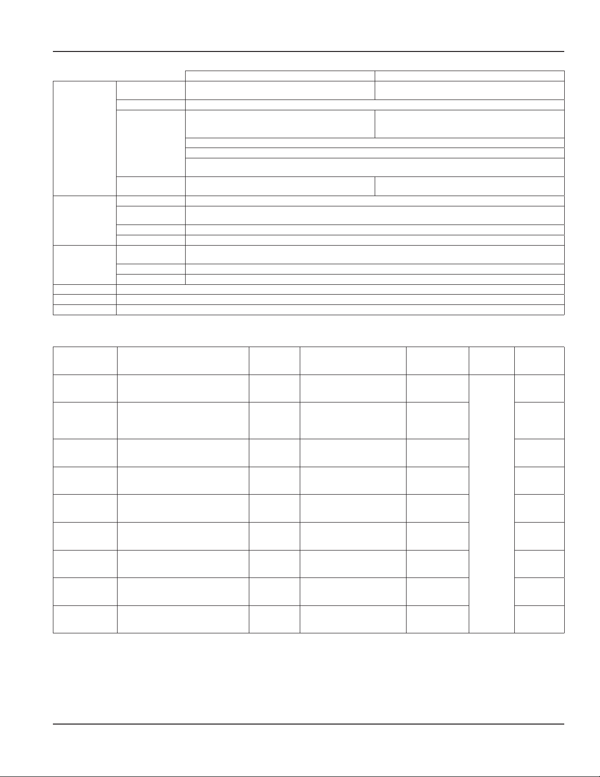
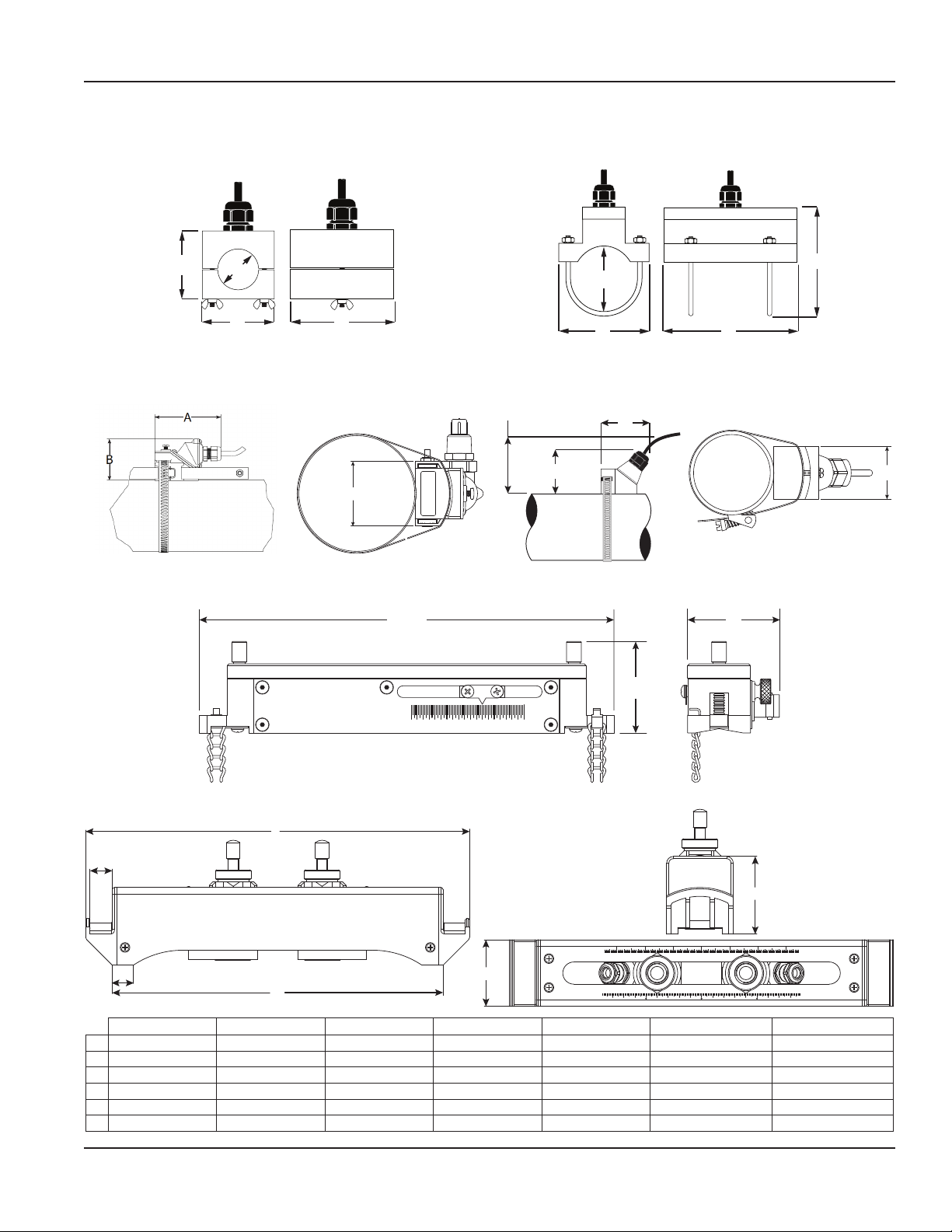
DIMENSIONS
Remote System Enclosure
6.50 in.
(165.10 mm)
3.63 in.
(92.20)
0.50 in.
(12.70 mm)
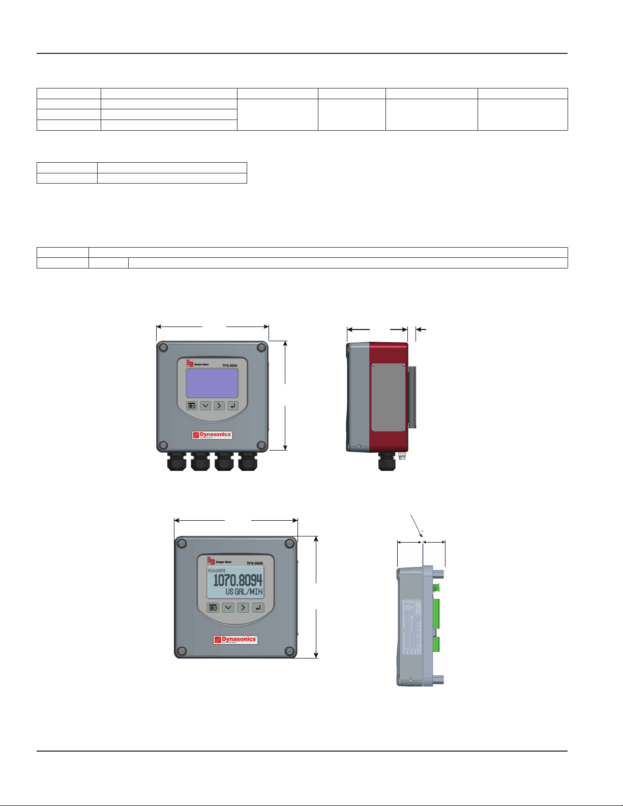
Panel Mount Enclosure
Torque the
cover screws
to 45 in-lb.
6.50 in.
(165.10 mm)
6.50 in.
(165.10 mm)
6.50 in.
(165.10 mm)
Customer-supplied panel
1.38 in.
(35.05 mm)
1.25 in.
(31.75 mm)
Consult factory for part number selection.
Page 4 August 2019
TTM-DS-02221-EN-01
Page 5
Product Data Sheet
B
A
D
C
B
D
A
C
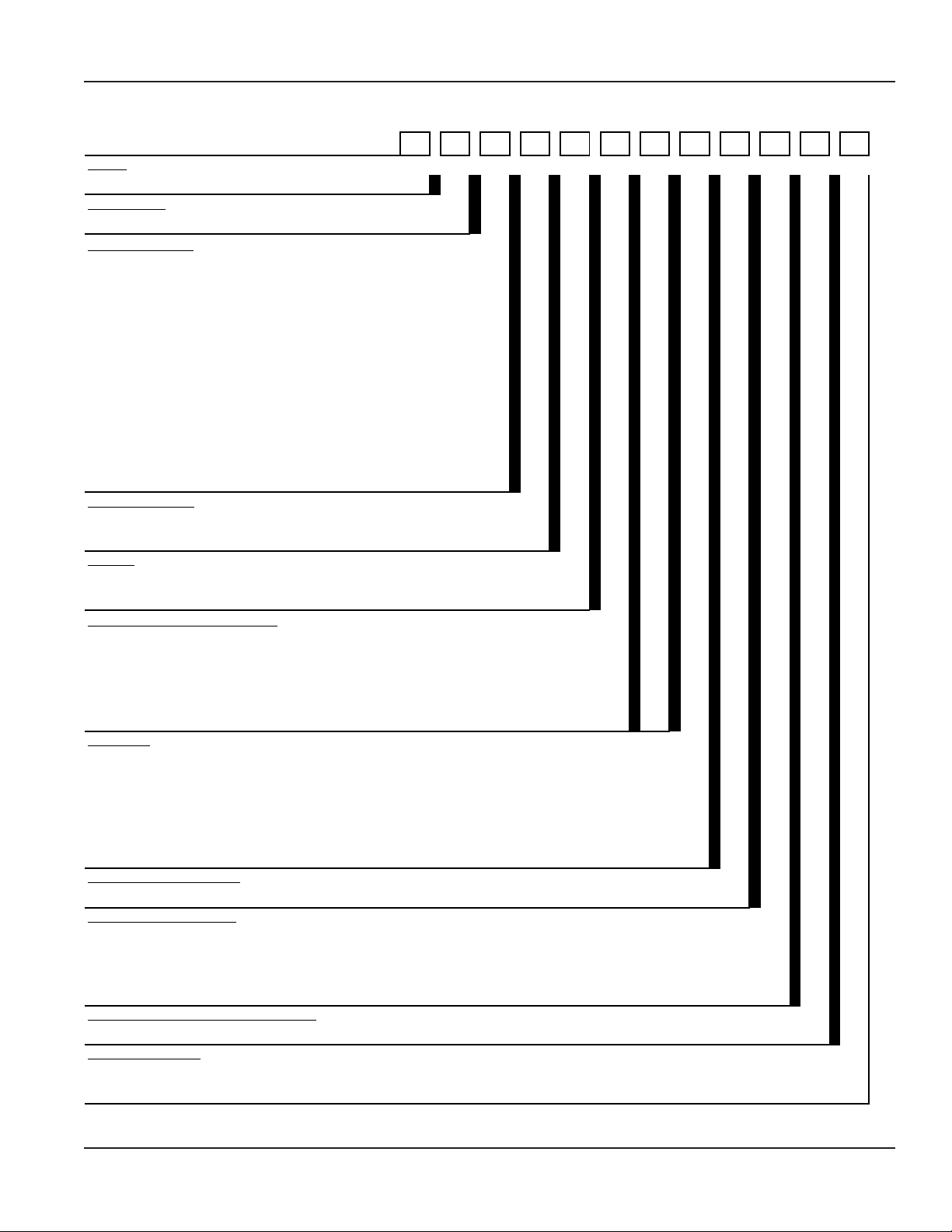
Transducers
Pipes and Tubing 1/2…2 in. (12…50 mm)
Fixed Small Pipe
RZ
Pipes Larger than 2 in. (50 mm)
D
TOP VIEW
OF PIPE
Fixed Small Pipe U-Bolt Connections CF, CL
(Min Clearance)
C
B
TOP VIEW
OF PIPE
ANSI/DN and Copper 2 in. (50 mm) Models
NZ, WZ, HZ, LZ, YZ
Pipes Larger than 2 in. (50 mm)
A
D
Adjustable Small Pipe
UZ
A B
C
0.3 1.51.0 2.0
Easy Rail (JZ, KZ)
A
D
E
inch
C
B
RZ NZ, WZ HZ LZ, YZ UZ JZ KZ
A 3.75 in. (95 mm) 2.95 in. (74.9 mm) 2.95 in. (74.9 mm) 3.40 in. (86.4 mm) 7 in. (178 mm) 13.62 in. (345.95 mm) 19.92 in. (505.97 mm)
B 2.35 in. (60 mm) 2.75 in. (69.8 mm) 2.75 in. (69.8 mm) 2.94 in. (74.7 mm) 1.6 in. (42 mm) 11.73 in. (297.94 mm) 18.03 in. (457.96 mm)
C — 3.00 in. (76.2 mm) 3.00 in. (76.2 mm) 3.20 in. (81.3 mm) 1.5 in. (39 mm) 0.75 in. (19.05 mm) 0.75 in. (19.05 mm)
D 2.19 in. (56 mm) 1.70 in. (43.2 mm) 1.71 in. (43.4 mm) 2.50 in. (63.5 mm) — 0.79 in. (20.06 mm) 0.79 in. (20.06 mm)
E — — — — — 2.76 in. (70.10 mm) 2.76 in. (70.10 mm)
F — — — — — 2.36 in. (59.94 mm) 2.36 in. (59.94 mm)
F
mm
TTM-DS-02221-EN-01
Page 5 August 2019
Page 6

Transit Time Ultrasonic Flow Meters, TFX-5000 Meter
Model
TFX-5000 Ultrasonic Clamp-On Meter DQ
Certification
General Area US/Canada, CE G
1
1/2 inch ANSI Pipe CA
3/4 inch ANSI Pipe CB
1 inch ANSI Pipe CC
1-1/4 inch ANSI Pipe CD
1-1/2 inch ANSI Pipe CE
2 inch ANSI Pipe CF
1/2 inch Copper Tube CG
3/4 inch Copper Tube CH
1 inch Copper Tube CT
1-1/4 inch Copper Tube CJ
1-1/2 inch Copper Tube CK
2 inch Copper Tube CL
Small pipe, universal (not available with conduit) UZ
Transmitter Type
110/220V AC Remote Mounted R
24V DC/AC Remote Mounted B
Display
Display and Keypad S
No Display/Keypad W
Remote Cable Length
15 feet (4.5 m) AC
30 feet (9 m) AF
50 feet (15 m) AK
75 feet (23 m) AR
100 feet (30 m) BW
Conduit Type and Length (Conduit length is less than or equal to cable length)
None WW
5 feet (1.5 m) AA
15 feet (4.5 m) AC
30 feet (9 m) AF
50 feet (15 m) AK
75 feet (23 m) AR
100 feet (30 m) BW
Hardware
1/2 in. NPT Threads, Poly cable glands S
1/2 in. NPT Threads, Nickel Plated Brass cable glands T
1/2 in. NPT Threads, no cable glands N
M20 Threads, Poly cable glands C
M20 Threads, Nickel Plated Brass cable glands D
M20 Threads, no cable glands A
Endpoint Wiring Method
None XX
Communication/Output
Standard Output (Modbus RTU or BACnet MS/TP field selectable) S
Standard Output plus Modbus TCP Ethernet T
Standard Output plus EtherNet/IP U
Standard Output plus BACnet/IP Ethernet V
Standard Output plus Aux Output 9
Units of Measure Totalizer/Flow Rate
Gallons/gallons per minute (field selectable, additional options available) G
Testing & Tagging
Factory Calibrated
F
Factory Calibrated/Stainless Steel Tag
S
1
Stainless steel tube 1/2…2 in. options are available.
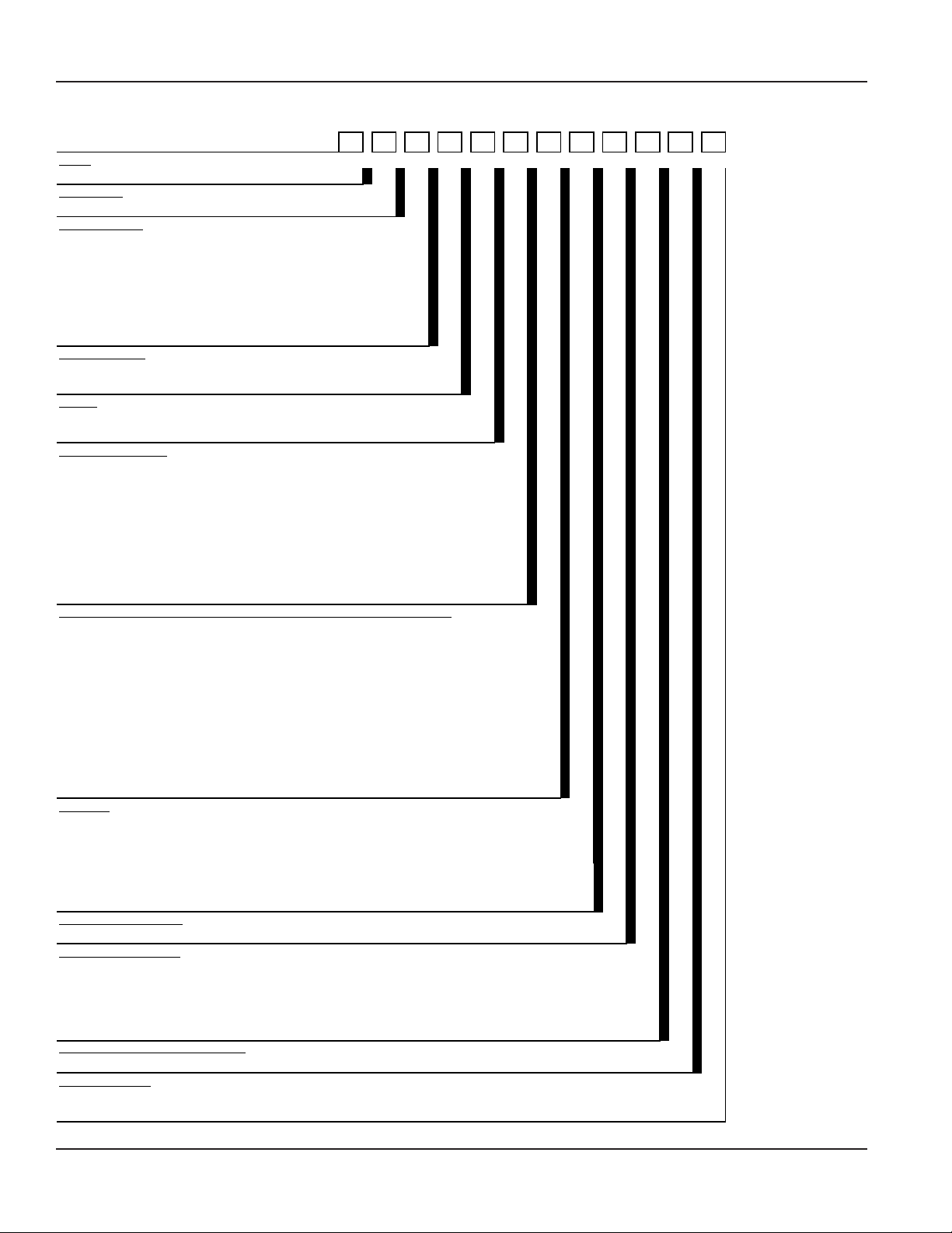
PART NUMBER CONSTRUCTION
Part Number Construction for TFX-5000 Flow Meters for Pipes 2 in. and Smaller
Transducer Type
DQ-G
- - - - - - -
XX
- - -
Page 6 August 2019
TTM-DS-02221-EN-01
Page 7
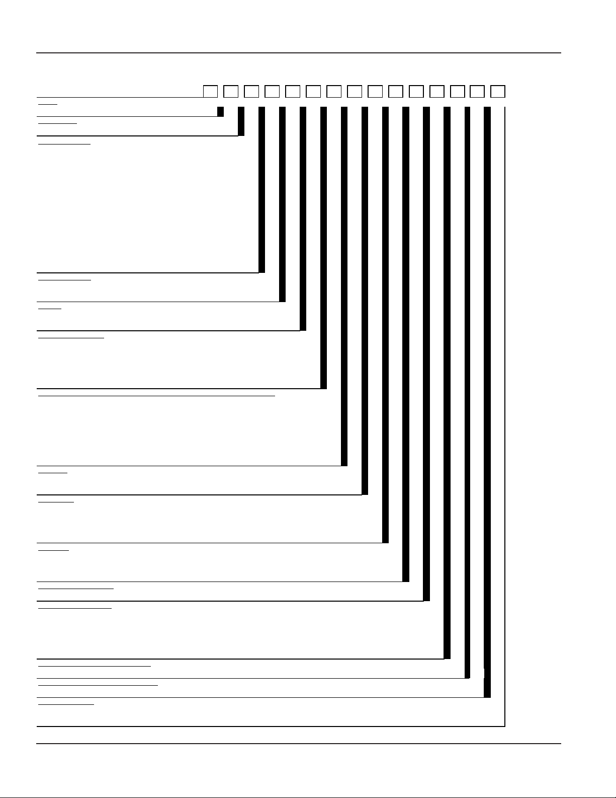
Part Number Construction for TFX-5000 Flow Meters for Pipes 2 in. and Smaller for Hazardous Locations
Model
TFX-5000 Ultrasonic Clamp-On Meter DQ
Certification
Hazardous Location, Class I, Division 2 B
1
1/2 inch ANSI Pipe CA
3/4 inch ANSI Pipe CB
1 inch ANSI Pipe CC
1-1/4 inch ANSI Pipe CD
1-1/2 inch ANSI Pipe CE
2 inch ANSI Pipe CF
1/2 inch Copper Tube CG
3/4 inch Copper Tube CH
1 inch Copper Tube CT
1-1/4 inch Copper Tube CJ
1-1/2 inch Copper Tube CK
2 inch Copper Tube CL
Transmitter Type
110/220V AC Remote Mounted R
24V DC/AC Remote Mounted B
Display
Display and Keypad S
No Display/Keypad W
2
15 feet (4.5 m) AC AC
30 feet (9 m) AF AF
50 feet (15 m) AK AK
75 feet (23 m) AR AR
100 feet (30 m) BW BW
Hardware
1/2 in. NPT Threads, Poly cable glands S
1/2 in. NPT Threads, Nickel Plated Brass cable glands T
1/2 in. NPT Threads, no cable glands N
M20 Threads, Poly cable glands C
M20 Threads, Nickel Plated Brass cable glands D
M20 Threads, no cable glands A
Endpoint Wiring Method
None XX
Communication/Output
Standard Output (Modbus RTU or BACnet MS/TP field selectable) S
Standard Output plus Modbus TCP Ethernet T
Standard Output plus EtherNet/IP U
Standard Output plus BACnet/IP Ethernet V
Units of Measure Totalizer/Flow Rate
Gallons/gallons per minute (field selectable, additional options available) G
Testing & Tagging
Factory Calibrated
F
Factory Calibrated/Stainless Steel Tag
S
1
2
For hazardous location units, Remote Cable and Conduit Length codes must match.
Transducer Type
DQ-B
- - - - - -
XX
- - -
Product Data Sheet
Remote Cable/Conduit Length
Stainless steel tube 1/2…2 in. options are available.
TTM-DS-02221-EN-01
Page 7 August 2019
Page 8
Transit Time Ultrasonic Flow Meters, TFX-5000 Meter
Model
Certification
Transducer Type
Medium pipe, submersible, 2.5 in. (65 mm) or larger
1
WZ
Medium pipe, high temperature (not available with conduit)
Large pipe, submersible, 8 in. (200 mm) or larger
1
YZ
Transmitter Type
Display
Remote Cable Length
Conduit Type and Length (Conduit length is less than or equal to cable length.)
Hardware
Endpoint Wiring Method
Communication/Output
Units of Measure Totalizer/Flow Rate
Gallons/gallons per minute (field selectable, additional options available) G
Testing & Tagging
1
Part Number Construction for TFX-5000 Flow Meters for Pipes Larger than 2 in.
DQ-G
TFX-5000 Ultrasonic Clamp-On Meter DQ
General Area US/Canada, CE G
Medium pipe, 2.5 in. (65 mm) or larger RZ
2.5…6 inches (65…150 mm) Easy Rail (not available with conduit) JZ
2.5…12 inches (65…300 mm) Easy Rail (not available with conduit) KZ
Large pipe, 8 in. (200 mm) or larger LZ
110/220V AC Remote Mounted R
24V DC/AC Remote Mounted B
Display and Keypad S
No Display/Keypad W
15 feet (4.5 m) AC
30 feet (9 m) AF
50 feet (15 m) AK
75 feet (23 m) AR
100 feet (30 m) BW
150 feet (46 m) BK
200 feet (61 m) DW
250 feet (76 m) DK
300 feet (90 m) EW
- - - - - - -XX- - -
HZ
None WW
5 feet (1.5 m) AA
15 feet (4.5 m) AC
30 feet (9 m) AF
50 feet (15 m) AK
75 feet (23 m) AR
100 feet (30 m) BW
150 feet (46 m) BK
200 feet (61 m) DW
250 feet (76 m) DK
300 feet (90 m) EW
1/2 in. NPT Threads, Poly cable glands S
1/2 in. NPT Threads, Nickel Plated Brass cable glands T
1/2 in. NPT Threads, no cable glands N
M20 Threads, Poly cable glands C
M20 Threads, Nickel Plated Brass cable glands D
M20 Threads, no cable glands A
None XX
Standard Output (Modbus RTU or BACnet MS/TP field selectable) S
Standard Output plus Modbus TCP Ethernet T
Standard Output plus EtherNet/IP U
Standard Output plus BACnet/IP Ethernet V
Standard Output plus Aux Output 9
Factory Calibrated F
Factory Calibrated/Stainless Steel Tag S
Submersible transducer cables use two conduit openings.
Page 8 August 2019
TTM-DS-02221-EN-01
Page 9

Part Number Construction for TFX-5000 Flow Meters for Pipes Larger than 2 in. for Hazardous Locations
DQ-B
- - - - - - -
XX
- -
Model
Certification
Hazardous Location, Class I, Division 2
B
Transducer Type
Medium pipe, submersible, 2.5 in. (65 mm) or larger
1
WZ
Large pipe, submersible, 8 in. (200 mm) or larger
1
YZ
Transmitter Type
Display
2
Hardware
Endpoint Wiring Method
Communication/Output
Units of Measure Totalizer/Flow Rate
Gallons/gallons per minute (field selectable, additional options available) G
Testing & Tagging
Factory Calibrated/Stainless Steel Tag
S
2
TFX-5000 Ultrasonic Clamp-On Meter DQ
Medium pipe, 2.5 in. (65 mm) or larger RZ
Large pipe, 8 in. (200 mm) or larger LZ
110/220V AC Remote Mounted R
24V DC/AC Remote Mounted B
Standard S
No Display/Keypad W
Remote Cable/Conduit Length
15 feet (4.5 m) AC AC
30 feet (9 m) AF AF
50 feet (15 m) AK AK
75 feet (23 m) AR AR
100 feet (30 m) BW BW
150 feet (46 m) BK BK
200 feet (61 m) DW DW
250 feet (76 m) DK DK
300 feet (90 m) EW EW
Product Data Sheet
1/2 in. NPT Threads, Poly cable glands S
1/2 in. NPT Threads, Nickel Plated Brass cable glands T
1/2 in. NPT Threads, no cable glands N
M20 Threads, Poly cable glands C
M20 Threads, Nickel Plated Brass cable glands D
M20 Threads, no cable glands A
None XX
Standard Output (Modbus RTU or BACnet MS/TP field selectable) S
Standard Output plus Modbus TCP Ethernet T
Standard Output plus EtherNet/IP U
Standard Output plus BACnet/IP Ethernet V
Factory Calibrated
1
Submersible transducer cables use two conduit openings.
For hazardous location units, Remote Cable and Conduit Length codes must match.
F
TTM-DS-02221-EN-01
Page 9 August 2019
Page 10
Transit Time Ultrasonic Flow Meters, TFX-5000 Meter
Model
TFX-5000 Ultrasonic Clamp-On Meter DR
Certification
General Area US/Canada, CE G
Transducer Type
1
1/2 inch ANSI Pipe CA
3/4 inch ANSI Pipe CB
1 inch ANSI Pipe CC
1-1/4 inch ANSI Pipe CD
1-1/2 inch ANSI Pipe CE
2 inch ANSI Pipe CF
1/2 inch Copper Tube CG
3/4 inch Copper Tube CH
1 inch Copper Tube CT
1-1/4 inch Copper Tube CJ
1-1/2 inch Copper Tube CK
2 inch Copper Tube CL
Small pipe, universal, DTTSU (not available with conduit) UZ
Transmitter Type
110/220V AC Remote Mounted R
24V DC/AC Remote Mounted B
Display
Display and Keybad S
No Display/Keypad W
Remote Cable Length
15 feet (4.5 m) AC
30 feet (9 m) AF
50 feet (15 m) AK
75 feet (23 m) AR
100 feet (30 m) BW
Conduit Type and Length (Conduit length is less than or equal to cable length)
None WW
5 feet (1.5 m) AA
15 feet (4.5 m) AC
30 feet (9 m) AF
50 feet (15 m) AK
75 feet (23 m) AR
100 feet (30 m) BW
RTD Type
Surface, Commercial C
None (user provided) X
RTD Length
15 feet AC
50 feet AK
100 feet BW
None (user provided) WW
Hardware
1/2 in. NPT Threads, Poly cable glands S
1/2 in. NPT Threads, Nickel Plated Brass cable glands T
1/2 in. NPT Threads, no cable glands N
Endpoint Wiring Method
None XX
Communication/Output
Standard Output (Modbus RTU or BACnet MS/TP field selectable) S
Standard Output plus Modbus TCP Ethernet T
Standard Output plus EtherNet/IP U
Standard Output plus BACnet/IP Ethernet V
Standard Output plus Auxilliary Dry Contact Output 9
Units of Measure Totalizer/Flow Rate
Gallons/gallons per minute (field selectable, additional options available) G
Units of Measure Energy Totalizer/Rate
Kilowatt-hour/Watt (field selectable, additional options available)
R
Testing & Tagging
Factory Calibrated
F
Factory Calibrated/Stainless Steel Tag
S
Part Number Construction for TFX-5000 Energy Meters for Pipes 2 in. and Smaller
DR-G
- - - - - - - - -XX- - - -
1
Stainless steel tube 1/2…2 in. options are available.
Page 10 August 2019
TTM-DS-02221-EN-01
Page 11
Part Number Construction for TFX-5000 Energy Meters for Pipes Larger than 2 in.
DR-G
- - - - - - - - -XX- - - -
Model
Certification
Transducer Type
Medium pipe, submersible, 2.5 in. (65 mm) or larger
1
WZ
Large pipe, submersible, 8 in. (200 mm) or larger
1
YZ
Transmitter Type
Display
Conduit Type and Length (Conduit length is less than or equal to cable length)
RTD Type
RTD Length
Hardware
Endpoint Wiring Method
Communication/Output
Units of Measure Totalizer/Flow Rate
Gallons/gallons per minute (field selectable, additional options available) G
Units of Measure Energy Totalizer/Rate
Testing & Taggin g
TFX-5000 Ultrasonic Clamp-On Meter DR
General Area US/Canada, CE G
Medium pipe, 2.5 in. (65 mm) or larger RZ
2.5…6 inches (65…150 mm) Easy Rail (not available with conduit) JZ
2.5…12 inches (65…300 mm) Easy Rail (not available with conduit) KZ
Medium pipe, high temperature (not available with conduit) HZ
Large pipe, 8 in. (200 mm) or larger LZ
110/220V AC Remote Mounted R
24V DC/AC Remote Mounted B
Standard S
No Display/Keypad W
Remote Cable Length
15 feet (4.5 m) AC
30 feet (9 m) AF
50 feet (15 m) AK
75 feet (23 m) AR
100 feet (30 m) BW
150 feet (46 m) BK
200 feet (61 m) DW
250 feet (76 m) DK
300 feet (90 m) EW
Product Data Sheet
None WW
5 feet (1.5 m) AA
15 feet (4.5 m) AC
30 feet (9 m) AF
50 feet (15 m) AK
75 feet (23 m) AR
100 feet (30 m) BW
150 feet (46 m) BK
200 feet (61 m) DW
250 feet (76 m) DK
300 feet (90 m) EW
Surface, Commercial C
None (user provided) X
15 feet (4.5 m) AC
50 feet (15 m) AK
100 feet (30 m) BW
None (user provided) WW
1/2 in. NPT Threads, Poly cable glands S
1/2 in. NPT Threads, Nickel Plated Brass cable glands T
1/2 in. NPT Threads, no cable glands N
M20 Threads, Poly cable glands C
M20 Threads, Nickel Plated Brass cable glands D
M20 Threads, no cable glands A
None XX
Standard Output (Modbus RTU or BACnet MS/TP field selectable) S
Standard Output plus Modbus TCP Ethernet T
Standard Output plus EtherNet/IP U
Standard Output plus BACnet/IP Ethernet V
Standard Output plus Aux Output 9
Kilowatt-hour/Kilowatt (field selectable, additional options available) R
Factory Calibrated F
Factory Calibrated/Stainless Steel Tag S
1
Submersible transducer cables use two conduit openings.
TTM-DS-02221-EN-01
Page 11 August 2019
Page 12

Transit Time Ultrasonic Flow Meters, TFX-5000 Meter
Control. Manage. Optimize.
Dynasonics, AquaCUE and SoloCUE are registered trademarks of Badger Meter, Inc. Other trademarks appearing in this document are the property of their respective entities. Due
to continuous research, product improvements and enhancements, Badger Meter reserves the right to change product or system specications without notice, except to the extent
an outstanding contractual obligation exists. © 2019 Badger Meter, Inc. All rights reserved.
www.badgermeter.com
The Americas | Badger Meter | 4545 West Brown Deer Rd | PO Box 245036 | Milwaukee, WI 53224-9536 | 800-876-3837 | 414-355-0400
México | Badger Meter de las Americas, S.A. de C.V. | Pedro Luis Ogazón N°32 | Esq. Angelina N°24 | Colonia Guadalupe Inn | CP 01050 | México, DF | México | +52-55-5662-0882
Europe, Eastern Europe Branch Oce (for Poland, Latvia, Lithuania, Estonia, Ukraine, Belarus) | Badger Meter Europe | ul. Korfantego 6 | 44-193 Knurów | Poland | +48-32-236-8787
Europe, Middle East and Africa | Badger Meter Europa GmbH | Nurtinger Str 76 | 72639 Neuen | Germany | +49-7025-9208-0
Europe, Middle East Branch Oce | Badger Meter Europe | PO Box 341442 | Dubai Silicon Oasis, Head Quarter Building, Wing C, Oce #C209 | Dubai / UAE | +971-4-371 2503
Slovakia | Badger Meter Slovakia s.r.o. | Racianska 109/B | 831 02 Bratislava, Slovakia | +421-2-44 63 83 01
Asia Pacic | Badger Meter | 80 Marine Parade Rd | 19-07 Parkway Parade | Singapore 449269 | +65-63464836
Switzerland | Badger Meter Swiss AG | Mittelholzerstrasse 8 | 3006 Bern | Switzerland | +41-31-932 01 11
 Loading...