

Page 1

ProDesk-4
OWNER’S MANUAL
APB-DynaSonics, Inc.
20 West End Road
Totowa, New Jersey, 07512, U.S.A.
Tel: 973-785-1101
Fax: 973-785-1105
Web: www.apb-dynasonics.com
Page 2

APB-DynaSonics
2
Page 3

ProDesk-4 OWNER’S MANUAL
IMPORTANT SAFTEY INSTRUCTIONS
1) Read These Instructions
2) Keep These Instructions
3) Heed All Warnings
4) Follow All Instructions
5) Do Not Use this Apparatus near water
6) WARNING: To reduce the risk of fire or electric shock, do not expose this apparatus to rain or
moisture. Do not expose the apparatus to dripping or splashing. Do not place objects
containing liquids, such as vases, on the apparatus.
7) For safety the AC supply must include third wire protective ground connection.
8) Do not block any ventilation openings at the front and rear. Install in accordance with the
manufacturer’s instructions.
9) Do not install near any heat sources such as radiators, heat registers, stoves or other apparatus
(including amplifiers) that produce heat.
10) Do not defeat the safety purpose of the polarized or grounding-type plug. A polarized plug has
two blades with one wider than the other. a grounding type plug has two blades and a third
grounding prong. The wide blade or the third prong is provided for your safety. If the provided
plug does not fit your outlet consult an electrician for replacement of the obsolete outlet.
11) Protect the power cord from being walked on or pinched particularly at plugs convenience
receptacles and the point where they exit the apparatus.
12) Unplug this apparatus during lightning storms or when unused for long periods of time.
13) Refer all servicing to qualified service personnel. Servicing is required when the apparatus has
been damaged in any way, such as power supply cord or plug is damaged, liquid has been
spilled or objects have fallen into the apparatus, the apparatus has been exposed to rain or
moisture, does not operate normally or has been dropped.
3
Page 4

TABLE OF CONTENTS
PSU INSTALLATION................................................................................................................................................................................................ 6
OPERATION WITH DUAL POWER SUPPLIES ..............................................................................................................................................7
POWER SUPPLY PS450 - SPECIFICATION.................................................................................................................................................... 8
YOUR PRODESK-4 CONSOLE............................................................................................................................................................................. 9
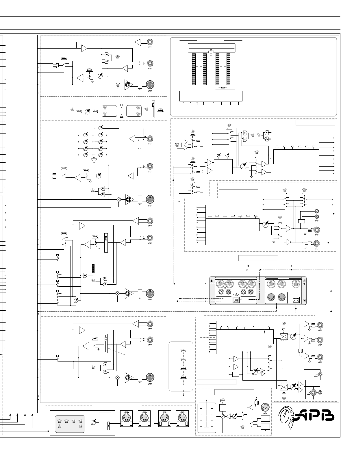
BLOCK DIAGRAM ( L ) ...................................................................................................................................................................................10
BLOCK DIAGRAM ( R )...................................................................................................................................................................................11
MONO INPUT ....................................................................................................................................................................................................12
MONO INPUT - EQUALIZATION...............................................................................................................................................................13
MONO INPUT - AUXILIARY SENDS.........................................................................................................................................................14
MONO INPUT - MUTE, SOLO
AND LEVEL CONTROL.......................................................................................................................15
MONO INPUT - BUS ASSIGNMENT AND PANNING .......................................................................................................................16
MONO INPUT - REAR PANEL CONNECTORS.....................................................................................................................................17
STEREO LINE INPUT........................................................................................................................................................................................18
STEREO LINE INPUT - STEREO EQUALIZATION................................................................................................................................19
STEREO LINE INPUT - AUX SENDS..........................................................................................................................................................20
STEREO LINE INPUT - MUTE, SOLO
AND LEVEL CONTROL ..........................................................................................................21
STEREO LINE INPUT - BUS ASSIGNMENT AND BALANCE...........................................................................................................22
STEREO LINE INPUT - REAR PANEL CONNECTORS ........................................................................................................................23
MASTER SECTION..................................................................................................................................................................................................24
AUXILIARY BUSES (1
GROUP OUTPUT (1
MATRIX OUTPUT (1
THRU 6) .......................................................................................................................................................................24
THRU 4) .........................................................................................................................................................................25
THRU 4) ........................................................................................................................................................................26
MAIN OUTPUT (L-R-C-M).............................................................................................................................................................................27
REAR PANEL CONNECTIONS (
FOR ALL 18 MAJOR BUSES) ..................................................................................................................28
STEREO PROGRAM IN ...................................................................................................................................................................................29
STEREO RECORD OUT (A
REAR PANEL CONNECTIONS
USB A
UDIO IN & OUT .........................................................................................................................................................................................31
LTERNATE OUT).................................................................................................................................................30
FOR STEREO PROGRAM IN AND STEREO RECORD OUT.....................................................................31
MONITOR / HEADPHONE CONTROL.....................................................................................................................................................32
SOLO SYSTEM- MONITOR
AND CONTROL...........................................................................................................................................33
TALKBACK SYSTEM ........................................................................................................................................................................................34
SOLO-LINKING
UTE-ALL CONFIGURATION ...............................................................................................................................................................................36
M
C
ONSOLE DIMENSIONS.........................................................................................................................................................................................37
AND MUTE-ALL....................................................................................................................................................................35
TECHNICAL SPECIFICATIONS....................................................................................................................................................................38
Page 5
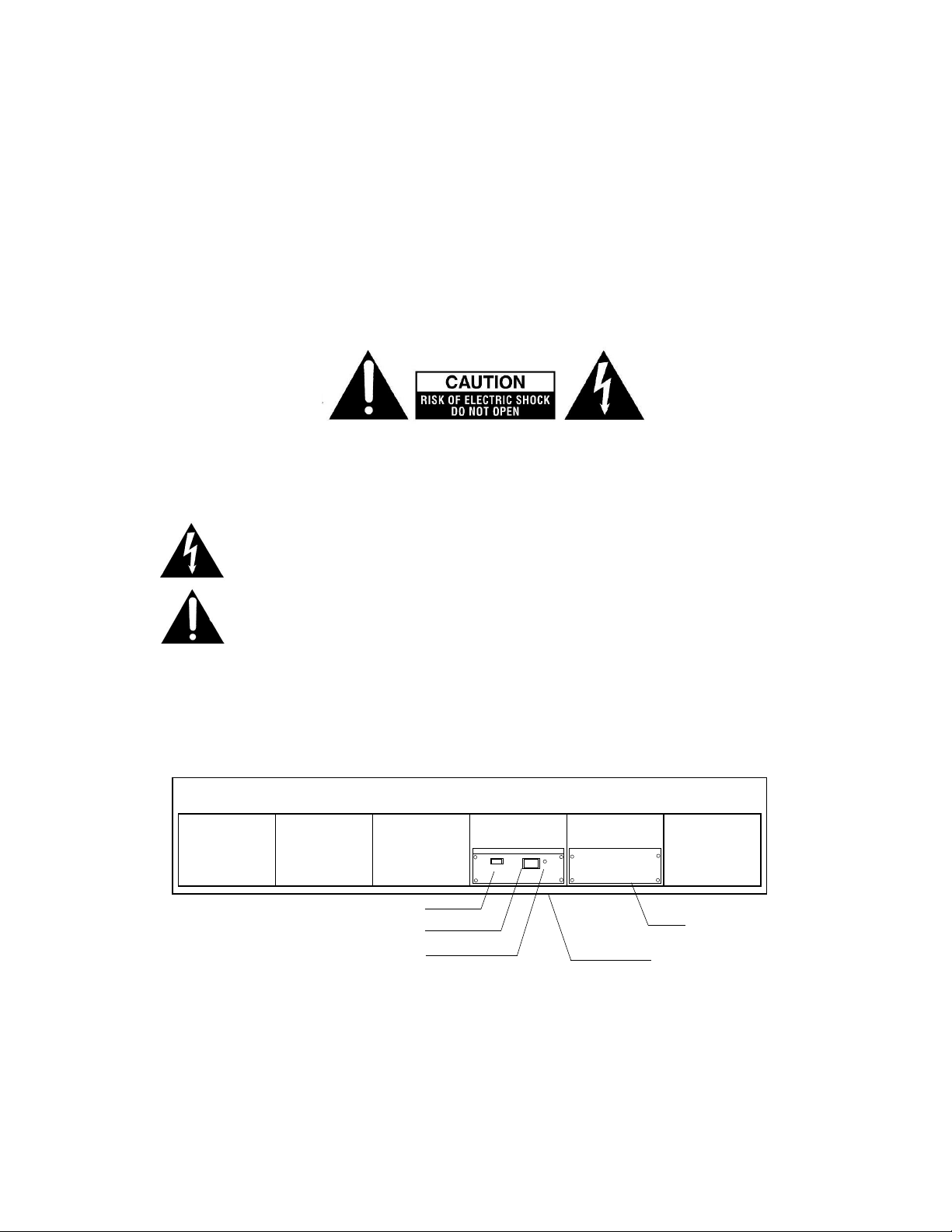
POWER SUPPLY Model PS450
THE SYMBOLS BELOW APPEAR IN THE TEXT THAT FOLLOWS AND HAVE THE FOLLOWING
ProDesk-4 OWNER’S MANUAL
MEANINGS:
TO AVOID ELECTRIC SHOCK FOLLOW THE INSTRUCTION NEXT TO THIS SYMBOL.
TO AVOID AN UNSAFE CONDITION FOLLOW THE INSTRUCTION NEXT TO THIS SYMBOL
REAR VIEW OF CONSOLE
POWER ON-OFF SWITCH
AC INLET CONNECTOR
POWER GOOD INDICATOR
PSU- B
PSU- A
5
Page 6
APB-DynaSonics
PSU INSTALLATION
This unit is for installation in APB DynaSonics sound mixing consoles and is intended for this purpose only. Complete
consoles are shipped with power supply(s) installed.
When adding a second power supply to an existing console or when replacing an existing power supply follow these
instructions:
1) Switch off AC power. Remove the AC power cord(s). Release the four screws holding the blanking cover plate, or
the existing power supply unit. Remove the cover plate or existing power supply unit. See the diagram for fastener
locations.
2) Insert the additional/replacement power supply unit into the opening and push it firmly to seat the connections.
Replace the four fasteners.
3)
Use the power cord supplied to connect a source of AC power between 100V and 240V 50/60Hz.
4) The maximum power requirement for the largest console is approximately 400VA.
5)
It is a safety requirement that the AC supply connection includes third wire protective ground connection.
6) Safe operation of the system requires flow of cooling air from the surroundings. Air intake is at the lower
front of the console. Air exhaust is at the upper rear of the console. These openings must not be covered while the
system is on. Low-noise, internal fans provide air movement.
OPERATION
Turn on each power supply using the rocker switch on the PS panel.
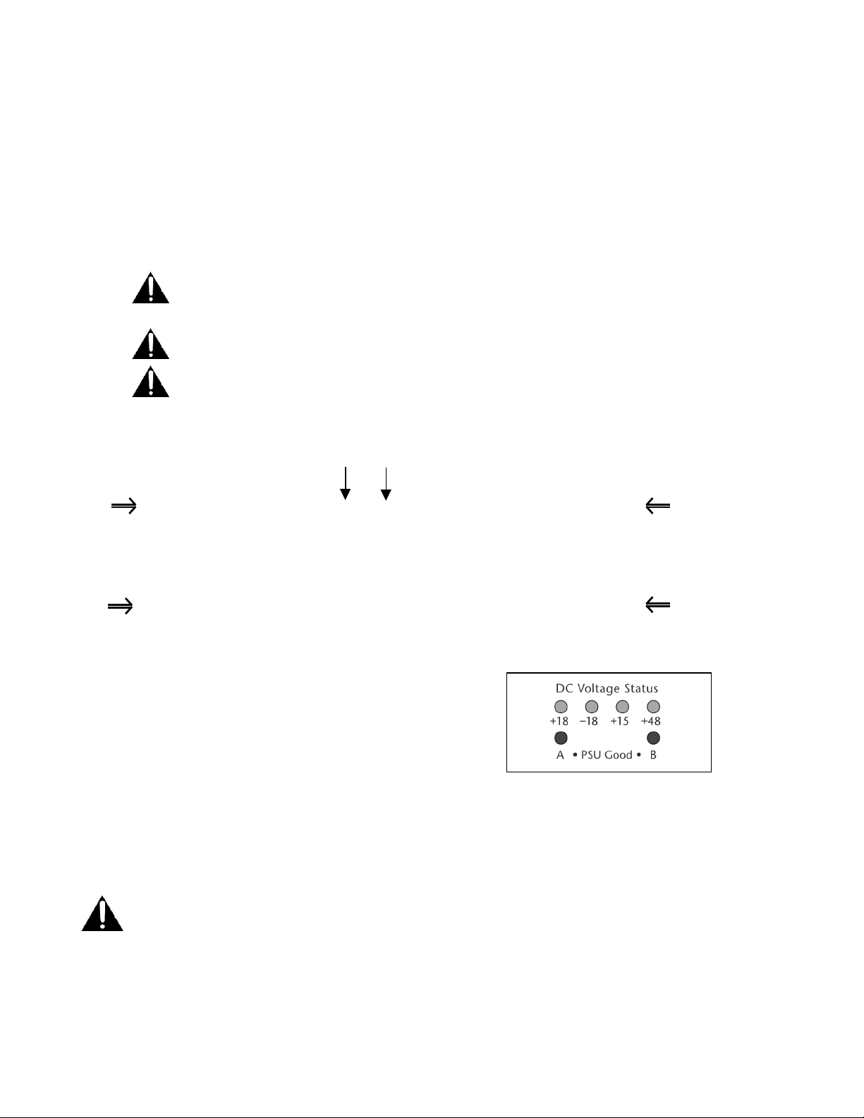
Normal operation is signaled by illumination of the four green DC voltage
indicators at the top center of the console and by the illumination of the
adjacent blue “PSU GOOD” indicator(s) and also the green “PSU GOOD”
indicator on each PS unit panel(s). The PSU Good condition is reached approx.
4 seconds after initial turn-on. This delay gives the Console’s internal circuits
time to stabilize and the PSU Good signal is then used to un-mute the main
outputs of the Console.
AC POWER ON OFF
NOTE: PS450 units will only operate when electrically connected to the console circuits. When removed from the
console chassis and when power is switched on, sensing circuits in the PS unit command a shutdown of the system.
In this condition the PS GOOD indicator on the PS panel will not illuminate and there will be no DC outputs. If this
occurs switch off, replace the unit in the console and wait 30 seconds before switching on.
Normal operation of the PS 450 requires unrestricted airflow through the unit for cooling. Fans operate at
all times and circulate air within the chassis. Ambient air reaches the PS via openings at the front of the
console. Ensure that the intake and exhaust openings are not obstructed.
6
Page 7
OPERATION WITH DUAL POWER SUPPLIES
A single PS450 power unit is conservatively rated to operate the 48 channel ProDesk console continuously. For
the assurance of fully redundant automatic back-up operation, the console chassis (24 chan and above)
accepts a second PS450 unit. When a second PS is present and powered, both power supplies operate and the
load is shared. Two independently protected sources of AC power are recommended for maximum protection
against loss of power.
1) Connect each power supply unit to AC power using the cable included.
2) The power supplies must both be switched on using the panel rocker switch on both units.
a. Normal operation is accompanied by the green illumination of the indicators on both units. In addition two
blue PS status indicators are located within view on the console light-bar.
b. If for any reason a supply goes into shutdown then console operation continues using the other unit, the
changeover is automatic and seamless. This event would be signaled by loss of a blue PSU status indicator.
REPLACEMENT OF POWER SUPPLY UNITS
1) Disconnect the AC power cord.
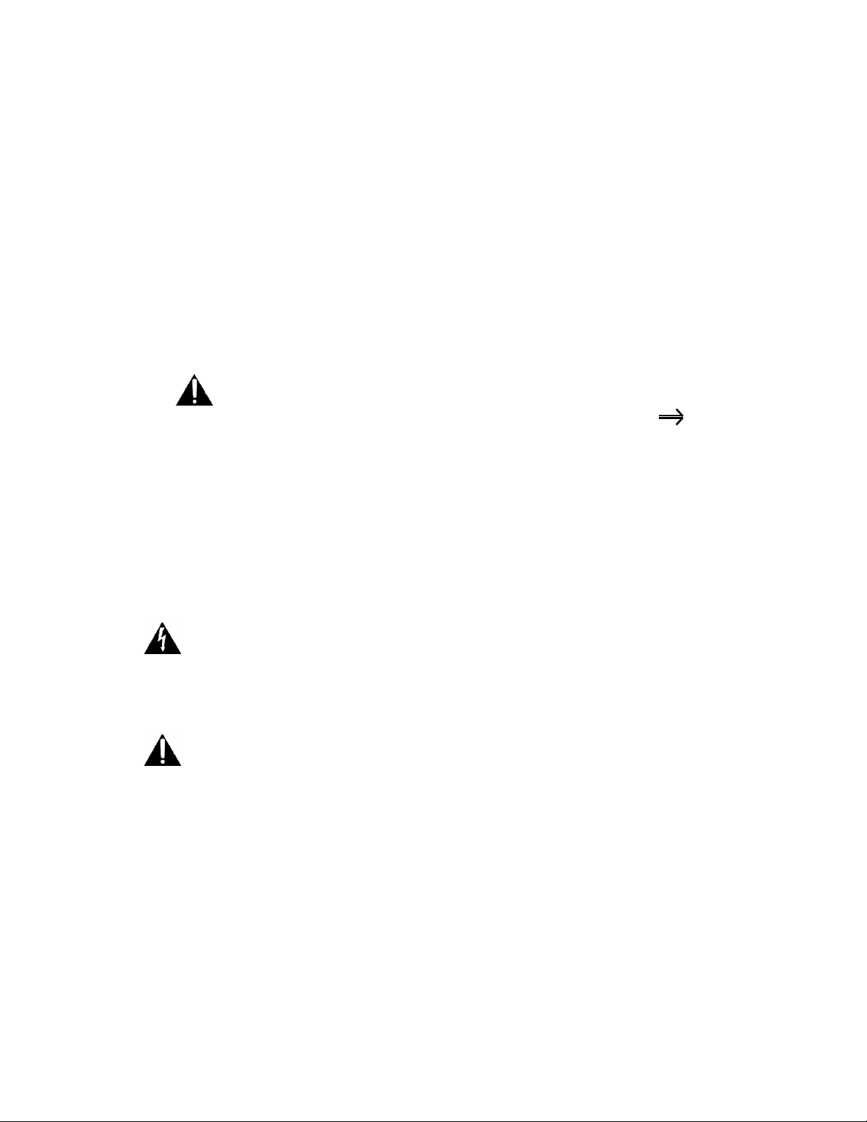
2) Remove four screws that secure the PS unit in the console chassis marked with the symbol
in the diagram. Pull on the power supply handle and the complete unit will slide out of the console
chassis.
3) Slide the replacement unit into the console. Replace the four fixing screws.
4) Reconnect the AC power cord.
5) Switch on the power supply using the rocker switch on the panel.
6) Green illumination of the power supply panel indicator(s) and illumination of blue “PSU GOOD” indicators
on the upper console control surface signal normal operation.
7) Note that the power supply units will not operate outside of the console. Automatic circuits prevent
operation if the unit is switched on while out of the console.
SERVICING
CAUTION RISK OF ELECTRIC SHOCK. DO NOT OPEN THE POWER SUPPLY.
There are no user serviceable parts inside the PS unit enclosure.
Units contain hazardous AC and DC voltages.
Return defective units to APB-DynaSonics or authorized agent for servicing.
The unit will not operate outside a console. Automatic circuits prevent operation when disconnected from the
console. If this occurs: switch off, replace the unit in the console and wait 30 seconds before switching back on.
Page 8

APB-DynaSonics
POWER SUPPLY PS450 - SPECIFICATION
High efficiency switch-mode power supply
Zinc-plated steel enclosure with ventilation by internal fans
PS units plug into the APB ProDesk sound console chassis.
IEC 60320 C13 AC inlet connection
Universal AC input voltage and frequency 100-240V 50/60Hz
Power Factor corrected AC input
Multiple regulated DC outputs:
+/- 18V DC @ 10A audio system
+15V DC @ 4.5A fans, lights, control system
+48V DC @ 0.5A input phantom power
Multiple protection systems:
AC input primary fuse, PCB mounted wire ended 20x5mm T8A
AC input in-rush limiting by relay and thermistor
AC input overvoltage MOV clamp
AC input dual series RFI chokes
DC output short circuit protection
DC output overvoltage protection
Automatic safety interlock prevents operation outside the console
Automatic shut-down in the event of elevated & unsafe internal temperature
Approvals:
USA Recognized power supply with ETL marking and listing
th
USA and Canada UL60065 7
th
Europe EN60065 7
Edition Electrical Safety
Edition Electrical Safety
Europe EN55103-1 Emissions (Pending)
USA FCC Part 15 Emissions (Pending)
Principal Of Operation
Power is drawn from the AC line and rectified. A switching device maintains the voltage on the internal DC
reservoir capacitor within a controlled range. The main transformer operates at approximately 100kHz and
steps down the primary power from about 400VDC to the low voltages required for the four regulated
outputs. The high frequency low voltage AC is rectified to generate the DC output voltages required. The +/18V DC supplies for the audio system are coupled so that the voltage of the negative supply is a precise
mirror of the positive voltage. The 48V DC supply is further processed using a three-terminal regulator to
improve noise and regulation qualities. All DC outputs are short-circuit protected, the +/-18V supplies are
controlled as a pair.
8
Page 9

ProDesk-4 OWNER’S MANUAL
YOUR PRODESK-4 CONSOLE
Congratulations on your purchase of one of the finest live performance professional audio consoles manufactured in the
United States.
Please take a moment to review this manual. It will insure a better understanding of the operation of this console and
may open up new possibilities into how you use this product.
In addition to the hard copy of this manual, it will appear within our web site www.apb-dynasonics.com with the latest
updates as well as new supplemental information. We suggest that you occasionally check our web site for additional
information about your console as well as for new product releases and news from APB-DynaSonics.
Should you have any questions or comments about this APB-DynaSonics product, please do not hesitate to contact us at:
Tel: 973-785-1101
Fax: 973-785-1105
e-mail: [email protected]
Manual Scope
This manual is not intended to teach you how to mix or how to set up a complete sound system. Should you
be looking for such information, May we suggest that you do a Web Search for “Pro Audio Books” on the
Internet, or attend one of the many fine Recording Schools that may be available to you. Many of these schools
offer courses in Live Performance associated subjects as well as basic mixing techniques.
One of the BEST (and our favorite) sources of teaching the technical aspect of system design and operation is
through the Syn-Aud-Con organization:
Synergetic Audio Concepts, Inc.,
8780 Rufing Road
Greenville, IN, 47124 – USA
800-796-2831
Fax : 812-923-3610
For calls outside of the US: 812.923.0174
Email: [email protected]
www.synaudcon.com
9
Page 10
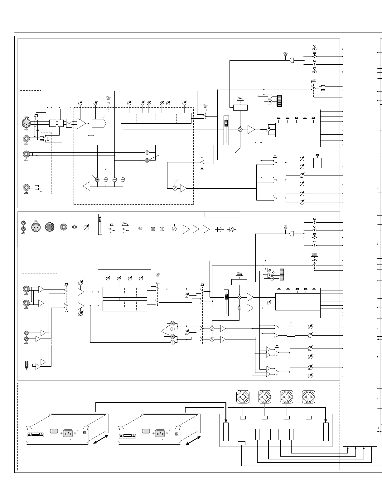
ProDesk-4 Block Diagram ProDesk-4 Block Diagram
ProDesk-4 Mono Inputs
Channels 1-48
Rear
Connector
Bal
XLR In
Panel
+48V
Pad
26dB
Pad
Line In
26dB
Pad
Tip
Ring
Insert
+4dBu
Direct
Out
+4dBu
Tip
Ring
RCA
Female
XLR
Male
XLR
- 6
Jacks
ProDesk-4 Stereo Inputs
4 Stereo Inputs (A-B-C-D)
Located In Master Section
Rear Connector Panel
Left
(Mono)
Right
- 6
Stereo
Line In
+4dBu
Stereo
Line In
-10dBV
L
R
For Stereo Inputs A-B-C
Rear-Panel RCA jacks
Alt Input from USB Audio In
+6
Alt Input is
+6
For Stereo Input D
+6
+6
Scene Mute Select
Remote
Mute
1
2
3
4
PFL
Solo Left
Grp
3-4
PFL
Grp
3-4
1-2
Stereo
1
2
3
4
5
6
1
2
3
4
Solo Right
Solo DC
Mono Bus
Center Bus
Left Bus
Right Bus
Group-1 Bus
Group-2 Bus
Group-3 Bus
Group-4 Bus
Aux Bus 1
Aux Bus 2
Aux Bus 3
Aux Bus 4
Aux Bus 5
Aux Bus 6
Solo Left
Solo Right
Solo DC
Mono Bus
Center Bus
Left Bus
Right Bus
Grp1 Bus
Grp2 Bus
Grp3 Bus
Grp4 Bus
Aux Bus 1
Aux Bus 2
Aux Bus 3
Aux Bus 4
Aux Bus 5
Aux Bus 6
Between Modules
Interconnection
Interconnection
Between Modules
Hi-Pass
-12dB/Oct
20Hz - 400Hz
HPF
To Peak
Circuit
Pre
Amp
100mm
Fader
HPF
On
From
Fader Amp
Post
Post
Insert
Fader
Direct Out
– User Options –
Small
Switch
Level
Hi Freq
10kHz
Hi Freq
10kHz
Pre
Fader
Illuminated
Switch
Level
Hi Mid
3kHz
Four Band EQ
Hi Mid
3kHz
Four Band EQ
Level
Hi Freq
10kHz
Shelf
Lo Mid
300Hz
Lo Mid
300Hz
Insert
Level
Level
Freq
Hi Mid
400 - 8kHz
Post
HPF
Post
Pre-EQ
– User Options –
Preamp / EQ
Sub-Board
Indicator
LED
Level
Lo Freq
60Hz
Lo Freq
60Hz
Four Band EQ
Internal User
Options
EQ On
Default
Setting
Lo Mid
80 - 2kHz
Default
Setting
LevelFreq
FET
Mute
FET
Switch
Aux
Pre-Source
Select
Level
Lo Freq
60Hz
Shelf
From
Mute Logic
Aux “Pre”
Buffer
∑
GP • Summing • X-Gain
Amplifiers
Chan
Pre
Fader
Blend
Aux
Pre
Aux
Blend
EQ On
Pre
Fader
Aux Pre
Pre-Fdr
Pre-EQ
Block Diagram Legends
10dB
Rectifier • Peak Det
Split
Track
100mm
Aux
Mute
FETs
Stereo
Fader
Switches
100mm
Channel
Metering
L
R
Pre-Aux
Buffers
From
Scene
Mute
Fader
Mute
Mute Logic
FET
Mute
To
Aux
Mutes
Mute
Mute Logic
FET
Mute
Mic Pre
10dB
Fader Amp
To
Direct Out
Options
10dB
10dB
Post-Fader
Buffer
From
Pk
8
Chan
0
LED
6
Meter
12
Sig
Grp
L-RCenterMono
Pan
Pot
1-2
Pre
3-4
Pre
5-6
Pre
1-2
Bus Assignment
and
Pan Circuitry
Aux Sends
1
2
3
4
5
6
Scene Mute Select
Remote
Mute
Pk
8
L
Chan
Sig
LED
Pk
Meter
8
R
Sig
Grp
L-RCenterMono
1-2
Balance
Pot
L
R
Assignment and Buffer
1-2
1-2
Pre
Stereo
3-4
3-4 Always
Pre
Summed Mono
5-6
5-6 Always
Pre
Summed Mono
Circuitry
Aux Sends
Gain
15 - 65 dB
Line
Polar ity
In
Default
Setting
Dir Out
Buffer
1/4”
1/8”
TRS
Line In
Source
(USB)
Rotary
TRS
Control
Gain Left
-20 to +20 dB
TRS
RCA
Gain Right
-20 to +20 dB
Power Supply
Model: PS-450
Plug-In Power Supply
ProDesk Rear Panel
PSU A
ETL Classified
PSU
Good
CAUTION
RISK OF ELECTRIC SHOCK
DO NOT OPEN
AVIS :
RISQUE DE CHOC ÉLECTRIQUE—NE PAS OUVRIR
The supplies are easily removed for service or replacement (4 screws) and can be hot-swapped.
APB-DynaSonics
ProDesk-4 Block Diagram Rev 0.92 16-July-09
Power
APB-DynaSonics
100-240V
Console Power Supply
50/60 Hz
Model PS-450
AC Inlet
15A IEC
an optional power supply can be fitted in all chassis sizes except for the 16-channel.
With 2 PSUs fitted, the total Console load is shared equally between the 2 supplies.
US C
3097042
Conforms to
ANSI/UL Std. 60065
Cert. To CAN/CSA
Std. C22.2 No. 60065
AC IN
500W
RISK OF ELECTRIC SHOCK
AVIS :
RISQUE DE CHOC ÉLECTRIQUE—NE PAS OUVRIR
CAUTION
DO NOT OPEN
The ProDesk-4 normally ships with 1 supply,
Power
APB-DynaSonics
Console Power Supply
Model PS-450
ProDesk Rear Panel
PSU B
(Optional)
AC IN
100-240V
50/60 Hz
500W
AC Inlet
15A IEC
Chassis Ventilation & Cooling
Power Distibution and Sharing
+18V@10A
ETL Classified
PSU
Good
US C
3097042
Conforms to
ANSI/UL Std. 60065
Cert. To CAN/CSA
Std. C22.2 No. 60065
-18V @ 10A
+15V @ 5A
+48V @ 0.6A
PSU A PSU B
+18V@10A
-18V @ 10A
+15V @ 5A
+48V @ 0.6A
Power Distibution
To Modules
DC-Status & Power-OK Commands
Page 11
Between Modules
Interconnection
Power Distibution
To Modules
DC-Status & Power-OK Commands
Aux Outputs
1 of 6 shown
Aux Mix Bus
AFL
Solo Left
Solo Right
Solo DC
AFL on Aux 1 & 2
are Stereo-linked
Post-Fader
Aux - Monitoring Feeds
Pre-Fader
Fader-Flip Available
on Aux 6:
Swap Controls &
Indicators
with Mono bus.
Matrix Outputs
1 of 4 shown
Matrix 1 to 4
AFL
Solo Left
Solo Right
Solo DC
Post-Fader
Matrix - Monitoring Feeds
Pre-Fader
Group Outputs
1 of 4 shown
Group Mix Bus
AFL
Interconnection
Between Modules
Solo Left
Solo Right
Solo DC
Mtx Pre
Matrix Feed
Group Bus
Assignments
Group To
Mono Bus
Center Bus
Left Bus
Right Bus
Left, Right, Center, Mono
Main Mix Bus
Matrix Feed
Pre-Fader
Mains - Monitoring Feeds
Post-Fader
Mono
Group To
Center
Group To
L-R
Main Outputs
1 of 4 shown
Matrix
Pre
Single, Matrix-Pre switch
used for all 4 Main outputs
Fader-Flip Available on Mono Bus:
Swap Controls & Indicators with Aux 6
See Aux Block Diagram (above) for details
Power Supply & DC Status LEDs
+18V –18V +15V +48V
PSU GoodAB
Peak
Sig
Group 1
Feed
Group 2
Feed
Group 3
Feed
Group 4
Feed
Fader
Amp
∑
Aux
Mix Amp
Mute
AFL
10dB
Matrix
Mix
Level
Mute
∑
Aux
Level
External In
Matrix
Sum Amp
Mute
10dB
Matrix
Level
Peak
Sig
∑
Group
Mix Amp
Mute
10dB
Fader
Pan
to L-R
Amp
9
6
3
0
3
6
12
24
Peak
Sig
100mm
Group Output
Meter
(VU-Response)
∑
Main
Mute
Mix Amp
10dB
Fader
Amp
100mm
Peak
Sig
Console Power Status and Illumination
Located on Front and Rear of Console Top Rail
Driver &
Protection
Circuits
Lamp
Intensity
Peak
Sig
Mute-All
Command
Fader-Flip Switch
(Located above Mono Fader)
Aux 6
Mono
Left
Feed
Right
Feed
Center
Feed
Mono
Feed
Mute-All
Command
Group
Fader
Mute-All
Command
Main
Fader
Mute-All
Command
Bus In
+4dBu
Tip
Aux Insert
-2dBu
Ring
Output
OutSmarts
Un-Mute
Balanced Driver
Relay
Power-OK
Command
Mono
Aux 6
From Previous
Matrix Line In
To Next
Matrix Line In
Output
OutSmarts
Un-Mute
Balanced Driver
Relay
Power-OK
Command
Output
OutSmarts
Un-Mute
Balanced Driver
Relay
Power-OK
Command
For L&R Outputs:
Single, Stereo Fader used
Output
OutSmarts
Un-Mute
Balanced Driver
Relay
Power-OK
Command
4-Pin XLR for Right-Angle 12V Lamps
2 to 4 sockets fitted depending on Console size
Any style lamp can be used: Low-current LED to Hi-current Halogen
Aux Out
+4dBu
Level
Peak
Mute
Sig
Matrix
Ext Line In
Tip
Matrix Insert
-2dBu
Ring
Matrix Out
+4dBu
Bus In
+4dBu
Tip
Group Insert
-2dBu
Ring
Group Out
+4dBu
Bus In
+4dBu
Tip
Main Insert
-2dBu
Ring
Command
Top-Panel
Mounted
Mini-jack
To Stereo Input D
Alt-Input
Mute Group
Masters
Mute 1
Mute 2
Mute 3
Main Out
Mute 4
+4dBu
Mute Commands
to Channels
LR C
User Selection of Meter Response:
Left RightDC
Solo Audio
Mute-All
& Control
Stereo Program
Input Source Select
(Summed)
Top
Analog
Rear
Analog
Rear
USB
Signal Sources
Post-Fader
Left
Right
Center
Mono
Mtx 1-2
Mtx 3-4
Aux 1-2
Left
Right
Center
Mono
Mtx 1-2
Mtx 3-4
Aux 1-2
Signal Sources
Pre-Fader
(Rear) Stereo
Program In
USB Stereo
Audio In
Signal Sources
Signal Sources
Master Metering
Main Output Levels
Status
Mode
LR
18
15
12
9
6
3
0
3
6
9
12
15
18
24
30
36
18
15
12
9
6
3
0
3
6
9
12
15
18
24
30
36
Meter Electronics
Average • Peak • Ave+Peak
Left Right Center M/A6
Audio Feeds from Main Faders
Solo Left
Solo Right
Solo DC
HF
Level
Hi Freq
∑
10kHz
Stereo EQ
∑
Stereo Record/Alt Out
Pre
Center Mono
L-R
Source Select & Mode Select
(Rear) Stereo
Program In
LRLR
Stereo Pgm In
Post-Fader
Pre-Fader
Right
Center
Mono
Mtx 1-2
Aux 1-2
Right
Center
Mono
Mtx 1-2
Aux 1-2
Pre
Left
Left
Monitor Source Select & Mode Select
Solo Mix
L
Solo Mix
R
Solo DC
Monitor & HP Control
Talkback & Oscillator
Tap
Aux 1-2
L-R
C
M
Mtrx
TB Assign
Aux 3-4
Aux 5-6
Grps
Latch
Logic
Mono/A6
Fader
Solo
PFL
LF
Level
Lo Freq
60Hz
Mtx
• Analog •
+4dBu
Bal
-10dBV
USB
USB In/Out
Stereo-Audio Codec
Center Mono
L-R
Solo
Mix Amps
L
R
TB / Osc
On
TB / Osc
Level
The meters are capable of displaying 3 different types of ballistic response:
Average (VU-style), Peak (PPM-style), or a combination of both.
Average Response is displayed as a slow bargraph
When both are active, Peak shows as a single LED above a bargraph
Use MODE switch to select desired meter response:
STATUS LED will illuminate and show current mode:
Status LED will remain illuminated for a few seconds-
Pressing MODE switch when LED is illuminated will step to next mode,
If MODE switch is not re-pressed when LED is still illuminated,
If Mute-All is activated (via Phoenix connector on rear panel),
STATUS LED will blink RED approx twice per second.
The 4 meter arrays will be turned off and all XLR outputs will be muted.
Main Metering
Peak response is dispayed as a fast bargraph
When MODE switch is pressed,
Amber= Average + Peak
Green= Average Only
Red= Peak Only
LED will change color.
meter status remains in its current mode.
STATUS LED- Additional Function:
Stereo Program In
Peak
Peak
Sig
Sig
Left - Right
Mute
Stereo
Program
Level
Solo Left
Solo Right
Solo DC
Sum
Aux
Mono
1-2
1-2
Master Interface Panel
Located on Rear of Console
Stereo
Record/Alt Out
Stereo Record OutStereo Pgm Input
USB
Stereo Record Out
Stereo
Record
Level
Monitor Out Left, Right, Sum-Mono
In Out
Solo Audio & Control
Aux
Mtx
1-2
Mono
1-2
Solo to Meters
Ctrl Audio
TB
Mic
Ref
Signal
-12dB 0 +12dB
Trim Range
+18V
Phant
Noise
OSC
TB Mic
(Front)
“Pinkish”
Noise
1 kHz
Oscillator
(Audio)
L-R
Mute
Monitor Out
LR
Solo Linking
Sum
Solo Off
Solo
Tri m
Solo Off
Center Mono
Bus Assign
AFL
+4dBu
Bal
Sum Mono
Primary Outputs
Mute-All
Command
Monitor
Level
Headphone
Level
Mtx
1-2
USB
-12dB
Mute All
2-Pin Phoenix
DynaSonics
ProDesk-4
Block Diagram
Aux
1-2
USB Out
Feed to
Left Bus
Right Bus
Center Bus
Mono Bus
Matrix-1 Bus
Matrix-2 Bus
Matrix-3 Bus
Matrix-4 Bus
Aux-1 Bus
Aux-2 Bus
Mtx
3-4
L
R
Left
Stereo
Record
Out
Right
Left
Right
Monitor
Out
Sum
Headphone
Jack (Top)
1/8”
Headphone
Jacks (Front)
1/4” and 1/8”
Page 12

APB-DynaSonics
MONO INPUT
Preamp Controls
+48-Volt Phantom Power Switch with LED
When depressed, provides +48-Volt phantom power to the XLR connector. Phantom power is
required for operation of many condenser microphones. See your microphone instructions to see if
phantom power is required or is to be defeated (some - though few - microphones require phantom
power NOT be activated or they may be damaged). A Red LED illuminates when this switch is
activated.
Note: After phantom is turned on or off, there will be residual DC voltage on the input stage
components. While this voltage is discharging (this may take up to a minute), there may be pops or
clicks heard when the Pad or Line switch is activated.
Mic/Line Switch
With the switch UP, selects the XLR connector; with the switch DOWN, selects the line input source
on the 1/4” TRS jack. Additionally, the signal feeding the XLR jack is normalled into the 1/4”
connector; this allows a line-level signal to be plugged into the XLR jack and selected with the Line
switch (Down). This avoids the need for an XLR to 1/4” adaptor for this purpose. When a plug is
inserted into the 1/4” jack, this normalling-connection from the XLR jack is broken and 2 separate
input sources can be selected (XLR or 1/4”).
Polarity Reverse Switch
When depressed, reverses the electrical input polarity of any microphone or line level input signal.
Use of this control may alter the sound quality of an input relative to other channels when multiple
microphones are picking up the same sound. (In the past, many consoles labeled this function as
“Phase” or used the
Pad Switch
Ø symbol).
When depressed, inserts a 26dB pad into the microphone input signal path prior to the preamplifier
stage to prevent overload by excessively high input signal levels. Use this pad switch when you find
that you are operating the gain control in the lower 20% of the control range and still showing
excessive signal levels (yellow and red indications) on the channel meters.
Input Gain Control
This control adjusts the amount of gain at the input stage and should be adjusted for the best signal
performance within the console. The goal is to achieve the best signal-to-noise while amplifying
input signals to workable levels, neither too high nor low. The channel’s six-segment LED meter is
used for visualization of proper (pre-fader) channel levels, while soloing the channel will give more
detailed level information. Proper level is achieved when there is continuous full green illuminated
when input sources are at their highest levels with rare flashes of the yellow and red LED’s..
Note: This control is sometimes referred to as the channel “Trim” control.
12
Page 13

MONO INPUT - EQUALIZATION
High-Pass Filter Control
Adjust the high-pass filter corner frequency between 20Hz and 400Hz at a roll off rate of 12dB per
octave. This control is used to remove unwanted signal content below the set frequency such as
stage rumble. The result is usually improved signal quality of the associated input signal while
decreasing the low frequency amplification demand of the audio systems amplifier and speaker
combination. This type of filter is also called a Low-Cut filter.
High-Pass Filter On Switch with LED
When depressed, activates the high pass filter (reducing the level of all frequencies below the set
frequency). When this switch is activated, an associated green LED will illuminate.
High-Freq Level Control (Shelving)
Adjust the high frequency boost/cut between +/-15dB; there is a detent at the center “0” position.
Boost or cut of the high frequency level control is usually used for minor tonal adjustments. The HF
EQ has a shelving response with a corner frequency of 10kHz.
High-Mid Freq Control (Bell shape)
This control adjusts the center frequency of the high-mid frequency band EQ between 400Hz and
8kHz. The bandwidth is approximately one octave.
High-Mid Level Control
Adjust the high-mid band boost/cut between +/-15dB; there is a detent at the center “0” position.
The high-mid frequency controls are used for minor tonal adjustment or repair of a specific band
of frequencies.
ProDesk-4 OWNER’S MANUAL
Low-Mid Freq Control (Bell shape)
This control adjusts the center frequency of the low-mid frequency band between 80Hz and 2 kHz.
The bandwidth is approximately one octave.
Low-Mid Level Control
Adjust the low-mid frequency boost/cut between +/-15dB; there is a detent at the center “0”
position. The low-mid frequency controls are used for minor tonal adjustment or repair of a
specific band of frequencies.
Low-Freq Level Control (Shelving)
Adjust the low frequency boost/cut between +/-15dB; there is a detent at the center “0” position.
Boost or cut of the low frequency level control is usually used for minor tonal adjustments. The LF
EQ has a shelving response with a corner frequency of 70Hz.
EQ-On Switch with LED
This switch places the EQ circuitry into the channel’s signal path. EQ activation is displayed by the
illumination of a green LED next to the EQ on switch. When not in use, it is suggested that the EQ
switch be kept in the OFF position for the best audio performance (less circuitry in the path).
13
Page 14

APB-DynaSonics
MONO INPUT - AUXILIARY SENDS
Aux 1-6 Pre-Fader / Pre-EQ Switch
This switch defines the “Pre” signal source for all Auxes:
Up is Pre-Fader (and Post-EQ), Down is Pre-EQ.
Internally, the default Pre-EQ source is set to Post-insert.
A qualified technician can change this to Pre-insert (Post HPF) on a channel-by-channel basis.
Aux Sends 1-2 can be selected between mono and stereo:
Aux 1 Level Control
When in normal (Mono) mode, this knob controls the signal level feeding the Aux 1 mix bus.
When the Aux 1-2 Stereo switch is depressed, this control is now reconfigured into a pan control,
which adjusts the balance of channel signal being fed to Aux buses 1-2.
Aux 2 Level Control
When in normal (Mono) mode, this knob controls the signal level feeding the Aux-2 mix bus.
When the Aux 1-2 Stereo switch is engaged, this control becomes the Aux 1-2 level control.
Aux 1-2 Post-Fader/Pre-Source
T h i s s w i t c h s e l e c t s t h e s i g n a l s o u r c e f o r A u x e s 1 - 2 b e t w e e n P o s t - f a d e r ( U p ) a n d P r e - S o u r c e ( D o w n )
a s d e t e r m i n e d b y t h e A u x Pr e - S o u r c e s e l e c t s w i t c h ( a b o v e ) .
Aux 1-2 Stereo Switch
Reconfigures the individual Aux 1 and 2 controls from two level controls to a Pan control (1) and a
Level control (2). This enables a stereo mix to be generated from within the Aux send section for
use with stereo headphones, effects, or for a discrete stereo mix for recording or broadcast use.
Aux Sends 3-4 and 5-6 are always mono:
Aux Level Controls 3-4
Controls the mix levels of the channel into Aux buses 3 & 4.
Aux 3-4 Post-Fader/Pre-Source
This switch selects the signal source for Aux 3-4 between Post-Fader (Up) and Pre-Source (Down).
Aux Level Controls 5-6
Controls the mix levels of the channel into Aux buses 5 & 6.
Aux 5-6 Post-Fader/Pre-Source
This switch selects the signal source for Aux 5-6 between Post-Fader (Up) and Pre-Source (Down).
Discrete Sub Woofer Feed Using Aux Sends (Aux-Fed Sub)
Aux 6 should be used if a controlled-level Subwoofer send is desired. In the Master Section, the
output level control for Aux 6 can be swapped from its default rotary control to the (Mono)
100mm fader. This gives the operator a convenient and precise level control to adjust the
Subwoofer output. See the Master Section of the manual for more details.
14
Page 15

MONO INPUT - MUTE, SOLO and LEVEL CONTROL
Mute Switch (Local) - Internally Illuminated
Activation of this latching switch will mute the primary outputs as well as all pre and post fader
auxiliary sends of the channel. When depressed, it will illuminate RED, indicating the status of this local
mute only; an additional LED (located along the fader track) indicates the status of any remote
activated mutes. Activation of either mute system (local or remote) will not affect the channel's
metering or the PFL signals; these are both located Pre-Fader/Pre-Mute. The mute system may affect
the Direct Out signal depending on its option setting. See the Rear Panel description for more
information.
Channel Level Meter
This 6-segment LED meter indicates the Pre-fader channel level; the “0” LED indicates approx. +4dBu
signal level (the design-level for the channel). Four green LED segments indicate Pre-fader levels of
Signal Present, -12dB, -6dB and 0dB. The signal present LED first illuminates at approximately –30dB
and increases in brightness with level until it is at full intensity. Best operation is achieved when all the
green LEDs are illuminated with average input signals with occasional short yellow/red bursts of the
+8 and peak LEDs. A yellow LED illuminates in the caution zone at +8dB above the reference level. The
top segment peak indicator will illuminate Red if any of the multiple sample points in the channel’s
signal path approach within 3dB of clipping.
Please Note: The overall channel meter should be considered as 2 separate monitoring indicators: the
Green and Yellow LEDs are Average responding and show the Pre-fader level ONLY; the faster Red
LED is monitoring the pre-fader signal AND the Preamp and Post-fader signals. So, it is possible to
have the Red LED illuminate without first having the Yellow LED lit. This usually will be caused by
excessive preamp levels (and a subsequent cut in the EQ), or there may be a compressor or limiter in
the channel’s insert part that is attenuating the Pre-fader signal (Green & Yellow LEDs), but the preamp
signal feeding the compressor is approaching clipping. The usual cure is to turn down the channel’s
Gain control.
ProDesk-4 OWNER’S MANUAL
Mute Group Preset Switches 1 thru 4
When any of these switches are selected, the input channel will mute when the associated Mute
Group switch within the Master section is depressed. Activation of a Remote mute affects the channel
the same way as a Local Mute.
Remote Mute (R Mute) Activated LED
This LED will illuminate (Red) when the channel is muted by any of the 4 Mute Groups.
100mm Channel Fader
This fader adjusts the post-fader level of the channel. All bus assignments and all post-fader Aux sends
are controlled by this fader.
PFL (Solo) Switch - Internally Illuminated
This latching switch will illuminate yellow when activated. It will route the Pre-fader channel signal to
the Master section for display on the Master solo meters and into the monitor/headphone systems.
The channel feed to the Solo system is mono.
15
Page 16

APB-DynaSonics
MONO INPUT - BUS ASSIGNMENT AND PANNING
Pan Control
This control blends the post-fader signal between any of the assigned bus pairs: L-R, Group1-2 and
Group 3-4. When at the center, detented position, both sides are fed equal amounts of signal (each
down by 3dB). This pan control has no effect on the Mono or Center mix buses.
Mono Assignment Switch
Assigns the post-fader channel signal to the Mono mix bus. It can be used as a general-purpose
post-fader output for an additional primary console output. It may also be used as Mix B of an A-B
vocal mix.
Center Assignment Switch
Assigns the post-fader channel signal to the Center mix bus. In mono sound systems, this bus can be
used as the primary output (leaving the L-R output available for stereo recording). It is usually used
in LCR installations to feed a discrete signal to the center speaker. It may also find use as a generalpurpose post-fader output for use as an additional Aux or matrix send or as Mix A of an A-B vocal
mix.
L-R Assignment Switch
Assigns the post-fader channel signal to the Left-Right mix buses through the Pan Control.
1-2 Assignment Switch
Assigns the channel signal to the Group 1 & 2 mix buses through the Pan Control. The Groups can
be used independently using their own insert & XLR output jacks, or used as subgroups and
assigned back into the Main mix buses (See Master Section- Groups).
3-4 Assignment Switch
Assigns the post-fader channel signal to the Group 3 & 4 mix buses through the Pan Control.
Operation is the same as the Group 1 & 2 assignment.
16
Page 17

MONO INPUT - REAR PANEL CONNECTORS
1/4” TRS Direct Output Connector
The connector provides an impedance-balanced line level output of the input channel’s signal. The
default Direct Out signal is AFTER the microphone preamplifier but before all other processing.
This utility output can be used to feed a multi-track recording device, effects device, or to feed
another mixing or processing device including distributed monitor mixing systems.
Operating level is +4dBu
Direct Output - Internal Options
Internal jumpers may be configured (on a channel-by-channel basis) to change the Direct Out to
Post-insert, Pre-fader or Post-fader. The Direct Output is always active and
channel Mute switch
(Any changes to the Direct Output source should be made by a qualified technician)
unless the Post-fader internal-option is implemented.
1/4” TRS Insert Connector
This connector allows external processing or effects devices to be inserted into the channel’s signal
path after the variable high pass filter. The TRS jack is wired as follows:
Tip= Send
Ring= Return
Sleeve= Chassis
Examples of external devices include additional equalization, notch filters, compressors, limiters,
vocal doublers and harmonizers, reverb devices, etc. The insert send has an output impedance of
100 Ω unbalanced and the insert return has an input impedance of 5k Ω unbalanced.
Operating level is +4dBu.
NOTE: The user should ensure that any device inserted into the channel’s signal path is capable of
maintaining the signal integrity of the console. The device must be able to accept a +22dBu signal
without clipping, and have an output impedance of 100 Ω or less and be capable of driving
+22dBu into a 2k Ω load.
not affected by the
ProDesk-4 OWNER’S MANUAL
1/4” TRS Line Input Connector
This connector accepts line input signals and has an input impedance of 10k Ω. When the front
panel source switch is selected to line input, signal is first sourced from this connector. If nothing is
plugged into this connector, the XLR input is normalled into this connector as a line input signal;
plugging into the connector breaks this normalling contact. The line input may be a balanced or
unbalanced signal.
XLR Input Connector
This connector accepts microphone or line input signals. When the front panel input source switch
is in the microphone position (Up), this XLR connector will be used as a microphone input and will
have an input impedance of >3000 Ω. When the input selector source switch is in the LINE input
position (Down) and nothing is plugged into the TRS line input connector, this XLR connector can
be used as a balanced line input with an input impedance of >10k Ω.
Note: This is a locking connector. To remove an XLR cable, depress the Tab on the connector
before attempting to remove the cable.
17
Page 18

APB-DynaSonics
STEREO LINE INPUT
TRS/ALT (RCA OR USB) Line Input Switch
Selects the stereo input source between the rear-panel 1⁄4” TRS jacks (switch UP) or the RCA
connectors (switch DOWN) on Inputs A-B-C. On Stereo Input D, the USB Audio In signal is selected
when this switch is depressed (there are no RCA jacks for Input D). See the later section on USB
audio for more information on its use.
Left Input Gain Control
This control is used to adjust the input gain of the left line input for optimum electrical
performance without producing audible noise (hiss) at high gain settings. The channel LED
meters and the solo meters are used in assisting in setting the control for correct gain. Separate
left and right input gain controls are provided to allow for better signal optimization when
operated in split track mode.
Right Input Gain Control
This control is used to adjust the input gain of the right line input signal for optimum electrical
performance without producing audible noise (hiss) at high gain settings. The channel LED
meters and the solo meters are used in assisting in setting the control for correct gain levels.
Separate left and right input gain controls are provided to allow for better signal optimization
when operated in split track mode.
Stereo Split-Track Mode Switch
This switch converts the channel from conventional Stereo input operation to a dual-mono “Split
Track” channel. This function is most useful when dealing with the Voices-Left/Music-Right
sources commonly used in House of Worship performances. The two Split-Track controls allow
the operator to independently control the blend of the L&R channel signals feeding the Auxes
and the Main buses.
Pre-Aux Feed (Aux Send Blend Control)
W h e n t h e “ S p l i t T r a c k ” m o d e s w i t c h i s p r e s s e d , t h e P r e - A u x F e e d c o n t r o l w i l l b e a c t i v e . T h i s c o n tr ol
a l l o w s t h e o p e r a t o r t o a d j u s t t h e m o n o - m i x t u r e of t h e l e f t & r i g h t i n p u t s i g n a l s . f e e d i n g t h e “ Pre ”
s o u r c e t o t h e A u x e s . W h e n t h i s c o n t r o l i s s e t f u l l y c o u n t e r - c l o c k w i s e , t h e p r e - f a d e r s o u r c e f o r t h e
a u x i l i a r y s e n d s i s t h e
a u x i l i a r y s e n d s i s t h e
le ft l i n e i n p u t O N L Y . W h e n s e t f u l l y c l o c k w i s e , t h e p r e - f a d e r s o u r c e f o r t h e
ri gh t l i n e i n p u t O NL Y . Wh e n s e t t o i t s c e n t e r p o s i t i o n , t h e r e i s a n e q u a l a m o u n t
o f l e f t a n d r i g h t in p u t s i g n a l b e i n g s e n t i n s u m m e d - m o n o t o t h e a u x i l i a r y s e n d c o n t r o l s . F r o m t h e
c e n t e r p o s i t i o n , t u r n i n g t h e c o n t r o l c l o c k w i s e wi l l i n c r e a s e t h e a m o u n t o f r i g h t i n p u t w h i le de cre as in g
t h e l e f t i n p u t s i g n a l b e i n g s e n t t o t h e a u x i l i a r y c o n t r o l s . T u r n i n g t h e c o n t r o l c o u n t e r - c l o c kwi se wi ll
i n c r e a s e t h e a m o u n t o f l e f t i n p u t wh i l e d e c r e a s i n g t h e r i g h t i n p u t s i g n a l b e i n g s e n t t o t h e aux ili a r y
c o n t r o l s .
Pre-Fader Blend (Channel Blend Control)
When the “Stereo Split Track” switch is pressed, the Pre-Fader Blend control will be active; this
effectively turns the stereo signal within the module into a summed-mono signal. The Blend
control allows the operator to adjust the mixture of the L&R signals making up that mono mix.
When this control is set fully counter-clockwise, the channel mix is the left line input ONLY. When
this control is set fully clockwise, the channel mix is the right line input ONLY. When set to its
center position, there is an equal amount of left and right input signal being combined within the
channel. From the center position, turning the control clockwise will increase the amount of right
input while decreasing the left input signal being sent to the mix controls. Turning the control
counter-clockwise will increase the amount of left input while decreasing the right input signal
being mixed within the channel.
18
Page 19

STEREO LINE INPUT - STEREO EQUALIZATION
High Frequency Level Control (Shelving)
Adjusts the high frequency shelving cut/boost between +/-15dB. Boost or cut of the high
frequency level control is usually used for minor tonal adjustments. Use of this EQ control will
affect both the left and right signal paths. The HF EQ has a shelving response with a corner
frequency of 10kHz.
High-Mid Frequency Level Control (Bell-shape)
Adjusts the high-mid frequency bell-shaped cut/boost between +/-15dB. Use of this control will
affect both the left and right signal paths. The Hi-Mid EQ has a center frequency of 3kHz with a BW
of 1 octave.
Low-Mid Frequency Level Control (Bell-shape)
Adjusts the high-mid frequency bell-shaped cut/boost between +/-15dB. Use of this EQ control will
affect both the left and right signal paths. The Low-Mid EQ has a center frequency of 300Hz with a
BW of 1 octave.
Low Frequency Level Control (Shelving)
Adjusts the low frequency shelving cut/boost between +/-15dB. Boost or cut of the high frequency
level control is usually used for minor tonal adjustments. Use of this EQ control will affect both the
left and right signal paths. The LF EQ has a shelving response with a corner frequency of 60Hz.
ProDesk-4 OWNER’S MANUAL
EQ-On Switch with LED
This switch inserts the Left and Right EQ circuitry into the signal path. Stereo EQ activation is
displayed by the illumination of the green LED next to the EQ ON switch. When not in use, it is
suggested that the EQ switch be kept in the OFF position for best audio performance.
19
Page 20

APB-DynaSonics
STEREO LINE INPUT - AUX SENDS
Stereo Channel Aux Sends
The signals feeding the Aux sends are normally summed-mono mixes of the left & right side signals within the module.
For Auxes 1& 2, when switched to Stereo, the left-side channel signal feeds the Aux 1 control; the right-side channel signal
feeds the Aux 2 control. This is true for both Pre & Post signals –however-, if Split-Track is activated, both the Post-fader and
the Pre-Aux signals have already been converted to mono by the Blend controls, so Aux 1&2 will receive a summed-mono
signal even when Stereo is selected.
Aux Level Control 1
Adjusts the level of the selected Aux feed into Aux bus 1.
Aux Level Control 2
Adjusts the level of the selected Aux feed into Aux bus 2.
Aux 1-2 Pre Switch
This switch selects the signal source for Aux sends 1 and 2 between Post-fader (Up) and the default
“Pre” signal (Down).
Aux 1-2 Stereo Switch
Reconfigures the signals feeding the individual Aux 1 and 2 level controls from a summed mono
mix to separate left & right signals; left feeds Aux-1, right feeds Aux-2.
NOTE: If Split-Track is active, both of the sends receive the same mono-mix from the either the Prefader Blend control (when in Post), or the Pre-Aux Feed control (when in Pre).
Aux Level Control 3
Adjusts the level of the selected Aux feed into Aux bus 3.
Aux Level Control 4
Adjusts the level of the selected Aux feed into Aux bus 4.
Aux 3-4 Pre Switch
This switch selects the signal source for Aux mixes 3 and 4 between Post-fader (Up) or Pre (Down).
The feed to these Auxes is always a sum of the left & right channel signals.
Aux Level Control 5
Adjusts the level of the selected Aux feed into Aux bus 5.
Aux Level Control 6
Adjusts the level of the selected Aux feed into Aux bus 6.
Aux 5-6 Pre Switch
This switch selects the signal source for Aux mixes 5 and 6 between Post-fader (Up) or Pre (Down).
The feed to these Auxes is always a sum of the left & right channel signals.
Discrete Sub Woofer Feed Using Aux Sends (Aux-Fed Sub)
Aux 6 should be used if a controlled-level Subwoofer send is desired. In the Master Section, the output level control for Aux 6
can be swapped (Fader-Flip) from its default rotary control to the (Mono) 100mm fader. This gives the operator a convenient
and precise level control to adjust the Subwoofer output. See the Master Section of the manual for more details.
20
Page 21

STEREO LINE INPUT - MUTE, SOLO and LEVEL CONTROL
Mute Switch (Local) - Internally Illuminated
Activation of this latching switch will mute the primary outputs as well as all pre and post-fader
auxiliary sends of the channel. When depressed, it will illuminate RED, indicating the status of this local
mute only; an additional LED (located along the fader track) indicates the status of any remote
activated mutes. Activation of either mute system (local or remote) will not affect the channel's
metering or the PFL signals; these are both located Pre-Fader/Pre-Mute.
Channel Level Meter
Two, 3-segment LED meters indicate the pre-fader channel level. The top Red segment of each of
these meters will illuminate if any of the multiple sample points in the stereo signal chain approaches
3dB of clipping. A yellow LED on each channel illuminates in the caution zone at a +8 reference level.
The green signal present LED first illuminates at approximately –30dB and increases in brightness with
level until it is at full intensity on each channel. Best operation is achieved when the green LEDs are
illuminated with average input signals with only occasional short yellow/red bursts of the +8 and peak
LEDs.
Please Note: The overall channel meters should be considered as 2 separate monitoring indicators:
the Green and Yellow LEDs are Average responding and show the Pre-fader levels ONLY; the faster
Red LEDs monitor the pre-fader signal AND the Preamp and Post-fader signals. It is possible to have
the Red LED illuminate without first having the Yellow LED lit. This usually will be caused by excessive
preamp levels (and a subsequent cut in the EQ), or there may be a compressor or limiter in the
channel’s insert part that is attenuating the Pre-fader signal (Green & Yellow LEDs), but the preamp
signal feeding the compressor is approaching clipping. The usual cure is to turn down the channel’s
Gain control.
ProDesk-4 OWNER’S MANUAL
Mute Group Preset Switches 1 thru 4
When any of these switches are selected, the input channel will mute when the associated Mute
Group switch within the Master section is depressed. Activation of a Remote mute affects the channel
the same way as a Local Mute.
Remote Mute (R Mute) Activated LED
This LED will illuminate (Red) when the channel is muted by any of the 4 Mute Groups.
100mm Channel Fader
This stereo fader adjusts the post-fader level of the channel. All bus assignments and all post-fader Aux
sends are controlled by this fader.
PFL (Solo) Switch - Internally Illuminated
This latching switch will illuminate yellow when activated. It will route the Pre-fader channel signal to
the Master section for display on the Master solo meters and into the monitor/headphone systems. The
feed to the Solo system is stereo, but if Split-Track is active, then the feed to the PFL circuitry will be the
mono sum of the L&R channel signals controlled by the Pre-fader Blend pot.
NOTE:
When the Split Track button is depressed, the L&R channel signals will be combined to a mono signal by
the Pre-Fader Blend control at the Pre-fader signal point. If the Blend control is set for full-Left or fullRight, the opposite R or L signal will NOT be present in the resulting mix and will not be heard in any of
the assigned buses or PFL monitoring.
21
Page 22

APB-DynaSonics
STEREO LINE INPUT - BUS ASSIGNMENT AND BALANCE
Balance Control
This control feeds the post-fader channel signals to any of the assigned bus-pairs: L-R,
Group1-2 and Group 3-4. This Balance control has no effect on the Mono or Center mix
buses.
NOTE:
When the Split Track button is depressed, the L&R channel signals will be combined to a
mono signal within the channel by the Pre-Fader Blend control. If the Blend control is set
for full-Left or full-Right, the opposite R or L signal will NOT be present in the resulting mix
and will not be heard in any of the assigned buses or PFL monitoring.
Mono Assignment Switch
Assigns the post-fader summed-channel signal to the Mono mix bus. It can be used as a
general purpose post-fader output for use as an additional primary console output, aux or
matrix send including use for surround or subwoofer mixes. It may also be used as part of
an A-B vocal mix.
Center Assignment Switch
Assigns the post-fader summed-channel signal to the Center mix bus. In mono sound
systems, this bus can be used as the primary (Center) output (leaving the L-R output
available for stereo recording). It is usually used in LCR installations to feed a discrete signal
to the center speaker cluster.
L-R Assignment Switch
Assigns the post-fader channel signals to the Left & Right mix buses through the Balance
Control. In Stereo or Dual Mono sound systems, this is the most likely used primary output
assignment on the console. The Left & Right outputs are also typically used for music
reproduction when Center or Mono mix buses are used for the Center-fill or sub output of
the Console.
1-2 Assignment Switch
Assigns the post-fader channel signals to the Group 1 & 2 mix buses through the Balance
Control. The Groups can be used independently using their own insert & XLR jacks, or used
as subgroups and assigned back into the Main mix buses (See Master Section- Groups).
3-4 Assignment Switch
Assigns the post-fader channel signals to the Group 3 & 4 mix buses through the Balance
Control. Operation is the same as the Group 1 & 2 assignment.
22
Page 23

STEREO LINE INPUT - REAR PANEL CONNECTORS
1/4” TRS Left and Right Balanced Input Connectors
Provides for balanced line level inputs to the channel’s left and right inputs.
Design level is +4dBu
Input impedance is 10KΩ balanced
The input signal may be balanced or unbalanced.
If only a single (mono) signal is available, plugging into the Left TRS jack will feed that signal
equally to both Left & Right inputs of the channel (through the Right TRS normaling contacts).
Plugging into the Right TRS jack will break that normalled connection and feed that new signal
into the Right side of the channel.
Left And Right RCA Input Connectors
Provides for unbalanced line level inputs to the channel’s left and right inputs.
Design level is –10dBV
Input impedance is 10KΩ unbalanced.
Stereo Line Input A
TRS Line Inputs and RCA Inputs
Desired input selected by top panel switch at Stereo Input A channel
Stereo Line Input B
TRS Line Inputs and RCA Inputs
Desired input selected by top panel switch at Stereo Input B channel
ProDesk-4 OWNER’S MANUAL
Stereo Line Input C
TRS Line Inputs and RCA Inputs
Desired input selected by top panel switch at Stereo Input C channel
Stereo Line Input D
TRS Line Inputs and USB audio (internal connection)
Secondary (Alt) input is fed from the USB Audio Input.
Desired input selected by top panel switch at Stereo Input D channel
23
Page 24

APB-DynaSonics
MASTER SECTION
The following pages describe the controls and connectors of the ProDesk-4 Master section.
AUXILIARY BUSES (1thru 6)
Aux Master Controls
ProDesk-4 is equipped with 6 Aux buses. The master controls for the first 4 Auxes are located above the 4 Group master
faders; the remaining 2 Aux master controls are located above the Main output faders. They all share similar controls, but
Aux-6 also has the additional feature of Fader-Flip with the Mono output. Each Aux bus has its own TRS Insert jack, TRS BusInput jack, and XLR balanced output jack (See rear panel for more detail).
Aux Output Mute Switch (Internally Illuminated) Auxes 1 thru 4
When activated, this switch will mute the associated Auxiliary output.
Aux Output Level Control
Controls the level of the associated Aux output.
Bus Level LED Monitor (Sig)
This bi-color Green/Red LED monitors the signal level on the associated Aux
mix bus. Varying intensity Green indicates proper bus levels while Red indicates
that signals are approaching 3dB of clipping within the Aux circuitry. Overload
(Red) is sensed after the mix amp, at the insert return and after the output amp.
Aux Output AFL (Solo) Switch (Internally Illuminated)
The AFL switch assigns the post-level/post-mute Aux signal into the console
monitoring and meter systems.
Stereo Solo System Operation on Aux Masters 1-2 Auxes 5 & 6
When a single AFL switch within the Aux master section is activated, that signal
is sent to the monitoring and meter system in mono (both L&R sides of the solo
system are fed). When
both Aux-1 & Aux-2 AFL buttons are pressed, Aux-1 will
feed the left solo bus while Aux-2 will feed the right solo bus into the
monitoring system. This allows the operator to accurately monitor a stereoconfigured Aux 1-2 pair. Note: This split-stereo monitoring will occur whether
or not any individual channels have Aux 1-2 selected as a stereo pair.
Aux Output 6 – Fader-Flip
ProDesk-4 is equipped with a fader-flip function (fader-swap) that allows the
operator to swap the controls and indicators between the Mono output and
Aux-6. This allows for finer (and more visual) control of the output level of Aux
6. This is typically done if Aux-6 is used to control the Sub-woofers of a system
(usually called Aux-Fed Subs). The individual Aux-6 channel sends are used to
adjust the level of a channel to the sub-woofers, and the overall level of the
sub-woofer is controlled by the Aux-6 output control. These associated Aux-6
controls can be swapped with the matching Mono Output controls:
• The rotary level control is swapped with the 100mm fader
• The Mute button is swapped with the fader Mute button
• The Sig LED is swapped with the fader Sig LED
• (There is no corresponding Mono AFL button)
The 2 LEDs above the rotary level control (to the left of the Mute switch) indicate which bus is associated with these controls
and indicators:
Yellow LED= Aux-6 (default)
Green LED= Mono bus
When the Fader-Flip button is depressed, these controls and indicators are now associated with the Mono bus (Green LED
illuminated) and the Aux-6 controls and indicators are located with the 100mm fader.
24
Page 25

ProDesk-4 OWNER’S MANUAL
GROUP OUTPUT (1 thru 4)
Group Master Controls
ProDesk-4 is equipped with 4 Group buses. These groups can be used as audio subgroups for combining and processing a
collection of input channels. These processed channels can then be added to any of the main mix buses or fed directly to the
Matrix section, pre or post fader. The master controls are located along the 4 Group output faders. Each Group bus has its
own TRS Insert jack, TRS Bus-Input jack, and XLR balanced output jack (See rear panel for more detail).
Group Pan Pot
When the L-R assignment switch is depressed (see below), the Group will feed the L-R main
buses thru this pan pot.
Group Output Mute Switch (Internally Illuminated)
When activated, this switch will mute the associated Group output including the post-fader
send to the matrix system. This mute switch does not affect the Pre-fader matrix sends.
Group Output Meter (8-LED ladder)
Displays the output level of the associated Group. The meter response is VU-Averaging; the “0”
LED indicates +4dBu output level. The top red segment indicates +13dBu average level and
does not necessarily indicate clipping. Use the (faster) bi-color LED to see any clipping within
the Group circuitry.
Bus Level LED Monitor
This bi-color Green/Red LED monitors the signal levels on the associated Group mix bus. Varying
intensity Green indicates proper bus levels while red indicates approaching overload within the
Group circuitry. Overload is sensed after the mix amp, at the insert return and after the fader
amp.
100mm Master Level Control
Adjusts the output level of the associated Group output to all internal and external post-fader
destinations.
Matrix Post/Pre Fader Switch
This switch selects the source of the Group signal feeding the matrix system between Post-fader
(switch Up) and Pre-Fader/Post-insert (switch Down). When set for Post-fader, the Mute switch
will mute the send to the matrix; the mute switch does not affect the Pre-Fader send.
Mono, Center and Left-Right Assignment Switches
These switches assign the post-fader Group signal to any of the primary output mix buses of the
console. This is useful when an operator wishes to use a (sub) group for the purpose of inserting
a common signal-processing device using the Group’s Insert point. Assignment to L-R is thru the
Group Pan Pot (located above the fader), assignment to Mono or Center is directly after the
fader and does not involve the pan pot.
Group Output AFL (Solo) Switch (Internally Illuminated)
The AFL switch assigns the post-fader/post-mute Group signal into the console monitoring and
headphone systems. The Group’s position in the L-R mix can be monitored by using this AFL
switch: The signal is taken
after the Group Pan pot, but is not dependent on the L-R assignment.
25
Page 26

APB-DynaSonics
MATRIX OUTPUT (1 thru 4)
Matrix Master Controls
ProDesk-4 is equipped with 4 Matrix buses. Each Matrix can be a mixture of any of the 4 Groups or Main
output buses, along with an individual external input. Since each Matrix can be individually configured
for use, the outputs can be used as the main system feeds for the PA, or as supplimental feeds for
under-balcony speakers or guest rooms. Additional mixes for video or recording feeds are also possible.
The master controls are located above the 4 Group master faders. Each Matrix bus has its own TRS ExtInput jack, TRS Insert jack, and XLR balanced output jack (See rear panel for more detail).
External Input Level Control
This control provides level adjustment of an external signal into the associated Matrix bus. Each of
the 4 Matrix buses has its own Ext Input, but they are normalled (daisy-chained) together to allow
a single source (Ext Input 1) to feed all 4 matrix. See rear panel for more detail.
Left, Right, Center, and Mono Level Controls
These level controls determine the amount of the associated Left, Right, Center and Mono signals
being fed into the associated matrix system. A single switch in the Main output section (above the
Center fader) determines if these signals are derived pre or post the Master faders.
Group To Matrix Level Controls (1-4)
These level pots (1 through 4) control the amount of Group signals being fed to the associated
Matrix system. A switch in each Group output section determines if this signal is derived pre or
post its associated Group master fader.
Matrix Mute Switch (Internally Illuminated)
When this switch is activated, the output of the associated Matrix system is muted. The button will
illuminate Red when activated.
Matrix Output Level Control
Controls the output level of the associated Matrix.
Bus Level LED Monitor (Sig)
This bi-color Green/Red LED monitors the signal level on the associated Matrix mix bus. Varying
intensity Green indicates proper bus levels while Red indicates that signals are approaching 3dB of
clipping within the Matrix circuitry. Overload (Red) is sensed after the mix amp, at the insert return
and after the output amp.
Matrix Output AFL (Solo) Switch (Internally Illuminated)
The AFL switch assigns the post-level/post-mute Matrix signal into the console monitoring and
headphone systems.
26
Page 27

ProDesk-4 OWNER’S MANUAL
MAIN OUTPUT (L-R-C-M)
Main-Bus Master Controls
ProDesk-4 is equipped with 4 Main mix buses: Left, Right, Center and Mono. These 4 buses are typically used as the main outputs
of the console. These buses also can feed the Matrix section as well as the Monitor and Record Out sections for generating
additional outputs from the Console. The master controls are located at the bottom-right of the Master Module. Each Main bus
has its own TRS Bus-Input jack, TRS Insert jack, and XLR balanced output jack (See rear panel for more detail).
Output Balance
This rotary control provides level adjustment of the Left & Right XLR outputs; this
adjusted level will be displayed in the main output meters, but any post-fader
feeds to the Monitor, Matrix or Stereo Record output will be unaffected by this
balance control. Its main function is to “trim” the feed to the speakers to balance
the sound in the room. When positioned at the center (detented) position, both
sides (L&R) are at normal level. As the control is rotated away from center, the
opposite side is attenuated. Full-cut of the opposite bus is achieved at each
extreme CW or CCW setting.
Left, Right, Center, and Mono Matrix Feed
This switch selects the feed to the Matrix section for all 4 Main buses. When the
switch is Up, the post-fader signals are fed to their respective matrix mix pots.
When the switch is depressed, the pre-fader (post-insert) sources are selected.
The respective Mute switches will affect the associated post-fader feed, but will
not affect the pre-fader feed.
Fader-Flip (Swap Mono & Aux-6 controls)
This function is described earlier and in more detail in the Aux Master section.
The 3 controls and indicators for the Mono bus (bi-color sig LED, 100mm fader,
Mute sw) can be swapped with the corresponding controls of Aux-6 (bi-color sig
LED, rotary fader, Mute sw); this gives Aux-6 the more visual and easier to
manage 100mm fader as its level control. The Fader-Flip is typically used when
Aux-6 is used as the send in an Aux-Fed Sub system. The 100mm fader gives the
operator precise (and easily tweaked) control over the subwoofer output level of
the system. The pair of nearby LEDs indicates the Fader-Flip status:
Green Illuminated: The fader is controlling the Mono output
Yellow Illuminated: The fader is controlling the Aux-6 output
Main Output Mute Switches (Internally Illuminated)
When any of these switches are depressed, the output of the associated bus is
muted. The button will illuminate Red when activated. If Fader-Flip is depressed,
the far-right mute switch controls the Aux-6 output.
Output Fader
These 100mm faders control the output level of the associated Main bus. A
single, stereo fader is used to control both Left & Right outputs. Center and Mono
each have their own fader. If Fader-Flip is depressed, the far-right fader controls
the Aux-6 output level.
Bus Level LED Monitor (Sig)
These bi-color Green/Red LEDs monitor the signal level on the associated Main
mix bus. Varying intensity Green indicates proper bus levels while Red indicates
that signals are approaching 3dB of clipping within the bus circuitry. Overload
(Red) is sensed after the mix amp, at the insert return and after the fader amp.
When Fader-Flip is depressed, the bottom LED is monitoring the Aux-6 bus.
27
Page 28

APB-DynaSonics
REAR PANEL CONNECTIONS (for all 18 major buses)
Bus-Input (Main, Group & Aux) or External Input (Matrix): 1/4” Balanced TRS: Tip= Input+, Ring= Input–, Sleeve= Chassis
A 1/4” TRS (10kΩ) balanced line input is provided for each bus. For the Main, Group and Aux buses, this balanced input directly
feeds the corresponding mix bus. This bus-input can be used to feed a submixer into any of the mix buses or can be used for
console expansion- feed the bus outputs of a slave console into the bus inputs of this Master console.
Design level is +4dBu for unity mixing to the bus.
For the 4 Matrix buses:
This balanced input feeds the Ext Input control on each Matrix; the level of this external signal is controlled by that level pot.
These jacks are linked (daisy-chained) to the previous external input connector via the normalling contacts of the TRS jack. If an
input in plugged into the first external matrix input, this signal is sent to all higher numbered external matrix inputs until a
connector is plugged into the next input connector. Because of this feature, one input can access all four matrix channels, or four
discrete inputs can each feed its own matrix channel.
Bus-Insert 1/4” TRS : Tip= Send, Ring= Return, Sleeve= Chassis
External processing or effects electronics can be inserted into the bus signal path after the summing amp. Examples of external
devices include additional equalization, notch filters, compressors, limiters, etc. The inert send has an output impedance of 100 Ω
unbalanced and the insert return has an input impedance of 10k Ω unbalanced.
Design level is –2dBu
NOTE: The user should ensure that any device inserted into a bus is capable of maintaining the signal integrity of the console. The
external device must be able to accept a +22dBu input signal without clipping, and have an output impedance of 100 Ω or less
and be capable of cleanly driving +22dBu into a 2k Ω load.
OutSmarts® XLR Balanced Output : Pin-2= Output+, Pin-3= Output–, Pin-1= Chassis
These outputs provide a symmetrically-balanced output signal (50 Ω balanced).
Design level is +4dBu, Maximum output level is +28dBu balanced, +22dBu Unbalanced
If an unbalanced output is needed: Tie Pin-3 to Pin-1 and use Pin-2 as the driving source, Pin-1 as the shield connection.
NOTE: All XLR Outputs are relay-muted (Pin 2-3 shorted) while the Console is off. A valid PSU-Good signal from either of the power
supplies will un-mute these outputs after the Console powers up (after a 4 second delay). The outputs will immediately mute
when the Console is powered down (or otherwise loses power). This feature minimizes any console power-transition thumps from
getting into the speakers when the system is driven from these outputs.
28
Page 29

ProDesk-4 OWNER’S MANUAL
STEREO PROGRAM IN
Stereo Program In
This section serves as a general-purpose, stereo input into the console. Any of the 3 sources can be selected as the input
signal; all selected sources are summed together. The resulting signal can be EQ’d and assigned to any of the Main buses, the
Matrix, and Aux 1-2 pair.
Stereo Pgm In Jack 1/8” (3.5mm) mini-TRS jack
This Top-Panel mounted 1/8” jack is designed to accept a stereo
signal from an iPod or other music player. The signal is available as
the “Top Analog” source for the Stereo Program In section.
Top Analog (with Green LED)
When this switch is depressed, the audio from the Top Panel minijack is selected (or mixed) to the Stereo Program input circuits.
Rear Analog (with Yellow LED)
When this switch is depressed, the audio from the rear-panel
Stereo Pgm Input jacks is selected (or mixed) to the Stereo Program
circuits. Both TRS and RCA jacks are present and are simultaneously
available (see the Master Interface Panel for connector details).
Rear USB (with Blue LED)
When this switch is depressed, the audio from the USB interface is
selected (or mixed) to the Stereo Program In circuits. See the Rear
Panel Connections section for more information about the USB
features on the ProDesk.
Stereo EQ
High & Low Freq EQ is available to adjust the tonal balance of the
selected (mixed) input sources. Both controls have a shelving
response; High-Freq corner frequency is 10KHz, Low-Freq corner
frequency is 80Hz.
Signal & Peak LEDs
These bi-color Green/Red LEDs monitor the signal level of the
stereo signals. Varying intensity Green shows the post-EQ signal
level, while Red indicates that signals are approaching 3dB of
clipping both pre and post the level control.
Level Control
Controls the level of the post-EQ Stereo Program into the assigned
buses. Up to +10dB of gain is available on this control.
Mute Switch (with Red LED)
Mutes the stereo signal to the assigned buses.
PFL Switch (with Yellow LED)
When pressed, this latching switch will route the Pre-level Stereo Pgm signal to the Master section for display on the
Master solo meters and into the monitor/headphone systems. The feed to the Solo system is stereo and is not affected
by the Mute switch.
Bus Assignment: L-R, Center, Mono, Matrix 1-2, Matrix 3-4, Aux 1-2
Assigns the post-level, post-mute stereo signal to the selected buses. For the stereo-paired buses (L-R, Mtx 1-2, Mtx 34, Aux 1-2), the signals are assigned stereo-left to Left/Odd, stereo-right signals to Right/Even buses. For any mono
assignment buses (Center or Mono), the stereo program signals are summed to mono when assigned.
29
Page 30

APB-DynaSonics
STEREO RECORD OUT (Alternate Out)
Stereo Record Out
This section serves as a general-purpose, stereo output from the console. Any of 5 sources can be selected as the input signal,
all selected sources are summed together and can be globally set to be pre or post their individual output controls. A SumMono button provides mono compatibility. This output can be used as a recording output, a feed to a video system, an
output to an additional room or speaker cluster, etc. Additionally, this signal can also be routed to the USB output circuitry to
create a stereo output for direct recording onto a computer. Outputs are available on 1/4” TRS and RCA jacks. See the Master
Interface Panel for more connector details.
Input Source Select: L-R, Center, Mono, Matrix 1-2, Aux 1-2
Any of these signals can be selected as the source for the Stereo Record Out. All selected sources are equally summed
together; stereo sources are maintained as stereo, any mono sources feed the left & right sides equally.
L-R: The Main Left & Right buses: Left bus feeds left side, Right bus feeds right side
C: The Main Center bus: Center bus feeds both left & right sides
M: The Main Mono bus: Mono bus feeds both left & right sides
Mtx 1-2: Matrix bus 1 & 2: Matrix-1 feeds left side, Matrix-2 feeds right side
Aux 1-2: Aux bus 1 & 2: Aux-1 feeds left side, Aux-2 feeds right side
Pre
When this switch is depressed, the pre-level signal for all of the 5
sources is selected. This allows the Stereo Record Out to be
independent of any of local level controls. When this button is Up,
the post-level signals are used as the sources.
Sum-Mono
The left & right signals are combined to mono. Used when a mono
output is needed.
Output Level Control
Controls the level to the rear-panel connectors and to the USB
Out circuitry (if selected). Up to +10dB of gain is available on this
control.
USB-On Switch (with Blue LED)
When this switch is depressed, the post-level, post-mute signal is
sent to the USB Audio Out circuitry. See the Rear Panel
Connections section for more information about the USB features
on the ProDesk.
Mute Switch (with Red LED)
Mutes the post-level signal to the output connectors and to the USB Out (if selected).
AFL Switch (with Yellow LED)
When pressed, this latching switch will route the post-level, post-mute stereo signal to the Master section for display
on the Master solo meters and into the monitor/headphone systems. The feed to the Solo system is stereo and is
affected by the Mute switch and the Sum-Mono switch.
30
Page 31

ProDesk-4 OWNER’S MANUAL
REAR PANEL CONNECTIONS for Stereo Program In and Stereo Record Out
Most connections for the Stereo Program Input and Stereo Record Out are located on this Master Interface Panel (shown
below). The only additional connection for the Stereo Program In is the Top Analog mini jack located on the Master Module
top panel.
Stereo Program Input: 1/4” TRS Balanced Input + RCA Unbalanced Input
These connectors are the “Rear Analog” source for the Stereo Pgm Input. Both sets of connectors can be used simultaneously;
the TRS and RCA signals will be mixed together and available as a single stereo source.
If only a mono source is available, plugging into just the Left TRS jack will feed both the left & right circuits; the right TRS jack
is connected to the left jack through its normalling contacts. Inserting a plug into the right jack will break this normalled
connection. There is no such normalling for the RCA jacks; use a Y-cord if a mono signal needs to feed both left & right sides.
Stereo Record Out: 1/4” TRS Balanced Output + RCA Unbalanced Output
These connectors are fed from the Stereo Record Output circuitry. Both sets of connectors can be used simultaneously.
The TRS output is impedance-balanced with an output impedance of 200 Ω; design level is +4dBu
The RCA outputs are unbalanced, 1k Ω and are designed to feed a 10KΩ or higher load; design level is –10dBV
USB Audio In & Out
The ProDesk-4 will appear as a USB-peripheral to your computer; there is on onboard circuitry (CODEC) that allows 2-way
stereo communication via USB. Simultaneous record and playback of audio is possible using commonly available software.
Note: CODEC is the term for an enCOder/DECoder. A single CODEC chip is used in the ProDesk for bi-directional USB
conversion and communication: Burr-Brown PCM2900. A USB B-Type connector is provided.
The USB Audio Out (to the computer) can be driven from the same audio signals feeding the Stereo Record Out; the top
panel USB-On switch will feed that audio to the input of the CODEC.
USB Audio In (from the computer) can feed the Stereo Program In section (top panel switch labeled Rear USB) and also feeds
the alternate input of Stereo Input D.
When plugged into the USB port of a computer, the ProDesk will show up as a “USB Audio CODEC” in both Windows and Mac
OS X. Use the “System Preferences- Sound” (OS X) or “Control Panel- Sounds and Audio Devices” (Windows) to select the
ProDesk as your Input or Output device and to adjust any system-controlled parameters (balance & volume).
By default, the internal CODEC is bus-powered by the computer’s USB port; the LED will illuminate when power is available
for the CODEC chip. The analog electronics surrounding the CODEC chip is console-powered for best performance and
headroom. The CODEC is capable of stereo, 16-bit operation at 33, 44, and 48kHz sample rates. The computer sets all CODEC
parameters; there are no user controls on the console itself. When used without additional program support, the CODEC
defaults to the system-level settings of the computer itself. When used with a recording or editing program, the sample rate,
word length and other parameters of the CODEC are controlled by that program.
With just the computer’s system-level controls, you will be able to select “USB Audio CODEC” from the list of audio devices as
the output source for playback of recorded sounds, songs and cues from the computer.
Any of the recording/editing programs available can use the “USB Audio CODEC” as the input source for direct recordings
from the Console (via the Stereo Record Out section).
Suggested (free) audio editing program: Audacity (for Mac, Win and Linux)
Download at: http://audacity.sourceforge.net/download/
Master Interface Panel
(On rear of console)
31
Page 32

APB-DynaSonics
MONITOR / HEADPHONE CONTROL
ProDesk-4 is equipped with a comprehensive system to allow the operator to accurately monitor signals within the console.
Multiple sources can be selected and combined for listening, and the Solo system permits selected inputs and ouputs to be
monitored and metered. A common set of selection switches are used to choose the signal(s) for the Headphones and
Monitor. The Solo system interacts with the Monitor system and is described on the following page.
HP & Monitor Source Select switches (all selected sources mix together)
L-R:
When selected, this switch will route the L&R buses to the left and right stereo headphones and Monitor out.
Center:
When this switch is selected, it will route the Center bus equally into the left and right stereo headphones and Monitor out.
Mono/A6 Fader:
When this switch is selected, it will route the Mono bus or Aux-6 bus equally
into the left and right stereo headphones and Monitor out. The audio source
for this switch follows the Fader-Flip function; the bus being controlled by the
100mm fader will be selected for monitoring.
Aux 1-2 Switch:
When this switch is selected, it will route Aux 1 (to left) and Aux 2 (to right) as
stereo signals into the stereo headphones and Monitor out. This allows
monitoring these auxiliary outputs without using the solo system.
Pre Switch
When this switch is depressed, the pre-level signal for all sources is selected. This
allows monitoring to be independent of any local level controls. When this
button is Up, the post-level signals are used as the sources.
Sum Mono Switch
When this switch is depressed, the monitor out is summed to a mono signal.
When this button is Up, the sources maintain their stero images.
Headphone Level Control
This control adjusts the level being fed to the headphone system. All three
headphone jacks are fed from this control: one on the Master top panel (1/8”),
and two below the armrest (1/4” & 1/8”). All 3 jacks are wired in parallel.
Solo Off To Headphones switch (with Red LED)
A solo signal will normally override the default HP signal source. When this switch is depressed, it will prevent the solo signal
from overriding the selected default headphone signal. An LED will illuminate when this Solo Off switch is activated. This
switch can be used if a dedicated output is desired: Select the desired signals to mix together (press their source switches to
mix together), adjust the level. With the Solo-Off switch depressed, the headphone outputs will NOT be interrupted by the
solo system.
Monitor Level Control (and Ouput Jacks) Connectors located On Master Interface Panel
This control adjusts the stereo level being fed to the Monitor Output
jacks on the rear on the console.
Left, Right and Sum-Mono TRS outputs are avilable on the Master
Interface Panel (shown here).
Impedance-Balanced 1/4” output jacks are provided for Left and
Right monitor outputs. An additional 1/4” Impedance-Balanced
output connector is provided which is a sum of the Left and Right
signals. This connector may be used as a summed-mono output
to feed a sub-woofer system or to drive a mono wedge monitor
system when the console is used as a monitor console.
Solo Off To Monitors switch (with Red LED)
This switch prevents the Solo system from interrupting the default feed to the Monitor outputs. Operation and purpose is the
same as the Solo-Off switch for the Headphones.
32
Page 33

ProDesk-4 OWNER’S MANUAL
SOLO SYSTEM- MONITOR and CONTROL
When the Solo system is active (a PFL or AFL button is pressed), the Solo audio interrupts the default audio to the Headphone and
Monitor output (unless a Solo Off button is depressed). You can listen to the Solo’d signal through the monitor system and also view
the signal level on the Solo meters.
Solo (Audio) Trim Control
This rotary control will provide up to a +/-12dB variation of the audio level of the solo’d signal. This control affects only the solo
audio (listening) path and does NOT affect the level displayed on the solo meters; the meters always show the true level for accurate
signal monitoring.
Solo Trim On/Off Switch (with Red LED)
The solo system normally will operate in a calibrated mode.
With this switch depressed, the Solo Trim control will adjust the solo audio levels
over a +/-12dB range to both the Headphones and Monitor Out.
Solo Metering
When Solo is active, the output of the Solo mix amps will be displayed on the two
right-most meter arrays and the Red LED below them will illuminate. The Solo
Trim Control will not affect the meter level.
Main Metering
ProDesk is equipped with four 16-segment LED ladders. These meters normally
display the output level of the Main buses; the 0VU LED represents +4dBu output
level when displaying the main outputs. Note: If Fader-Flip is active, the rightmost meter will display the Aux-6 output level instead of the Mono bus output
level. Whenever a PFL or AFL button is depressed, the 2 right-most meters are
switched to display the L & R Solo levels. When displaying Solo levels, the 0VU
LEDs of those meters represent the nominal level of the signals being monitored.
The meters are capable of displaying 3 different types of ballistic response:
Average Response: Displayed as a VU-responding bargraph (slower attack)
Peak Response: Displayed as a Peak-responding bargraph (faster attack)
Ave + Peak (Combination of both):
When both are active, Peak shows as a single LED above an Averaging bargraph.
The same decay-time is used for both to allow the Peak LED to always be visible
above the averaging bargraph.
W h e n M O D E s w i t c h i s p r e s s e d , t h e S T A T U S L E D w i l l i l l u m i n a t e a n d s h o w t h e
c u r r e n t m o d e b y c o l o r :
G r e e n = A v e r a g e O n l y ( T o p R e d L E D s e g m e n t w i l l i n d i c a t e C l i p w a r n i n g )
R e d = P e a k O n l y
A m b e r = A v e r a g e + P e a k
To change Meter display Mode:
P r e s s a n d r e l e a s e t h e r e c e s s e d M o d e s w i t c h
T h e S t a t u s L E D w i l l i l l u m i n a t e f o r a f e w s e c o n d s , t h e c u r r e n t M o d e w i l l b e i n d i c t e d b y t h e S t a t u s L E D c o l o r ( s e e c o l o r l i s t
a b o v e ) . P r e s s i n g M O D E s w i t c h a g a i n w h e n t h e S t a t u s L E D i s i l l u m i n a t e d w i l l s t e p t o t h e n e x t M o d e a n d t h e S t a t u s L E D w i l l
c h a n g e c o l o r t o s h o w t h e n e w M o d e . I f M O D E s w i t c h i s n o t r e - p r e s s e d w h e n t h e S t a t u s L E D i s s t i l l i l l u m i n a t e d , t h e S t a t u s L E D
w i l l t u r n o f f a n d t h e m e t e r r e m a i n s i n i t s c u r r e n t m o d e .
M e t e r D i s p l a y M o d e s - M o r e I n f o :
T h e a b i l i t y o f t h e m e t e r a r r a y t o d i s p l a y b o t h a v e r a g e a n d p e a k v a l u e s s i m u l t a n e o u s l y s h o u l d n o t b e c o n f u s e d w i t h t h e m o r e
c o m m o n “ P e a k - H o l d ” f u n c t i o n s e e n o n s o m e L E D , p l a s m a o r L C D d i s p l a y s . W i t h a P e a k - H o l d d i s p l a y , t h e b a r g r a p h s h o w s t h e
r u n n i n g s i g n a l l e v e l a n d t h e h i g h e s t a c t i v e s e g m e n t o f t h e d i s p l a y i s “ h e l d o n ” f o r a c e r t a i n a m o u n t o f t i m e w h i l e t h e b a r g r a p h
d i s p l a y i s a l l o w e d t o u p d a t e a n d d e c a y n o r m a l l y . T h e P r o D e s k u s e s a p a t e n t e d * m e t h o d t o d i s p l a y b o t h t h e a v e r a g e a n d p e a k
l e v e l s o f a s i g n a l s i m u l t a n e o u s l y . U s i n g t h i s m e t h o d , t h e t r u e d y n a m i c s a n d c r e s t - f a c t o r o f a s i g n a l a r e r e v e a l e d .
S T A T U S L E D - A d d i t i o n a l F u n c t i o n :
I f M u t e - A l l i s a c t i v a t e d ( v i a t h e P h o e n i x c o n n e c t o r o n t h e M a s t e r I n t e r f a c e P a n e l ) , t h e S t a t u s L E D w i l l b l i n k R E D o n c e p e r
s e c o n d , t h e 4 m e t e r a r r a y s w i l l b e t u r n e d o f f a n d a l l X L R o u t p u t s w i l l b e m u t e d . C o n s o l e o u t p u t s a n d m e t e r i n g w i l l r e t u r n t o
n o r m a l o p e r a t i o n w h e n M u t e - A l l i s c l e a r e d . S e e t h e f o l l o w i n g s e c t i o n f o r m o r e i n f o r m a t i o n o n t h e M u t e - A l l f u n c t i o n a n d
o p t i o n s .
* US Patent Number 4,166,245 • Simultaneous Display of Multiple Characteristics of Complex Waveforms • Inventor: John H. Roberts
33
Page 34

APB-DynaSonics
TALKBACK SYSTEM
The Talkback system allows the operator to selectively assign external audio or internal test signals to
the console buses. A front-mounted XLR jack (located under the armrest) is provided for connection to a
microphone or other low-level audio feed; internal sources include a “pinkish” noise generator and a
1kHz oscillator.
Talkback Assignment
L-R Assign Switch
This switch assigns the talkback system to the Left & Right Main buses
C Assign Switch
This switch assigns the talkback system to the Center Main bus
M Assign Switch
This switch assigns the talkback system to the Mono Main bus
Mtrx Assign Switch
This switch assigns the talkback system to all 4 Matrix buses
Aux 1-2 Assign Switch
This switch assigns the talkback system to the Aux 1-2 buses
Aux 3-4 Assign Switch
This switch assigns the talkback system to the Aux 3-4 buses
Aux 5-6 Assign Switch
This switch assigns the talkback system to the Aux 5-6 buses
Grps Assign Switch
This switch assigns the talkback system to all 4 Group buses
Talkback Level Control
Adjusts the level of the talkback signal (TB Mic, Noise or Oscillator) to the selected buses.
TB-On (Master Talkback Switch) internally illuminated
This is a “smart” switch that will act as either a momentary or latching switch depending on how it is pressed.
Momentary: Pressing and holding-down the switch will activate the talkback system until the switch is released.
Latching: Taping the switch quickly will turn the system on; another quick tap will turn it off.
When the talkback system is activated (button illuminated), the selected talkback signal will feed all preassigned buses
Talkback Source
2 recessed switches (with LED) determine the talkback section signal source.
Switch UP= TB Mic XLR • Switch Down (LED On)= Ref Source
This switch selects the source of the talkback signal between the TB Mic XLR (UP) or one of the internal Reference sources
(DOWN). The LED will illuminate when the Reference is selected.
Switch Up= Noise • Switch Down= 1kHz Oscillator
This switch selects the internal reference between the Noise source (UP) or the 1kHz oscillator (DOWN). The Noise source is
“pinkish” in nature, suitable for listening for full-bandwidth response from your system and checking for EQ operation. Use an
external certified noise source if performing real system analysis. The 1kHz oscillator can be used for system line-up when a
steady reference signal is needed for setting levels between equipment.
34
Page 35

ProDesk-4 OWNER’S MANUAL
SOLO-LINKING and Mute-All
Solo Linking
The ProDesk can connect to other consoles using the Bus Input and Output jacks; this allows the user to combine the audio from
multiple consoles to create a larger overall mixer. APB consoles are equiped with Solo Linking connectors to also tie the Solo systems
of the combined consoles together.
Two 5-pin DIN connectors are provided that allow the Solo systems of multiple APB consoles to be linked together. Thus, a single set of
headphones can be used to monitor the solo functions of multiple mixers. This Solo-linking can also be used with a larger APB Spectra
console if it is fitted with a Solo Linking option, or any of the smaller ProRack series or mixers.
Use a 5-pin circular DIN cable to link the OUT connector of the Slave console to the IN connector of the Master console. Any Solo
activity on the Slave console will still show up on that console but will now also activate the Solo function on the Master console where
the Slave’s solo audio can be heard, mixed in with any Master Solo activity.
The DIN cable should be wired pin-to-pin with an overall shield tied to the connector shells on each end.
Contact APB about where to obtain a Solo-Linking cable.
Mute-All
The ProDesk has the ability to mute all of the 18 main XLR outputs with a single external command. This feature can be used when the
PA system is required to be silenced during safety announcements* or if a system-wide mute is needed for any reason.
The 2-pin Phoenix connector can be configured to activate the Mute-All command under the following conditions:
A) Mute-All activated when the pins
B) Mute-All activated when the pins
C) Mute-All activated when
D) Mute-All activated when
more than 3V AC or DC is present on the pins (opto-iolated)
less than 3V AC or DC is present on the pins (opto-isolated)
are shorted together (console powered)
are not shorted together (console powered)
For conditions A & B, power is supplied from the console and approx 3V DC appears across the pins. This voltage can then be
controlled by an external relay or switch to perform the Mute-All function.
For conditions C & D, the 2 pins are totally opto-isolated from the console and an external voltage can be used to activate the function.
Any voltage from 3V to 24V, AC or DC (either polarity) can be used.
To indicate that Mute-All is active, the Status LED located with the master meters will blink Red once per second and the 4 LED meter
arrays will turn off. The meters and outputs will return to normal operation once the Mute-All command is removed.
See the following page for information on configuring the Mute-All function.
Master Interface Panel
(On rear of console)
* The ProDesk and the Mute-All function are not Safety-Rated products or features. Consult your local codes for information on what is permitted.
35
Page 36

APB-DynaSonics
Mute-All Configuration
The different Modes for the Mute-All function are set by adjusting the position of the 4 removable jumpers (shunts) located behind
the Phoenix connector on the circuit board.
Two of the jumpers (Jumpers 1&2) determine if the Mute-All connector is internally DC powered or totally opto-isolated and
activated by an external voltage.
Jumper 3 sets the sense of the Mute-All command (shorted or open pins, voltage present or not)
Jumper 4 enables or disables the mute function to the Console.
There is a Red LED (Tally LED) that shows the status of the Mute-All command whether it is enabled or not by Jumper 4; the LED will
illuminate to show if Mute-All is (or will be) active. This allows the user to set-up the desired conditions for the Mute-All command
by monitoring this LED without having to worry that the system will accidentally mute during the set-up procedure. Once you are
sure of the setting and your wiring is in-place, you can then enable Mute-All by moving Jumper 4 to the enable position.
The different settings for the Mute-All function are accessed by
removing the Master Interface Panel to gain access to and adjust the
position of the 4 removable jumpers. Remove the 4 corner screws
(Philips head) and pull the complete Interface assembly partially out
of the console chassis; there will be a ribbon cable and a shieded
cable attached to the circuit board assembly. Using the following
images, locate and position the jumper-shunts onto the desired
header pins.
To disable the Mute-All function, position Jumper 4 as shown in
the image to the right; the other jumper positions don’t matter.
For the active Modes, use the 4 images and descriptions below to set
the jumper positions. Replace the Interface panel into the chassis
when done.
Mute-All disabled (by Jumper 4), Tally LED always shows status.
Other jumpers omitted for clarity.
Modes A & B: Console Powered, Non-isolated
A) Mute-All activated when the pins are shorted together B) Mute-All activated when the pins are not shorted together
Modes C & D: Externally Powered, Opto-Isolated
C) Mute-All activated when more than 3V AC or DC is present on the pins D) Mute-All activated when less than 3V AC or DC is present on the pins
Phonenix connector specs::
Console mounted connector: 2-pin 0.20” spacing MSTBA 2,5/ 2-G-5,08
Mating Connector (supplied): 2-pin 0.20” spacing MSTB 2,5/ 2-ST-5,08
36
Page 37
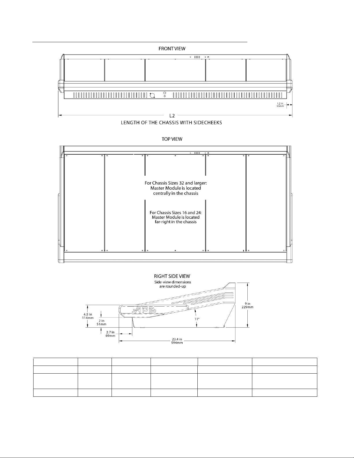
Console Dimensions
ProDesk-4 OWNER’S MANUAL
Chassis Size > 16-Chan 24-Chan 32-Chan 40-Chan 48-Chan
Module Order Inp•Inp•Mstr Inp•Inp•Inp•Mstr Inp•Inp•Mstr•Inp•Inp Inp•Inp•Inp•Mstr•Inp•Inp Inp•Inp•Inp•Mstr•Inp•Inp•Inp
Length (L2) Inchmm30.72in
780.3mm
38.82in
986.1mm
46.92in
1191.8mm
55.02in
1397.5mm
63.12in
1603.3mm
Weight-lbs (kg) 90 (41) 100 (46) 115 (53) 130 (59) 145 (66)
Contact APB or check our website for detailed chassis drawings for roadcase construction or installation dimensions
37
Page 38

TECHNICAL SPECIFICATIONS
All measurements ref to 20Hz to 20KHz BW unless otherwise noted
Frequency Response (any input to any output) +0 / -0.5dB 10Hz to 50kHz (ref to 1kHz)
THD + Noise (Mic Input to Main Output) < 0.01% @ +15dBu output
Phase Response (Mic Input to Main Output) +10/-15 degrees 20Hz to 20kHz (ref to 1kHz)
Noise
Mic EIN -128dBu @ 60dB gain, 150Ω source
Main Bus (L-R-C-M) or Group Output Noise -82dBu (32 channels routed w/faders down, Master fader at unity)
Aux Bus Output Noise -90dBu (Aux sends down, Aux Master level at unity)
Matrix Output Noise -85dBu (Sends down, Matrix Level at unity)
Crosstalk (measured at 1KHz)
Channel Mute >100dB
Channel Fader Attenuation >100dB
Channel Routing >80dB
Channel Pan Isolation >80dB
Channel to Channel Isolation >90dB
Aux Send Attenuation >90dB
Aux Pan Isolation >70dB
Input / Output Impedances
Channel XLR Input >3KΩ Balanced (with or without Pad)
Channel Line Input (via TRS) >20KΩ Balanced
Channel Line Input (via XLR w/Pad) >4KΩ Balanced
Channel TRS Direct Out 100Ω Impedance Balanced
Bus XLR Outputs (Main, Group, Aux, Matrix) 50Ω Balanced using OutSmarts driver chip
Channel and Bus Insert Sends/Returns 100Ω Unbalanced / 5KΩ Unbalanced
Monitor TRS Outputs 100Ω Impedance Balanced
Input / Output Levels
Channel Insert +4dBu • 1/4” TRS Tip= Send, Ring= Return, Sleeve= Chassis
Max Out= +22dBu
Channel Direct Out +4dBu • 1/4” TRS Impedance-Balanced, Tip= “Hot”
Max Out= +22dBu
Balanced Outs +4dBu • M-XLR Symmetrically-Balanced, Pin 2= “Hot”
Max Out= +28dBu
Bus Insert -2dBu • 1/4” TRS Tip= Send, Ring= Return, Sleeve= Chassis
Max Out= +22dBu
Page 39

ProDesk-4 OWNER’S MANUAL
39
Page 40

APB-DynaSonics • ProDesk-4 Owners Manual • Rev- 0.91 • July-2009
 Loading...