

Page 1
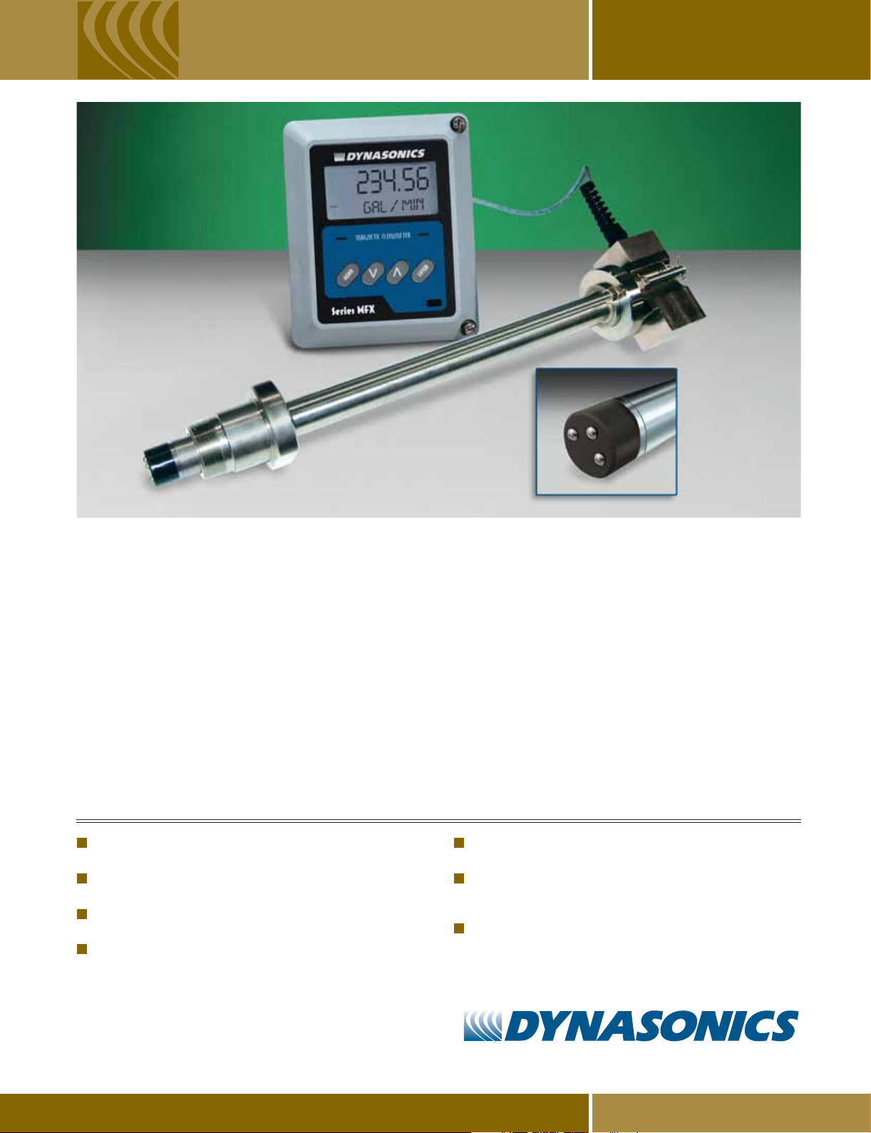
Series MFX
HOT-TAPPED INSERTION MAGNETIC PROBE
Series MFX Insertion MagProbe™ Flow Meters feature the world’s
most advanced magnetic flow measurement technology. The Series
MFX is a cost-effective solution for accurate measurement of
conductive liquid in closed conduit, pressurized-pipes without
process shutdown. The "flat tip" design will reduce fouling in
applications where suspended solids are present.
The MFX reliably measures most conductive fluids including water,
sewage, wastewater, clarified water, RAS, WAS, primary sludge and
cooling tower water, as long as adequate lengths of straight pipe are
available where the sensor is installed.
The MFX system consists of a hot-tappable insertion-type sensor that
mounts through a 1-1/2” ball valve pipe-tap into the flowing liquid,
and a remote digital display enclosure. The digital display is utilized to
FEATURES
Absolute (bi-directional) measurements from 0.1 to 30 FPS
(0.03 to 9 MPS).
Integrated sensor pre-amplifier permits separation of up to 990 feet
(297 m) between the sensor probe and MFX electronic analyzer.
Optional, optically isolated, field replaceable input/output modules
include: 4-20mA, dual-relay, rate pulse, RS232 and RS485.
Hot-tap sensor can be installed and retracted from process piping
without draining or depressurizing the system.
program engineering units, view flow rate/totalizer values and provide
process outputs. Velocity and pipe diameter information are entered by
the user via the display keypad or UltraLink™ software and used to
calculate volumetric flow, over wide flow ranges, with a high degree
of accuracy.
The Series MFX is more versatile and convenient than most
conventional full-pipe magnetic meters. MFX meters can be universally applied to a large range of pipe sizes without hardware changes,
compared to the specific internal pipe dimension design of conventional magnetic meters. In addition, cost differences are minimal when
moving to larger pipe sizes.
MagProbe sensors are available in
limited access mounting configura
diameters 4 to 120 inches (102 to 3048 mm).
High impedance input circuits minimize the influence of
electrode coating.
Industrial-grade sensor design: NEMA 6 (IP 67) submersible,
temperature to +225 °F (+105 °C), pressure to 700 PSIG (48 bar), titanium,
316SS, Viton
UltraLink PC utility permits configuration and intelligent diagnostics
to be performed.
®
and PVDF wetted materials.
various lengths to accommodate
tions and installation in pipe internal
DIVISION OF RACINE FEDERATED INC.
www.dynasonics.com800.535.3569
TM
Page 2
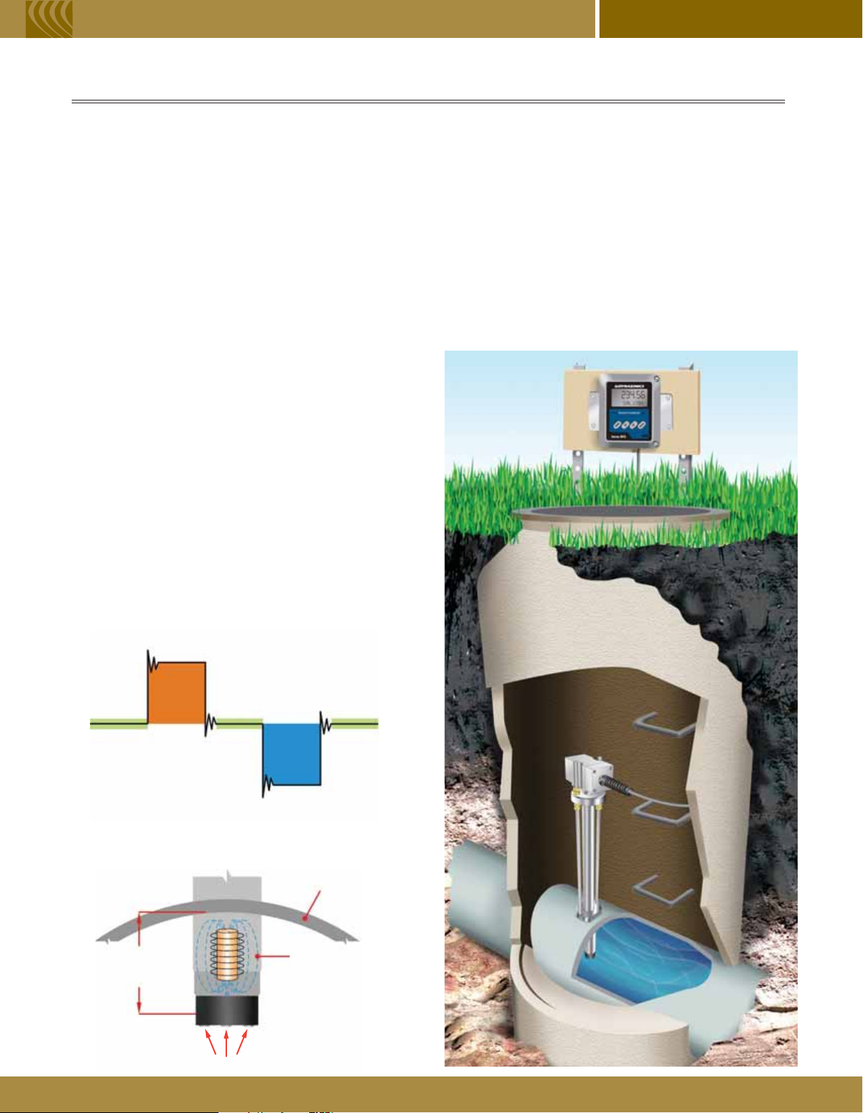
PRINCIPLES OF OPERATION
Series MFX Series MFX Series MFX
™
The MagProbe
used for measuring electrically conductive liquids, such
as water and water-based fluids, in closed piping
systems. The unit operates utilizing Faraday’s principle
of magnetic conduction, whereby a moving conductor
(the liquid) has a voltage imposed on it that is directly
proportional to two variables – the strength of a local
magnetic field and the velocity of the moving conductor.
Imposed voltage α Magnetic field × Fluid velocity
If the strength of the magnetic field is held constant,
then the magnitude of the voltage will be proportional to
the velocity of the moving conductor. The equation then
simplifies to Imposed voltage α Fluid velocity. The
MFX applies tri-stated, alternating polarity DC pulses to
an integral electromagnet (See Figure 1). Voltage
measurements are made with the magnet off, to
measure ambient background noise, and then with the
magnet on in both polarities. The magnitude difference
in voltage measured is proportional to flow. Once fluid
velocity is measured, then various volumetric flow
measurements will be obtained if the pipe internal
diameter (I.D.) is known.
Point-velocity flow meters measure the fluid velocity at a
specified depth into the fluid stream, typically 1/8 of the
pipe I.D., which has been proven to be the nominal
velocity point when symmetrical flow profiles are
present. This assumption requires the probe to be
downstream of any piping condition (elbows, valves,
thermo-wells, tees, etc.) that can cause flow
Typically, a minimum of 15 pipe diameters of straight
pipe is required to develop a symmetrical flow profile.
is a point-velocity measuring device
abnormalities.
The MFX is the perfect alternative to clamp-on and inline style
flow meters where pipe construction and site accessibility may
present an installation problem. Dynasonics’ “hot-tap” design
makes installation of the MagProbe sensor possible without
having to plumb in or drain a line.
A typical application would find the MagProbe installed on a pipe
inside a vault or manhole (See Figure 3), measuring the flow of
water or wastewater. The NEMA 4X enclosure rating of the MFX
transmitter gives the added flexibility of indoor or outdoor usage.
The MFX is best suited for measuring clean liquids on large
pipes with large amounts of straight run.
Figure 3 – Typical MagProbe Water Application
Figure 1 – Magnet Excitation
Magnet On
+ Polarity
Magnet
Off
Figure 2 – MagProbe Design
1/8 of Pipe
Diameter
Magnet
Off
Magnet
Off
Magnet On
- Polarity
Pipe Wall
Pulsed
Magnetic
Field
Electrodes
Page 3

S
PECIFICATIONS
T
RANSMITTER
DESCRIPTION SPECIFICATION
Power Requirements 115/230 VAC 50/60 Hz ± 15% @ 5 VA max.; 9-28 VDC @ 3 VA max.
Velocity Range -30 to +30 FPS (-9 to +9 MPS); minimum flow 0.1 FPS (0.03 MPS)
Inputs/Outputs All modules are optically isolated from earth and system grounds.
Only one module may be installed.
Optional 4-20 mA Output 800 Ohms max.; 12-bit resolution; internal or external power; can be spanned anywhere
in the velocity range
Relay two separate Form C relays, 200 VAC @ 0.5 A resistive max.
Rate Pulse 0-2,500 Hz; 0.21 Ohm resistance; 1 A max.; can be spanned anywhere in the velocity range
RS232C data rate to 57.6K
RS485 supports up to 126 drops on three wires; 57.6K max. baud; Communications protocol
Data Logger 200,000 point, 16-bit resolution; integral DB-9 connector for plugging into PC;
can be removed and installed without disconnecting system power
Display 2-line x 8-character LCD, back lit. Top row: 7-segment digit height 0.7 inches (18 mm),
Bottom row: 14-segment digit height 0.35 inches (9 mm); 8-digit rate, 8-digit totalizer (resettable)
Units:
Engineering units Feet, gallons, cubic feet, mil-gal, barrels, acre-feet, lbs., meters, cubic meters, mil-liters, kg
Rate time intervals Seconds, minutes, hours and days
Temperature Range -40 ° to +185 °F (-40 ° to +85 °C), 0-95% relative humidity, non-condensing
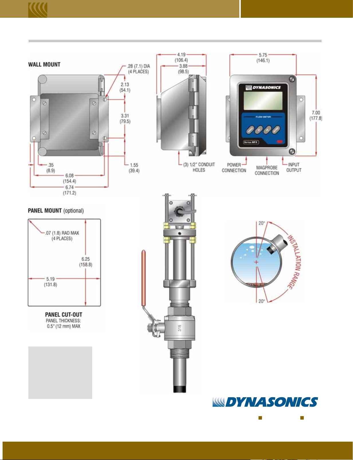
Enclosure NEMA 4X (IP-65), polycarbonate, SS, brass and plated steel. 7.00H × 5.75W × 3.88D inches (178H × 146W × 99D mm)
Accuracy Flow Rate ±2% of full scale
Sensitivity ±0.005 FPS (±0.0017 MPS)
Response Time 3-300 seconds, user configured, to 100% of value, step change in flow.
Security Keypad lockout, access code enable
Approvals (Std) Ordinary area
User configured
P
ROBE
DESCRIPTION SPECIFICATION
Pipe Sizes Internal diameters 4 to 120 inches (102 to 3048 mm); requires 11/2" NPT port
Liquid Requirements Liquids with conductivity > 1 micro-Siemen/cm; liquids with solids that will not coat or wrap around the probe tip
Transmitter to Up to 990 feet (297 meters)
Probe Distance
Environment
Materials of Construction 316 Stainless Steel, PVDF, Viton
Electrodes: Titanium
Operating Pressure
-40 ° to +225 °F (-40 ° to +105 °C), NEMA 6 (IP67) submersible
®
, PVC jacketed cable rated for outdoor and direct-burial use
Up to 700 PSIG (48 bar) max. @ +75 °F (+25 °C)
Page 4

MAGPROBE
Seal Fitting
1-1/2" Full Flow
Ball Valve
1-1/2" NPT
Thread-O-Let
™
SELECTION
MagProbe
Diameter
Seal Fitting
Valve Stack
Pipe Wall
1/8 of Pipe
Diameter
Probe Length Selection Procedure
Before purchasing a MagProbe insertion flow
meter, it is necessary to calculate the probe length
required for a particular piping system. In order to
complete this calculation, some knowledge of the
piping system must be known. The variables
required are:
Pipe internal diameter
Pipe wall thickness
The length of the valve stack
Amount of straight pipe diameters in the system
Using this information and referring to the picture
to the left, a minimum probe length can be
determined.
Measurement A – The typical depth that the
MagProbe tip is inserted into the piping system is
1/8 of the pipe internal diameter. Assume 1/8 of the
pipe internal diameter unless a system piping
configuration does not have at least 15 pipe
diameters of straight pipe in the installation area.
In that case, assume 1/2 of the pipe internal
diameter – this will allow for flow profiling to
be performed.
Measurement B – Pipe wall thickness. This
information can be obtained from standard pipe
wall charts or, ideally, can be measured using an
ultrasonic wall thickness gauge.
Measurement C – Estimate the height that is
going to be taken up by the pipe tap, nipple and
full-flow ball valve. DMP2 through DMP5 probes
1
utilize 1
Measurement D – The insertion fitting for DMP2
through DMP5 probes is 2.5 inches.
Minimum Probe Length Required = A+B+C+D
/2" NPT hardware.
TRANSMITTER PART NUMBER MATR I X
D M F X N
Transmitter Type
2) Rate and Totalizer
Power Supply
A) 115 VAC
B) 230 VAC
C) 100 VAC
E) 9-28 VDC
Input/Output 1
N) None
1) 4-20 mA Output
2) Relay
3) Rate Pulse
4) RS232C
5) RS485
6) Data Logger
2
Input/Output 2
N) Reserved
Totalizer
A) Eight Digit Resettable
A
NN
Options
N) None
Approvals
N) Ordinary Area
MAGPROBE PART NUMBER MATR I X
D M P
Probe Length
2) 18 inches (457 mm)
3) 28 inches (711 mm)
4) 38 inches (965 mm)
5) 48 inches (1220 mm)
*Consult Factory for Longer Lengths
Cable Length
020) 20 feet (6 m)
050) 50 feet (15 m)
100) 100 feet (30 m)
Maximum Length: 990 feet (297 m)
in 10 ft. (3 m) increments
Conduit Type**
N) None
Conduit Length**
000) 0 feet (0 m)
**Consult the Dynasonics factory for
conduit availability and part numbers.
Options
N) None
B) 1.5 inch
150# RF
flange
connection
316SS
Page 5

ISO-MOD INPUT/OUTPUT MODULES DIMENSIONAL
General
ISO-MODs are epoxy-encapsulated electronic output
modules that are simple to install and replace in the field.
All modules are 2500 V optically isolated from MFX
power and earth grounds – eliminating the potential for
ground loops and reducing the chance of severe
damage in the event of an electrical surge. Six ISO-MOD
options are available including: 4-20 mA output,
dual-relay, rate pulse, RS232C, RS485 and 200K-point
data logger. All modules are field-configurable by utilizing
the front keypad. Field wiring connections to ISO-MODs
are quick and easy using pluggable terminals. Features
of the various ISO-MODs are described below.
4-20 mA Output Module
Easily configured via jumper selections into either an
internally-powered or externally-powered mode, the
4-20 mA Output Module interfaces with virtually all
recording and logging systems by transmitting an
analog current signal that is proportional to system flow
rate. Independent 4 mA and 20 mA span settings are
established in software. These settings can span
negative and positive flow directions to output
bi-directional flow data. These entries can be set
anywhere in the -30 to +30 FPS (-9 to +9 MPS)
measuring range of the instrument. Output resolution of
the module is 12-bits (4096 discrete points) and
because of its low insertion loss characteristics (less
than 5 V typical), the module can drive up to 800 ohms
of load with a 24 V power source.
Rate Pulse Output Module
The Rate Pulse Output Module is utilized to transmit
information to external counters and PID systems via
a frequency output that is proportional to system
flow rate. Independent Zero and Span settings are
established in software. These entries can be set
anywhere in the -30 to +30 FPS (-9 to +9 MPS)
measuring range of the instrument. Output resolution
of the module is 12-bits (4096 discrete points) and the
maximum output frequency setting is 2500 Hz.
RS485 Input/Output Module
The RS485 Module allows up to 126 MFX systems to be
placed on a single three-wire cable network. All meters
are assigned a unique serial number that allows all of
the meters on the cable network to be accessed
independently. Baud rates up to 57.6K and cable
lengths to 5,000 feet (1,500 meters) are supported.
Control Relay Module
Two independent SPDT (single-pole, double-throw,
Form C) relays are contained in this module. The relay
operations are user configured via software to act in
either a flow rate alarm, system diagnostic alarm or
totalizer/batching mode. The relays are rated for 200
VAC max. and have a current rating of 0.5A resistive
load (175 VDC @ 0.25 A resistive). It is highly
recommended that a secondary relay be utilized
whenever the Control Relay ISO-MOD is used to control
inductive loads such as solenoids and motors.
Data Logger Module
This powerful 200,000-point data logger/electronic
stripchart recorder configures to match user
The logger stores time-stamped, high resolution (16-bit)
data at user-selected intervals ranging from 1 to 1,000
seconds. Configuration of and data retrieval from the
logger can be accomplished in one of two ways:
applications.
Two electronic outputs are integrated into the module –
an open-drain MOSFET and a turbine meter simulated
type. The MOSFET has an ON resistance of 0.21 Ohms
and is rated at 1 A and 100 V. The turbine simulation
permits the instrument to transmit information to
devices configured for magnetic turbine and
paddle-wheel flow meter pickups.
RS232C Input/Output Module
The RS232C Module can be interfaced with serial
communication ports of PCs, PLCs and SCADA
systems, running a Modbus protocol, that are used to
monitor flow rate information in piping systems. Baud
rates up to 57.6K are supported.
The module can be carried back to the office and
plugged into a serial port on a PC via the module’s
integral DB9 connector. This feature eliminates the
need to carry a laptop computer to the flow
meter site.
A hardwire connection can be made to the data
logger module which allows direct interface to the
serial communication port of a PC, PLC or SCADA
system. Historical data can be uploaded via the
supplied Windows® software utility.
Page 6
S
PECIFICATIONS
MECHANICAL DIMENSIONS: INCHES (mm)
Series MFXSeries MFX
MODEL LENGTH (L)
DMP 2
DMP 3
DMP 4
DMP 5
28.82 (732)
38.82 (986)
48.82 (1240)
58.82 (1494)
HEAD-ON VIEW
OF PIPE
INSTALL MAGPROBE
BETWEEN 1 0’CLOCK
AND 5 0’CLOCK ON THE PIPE
TM
Dynasonics, MagProbe and UltraLink are trademarks of Racine Federated Inc.
Viton is a registered trademark of DuPont Dow Elastomers
Windows is a registered trademark of Microsoft Corp.
FORM MFX 3/07
DIVISION OF RACINE FEDERATED INC.
8635 Washington Ave. Racine, WI 53406 USA
Tel: 262.639.6770
Fax: 262.639.2267
www.dynasonics.com
800.535.3569 North America
800.732.8354 North America
 Loading...