

Page 1

Series MFX
Insertion MagProbe™ Flow Meter
Operations & Maintenance
Manual
REV 2/08
Page 2

TABLE OF CONTENTS
Pages
Part 1 -
Introduction
Part 1 -
Installation
Quick-Start Operating Instructions
Introduction
General
Applications
Model Matrix
Product Specifications
Installation
Transmitter Installation
MagProbe Connection
Transmitter Power Connections
1.3-1.4
1.5
1.6
1.7-1.8
1.9
1.10-1.12
1.12
1.12-1.15
Part 1
ISO-MOD
Part 2 - Probe
ISO-MOD Wiring and Configuration
4-20mA Output
Dual Control Relay
Rate Pulse Output
RS232C
RS485
DATALOGGER
Instrument Startup
MagProbe Installation
1.17
1.18
1.19
1.20
1.21
1.22
1.23
2.1-2.9
Installation
MagProbe Insertion/Retraction
Rev. 2/2008 -1.1- MFX
2.9
Page 3

TABLE OF CONTENTS
TABLE OF CONTENTS
Pages
Part 3 - Keypad Configuration
Part 4 - Software Utilities
Programming Entries
Keypad Operation
BASIC MENU
OUTPUT MENU
SECURITY MENU
SERVICE MENU
DISPLAY MENU
Installation
Initialization
Configuration
Pipe & Liquid
Flow Units
Outputs
3.1-3.2
3.3-3.7
3.8-3.15
3.15-3.16
3.16-3.18
3.18-3.19
4.1
4.2
4.3
4.4
4.6-4.13
Setting Zero
Signal Quality
Data Logger Software
Appendix
Keypad Interface Map
Digital Communications Protocol
Pipe Dimension Chart: Cast Iron
Pipe Dimension Chart: ST, SS, PVC
Pipe Dimension Chart: Ductile Iron
Velocity to Volumetric Conversion
Statement of Warranty
Rev. 2/2008 -1.2- MFX
Customer Service
4.13
4.15
4.17-4.19
Page 4
QUICK-START OPERATING INSTRUCTIONS
MagProbe
Location
Top of Pipe
This manual contains detailed operating instructions for all aspects
of the MFX instrument. The following condensed instructions are
provided to assist the operator in getting the instrument started up
and running as quickly as possible. This pertains to basic operation only. If specific instrument features are to be used or if the installer is unfamiliar with this type of instrument, refer to the appropriate section in the manual for complete details.
1. SELECT THE MAGPROBE LOCATION
A. In general, select a mounting location on the piping system
with a minimum of 10 pipe diameters (10 X the pipe inside
diameter) of straight pipe upstream and 5 straight diameters
downstream. See Table 2.1 for additional configurations.
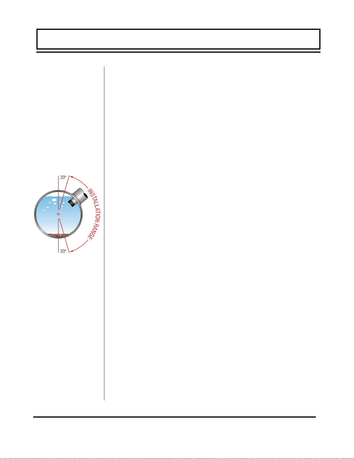
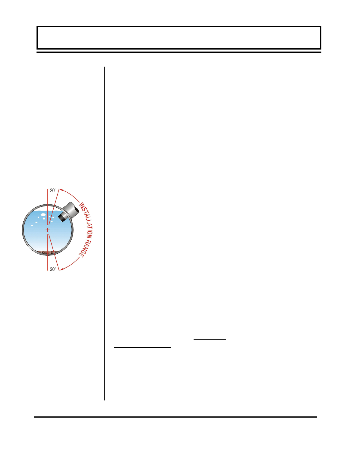
B. When the probe is installed on a horizontal pipe, the pre-
ferred orientation for the probe is between 1 and 5 o’clock
as shown in Figure 1.1. Ensure that the probe is installed
square and centered on the pipe.
2. HOT TAP CONFIGURATION
A. Verify that all components being permanently installed or
used during the installation procedure are rated for operation at the greatest system pressure anticipated.
Figure 1.1
Inserting
MagProbe
B. Mount the pipe saddle or weld fitting at the location deter-
mined in step 1. Install the close nipple and ball valve. Drill
a hole in the pipe that is at least 1/8” [3 mm] larger than the
MagProbe tip. Close the ball valve.
C. Install the MagProbe insertion fitting.
3. INSERT THE MAGPROBE INTO THE PIPE
A. To obtain greatest accuracy, the measuring tip of the Mag-
Probe must be inserted a proper distance into the pipe. For
long, straight runs of pipe, this is 12.5% of the pipe internal
diameter.
B. Before inserting the MagProbe into the insertion fitting, it is
best to make all of the necessary measurements on the
probe and installation fittings and place a insertion depth
mark on the probe.
C. Measure the full length of the probe (E), calculate 12.5% of
the pipe I.D. (A), obtain the pipe wall thickness (B) and
measure the distance between the outer pipe wall and the
Rev. 2/2008 -1.3- MFX
Page 5
RED
WHITE
BLUE
BLACK
BROWN
GREEN/SHIELD
QUICK-START OPERATING INSTRUCTIONS
QUICK-START OPERATING INSTRUCTIONS
top of the insertion fitting (C).
D. Place a mark on the probe this is the proper distance from
the top of the probe (D):
D = E - A - B - C
D020-1050-010
SHIELD
TO SENSOR
POWER
TERMINAL
Figure 1.2
Connections
E. Insert the MagProbe into the insertion fitting and secure with
DATA
DCLK
SCLK
Ø V
+24 V
the brass lock nuts—Series DMP2 - DMP6.
F. Open the ball valve and insert the probe to the distance
marked in step D. Secure with the brass nuts.
G. Rotate the probe in the pipe so that the FLOW DIRECTION
arrow points in the nominal forward flow direction (the MFX
system will read flow in both directions) and to within ±2° of
parallel to the pipe length.
4. ELECTRICAL CONNECTIONS
Run the MagProbe cables back to the MFX transmitter mounting
location. Connect the MagProbe and power to the appropriate terminal connections within the MFX enclosure. See Figure 1.2.
A. Do not run the probe cable adjacent to electrically noisy wir-
ing.
B. Verify that the MFX is configured for the power supply that
will be utilized in the installation. Run power through the left
hand conduit hole and secure to the proper terminals.
C. Connect a 12 AWG (minimum) ground wire between the
ground lug on the MagProbe seal fitting and earth ground.
Startup
5. INITIAL SETTINGS AND POWER UP
A. Apply power to the instrument.
B. Verify that fluid velocity is indicated on the top line of the
MFX display.
C. Input proper units of measure and I/O data.
Rev. 2/2008 -1.4- MFX
Page 6
General
PART 1 - INTRODUCTION
The MagProbe is a point-velocity measuring device used primarily
for measuring electrically conductive liquids, such as water and
water-based liquids, in closed piping systems. The unit operates
utilizing Faraday’s principle of magnetic conduction, whereby a
moving conductor (the liquid) has a voltage imposed on it that is
directly proportional to two variables — the strength of a local
magnetic field and the velocity of the moving conductor.
Imposed voltage α Magnetic field X Fluid velocity
If the strength of the magnetic field is held constant, then the magnitude of the voltage will be proportional to the velocity of the moving conductor. The equation then simplifies to Imposed voltage α
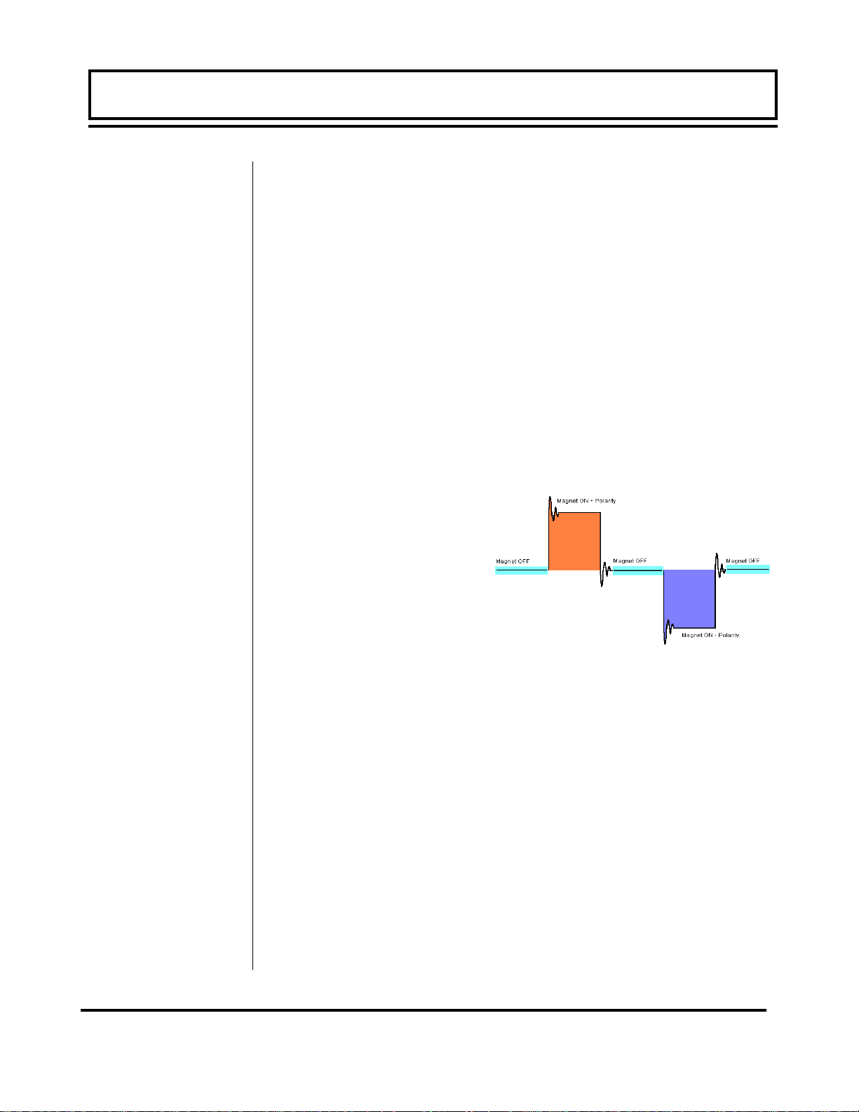
Fluid velocity. Most modern magnetic meters, including the MFX,
apply tri-stated, alternating polarity DC pulses to an integral electromagnet. See Figure 1.3. Voltage measurements are made
with the magnet off, to measure ambient background noise, and
then with the magnet on in both polarities. The magnitude difference in voltage measured
is proportional to flow.
Once fluid velocity is
measured, then various
volumetric flow measurements can be obtained if
the pipe internal diameter
(I.D.) is known.
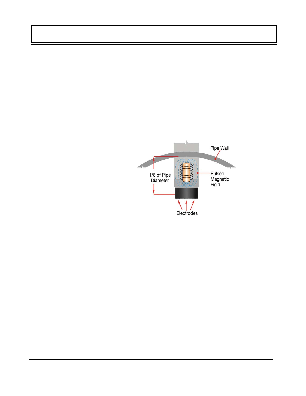
Point-velocity flow meters
measure the fluid velocity
at a specified depth into
the fluid stream, typically 1/8 of the pipe I.D., which has been
proven to be the nominal velocity point when symmetrical flow profiles are present. This assumption requires the probe to be certain
numbers of pipe diameter downstream of any piping condition
(elbows, valves, thermo-wells, tees, etc.) that can cause flow abnormalities. Typically, a minimum of 15 pipe diameters of straight
pipe is required to develop a symmetrical flow profile. Systems
where symmetrical flow profiles are not present can still be measured accurately, but flow profiling must be performed to determine
proper probe insertion depth. A diagram of the MagProbe tip is
illustrated in Figure 1.4.
Rev. 2/2008 -1.5- MFX
Figure 1.3 - Magnet Excitation
Page 7
PART 1 - INTRODUCTION
PART 1 - INTRODUCTION
The MFX MagProbe flow meter can be successfully applied on a
wide range of metering applications. The simple to program transmitter allows the standard product to be used on pipe sizes ranging from 4 - 120 inch [ 100 - 3048 mm ] pipe. A variety of liquid
applications can be accommodated: potable water, chemicals,
raw sewage, reclaimed water, cooling water, river water, plant effluent, etc. The MFX product will not operate on fluids with very
high impedance such as DI water, distilled water, petroleum-based
liquids or glycol-based liquids.
Figure 1.4 - MagProbe Design
Rev. 2/2008 -1.6- MFX
Page 8
PART 1 - INTRODUCTION
PART 1 - INTRODUCTION
User Safety
Data Integrity
Product
Identification
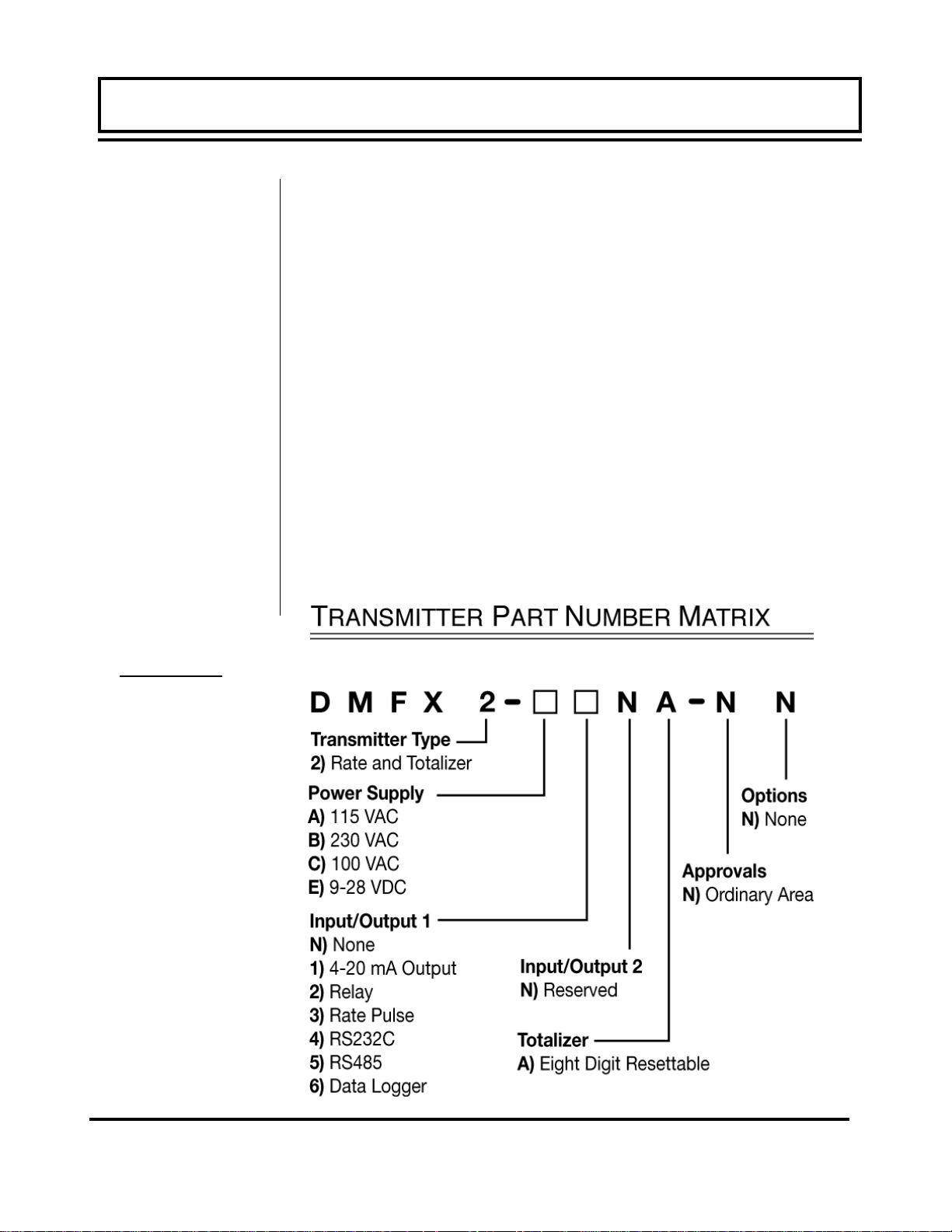
Product Matrix
The MFX employs modular construction and provides electrical
safety for the operator. The display face contains voltages no
greater than 10 Vdc. The display face swings open to allow access to user connections. As a general precaution, always disconnect electrical power before opening the instrument enclosure.
Non-volatile memory retains all user-entered configuration values in memory even if power is lost or turned off. Password protection is provided as part of the Security menu and prevents inadvertent configuration changes or totalizer resets.
The serial number and complete model number of your MFX and
the DMP probe that was shipped with the MFX is located on the
inside of the transmitter’s front cover. Should technical assistance be required, please provide the Dynasonics Customer
Service Department with this information.
Transmitter
Rev. 2/2008 -1.7- MFX
Page 9
PART 1 - INTRODUCTION
PART 1 - INTRODUCTION
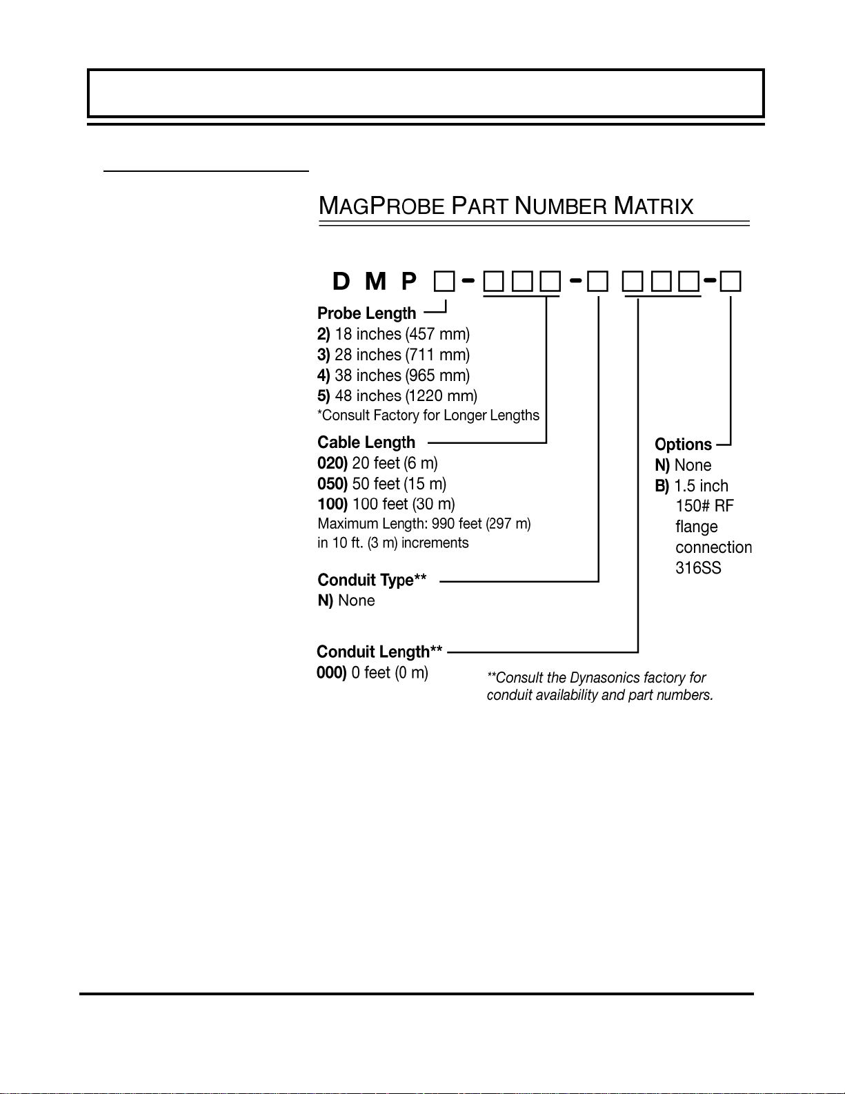
MagProbe Insertion Probe
Rev. 2/2008 -1.8- MFX
Page 10

Transmitter MagProbe
PART 1 - SPECIFICATIONS
Rev. 2/2008 -1.9- MFX
Page 11

PART 1 - TRANSMITTER INSTALLATION
Transmitter
Installation
After unpacking, it is recommended to save the shipping carton
and packing materials in case the instrument is stored or reshipped. Inspect the equipment and carton for damage. If there
is evidence of shipping damage, notify the carrier immediately.
The enclosure should be mounted in an area that is convenient
for servicing, calibration or for observation of the LCD readout.
1. Locate the transmitter within the length of MagProbe cable
that was supplied with the MFX system. If this is not possible,
replace the entire length of interconnect cable with Belden
part number 9536, Dynasonics part number D005-1003-003
or equivalent. Do not splice the cable as shield integrity will
be compromised and poor performance can result.
2. Mount the MFX transmitter in a location that is:
♦ Where little vibration exists.
♦ Protected from falling corrosive fluids.
♦ Within ambient temperature limits -40 to 185°F [-40 to 85°C]
♦ Out of direct sunlight. Direct sunlight may increase tempera-
tures within the transmitter to above maximum limit.
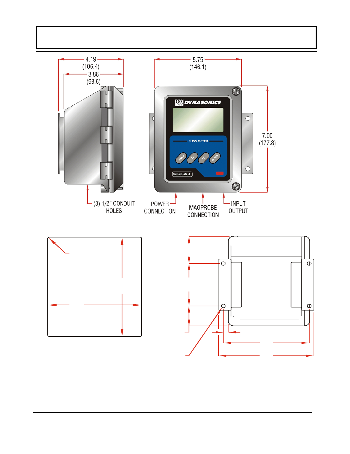
3. Mounting: Refer to Figure 1.5 for enclosure and mounting
dimension details. Ensure that enough room is available to
allow for door swing, maintenance and conduit entrances.
Secure the enclosure to a flat surface with four appropriate
fasteners.
4. Conduit holes. Conduit hubs should be used where cables
enter the enclosure. Holes not used for cable entry should be
sealed with plugs.
NOTE: Use NEMA 4X [ IP66 ] rated fittings/plugs to maintain the
water tight integrity of the enclosure. Generally, the left conduit
hole (viewed from front) is used for line power; the center conduit
hole for transducer connections and the right hole is utilized for
ISO-MOD I/O wiring.
Rev. 2/2008 -1.10- MFX
Page 12
PART 1 - TRANSMITTER INSTALLATION
T
PART 1 - TRANSMITTER INSTALLATION
PAN EL M O UNT
.07 (1.8) RAD MAX
(4 PLACES)
5.19
(131.8)
PAN EL C UT-OUT
P ANEL THICKNESS: 0.5”
(12 mm) MAX
Figure 1.5 - MFX Transmitter Installation Dimensions
(optional)
6.25
(158.8)
1.55
(39.4)
.28 (7.1) DIA
(4 PLACES)
WALL M O UN
2.13
(54.1)
3.31
(79.5)
.35
(8.9)
6.08
(154.4)
6.74
(171.2)
Rev. 2/2008 -1.11- MFX
Page 13
PART 1 - TRANSMITTER INSTALLATION
PART 1 - TRANSMITTER INSTALLATION
MagProbe
Connections
RED
WHITE
BLUE
BLACK
BROWN
GREEN/SHIELD
D020-1050-010
SHIELD
DATA
DCLK
TO SENSOR
POWER
Figure 1.6
Transmitter AC
Power
Connections
TERMINAL
5. If additional holes are required, drill the appropriate size hole in
the enclosure’s bottom or side. Use extreme care not to run the
drill bit into the wiring or circuits cards.
To access terminal strips for electronic connectors, loosen the two
screws in the enclosure door and open the door.
1. Guide the MagProbe terminations through the transmitter conduit hole located in the bottom-center of the enclosure. Secure
the MagProbe conduit with the supplied conduit nut if flexible
conduit was ordered with the transducer. If conduit was not purchased with the MagProbe sensor, an appropriate sealed strain
relief bulkhead fitting should be utilized.
2. The terminals within MFX are a pluggable type - they can be re-
SCLK
Ø V
+24 V
moved wired and then plugged back in. Connect the appropriate MagProbe wires to P1 (Sensor) at the corresponding screw
terminals on the MagProbe module. Observe proper wire colors
and shield connections. See Figure 1.6 or the Wiring Diagram
located on the inner door of the transmitter.
1. NOTE: The MagProbe cable carries low level signals. Locate
the transmitter within the length of MagProbe cable that was
supplied with the MFX system. If this is not possible, replace
the entire length of interconnect cable with Belden part number
9536, Dynasonics part number D005-1003-003 or equivalent.
Do not splice the cable as shield integrity will be compromised
and poor performance can result.
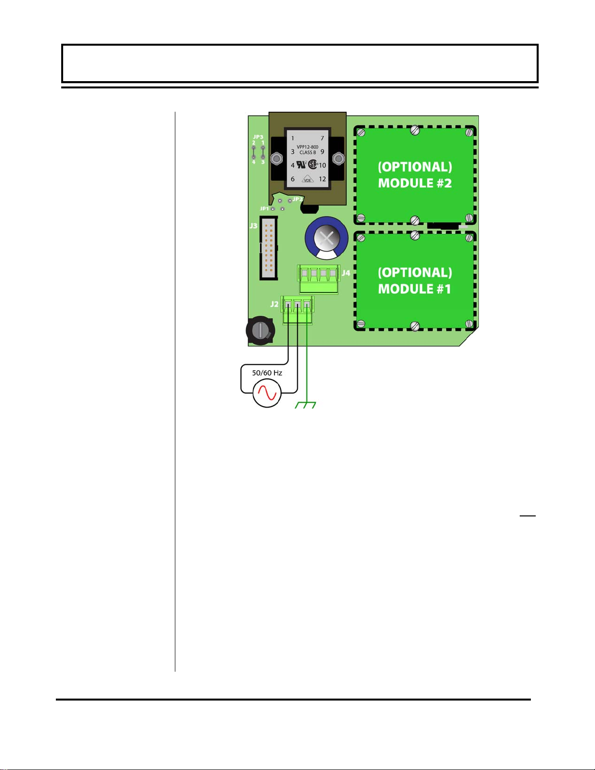
Connect line power to the screw terminals marked L1, L2 and Earth
in the transmitter. See Figure 1.7 and Figure 1.8. Utilize the conduit hole on the left side of the enclosure for this purpose. Use wiring practices that conform to local codes (National Electric Code
Hand book in the USA). The Earth ground terminal grounds the
instrument, which is mandatory for safe operation and optimum flow
meter performance.
CAUTION: Any other wiring method may be unsafe or cause improper operation of the instrument.
Rev. 2/2008 -1.12- MFX
Page 14

PART 1 - TRANSMITTER INSTALLATION
PART 1 - TRANSMITTER INSTALLATION
WIRING DIAGRAM
CAUTION! To avoid serious injury or
!
JP3
Connections
115 Vac
230 Vac
9-28 Vdc
JP1/JP2
Connections
115/230
Vac
9-28 Vdc
product damage, disconnect electrical power
before servicing this meter.
12 or 24 Vdc jumper
selection located on the
circuit board below this
decal.
1 2
16-28 Vdc JP1
9-16 Vdc
3 4
115/230 Vac
1 2
JP3
3 4
1 2
3 4
1 2
1
2
1 2
1
2
J3
1 2
3 4
JP2
JP1
2
J4
J2
JP2
1 2
1
No Connections
JP2
JP1
Bottom of circuit board
GREEN/SHIELD
L1
L2
EARTH
Optional
I/O Module
R41
MagProbe
Interface Module
BROWN
BLACK
BLUE
WHITE
Y1
RED
Fuse (5x20mm):
AC: 0.1A/250V Delay
DC: 0.5A/250V Delay
AC L1 L2 EARTH
DC +V GND EARTH
D003-0905-301 REV. B
Figure 1.7
MFX Power Supply Configuration
Do not run line power with other signal wires within the same wiring tray or conduit.
NOTE: This instrument requires clean electrical line power. Do
not operate this unit on circuits with noisy components (i.e. Fluorescent lights, relays, compressors, variable frequency drives,
etc.).
Rev. 2/2008 -1.13- MFX
Page 15
PART 1 - TRANSMITTER INSTALLATION
PART 1 - TRANSMITTER INSTALLATION
Figure 1.8
DC Power Connection
AC POWER CONNECTIONS
1. Verify that the jumpers at JP3 are properly oriented for the
power supply. Verify that the jumpers at JP1 and JP2 are not
present.
2. Connect L1, L2 and earth to the terminals referenced in Figure
1.7 on page 1.12. Phase and neutral connections to L1 and L2
are not polarized. Do not operate without an earth ground connection.
3. See Figure 1.8 for AC connection schematic. Wire gauges up
to 14 AWG can be accommodated in the MFX terminal blocks.
Rev. 2/2008 -1.14- MFX
Page 16
PART 1 - TRANSMITTER INSTALLATION
PART 1 - ISO-MOD
DC Power
Supply
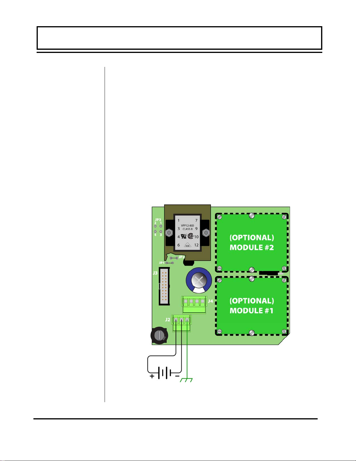
DC POWER CONNECTIONS
The MFX may be operated from a 9-28 Vdc source, as long as the
source is capable of supplying a minimum of 3 Watts.
1. Verify that the jumpers are properly placed. See the wiring diagram located on the inside door of the MFX enclosure or see
Figure 1.7 on page 1.12. The jumpers at JP3 should not be
present and the jumpers at JP1 and JP2 will be in place. The
jumper located beneath the microprocessor protection shield –
the panel with the wiring diagram label mounted on it – should
be positioned at JP2 for 9-16 Vdc input power and in JP1 position for 16-28 Vdc input power.
2. Connect the DC power source as illustrated in the schematic in
Figure 1.9. Wire up to 14 AWG can be accommodated in the
MFX terminal blocks.
Figure 1.9
Rev. 2/2008 -1.15- MFX
DC Power Connection
Page 17
PART 1 - ISO-MOD
General
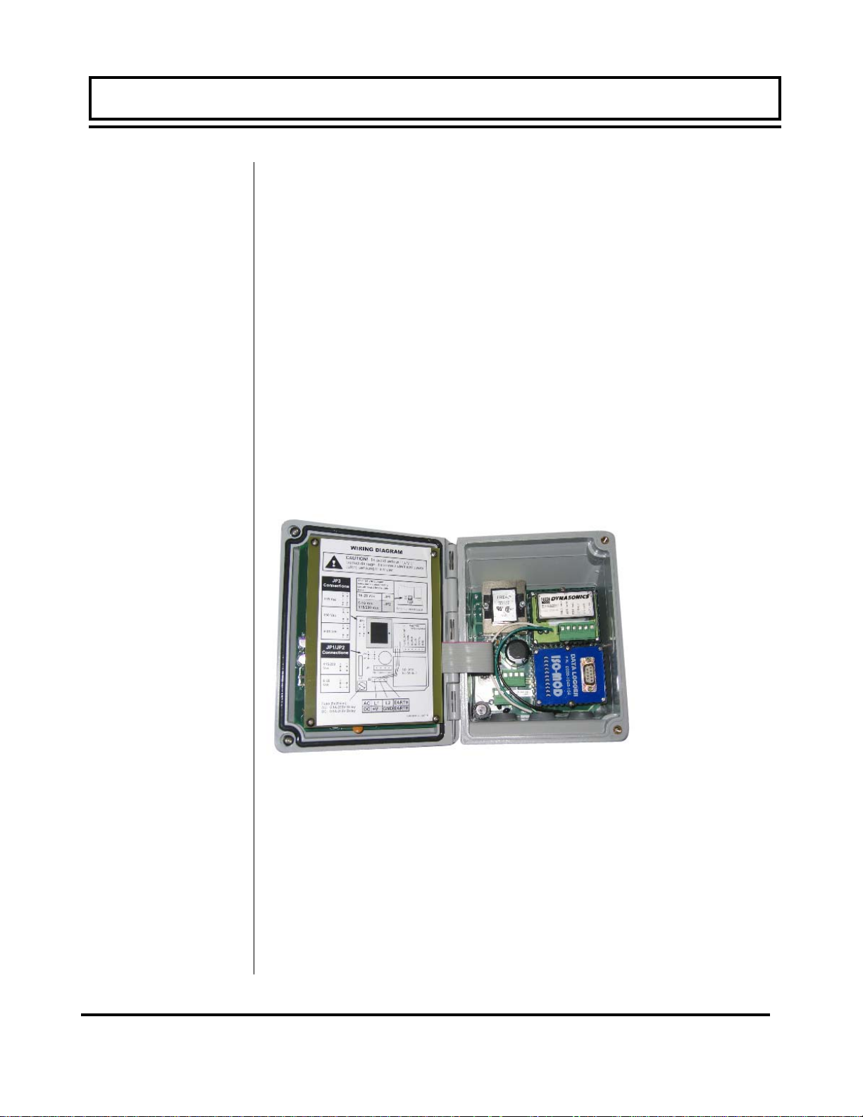
The TFXD utilizes ISO-MODs for input and output functions. ISOMODs are epoxy encapsulated electronic input/output modules
that are simple to install and replace in the field. See Figure 1.10.
All modules are 2,500 V optically isolated from TFXD power and
earth grounds. This eliminates the potential for ground loops and
reduces the chance of severe damage in the event of an electrical
surge.
Six ISO-MOD options are available, including: 4-20 mA, dual-relay,
rate pulse, RS232C, RS485, and 200k point data logger. The
MFX supports any of the six ISO-MOD input/output modules. All
modules are field configurable by utilizing the keyboard or
UltraLink
™
interface. Field wiring connections to ISO-MODs are
quick and easy using removable plug-in terminals. Configuration
and connection of the various ISO-MODs are described on the following pages.
Figure 1.10
Two ISO-MOD I/
O Modules
Installed
To remove an ISO-MOD, remove the two machine screws that
secure the module in place and pull the module straight out of the
enclosure. A 10-pin connection is on the bottom of the module
that mates with the circuit board underneath. Installation of a module is simply the reverse operation of removal. 4-20 mA modules will require calibration parameters to be entered if the module
is replaced. See Part 3 of this manual for instructions on entry of
calibration parameters.
Rev. 2/2008 -1.16- MFX
Page 18
PART 1 - ISO-MOD
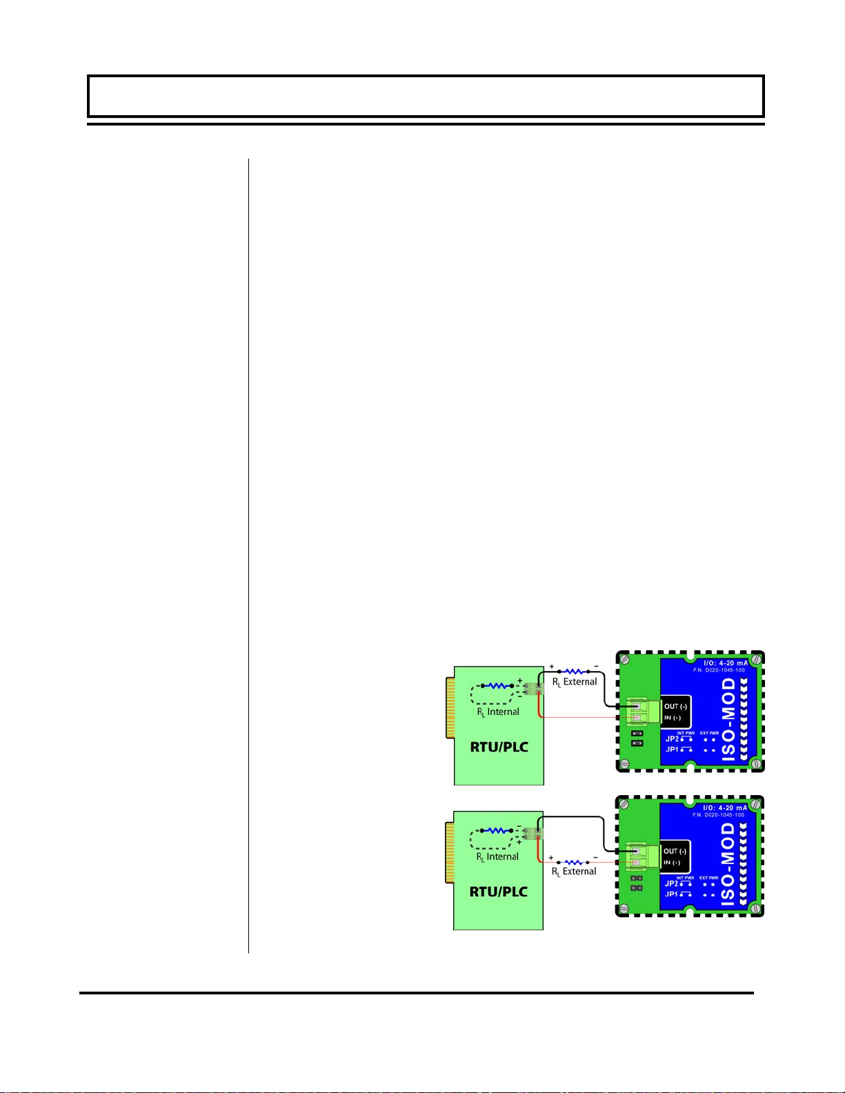
4-20 mA Output
The 4-20 mA Output Module interfaces with most recording and
logging systems by transmitting an analog current signal that is
proportional to system flow rate. The 4-20 mA ISO-MOD may be
configured via jumper selections for either an internally powered
mode (current sourcing) Figure 1.11A or externally powered mode
(current sinking) Figure 1.11B.
Internal Power Configuration: Ensure that jumpers are in place
at JP1 and JP2 on the module. See Figure 1.11A. In this configuration the 4-20 mA output is driven from a +24 Vdc source located within the MFX flow meter. The 24 Vdc source is isolated
from DC ground and earth ground connections within the MFX instrument. The module can accommodate loop loads up to 800
Ohms in this configuration.
External Power Configuration: Remove the two jumpers located
at JP1 and JP2 on the module. See Figure 1.7B. In this configuration the 4-20 mA module requires power from an external DC
power supply. The voltage of the external power source must be
sufficient to power the module and drive the loop load. The loop
loss attributed to the ISO-MOD is 7 Vdc, so the minimum voltage
required to power a loop can be calculated using the following formula:
Loop voltage (min) = (loop load Ohms x 0.02) + 7
Figure 1.11A
Internally Powered
4-20mA
Figure 1.11B
Externally Powered
4-20mA
Rev. 2/2008 -1.17- MFX
Page 19
PART 1 - ISO-MOD
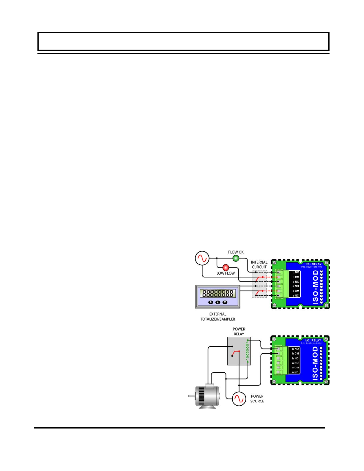
Control Relay
Two independent SPDT (single-pole, double-throw) Form C
relays are contained in this module. The relay operations are
user configured via software to act in either a flow rate alarm,
signal strength alarm or totalizer/batching mode. The relays are
rated for 200 Vac maximum and have a current rating of 0.5 A
resistive load [175 Vdc @ 0.25 A resistive]. It is highly
recommended that a secondary relay be utilized whenever the
Control Relay ISO-MOD is used to control inductive loads such as
solenoids and motors.
Typical relay connections are illustrated in Figure 1.12A. The
reed relays located within the relay module can interface directly
with small pilot lights, PLCs, electronic counters and SCADA systems.
Figure 1.12B describes the connection of an external power relay
to the Relay ISO-MOD. It is recommended that external power
relays are utilized whenever the load to be switched exceeds the
switch rating of the reed relays, or if the load is inductive in nature.
POWER
SOURCE
Figure 1.12A
Typical Relay
Connections
Figure 1.12B
Slave Relay
Connections
Rev. 2/2008 -1.18- MFX
Page 20
PART 1 - ISO-MOD
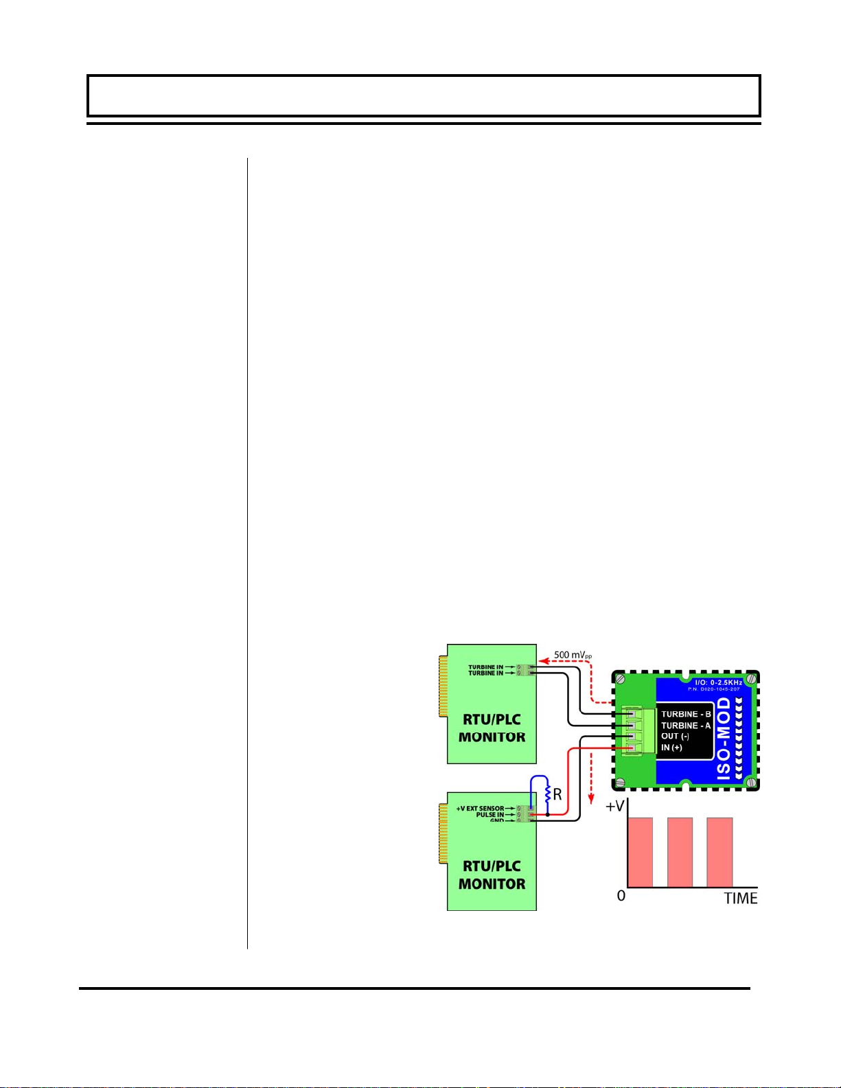
Rate Pulse
The Rate Pulse Output Module is utilized to transmit information to
external counters and PID systems via a frequency output that is
proportional to system flow rate. The frequency output range of
the Rate Pulse Module is 0–2,500 Hz. This module has two types
of outputs: one simulates the output of the coil of a turbine flow
meter, and the other is an open-collector type that does not source
voltage at its output. Both outputs may be connected simultaneously.
The turbine meter output creates a 500 mV peak-to-peak sawtooth waveform that is not referenced to ground. This output can
be run to electronic monitors that are compatible with variable reluctance outputs from coils, such as those found in turbine and
paddle-wheel flow meters. The input impedance of the receiving
device should not be smaller than 2,000 Ohms.
The standard pulse output does not output a voltage, but acts as
an “open-collector” output requiring an external power source and
pull-up resistor. See Figure 1.13. The MOSFET in the Rate
Pulse Module can support loads of 100 V @ 1A. Resistor selection is based on the input impedance of the receiving device. Select a resistor that is a maximum of 10% of the input impedance of
the receiving device, but do not exceed 10k Ohms.
Figure 1.13
Rate Pulse Module
Rev. 2/2008 -1.19- MFX
Page 21
PART 1 - ISO-MOD
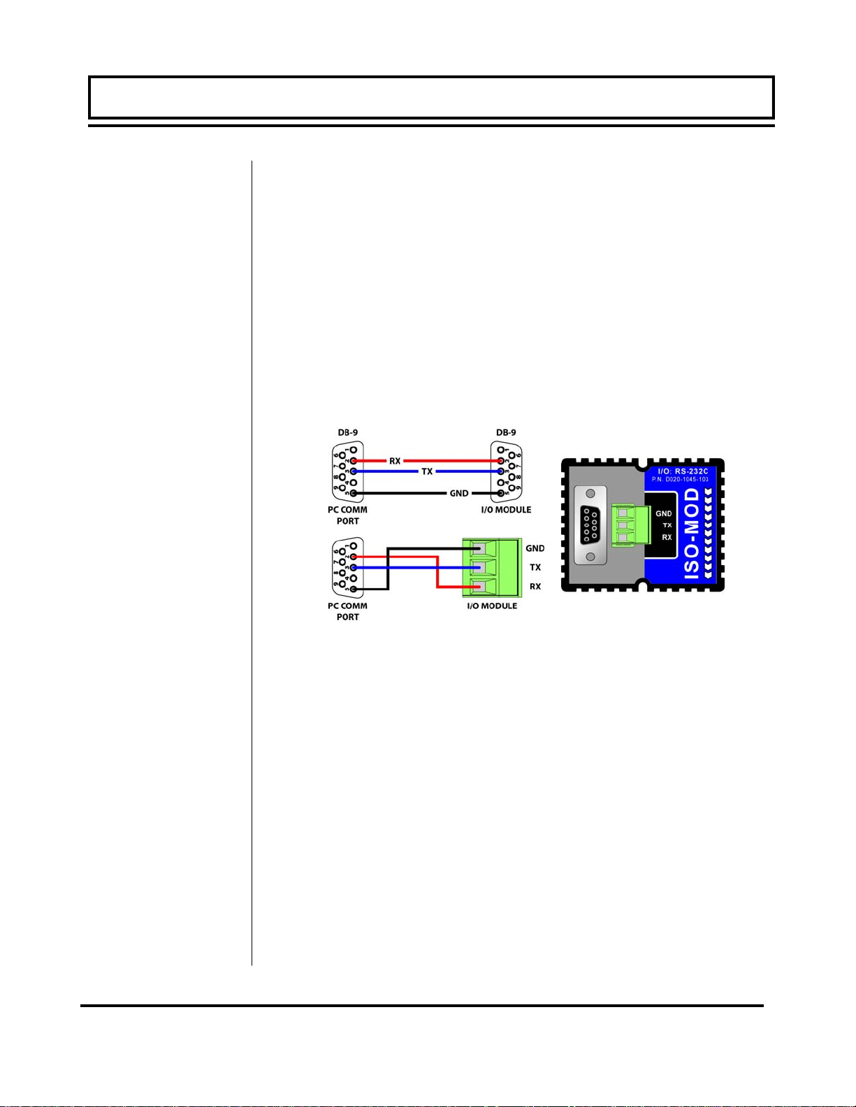
RS232C
The RS232C Module will interface with the serial communication
ports of PCs, PLCs and SCADA systems that are used to monitor
flow rate information in piping systems. A proprietary digital
communications protocol is used for this communication. An
explanation of the command structure is detailed in the Appendix
of this manual. Flow rate, total, signal strength and temperature (if
so equipped) can be monitored over the digital communications module. The RS232C Module may also be used to form a hardwire
connection to a PC that is running the UltraLink™ software utility.
Baud rates up to 19.2k are supported. Figure 1.14 illustrates
typical connections.
Figure 1.14
RS232 Connections
Rev. 2/2008 -1.20- MFX
Page 22
PART 1 - ISO-MOD
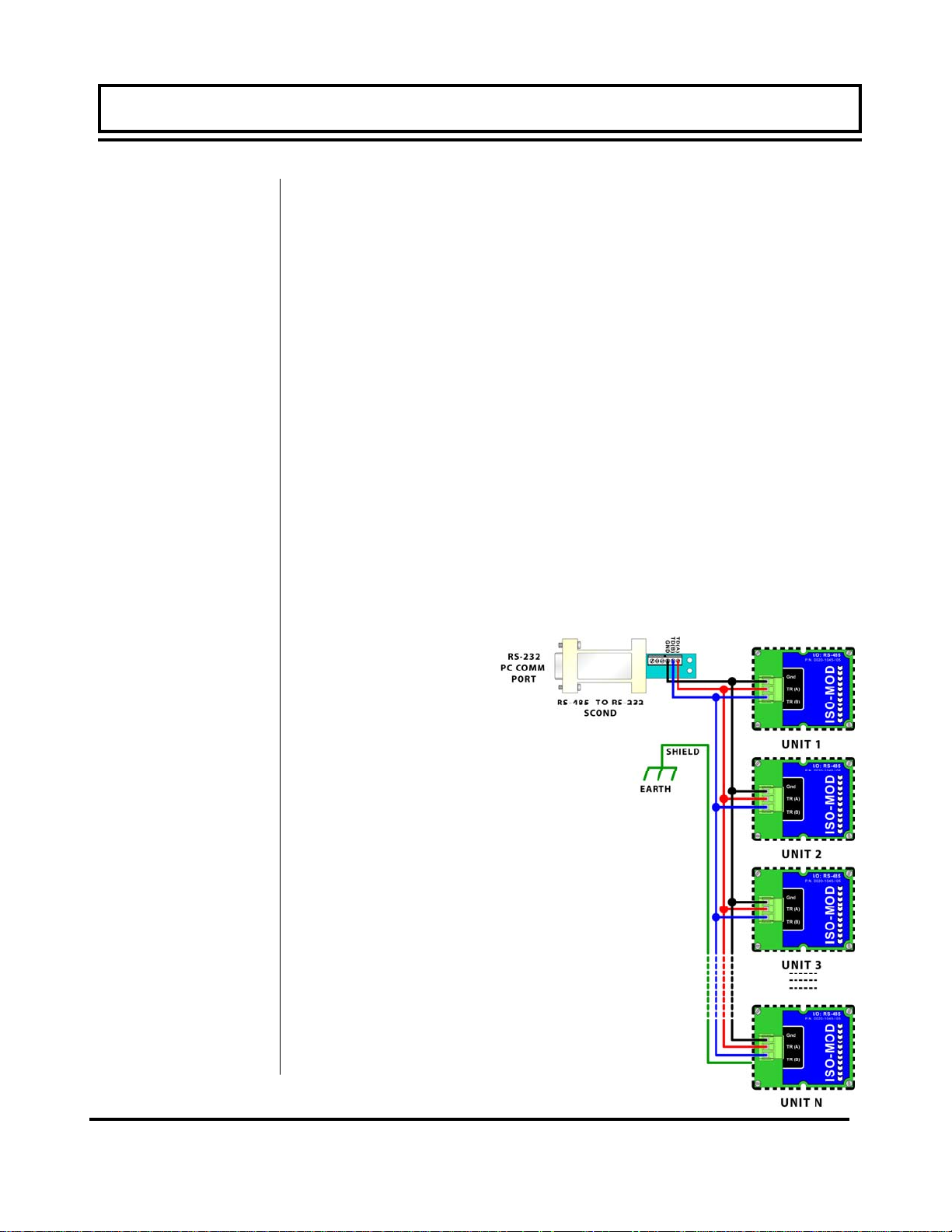
RS458
The RS485 Module allows up to 128 MFX systems to be placed on
a single three-wire cable bus. All meters are assigned a unique
one byte serial number that allows all meters on the cable network
to be independently accessed. A proprietary digital communications protocol is used for this communication. An explanation of
the command structure is detailed in the Appendix of this manual.
Flow rate, total, signal strength and temperature (if so equipped)
can be monitored over the digital communications bus. Baud rates
up to 9600 and cable lengths to 5,000 feet [1,500 meters] are
supported without repeaters or “end of line” resistors. UltraLink
™
is also compatible with a multiple MFX network, allowing individual
meters to be accessed, programmed, diagnosed and calibrated.
To interconnect meters, utilize three-wire shielded cable such as
Belden 9939 or equal. In noisy environments the shield should be
connected on one end to a good earth ground connection. An
RS232 to RS485 scond, such as B&B electronics p/n 485SD9TB
(illustrated in Figure 1.15) is required to interconnect the RS485
network to a communication port on a PC. If more than 128 meters
must be monitored, an additional scond and communication port is
required.
Figure 1.15
RS485 Network
Connections
Rev. 2/2008 -1.21- MFX
Page 23
PART 1 - ISO-MOD
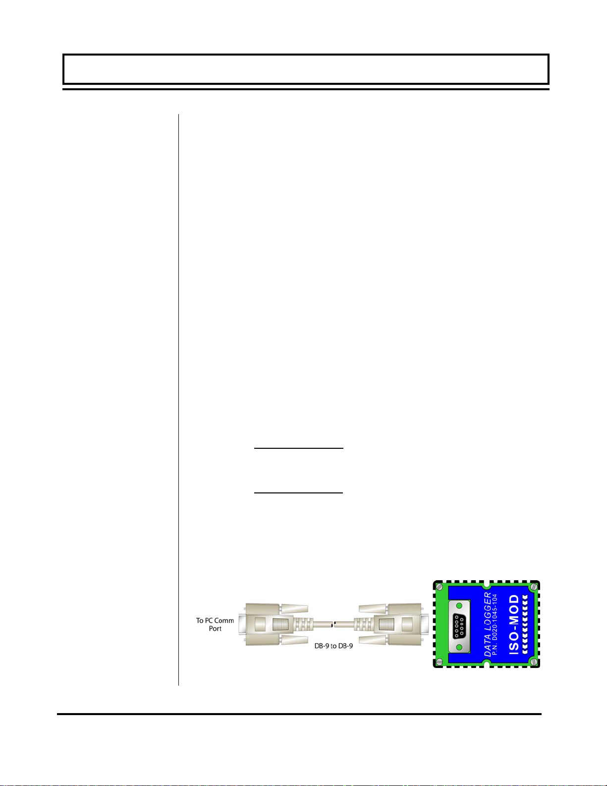
Data Logger
The 200,000 event data logger/electronic stripchart recorder can
be configured to match most user applications. The logger stores
time-stamped, high resolution (16-bit) data at user selected intervals ranging from 1 to 1,000 seconds. Configuration of and data
retrieval from the logger are detailed in Sections 3 and 4 of this
manual.
The module can be carried in a shirt pocket back to the office and
plugged into a PC serial port via the module’s integral DB-9 connector. See Figure 1.16. This eliminates the requirement to carry
a computer to the flow meter site. The data in the logger can also
be accessed without removing the module from the flow meter.
Open the door of the flow meter and interconnect the 9-pin cable
between the data logger and the PC serial communications port.
The logger is capable of storing up to 200,000 measurements. The
measurements are broken into 16 blocks or pages with a maximum number of data points per block of 30,000.
If each block(page) is filled to the maximum, 6-2/3 blocks would be
used:
If all 16 blocks are to be used, each block could hold 12,500 data
points:
NOTE: The data logger is not accessible using the MFX’s infrared
adapter. Communications between the data logger and computer
must be accomplished using a directly connected RS232C or
RS485 connection.
200,000 Points
30,000 Points
200,000 Points
16 Pages
= 6-2/3 Pages
= 12,500 Points per page
Rev. 2/2008 -1.22- MFX
Data Logger Connection
Figure 1.16
Page 24

PART 1 - ISO-MOD
Before Starting
the
Instrument
Instrument
Startup
Note: The MFX flow meter system requires a full pipe of liquid before a successful startup can be completed. Do not at-
tempt to make adjustments or change configurations until a full
pipe is verified.
Procedure:
1. Verify that all wiring is properly connected and routed as de-
scribed in Part 1 of this manual.
2. Verify that the MagProbe sensor is properly mounted as de-
scribed in Part 2 of this manual.
3. Apply power. The display of a MFXD2 will display a software
version number and then all of the segments will illuminate in
succession. The meter will then enter run mode.
4. Verify that the following parameters have been entered into the
MFX Flow Meter in the BASIC MENU (See Section 3 of this
manual):
• UNITS—either ENGLISH or METRIC
• K-FACTOR (as it appears on the MagProbe sensor)
• PIPE Outside Diameter
• PIPE Wall Thickness
• PIPE Liner Thickness
• RATE unit selected
• RATE interval selected
5. Once these parameters have been entered and saved, the flow
meter will begin to measure and display flow rate. Section 3 of
this manual describes in greater detail the configuration and
programming of the MFX instrument.
Rev. 2/2008 -1.23- MFX
Page 25
PART 2 - MAGPROBE INSTALLATION
MagProbe
Mounting
Considerations
Top View of Pipe
Figure 2.1
Step A -
Mounting
After unpacking, it is recommended to save the shipping carton
and packing materials in case the instrument is stored or reshipped. Inspect the equipment and carton for damage. If there is
evidence of shipping damage, notify the carrier immediately.
The DMP insertion probe that is utilized by the MFX flow meter
system contains an electromagnet, electrodes and amplification
circuitry. Three electrodes, two measurement and one ground, are
located in the black Ultem® plastic tip of the probe and are
designed to be inserted to the average fluid velocity point within a
pipe. Not all liquid within a pipe is flowing at a uniform fluid
velocity, but a long straight run of pipe, full of flowing liquid,
contains a predictable liquid velocity profile. By selecting proper
upstream and downstream lengths of straight pipe from the probe
installation point and by making precise insertion depths into the
pipe, very accurate and reliable volumetric flow rates and totals
can be obtained.
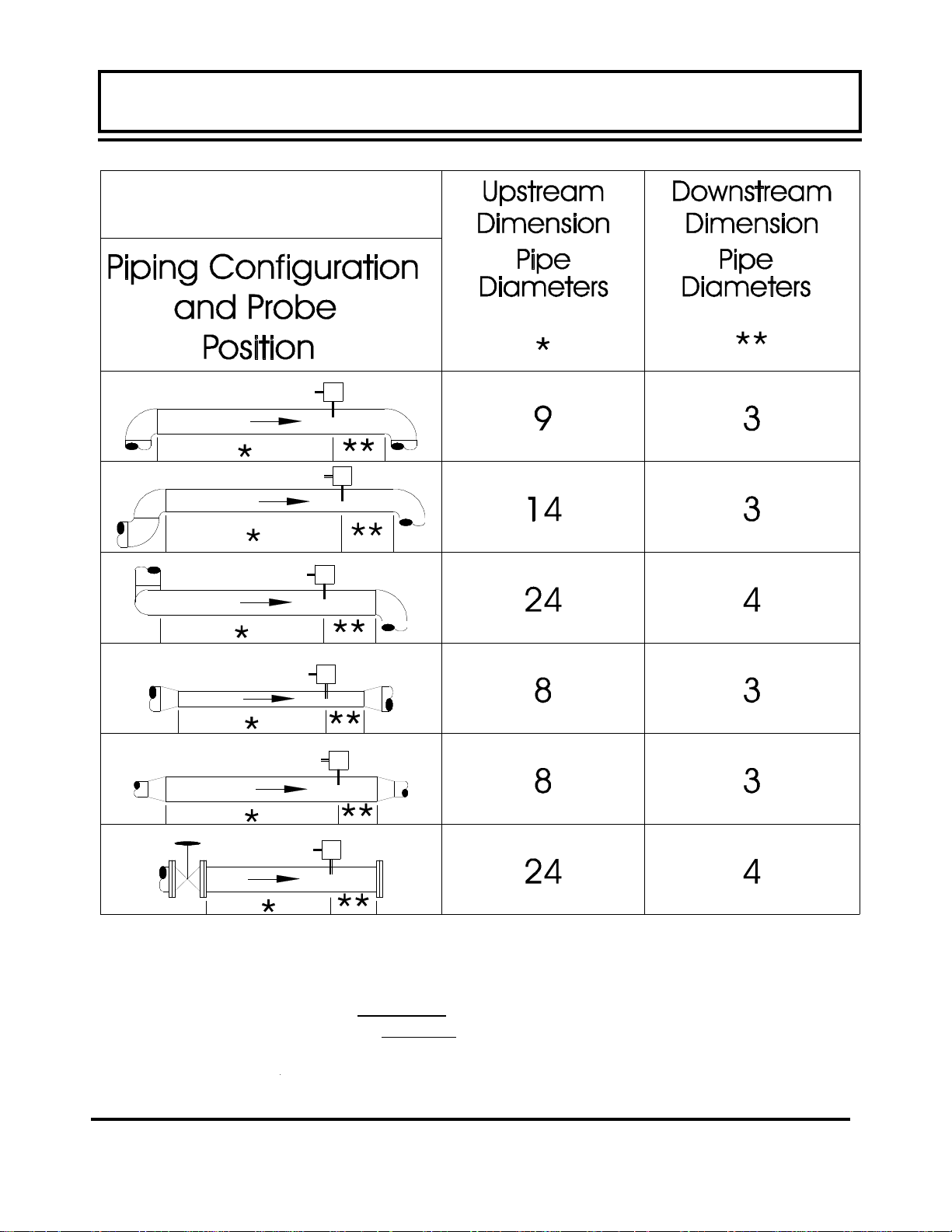
Select a probe mounting location with adequate straight runs
(without disturbances) of pipe, both upstream and downstream, to
achieve stable and accurate readings. Examples of minimum
upstream and downstream requirements are included in Table 2.1.
Note that if adequate straight plumbing cannot be provided, the
MFX system will operate repeatably
specified accuracy
When installing the DMP probe in a horizontal pipe, the preferred
orientation is between 1 and 5 o’clock on the pipe — assuming 12
o’clock as the top. See Figure 2.1. Ensure that the mounting
location allows for adequate clearance to install and retract the
probe fully from the pipe.
and will likely provide less stable readings.
, but will probably not achieve
Rev. 2/2008 -2.1- MFX
Page 26
PART 2 - MAGPROBE INSTALLATION
PART 2 - TRANSDUCER INSTALLATION
Table 2.1— Straight Pipe Recommendations
1
The MFX system will provide repeatable measurements on piping systems that do not
meet these requirements, but the accuracy of these readings may be influenced to various
degrees.
Rev. 2/2008 -2.2- MFX
1
Page 27

PART 2 - TRANSDUCER INSTALLATION PART 2 - MAGPROBE INSTALLATION
PART 2 - TRANSDUCER INSTALLATION
Step B - Hot
Tapped
Installation
The installation instructions cover Hot-Tapped installations
(installations where it is required to install or remove the Magprobe without shutting down the process pressure). If the
product is being installed without an isolation valve, ignore the
steps that pertain to its installation. Figure 2.2 illustrates an
exploded view of an isolation valve assembly and names the
various components.
Hot-tapped installation will require the installation of either a
welded pipe coupling or installation of a pipe saddle. The ball
valve and close nipple can be purchased as a kit from Dynasonics or can be procured at most hydraulic or plumbing supply
shops. The two critical factors that must be considered with the
components are pressure rating and internal sizes. The DMP2
through DMP6 1-1/2” MagProbes are designed to operate with
pipe pressures up to 700 psi [48 Bar]. Verify that the internal port
of the opened valve is at least 1-1/2 inches [38 mm] to permit
free passage of the probe without interference. Attempts to force
a MagProbe through an opening smaller that stated will damage
the probe tip and void the warranty.
Rev. 2/2008 -2.3- MFX
Figure 2.2
Page 28

PART 2 - TRANSDUCER INSTALLATION PART 2 - MAGPROBE INSTALLATION
PART 2 - TRANSDUCER INSTALLATION
Step C -
Component
Assembly
These instructions call for the use of a drilling machine designed
for drilling holes in pipes that are under pressure (for example,
Muller Co., Decatur, Illinois manufactures products for this purpose).
Procedures are as follows:
1. Verify that the line pressure within the pipe is within the rated
limits of the pressure drilling machine, welded coupling or pipe
saddle, valve and MagProbe to be used.
2. Grind off paint or other coatings from the pipe in the area
where the DMP MagProbe Assembly is to be installed.
Recommended minimum straight pipe lengths for best
accuracy are 10 diameters upstream and 5 downstream. See
Table 2.1.
3. Tack weld a 1½" NPT female weld-coupling to the pipe or
install a pipe saddle according to the suppliers instructions.
The coupling or saddle must be aligned perpendicular to
the pipe axis and square to its plane.
4. Complete welding. A water tight, 0.25" minimum weld bead is
recommended.
5. Install the close nipple into the weld coupling. Use appropriate
pipe sealants.
6. Install the isolating ball valve on the close nipple. Verify that
the valve is in fully open position.
7. Install drill bit and adapter into the pressure drilling machine.
Then attach the machine to the isolation valve.
8. Drill through the pipe wall in accordance with the instructions
supplied with the drilling machine.
9. Withdraw the drill bit through the isolating valve. Close the
valve and remove the drilling machine. Check for leakage at
valve and connections.
Rev. 2/2008 -2.4- MFX
Page 29

PART 2 - TRANSDUCER INSTALLATION PART 2 - MAGPROBE INSTALLATION
PART 2 - TRANSDUCER INSTALLATION
PART 2 -
Step D -
Probe
Insertion
Distances
PROBE INSERTION
Before inserting the MagProbe into the piping system, it is
necessary to calculate the probe insertion depth that will place the
measuring electrodes at the proper position in the pipe. In order to
complete this calculation, some knowledge of the piping system
must be known. Refer to the paragraphs that follow and Figure
2.3 for information regarding this process. The variables required
are
• The overall probe length
• Pipe internal diameter
• Pipe wall thickness (including liners)
• The length of the valve stack
• Amount of straight pipe diameters in the system
Using this information and referring to Figure 2.3 proper insertion
depth can be determined.
Measurement A — the typical depth that the MagProbe tip is inserted into the piping system is 1/8 (12.5%) of the pipe internal diameter. Assume 1/8 of the pipe internal diameter unless a system
piping configuration does not have at least 15 pipe diameters of
straight pipe in the installation area.
Measurement B — Pipe wall thickness. This information can be
obtained from standard pipe wall charts (See the Appendix of this
manual) or ideally can be measured using an ultrasonic wall thickness gauge. If the pipe is lined, include the liner thickness in this
measurement.
Measurement C — Measure the distance that is going to be taken
up by the pipe tap, nipple, full-flow ball valve and the insertion fitting.
Note: DMP1 through DMP6 probes utilize 1-1/2” NPT hardware.
The insertion fitting for the DMP1 through DMP6 probes is approximately 2.5 inches long once completely torqued into position.
Measurement E — This is the overall length of the probe measured from the black measurement tip to the top flange on the
probe.
Measurement D — This is the length of MagProbe that will be
protruding from the insertion fitting after it is inserted to the proper
depth in the fluid stream.
Rev. 2/2008 -2.5- MFX
Page 30

PART 2 - TRANSDUCER INSTALLATION PART 2 - MAGPROBE INSTALLATION
PART 2 - TRANSDUCER INSTALLATION
PART 2 -
TO CALCULATE INSERTION DEPTH
Measure and record the following linear
distances:
E = PROBE LENGTH = _______
C = INSERTION FITTING to PIPE WALL
= _______
B = PIPE WALL THICKNESS
= _______
A = 0.125 x PIPE ID = _______
D = INSERTION DEPTH = _______
D = E - C - B - A
Installation Measurements: DMP2 through
DMP6 MagProbes
Figure 2.3
Rev. 2/2008 -2.6- MFX
Page 31

PART 2 - TRANSDUCER INSTALLATION PART 2 - MAGPROBE INSTALLATION
PART 2 - TRANSDUCER INSTALLATION
Step E -
Cable Routing
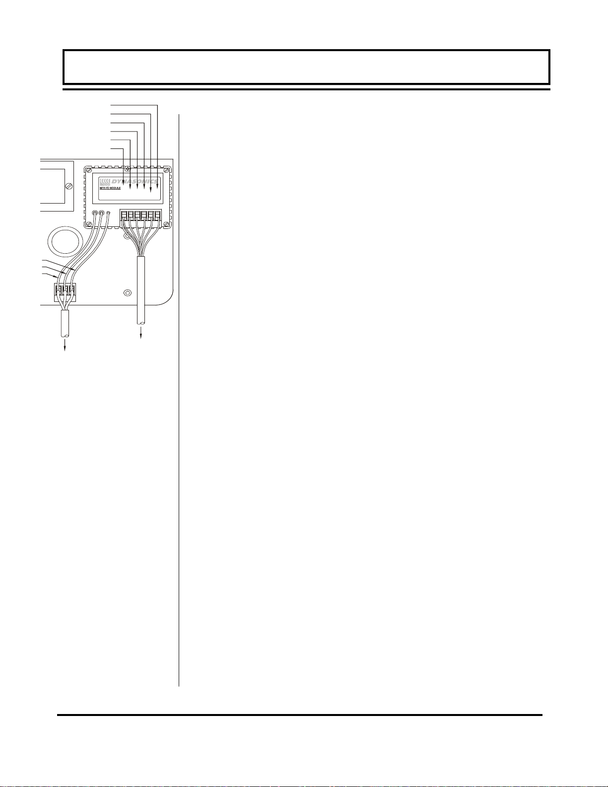
PROBE CABLE
Before inserting the MagProbe into the pipe, the sensor cables
should be routed to the transmitter location. Locate the transmitter
within the length of MagProbe cable that was supplied with the
MFX system. If this is not possible, replace the entire length of interconnect cable with Belden part number 9536, Dynasonics part
number D005-1003-003 or equivalent. Do not splice the cable as
shield integrity will be compromised and poor performance can result. Cable lengths up to 1000 feet [300 meters] can be utilized.
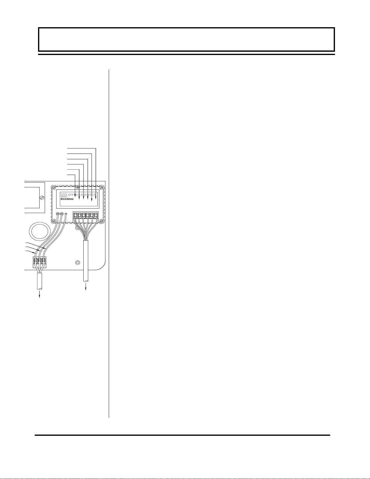
The wiring inside of the MagProbe conduit box is pictured in Fig-
ures 2.5.
Figure 2.5
MagProbe Interface
Enclosure
IMPORTANT
NOTE!
Rev. 2/2008 -2.7- MFX
CAUTION: Both power and digital signals are carried through the
MagProbe cable. These signals are robust, but care should be
taken in routing the cables. Avoid running cables near sources of
high voltage equipment or sources of extreme electrical noise—
high EMI/RFI. Also avoid routing the cables in cable tray
configurations, unless the trays are specifically used for other low
voltage, low level, signal cables.
PROBE GROUND CONNECTION
Attach a wire of 12 AWG or larger between the #10-32 ground lug
on the insertion fitting and earth ground.
Page 32

PART 2 - TRANSDUCER INSTALLATION PART 2 - MAGPROBE INSTALLATION
PART 2 - TRANSDUCER INSTALLATION
Step F -
MagProbe
Insertion DMP2
through DMP6
MAGPROBE INSERTION DMP2 through DMP6
1. Apply sealant to the 1-1/2” NPT threads of the insertion fitting
assembly. Screw the assembly into the isolation valve and
tighten with a 2-1/2” pump wrench. Final orientation of the two
threaded rods on the MagProbe insertion fitting should be approximately perpendicular to the pipe’s axis.
2. Run the lower Jam nuts down to a point that approximates the
final insertion position or at least far enough to allow insertion
of the MagProbe into the insertion Fitting. Using the threaded
rods as a guide and with the flow direction arrow pointing in the
correct direction, position the MagProbe in the insertion fitting.
Continue to insert the MagProbe as far into the isolation
assembly as possible. The MagProbe tip will come in contact
with the closed "ball" in the isolation valve.
CAUTION: Do Not Force the MagProbe Tip Against the "Ball", as
damage to the MagProbe tip may result.
3. Replace the upper Jam Nuts (2 on each rod) and the cotter
pins. The nuts should be run down to the top side of the
retaining collar and the cotter pins replaced. Orient the MagProbe in the direction of flow as indicated on by the FLOW
direction arrow located on the top of the MagProbe amplifier
enclosure. See Figure 2.6.
Figure 2.6
CAUTION: The nuts on both ends of the retaining rods must
always be in place as a safety measure to prevent possible MagProbe blow out. Inserting cotter pins is a further safety measure.
4. Slowly open the isolation valve. When the valve is fully open,
use a 9/16” wrench on the insertion nuts, alternately tightening
Rev. 2/2008 -2.8- MFX
Page 33

PART 2 - TRANSDUCER INSTALLATION PART 2 - MAGPROBE INSTALLATION
PART 2 - TRANSDUCER INSTALLATION
Retracting
DMP2 through
DMP6 Probes
each nut about two complete turns to avoid uneven seal
loading—two 9/16” ratcheting wrenches can expedite this process. Repeat until the length of probe remaining above the seal
fitting equals the “D” length calculated in step D.
NOTE: For some low pressure\low temperature (less than 30 psi
[2 Bar] and less than 100
in by hand to decrease the insertion time. Dynasonics also offers
insertion cranking tools for these probes.
PROBE RETRACTION PROCEDURE
1. Retract the MagProbe by loosening the Upper Jam nuts
counterclockwise — as viewed from the top of the MagProbe
using a 9/16” wrench. If the pipe is under pressure, the nuts
must be turned alternately about two turns at a time to prevent
binding as a result of non-equal seal loading — two 9/16” ratcheting wrenches can expedite this process. In many cases, the
line pressure will cause the MagProbe to retract. Should the
MagProbe bind or if system pressure is very low, use the
retraction nuts on the lower side of the MagProbe flange to
assist in the MagProbe retraction. Continue this procedure
until the MagProbe is fully retracted into the insertion fitting.
CAUTION: Do not run the drive nuts off the rods until the isolation
valve is fully closed.
2. After the MagProbe is retracted past the "ball” in the isolation
valve, the Isolation Valve may be closed to isolate the MagProbe from the line and the MagProbe can be removed
entirely.
CAUTION: If the probe tip is not above the "ball" of the isolation
valve, the valve cannot be closed. If the valve will not close
smoothly, the body or tip of the MagProbe is most likely not above
the "ball".
may result in damage to the probe.
Attempting to force the valve into the closed position
o
F [38oC] the MagProbe may be pushed
Rev. 2/2008 -2.9- MFX
Page 34

PART 3 - KEYPAD CONFIGURATION
General
Keypad
Operation
After installation of the MagProbe sensor and connection of
appropriate power supplies to the MFX, keypad configuration of
the instrument can be undertaken. All entries are saved in nonvolatile FLASH memory and will be retained in the event of power
loss.
The DMFXD2 is configured through the keypad interface and the
DMFXD1 is configured through a software utility at the
Dynasonics factory.
The MFX contains a four-key tactile feedback keypad interface
that allows the user to view and change configuration parameters
used by the MFX operating system.
1. The MENU key is pressed from RUN mode to enter
PROGRAM mode. The MENU key is pressed in PROGRAM
mode to exit configuration parameters and menus. If changes
to any configuration parameters have been made, the user will
be prompted with a SAVE?YES when returning to RUN mode.
2. The ARROW keys are used to scroll through menus and
configuration parameters. The ARROW keys are also used to
adjust parameter numerical values.
3. The ENTER key is pressed from the RUN mode to view the
Rev. 2/2008 -3.1- MFX
Page 35

Menu
Structure
PART 3 - KEYPAD CONFIGURATION
current software version operating in the instrument.
• used to access the configuration parameters in the various
menus.
• Used to initiate changes in configuration parameters.
• Used to accept configuration parameter changes.
The MFX software is structured using menus. A Map of the user
interface has been included in the Appendix of this manual. The
Map provides a visual path to the configuration parameters that
users need to access. This tool should be employed each time
configuration parameters are accessed or revised.
The five menus used in the structure of the MFX are as follows:
1. BSC MENU -- BASIC operations menu. It contains all of the
configuration parameters necessary to program the meter to
measure flow.
2. OUT1 MEN -- Configures the type and operating parameters of
the ISO-MOD located in Module #1 position.
3. SEC MENU -- SECURITY MENU utilized for resetting
totalizers, resetting the operating system and revising security
passwords.
4. SER MENU -- SERVICE MENU contains system
measurements that are used by service personnel for
troubleshooting instruments installed on piping systems.
5. DSP MENU -- DISPLAY MENU used to configure meter display
functions.
Rev. 2/2008 -3.2- MFX
Page 36

PART 3 - KEYPAD CONFIGURATION
The following sections define the configuration parameters located
in each of the menus.
1. BASIC MENU
The BASIC menu contains all of the configuration parameters
necessary to make the MFX operational.
UNITS
Selection
IMPORTANT!
K-factor Entry
UNITS
ENGLSH
METRIC
Installs a global measurement standard into the operation of the
instrument. The choices are either English or Metric
measurements.
• Select ENGLSH if all configurations (pipe sizes, etc.) are to be
made in inches. Select METRIC if the meter is to be
configured in millimeters.
NOTE: If the UNITS entry has been changed from ENGLSH to
METRIC or from METRIC to ENGLSH, the entry must be saved
and the instrument reset (power cycled or System Reset entered)
in order for the MFX to initiate the change in operating units. Failure to save and reset the instrument may result in meter not measuring properly.
K FACTOR -- MagProbe K-Factor Entry
0.1—100.00
Each MagProbe has a unique K-Factor that is factory set and
recorded on the information tag located on the MagProbe flow
sensor. To enter the MagProbe K-Factor into the MFX, press the
ENTER key, then use the up/down arrow keys to adjust displayed
value to equal the unique K-Factor value. When the value is
proper, press the ENTER key to record the value. This procedure
must be followed if a replacement MagProbe is procured from the
Dynasonics factory.
Rev. 2/2008 -3.3- MFX
Page 37

PART 3 - KEYPAD CONFIGURATION
Pipe Diameter
Pipe Wall
Thickness
PIPE OD -- Pipe Outside Diameter Entry
ENGLSH (Inches)
METRIC (Millimeters)
Enter the pipe outside diameter in inches if ENGLSH was
selected as UNITS; in millimeters if METRIC was selected.
IMPORTANT NOTE: Charts listing popular pipe sizes have been
included in the Appendix of this manual. Correct entries for pipe
O.D. and pipe wall thickness are critical to obtaining accurate flow
measurement readings.
PIPE WT -- Pipe Wall Thickness Entry
ENGLSH (Inches)
METRIC (Millimeters)
Enter the pipe wall thickness in inches if ENGLSH was selected as
UNITS; in millimeters if METRIC was selected.
IMPORTANT NOTE: Charts listing popular pipe sizes have been
included in the Appendix of this manual. Correct entries for pipe
O.D. and pipe wall thickness are critical to obtaining accurate flow
measurement readings.
LINER T -- Pipe Liner Thickness Entry
Liner
Thickness
ENGLSH (Inches)
METRIC (Millimeters)
Enter the pipe liner thickness
ENGLSH was selected as UNITS; in millimeters if METRIC was
selected.
IINS DEPTH -- Insertion Depth Entry
. Enter this value in inches if
Insertion
ENGLSH (Inches)
Depth
Rev. 2/2008 -3.4- MFX
METRIC (Millimeters)
Data defaulted to .125 x pipe I.D. No manual entry is necessary.
Page 38

PART 3 - KEYPAD CONFIGURATION
Engineering
Units—RATE
Engineering
Units—RATE
INTERVAL
Engineering
Units—TOTAL
RATE UNT - Engineering Units for Flow Rate
GALLONS - U.S. Gallons
LITERS - Metric Liter
MGAL - Millions of U.S. Gallons
CUBIC FT - Cubic Feet
CUBIC ME - Cubic Meters
ACRE FT - Acre Feet
OIL BARR - Oil Barrels (42 U.S. Gallons)
LIQ BARR - Liquor Barrels (31.5 U.S. Gallons)
FEET - Linear Feet
METERS - Linear Meters
Select a desired engineering unit for flow rate measurements.
RATE INT - Time Interval for Flow Rate
MIN - Minutes
HOUR - Hours
DAY - Days
SEC - Seconds
Select a desired engineering unit for flow rate measurements.
TOTL UNT - Engineering Units for Flow Totalizer
GALLONS - U.S. Gallons
LITERS - Metric Liter
MGAL - Millions of U.S. Gallons
CUBIC FT - Cubic Feet
CUBIC ME - Cubic Meters
ACRE FT - Acre Feet
OIL BARR - Oil Barrels (42 U.S. Gallons)
LIQ BARR - Liquor Barrels (31.5 U.S. Gallons)
FEET - Linear Feet
METERS - Linear Meters
Select a desired engineering unit for flow accumulator (totalizer)
measurements.
Rev. 2/2008 -3.5- MFX
Page 39

PART 3 - KEYPAD CONFIGURATION
Engineering
Units—TOTAL
Exponent
TOTL E - Flow Totalizer Exponent Value
E-1 to E6
Utilized for setting the flow totalizer exponent. This feature is
useful for accommodating a very large accumulated flow. The
exponent is a "X10
+6 (X 1,000,000).Table 3.5 should be referenced for valid entries
and their influence on the DMFX display.
Exponent Display Multiplier
E-1
E0
E1
E2
E3
E4
n
" multiplier, where "n" can be from -1 (X 0.1) to
x 0.1 (÷10)
x 1 (no multiplier)
x 10
x 100
x 1,000
x 10,000
Minimum Flow
Rate
Maximum
Flow Rate
E5
E6
MIN RATE -- Minimum Flow Rate Settings (Value)
Rate Unit/Rate Interval
A minimum volumetric flow rate setting is entered to establish filter
software settings. Volumetric entries will be in the Engineering
Rate Units and Interval selected on pages 3.9 and 3.10 of this
manual. For unidirectional measurements, set MIN RATE to zero.
For bi-directional measurements, set MIN RATE to the highest
negative (reverse) flow rate expected in the piping system.
MAX RATE -- Maximum Flow Rate Settings (Value)
Rate Unit/Rate Interval
A maximum volumetric flow rate setting is entered to establish filter
software settings. Volumetric entries will be in the Engineering
x 100,000
x 1,000,000
Rev. 2/2008 -3.6- MFX
Page 40

PART 3 - KEYPAD CONFIGURATION
Low Flow
Cut-off
System
Damping
Rate Units and Interval selected on pages 3.9 and 3.10 of this
manual. Set MAX RATE to the highest (positive) flow rate
expected in the piping system.
FL C-OFF - Low Flow Cut-off
Percent of MAX RATE
A Low Flow Cut-off entry is provided to allow very low flow rates
(that can be present when pumps are off and valves are closed) to
be displayed as Zero flow. Typical values that should be entered
are between 1.0% and 5.0% of full-scale.
DAMP PER - System Damping
Relative Percent Entry
DAMP PER establishes a maximum adaptive filter value. Under
stable flow conditions (flow that varies less than ±5%) this adaptive
filter will increase the number of successive flow readings that are
averaged together up to this maximum value. If flow changes
outside of the ±5% window, the Flow Filter adapts by decreasing
and allows the meter to react faster. A minimum filter setting is
established with the MIN DAMP setting described below. DAMP
PER is usually set to a value that is equal to or greater than MIN
DAMP. Increasing this value tends to provide smoother steady-
state flow readings and outputs.
Minimum
System
Damping
Rev. 2/2008 -3.7- MFX
MIN DAMP - System Damping
Relative Percent Entry
In installations where very turbulent or erratic flow is encountered,
increasing the MIN DAMP setting can increase display and output
stability by forcing more averaging of flow readings. This filter is
not adaptive, so increasing this setting will decrease the response
time of the instrument to all changes in flow rate. MIN DAMP is
usually set to a value that is equal to or less than DAMP PER.
Page 41

PART 3 - KEYPAD CONFIGURATION
2. OUTPUT #1 MENU
4-20mA
4-20mA Span
ISO-MOD 4-20mA
FL 4MA
FL 20MA
CAL 4MA
CAL 20MA
4-20 TST
Configured via jumper selections into either a passive or active
transmission mode (See Section 2 for details), the 4-20 mA Output
Module interfaces with virtually all recording and logging systems
by transmitting an analog current signal that is proportional to
system flow rate. Independent 4 mA and 20 mA span settings are
established in software using the Flow Measuring Range entries.
These entries can be set anywhere in the –30 to +30 FPS [-9 to +9
MPS] measuring range of the instrument. Output resolution of the
module is 12-bits (4096 discrete points) and the module can drive
up to 800 ohms of load with its internal 24V isolated power source.
The FL 4MA and FL 20MA entries are used to set the span of the
4-20 mA analog output. These entries are volumetric rate units
that are equal to the volumetric units configured as Engineering
Rate Units and Engineering Units Time Interval entered on page
3.10. These entries may be entered anywhere in the flow
measurement range of the instrument (velocity range of –30 to
+30 FPS [-9 to +9 MPS]).
NOTE: The Minimum Rate may be set anywhere in the flow
measurement range of –30 to +30 FPS [-9 to +9 MPS]). For
example: If bi-directional flow needs to be logged, set the MIN
RATE at a negative value.
For example, to span the 4-20mA output from –100 GPM to +100
GPM, with 12mA being 0 GPM, set the FL 4MA and FL 20MA
inputs as follows:
Rev. 2/2008 -3.8- MFX
Page 42

PART 3 - KEYPAD CONFIGURATION
4-20mA
Calibration
FL 4MA = -100.0
FL 20MA = 100.0
For example, to span the 4-20mA output from 0 GPM to +100
GPM, with 12mA being 50 GPM, set the FL 4MA and FL 20MA
inputs as follows:
FL 4MA = 0.0
FL 20MA = 100.0
The 4-20mA ISO-MOD is factory calibrated and should not require
adjustment unless it is replaced.
The CAL4MA entry allows fine adjustments to be made to the
“zero” of the 4-20mA output. To adjust the 4mA output, an
ammeter or reliable reference connection to the 4-20mA output
must be present.
NOTE: The CAL 4MA and CAL 20MA entries should not be used
in a attempt to set the 4-20mA range. Utilize FL 4MA and FL
20MA, detailed above, for this purpose.
Procedure:
1. Disconnect one side of the current loop and connect the
ammeter in series (disconnect either wire at the terminals
labeled +/- on the ISO-MOD 4-20mA module).
2. Using the arrow keys, increase the numerical value to increase
the current in the loop to 4mA. Decrease the value to decrease
the current in the loop to 4mA. Typical values range between
40-80 counts.
Re connect the 4-20mA output circuitry as required.
Calibration of the 20mA setting is conducted much the same way
as the 4mA adjustments.
Procedure:
1. Disconnect one side of the current loop and connect the
ammeter in series (disconnect either wire at the terminals
Rev. 2/2008 -3.9- MFX
Page 43

PART 3 - KEYPAD CONFIGURATION
labeled +/- on the ISO-MOD 4-20mA module).
2. Using the arrow keys, increase the numerical value to increase
the current in the loop to 20mA. Decrease the value to
decrease the current in the loop to 20mA. Typical values range
between 3700-3900 counts.
Re connect the 4-20mA output circuitry as required.
4-20mA Test
Rate Pulse/
Freq
4-20 TST - 4-20mA Output Test
4-20
Allows a simulated value to be output on from the 4-20mA output.
By incrementing this value, the 4-20mA output will transmit the
indicated current value. This feature can be utilized to confirm
connectivity with chart recorders, data acquisition systems or other
monitoring equipment.
ISO-MOD: RATE PULSE (Value)
Flow at 0 Hz (FL 0H)
Flow at 2.5k Hz (FL 2.5KH)
NOTE: The Maximum Rate may be set anywhere in the flow
measurement range of –30 to +30 FPS [-9 to +9 MPS]. For
example: If bi-directional flow needs to be logged, set the MIN
RATE at a negative
The Rate Pulse Output Module is utilized to transmit information to
external counters and PID systems via a frequency output that is
proportional to system flow rate. Independent Zero and Span
settings are established in software using the Flow Measuring
Range entries. Output resolution of the module is 12-bits (4096
discrete points) and the maximum output frequency setting is
2,500
simulation and “open collector”. The turbine meter simulation
sources a non-ground referenced saw-tooth waveform with a
maximum amplitude of approximately 500 mV p-p. The open
collector output utilizes a 0.21 Ohm FET output that is rated to
Hz. The module has two output modes, turbine meter
value and MAX RATE at a positive value.
Rev. 2/2008 -3.10- MFX
Page 44

PART 3 - KEYPAD CONFIGURATION
operate at 100 V and 1 A maximum. If the open collector output is
utilized, an external voltage source and limit resistor must be
present. See Part 1 of this manual for connection information.
Rate Pulse
Span
The FL 0H and FL 25KH entries are used to set the span of
the 0 to
rate units that are equal to the volumetric units configured as
Engineering Rate Units and Engineering Units Time Interval
entered on pages 3.11 and 3.12 of this manual.
For example, in a bi-directional system, to span the 0 to 2.5k Hz
output from –100 GPM to +100 GPM, with 1.25k Hz being 0 GPM,
set the FL 100H and FL 10KH inputs as follows:
FL 0H = –100.0
FL 25KH = 100.0
For example, to span the 0 to 2.5k Hz output from 0 GPM to +100
GPM, with 1.25k Hz being 50 GPM, set the FL 0H and FL 25KH
inputs as follows:
FL 0H = 0.0
FL 25KH = 100.0
2.5k Hz frequency output. These entries are volumetric
Dual Relay
Rev. 2/2008 -3.11- MFX
ISO-MOD Dual Relay
RELA Y 1 AND RELAY 2
NONE
TOTALIZE
TOT MULT
FLOW
ON
OFF
SIG STR
ERRORS
Two independent SPDT (single-pole, double-throw, Form C) relays
are contained in this module. The relay operations are user
configured via software to act in either a flow rate alarm, signal
Page 45

PART 3 - KEYPAD CONFIGURATION
Batch/
Totalizer Relay
Flow Rate
Relay
Error Alarm
Relay
strength alarm, error alarm or totalizer/batching mode. The relays
are rated for 200 VAC max. and a have current rating of 0.5A
resistive load [175 VDC @ 0.25A resistive]. It is highly
recommended that a slave relay be utilized whenever the Control
Relay ISO-MOD is used to control inductive loads such as
solenoids and motors.
TOTALIZE mode configures the relay to output a 50 mSec pulse
(contact changeover) each time the display totalizer increments —
divided by the TOT MULT. The TOT MULT value must be a
whole, positive, numerical value.
For example, if the Totalizer Exponent is set to E0 (x1) and the
Relay Multiplier is set to 1, then the relay will pulse each time the
totalizer increments one count, or each single, whole
measurement unit totalized.
If the Totalizer Exponent is set to E2 (x100) and the Relay
Multiplier is set to 1, then the relay will pulse each time the display
totalizer increments or once per 100 measurement units totalized.
If the Totalizer Exponent is set to E0 (x1) and the Relay Multiplier
is set to 2, the relay will pulse once for every two counts that the
totalizer increments.
Flow Rate Relay configuration permits relay changeover at two
separate flow rates allowing operation with an adjustable switch
deadband. Figure 3.1 illustrates how the setting of the two set
points influences rate alarm operation.
A single-point flow rate alarm would place the ON> setting slightly
higher than the OFF< setting – allowing a switch deadband to be
established. If a deadband is not established, switch chatter (rapid
switching) may result if the flow rate is very close to the switch point.
When a relay is set to ERROR mode, the relay will activate when
any error occurs in the flow meter that has caused the meter to
stop measuring reliably. See the Appendix of this manual for a list
of potential error codes.
Rev. 2/2008 -3.12- MFX
Page 46

PART 3 - KEYPAD CONFIGURATION
Figure 3.1
Single Point Alarm Operation
RS232C
Module
RS-485 I/O
ISO-MOD RS-232C
Baud Rate (RS232 BA)
1200 Baud (1200)
2400 Baud (2400)
9600 Baud (9600)
19,200 Baud (19200)
The RS232C Module can be interfaced with serial communication
ports of PCs, PLCs and SCADA systems. This module runs a
proprietary digital protocol, detailed in the Appendix of this manual,
that is used to monitor flow rate information in piping systems.
The RS232C Module may also be used to form a hardwire
connection to a PC that is running the UltraLink
Baud rates up to 19.2k are supported.
ISO-MOD RS485 (Choices and Values)
RS485 Mode (RS485 MO)
Slave (SLAVE)
Master (MASTER)
Baud Rate (RS485 BA)
1200 Baud (1200)
2400 Baud (2400)
9600 Baud (9600)
™
software utility.
Rev. 2/2008 -3.13- MFX
Page 47

PART 3 - KEYPAD CONFIGURATION
19,200 Baud (19200)
Device Address (1-127)
The RS485 Module allows up to 126 MFX systems to be daisychained on a single three-wire cable network. Communications
are through a proprietary digital protocol, detailed in the Appendix
of this manual. All meters are assigned a unique one byte serial
number that allows all of the meters on the cable network to be
accessed independently. Baud rates up to 19.2k and cable
lengths to 5,000 feet [1,500 meters] are supported without the
need for repeaters.
RS485 MO
Select SLAVE for all of the MFX meters connected to the unit
designated as MASTER.
RS485 BA
Data Logger
Option
Select a Baud rate that is compatible with the operating system.
ADDRESS
Each MFX connected on the communications bus must have an
unique address number assigned. Address 127 is a universal
address that will result in all MFX instruments on the network
responding simultaneously — regardless of address — resulting in
CRC errors. Only select address location 127 if one meter is on
the network.
ISO-MOD: DATALOGGER (Value)
LOGGING INTERVAL
From the OUTPUT 1 menu, select the time INTERVAL between
readings. INTERVAL values between 1 and 30,000 seconds are
acceptable.
For reference there are:
60 seconds in 1 minute
300 seconds in 5 minutes
1,800 seconds in 30 minutes
3,600 seconds in 1 hour
30,000 seconds in 8.33 hours
Rev. 2/2008 -3.14- MFX
Page 48

PART 3 - KEYPAD CONFIGURATION
Table 3.6 describes some typical configurations of the INTERVAL
and DURATION times with what the expected data samples
collected count will be.
Example No. INTERVAL
Table 3.6 — Interval and Duration Times
DURATION
Seconds
1 1 24 (1 day) 86,400
2 10 168 (7 days) 60,480
Hours
Operated
Samples
Collected
3 60 (1min) 720 (30 days) 43,200
4 300 (5 min) 8,760 (1 yr) 105,120
5 1,800 (30 min) 8,760 (1 yr) 17,520
6 3,600 (1 hr) 8,760 (1 yr) 8,760
7 18,000 (5 hr) 26,280 (3 yr) 17,520
3. SECURITY MENU
The SEC MENU allows the user to make password revisions,
reset the flow totalizer and reset the transmitter microprocessor.
TOT RES
Totalizer
RESET
NO
YES
Select YES to reset the Positive, Negative and Net flow totalizer/
accumulator to Zero.
Rev. 2/2008 -3.15- MFX
Page 49

PART 3 - KEYPAD CONFIGURATION
System
RESET
Change
Password
Signal
Strength
SYS RSET
NO
YES
Select YES to initiate a microprocessor reset. All system
configurations and totalizer values will be maintained.
CH PSWD? -- Change the Security Password
0-9999
By changing the Security Password from 0 to some other value
(any value between 1-9999), configuration parameters will not be
accessible without first entering that value when prompted. If the
value is left at 0, no security is invoked and unauthorized changes
could be made.
4. SERVICE MENU
SIG STR - Signal Strength
This feature is not activated on the MFX flow meter product.
Signal
Strength
Cutoff
Substitute
Flow Entry
Rev. 2/2008 -3.16- MFX
SIG C-OF - Signal Strength Cutoff
This feature is not activated on the MFX flow meter product.
SUB FLOW - Substitute Flow
Substitute Flow or SUB FLOW is a value that the analog outputs
and the flow rate display will be driven at when an error condition
in the flowmeter occurs. The typical setting for this entry is a value
that will make the instrument display zero flow during an error
condition. TABLE 3.2 below lists some typical settings to achieve
“Zero” with respect to MIN and MAX FLOW settings.
*UltraLink is required to set values outside of 0.0-100.0.
Page 50

PART 3 - KEYPAD CONFIGURATION
Setting/
Calibrating
Zero Flow
MIN RATE
SETTING
0.0 1,000.0 0.0 0.000
-500.0 500.00 50.0 0.000
-100.0 200.0 33.3 0.000
0.0 1,000.0 -5.0* -50.00
MAX RATE
SETTING
SUB FLOW
SETTING
DISPLAY
READING DURING
ERRORS
TABLE 3.2 Substitute Flow Entry
SET ZERO—Calibrating Zero Flow
The MFX flow meter has been calibrated at the Dynasonics
factory; this calibration procedure includes calibration of “zero”
flow. Field calibration of “zero” is typically not required and other
troubleshooting methods should typically be reviewed to ensure
that the flow meter “zero” requires recalibration.
To zero the meter:
1. The pipe must be full of liquid.
2. Flow must be absolute zero—verify by closing a valve securely.
Allow time for any settling to occur.
3. Press ENTER, use the arrow keys to make the display read
YES.
4. Press ENTER.
5. The procedure is complete.
An alternative method for verifying and calibrating zero flow
when flow cannot be turned off is covered in Section 4 of this
manual.
Rev. 2/2008 -3.17- MFX
Page 51

PART 3 - KEYPAD CONFIGURATION
Factory
Default Zero
Calibration
Correction
Factor
D-FLT 0 - Reverting to Factory Default Zero
If the flow in a piping system cannot be shutoff, allowing the SET
ZERO procedure described above to be performed, the factory
default zero should be utilized. To utilize the D-FLT 0 function,
simply press ENTER, then press an ARROW key to display YES
on the display and then press ENTER. This function can also be
utilized to correct an inadvertently entered or erroneous SET
ZERO entry.
COR FTR - Universal Correction Factor
This function can be used to make the MFX system agree with a
different or reference flow meter, by applying a correction factor/
multiplier to the readings and outputs. A factory calibrated system
should be set to 1.000. The range of settings for this entry is
0.500 to 1.500. The following examples describe two uses for the
COR FTR entry.
• The MFX meter is indicating a flow rate that is 4% higher than
another flow meter located in the same pipe line. To make the
MFX indicate the same flow rate as the other meter, enter a
COR FTR of 0.960, to lower the readings by 4%.
5. DISPLAY MENU
Flow Display
Mode
Rev. 2/2008 -3.18- MFX
T/R SCAN - Totalizer and Rate Display Scan
FLOW
TOTAL
BOTH
The MFX will only display FLOW RATE
FLOW -- it will not display the TOTAL FLOW. MFX will only
display FLOW TOTAL
not display the FLOW RATE. By selecting BOTH, the display will
scan between RATE and TOTAL at the interval selected in SCN
DWL.
with the T/R SCAN set to TOTAL -- it will
with the T/R SCAN set to
Page 52

PART 3 - KEYPAD CONFIGURATION
Totalizer
Display Mode
Rate/Total
Scan Time
TOTAL—Totalizer Mode
NET
POS
NEG
BATCH
Select NET to display the net difference between the positive
direction and negative direction totalizers. Select POS to only
view the positive direction totalizer. Select NEG to only view the
negative direction totalizer. Select the BATCH totalizer to
configure the totalizer to count up to a value that is entered as
BTCH MUL (described on the following page). After reaching the
BTCH MUL value, the display will return to zero and will repeat
counting to the BTCH MUL value.
SCN DWL - Display Scan Dwell Time
1-10 Seconds
Adjustment of SCN DWL sets the time interval that the display will
dwell at RATE and then alternately TOTAL values. This
adjustment range is from 1 second to 10 seconds.
Displaying
Batch
Total
BTCH MUL - Totalizer Batch Quantity
If BATCH was chosen for the TOTALIZER DISPLAY MODE, a
value for batch accumulation must be entered. This is the value
that the totalizer will accumulate to before resetting to zero and
repeating the accumulation. This value includes any exponents
that were entered in the BASIC menu as TOTAL E. For example:
• If BTCH MUL is set to 1,000, RATE UNT to LITERS and TOTL
E to E0 (liters X 1); the BATCH totalizer will accumulate to
1,000 liters, return to zero and repeat indefinitely. The totalizer
will increment 1 count for every 1 liter that has passed.
• If BTCH MUL is set to 1,000, RATE UNT to LITERS and TOTL
E to E2 (liters X 100); the BATCH totalizer will accumulate to
100,000 liters, return to zero and repeat indefinitely. The
totalizer will only increment 1 count for every 100 liters that has
passed.
Rev. 2/2008 -3.19- MFX
Page 53

PART 4 - SOFTWARE UTILITIES
The MFX flow meter is supported by a troubleshooting software
utility called UltraLink™. While UltraLink™ was developed to be
utilized with Dynasonics Series TFX ultrasonic flow meters, the
utility does have features that can assist MFX users in
troubleshooting, configuration and calibration of the insertion
magnetic flow meter system.
A PC running UltraLink™ can be hardwired to a MFX flow meter
through an RS232 or RS485 module or, more commonly, the
communications link is through an infrared communicator. The
infrared communicator is available from Dynasonics as part
number D005-2115-001. If the infrared communicator is to interface
with a USB port on a PC, a USB-to-DB-9 interface adapter is required
(Dynasonics part number D005-2116-004).
System Requirements
PC-type computer, running Windows® 95/98/2000/XP/Vista operating
system, a communications port (USB ports require a USB-to-DB-9
adapter, Dynasonics p/n D005-2116-004).
Installation
1. UltraLink™ can be found on the Dynasonics website
(www.dynasonics.com) for no cost or a CD can be purchased by
contacting Dynasonics sales.
2. Backup/Copy all files from the website link to a folder on the
computer hard disk.
3. From the "Start" command, RUN UlSetup.exe from the hard disk
folder.
™
4. During the installation of UltraLink
, the installer will be queried
as to which product the software is primarily going to be used
with; select TFXD.
5. UlSetup will automatically extract and install on the hard disk
and place a short-cut icon on the desktop.
Rev. 2/2008 -4.1- MFX
Page 54

PART 4 - SOFTWARE UTILITIES
Initialization
1.
Connect communications cable, Dynasonics p/n D005-2115-001,
to a PC communication port and point the communicator at the
MFX infrared window, located in the lower right-hand corner of
the meter front panel. Alternately, connect the PC communications
port directly to an optionally installed RS232C or RS485 module
located within the MFX flow meter.
2. Double-click on the UltraLink™ icon. The first screen is the
“RUN-mode” screen (see Figure 4.1), which contains real-time
information regarding flow rate, totalizer accumulation, system
signal strength, diagnostic data and the flow meter’s serial
number. The indicator in the lower right-hand corner will indicate
communications status. If a red ERROR is indicated, click on
the Communications button on the top bar. Click on
Communications/Initialize. Choose the appropriate COM port
and interface type. Proper communications are established
when a green OK is indicated in the lower right-hand corner of
the PC display.
Data Trend Minutes Data Trend Flow Rate
Figure 4.1
UltraLink™ Data Screen
Rev. 2/2008 -4.2- MFX
Page 55

PART 4 - SOFTWARE UTILITIES
Pipe and
Liquid
Configuration
Click on the button labeled Configuration for updating flow range,
liquid, pipe and I/O operating information. The first screen that
appears after clicking the Configuration button is the BASIC tab.
See Figure 4.2.
Figure 4.2
Basic Tab
1. BASIC TAB - see Figure 4.2
• General Units allows selection of either English (U.S.) or Metric
units of measure. If measurements of the pipe are to be entered
in inches, select English. If pipe measurements are to be
entered in millimeters, select Metric. If the General Units are
altered from those at instrument startup, then click on the
Download button on the lower right-hand portion of the screen
and recycle power to the MFX.
• Transducer Type does not pertain to the MFX product.
• Transducer Mount does not pertain to the MFX product.
• Transducer Spacing does not pertain to the MFX product.
• Pipe Material does not pertain to the MFX product.
• Pipe O.D. and Wall Thickness are based on the physical
dimensions of the pipe on which the transducers will be
mounted. Enter this value in inches for English units or millimeters
for Metric units.
Rev. 2/2008 -4.3- MFX
Page 56

PART 4 - SOFTWARE UTILITIES
• Liner Material is selected from the pull-down list.
• Liner Thickness (entry becomes available when a Liner
Material is selected) enter this value in inches for English units or
millimeters for Metric units.
• Fluid Type does not pertain to the MFX product.
Flow Units
Configuration
2. FLOW TAB - see Figure 4.3
• Flow Rate Units are selected from the pull-down lists. Select
an appropriate rate unit and time from the two lists.
• Totalizer Units are selected from pull-down lists. Select an
appropriate totalizer unit and totalizer exponent. The totalizer
exponents are in Scientific Notation and permit the eight digit
totalizer to accumulate very large values before the totalizer
“rolls over” and starts again at zero. Table 4.1 on page 4.6
illustrates the Scientific Notation values and their respective
decimal equivalents.
• MIN Flow is used by the MFX to establish filter settings in its
operating system. Enter a flow rate that is the minimum flow
rate anticipated within the system. For unidirectional systems,
Figure 4.3
Flow Tab
Rev. 2/2008 -4.4- MFX
Page 57

PART 4 - SOFTWARE UTILITIES
TABLE 4.1 — Totalizer Exponent Values
Exponent Display Multiplier
E-1
E0
E1
E2
E3
E4
E5
E6
this value is typically zero. For bi-directional systems this value
is set to a negative number that is equal to the maximum
negative flow rate that is anticipated within the system.
• MAX Flow is used by the MFX to establish filter settings in its
operating system. Enter a flow rate that is the maximum,
positive flow rate anticipated within the system.
x 0.1 (decimal is moved on display)
x 1 (no multiplier)
x 10
x 100
x 1,000
x 10,000
x 100,000
x 1,000,000
• The Damping value is increased to increase stability of the flow
rate readings. Damping values are decreased to allow the flow
meter to react faster to changing flow rates.
• Low Flow Cutoff is entered as a percentage between MAX
Flow and MIN Flow and influences how the flow meter will act at
flows very close to zero. Generally, an entry of 1% provides for
a stable zero indication, while providing a 100:1 turndown ratio
for measurements.
• Low Signal Cutoff does not pertain to the MFX product.
• Substitute Flow is used to provide an indication and output that
signifies that an error exists with the flow meter or its setup. It is
set as a percentage between MIN Flow and MAX Flow. In a
unidirectional system this value is typically set to zero, to
indicate zero flow while in an error condition. In a bi-directional
system, the percentage can be set such that zero is displayed in
Rev. 2/2008 -4.5- MFX
Page 58

PART 4 - SOFTWARE UTILITIES
an error condition. To calculate where to set the Substitute Flow
value in a bi-directional system, perform the following operation:
Output
Configuration
Substitute Flow =
3. ADVANCED TAB - does not pertain to MFX
4. OUTPUT TAB - see Figure 4.4
The entries made in the Output tab establish input and output
calibration and ranges for the ISO-MOD module installed in the
MFX flow meter. If an optional module was ordered from and
installed at the Dynasonics factory the Output tab will contain
information and configuration for that module. If a module is to be
installed in the field, pla ce th e module into the Module #1 posit ion
and secure with screws. Select the appropriate module from the
pull-down menu and press the Download button. If a module has
been changed from the factory setting, a Configuration error will
result. This error will be cleared by resetting the MFX
microprocessor from the Communications/Commands/Reset
Target button or by cycling power on the MFX flow meter. Once the
proper output modules are selected and the microprocessor is reset,
calibration and configuration of the modules can be completed. If a
module slot is empty in the MFX enclosure, select NONE as the
module type.
100 —
100 × MAX Flow
MAX Flow — MIN Flow
(
)
4-20 mA Module Configuration
If the 4-20 mA output has been installed, the screen shown in Figure
4.4 will appear in UltraLink
• Flow @4mA and Flow @20mA set the span of the 4-20 mA
output. The entry is made in the same flow measurement units
that were entered in the Flow tab. The output can be set to span
across zero (4 mA can be set to a negative flow value) so that
the module will output bi-directional flow. For example, if a flow
range spans from –100 to +100, the MFX will output 4 mA
at –
100 and 20 mA at +100 and output 12 mA (50% of the
Rev. 2/2008 -4.6- MFX
™
at the OUTPUT tab:
Page 59

PART 4 - SOFTWARE UTILITIES
Figure 4.4
Output Tab
output) at 0.
•
Calibration/Test
the 4-20 mA output and to test (simulate) the output. The 420 mA output is factory calibrated and should not require
adjustment in the field. Should the module be replaced or if
recalibration is required, the following procedure is used to
calibrate the span of the module:
1. Connect a milliamp meter serially within the 4-20 mA module
output.
2. Check the Calibration/Test box.
3. Select the 4 mA Calibration box.
4. Adj ust the count value to the right of the 4 mA button until
the milliamp meter registers 4.00 mA.
5. Select the 20 mA Calibration box.
6. Adjust the count value to t he right of the 20 mA button until
the milliamp meter registers 20.00 mA.
7. Press the Test button.
8. Adjust the count value to 12.
9. Verify that the milliamp meter registers 12.00 mA.
10. Uncheck the Calibration/Test box.
is used to adjust the factory calibration span of
Rev. 2/2008 -4.7- MFX
Page 60

PART 4 - SOFTWARE UTILITIES
Relay Module Configuration
If the Dual Relay output has been installed into the MFX flow meter,
the screen shown in Figure 4.5 on page 4.12 will appear in
UltraLink™ at the OUTPUT tab. Each relay can be configured
separately for one of four operations: Batch/Totalizer, Flow Rate,
Signal Strength or Error.
• Batch/Total mode configures the relay to output a 50 mSec
pulse (contact changeover) each time the display totalizer
inc remen ts divided by the Multiplier. The Multiplier value must
be a whole, positive, numerical value.
For example, if the Totalizer Exponent is set to E0 (x1) and the
Relay Multiplier is set to 1, then the relay will pulse each time the
totalizer increments one count, or each single, whole
measurement unit totalized.
If the Totalizer Exponent is set to E2 (x100) and the Relay
Multiplier is set to 1, the relay will pulse each time the display
totalizer increments or once per 100 measurement units
totalized.
If the Totalizer Exponent is set to E0 (x1) and the Relay
Multiplier is set to 2, the relay will pulse once for every two
counts that the totalizer increments.
• Flow Rate Relay configuration permits relay changeover at two
separate flow rates allowing operation with an adjustable switch
Figure 4.5
Dual Relay Configuration
Rev. 2/2008 -4.8- MFX
Page 61

PART 4 - SOFTWARE UTILITIES
deadband. Figure 4.6 on page 4.13 illustrates how the setting
of the two set points influences Rate Alarm operation.
A single-point flow rate alarm utilizes the ON> setting slightly
higher than the OFF< setting – allowing a switch deadband to be
established. If a deadband is not established, switch chatter (rapid
switching) may result if the flow rate is very close to the switch
point.
Figure 4.6
Single-point Alarm Operation
• The Signal Strength alarm does not pertain to the MFX.
• Error Alarm will cause contact changeover whenever an error is
displayed on the MFX flow meter.
Rev. 2/2008 -4.9- MFX
Page 62

PART 4 - SOFTWARE UTILITIES
Rate Pulse Module Configuration
The Rate Module is utilized to transmit information to external
counters and PID systems via a frequency output that is
proportional to flow rate. The standard output of the module is
0-
2,500 Hz, which corresponds to the flow rate span entered by the
user. The Rate module configuration screen is shown in Figure
4.7.
• Flow @0Hz and Flow @1/2.5KHz set the span of the Rate
pulse output. The entry is made in the same flow measurement
units that were entered in the Flow Tab. The output can be set
to span across zero (0 Hz can be set to a negative flow value)
so that bi-directional flow can be output from the module. For
exa m p le, if a flow rate range spans from –100 to +100, the MFX
will output 0 Hz at –100 and 2,500 Hz at +100 and output 1,250
Hz (50% of the output) at 0.
• Test allows the user to output/simulate a particular out put by
ent er ing a flow rate in the Test box. To have the MFX output a
particular pulse frequency, select the Test box and enter a flow
rate into the Test box. The MFX will output a pulse train at a
frequency that is equal to the flow rate indicated in the test box.
After testing is complete, unselect the Test box.
Figure 4.7
Rate Pulse Configuration
Rev. 2/2008 -4.10- MFX
Page 63

PART 4 - SOFTWARE UTILITIES
RS232 Configuration
The RS232 configuration window permits the selection of
communications baud rate. Match this baud rate to that of the
instrument with which the MFX will be required to communicate.
Figure 4.8 shows the RS232 configuration screen.
Figure 4.8
RS232 Configuration
RS485 Configuration
The RS485 configuration window permits the selection of
communications baud rate and mode of the particular MFX
instrument in the network. Figure 4.9 shows the RS485
configuration screen.
• All MFX instruments on a single network must operate at the
same Baud rate – 9600 baud is typical.
• Select the Mode of the MFX – either Master or Slave. Each
network may have one Master and as many as 126 Slaves.
Rev. 2/2008 -4.11- MFX
Page 64

PART 4 - SOFTWARE UTILITIES
Figure 4.9
RS485 Configuration
Rev. 2/2008 -4.12- MFX
Page 65

PART 4 - SOFTWARE UTILITIES
Setting Zero
on a Flowing
Pipe
Calibrating Zero on a Flowing Pipe
UltraLink provides a means to calibrate “zero” flow on a pipe where
the flow in the pipe cannot be shut off or blocked. To achieve
optimum results, the flow in the pipe must be steady during the
period when the calibration is performed. The procedure will take
several minutes. If the flow is not steady and a zero calibration is
required, it is best to remove the MagProbe sensor from the piping
system, place it into a container of water and perform the zero as
described in Section 3 of this manual.
To perform a zero calibration on a pipe with flowing liquid:
1. Press the Calibration button on UltraLink’s main Data Display.
At Page 1 of 3, press the Next> button. See Figure 4.10.
Figure 4.10
Calibration Units
2. On Page 2 of 3, Calibration—Zero Flow, note the Current Delta
T that is displayed in the window. Note the value located in the
Set -> box. If the box is empty, note the value as zero. See
Figure 4.11.
3. Turn the MagProbe sensor 180-degrees in the piping system,
keeping the same insertion depth.
4. Wait for the reading in the Current Delta T box to stabilize.
Rev. 2/2008 -4.13- MFX
Page 66

PART 4 - SOFTWARE UTILITIES
Wait for Stable Reading
Figure 4.11
Setting Zero Flow
Note the Current Delta T reading.
5. Enter a value in the Set -> box that is equal to:
New Set -> = (Forward reading - Reverse reading)/2 + Set ->
6. Enter the new calculated Set -> value into the box, ensuring to
use a value of proper polarity—either positive or negative.
7. Press Next and then Finish on Page 3 of 3.
Saving Meter Configuration on a PC
The complete configuration of the flow meter can be saved from the
Configuration screen. Select File Save button located in the lower
left-hand corner of the screen and name the file. Files are saved as
a *.dcf extension. This file may be transferred to other flow meters
or may be recalled should the same pipe be surveyed again or
multiple meters programmed with the same information.
Printing Out a Flow Meter Configuration and Calibration Report
Rev. 2/2008 -4.14- MFX
Page 67

PART 4 - SOFTWARE UTILITIES
PART 4 - SOFTWARE UTILITIES
Select File from the upper task bar and Print to print out a
calibration/configuration information sheet for the flow meter
installation.
Signal
Quality
The Diagnostics screen provides valuable information regarding
the signal-to-noise ratio (flow meter data quality). The two lines
represent the voltage measurement across the electrodes with the
magnet biased with forward polarity and the other line with the
magnet biased with negative polarity. The separation between the
lines increases with flow velocity and as a line reaches the top or
bottom axis will roll over to the opposite axis.
In general, the more stable the signals appearing on the Diagnostics
screen are, the more stable the flow measurement readings will be.
Unstable signals, such as the signals shown in Figure 4.12, are
indicative of
• poor earth ground connections to the MagProbe,
• the probe electrodes not touching the conductive fluid in the pipe
(non-full pipe),
• electrodes that have become fouled with a non-conductive
substance or
• noisy power supply source.
Figure 4.12—Noisy Diagnostic Signal
Rev. 2/2008 -4.15- MFX
Page 68

PART 4 - SOFTWARE UTILITIES
An example of signals that will provide good reading stability are
shown in Figure 4.13.
Figure 4.13—Good Diagnostic Signal
Rev. 2/2008 -4.16- MFX
Page 69

PART 4 - SOFTWARE UTILITIES
Using the
Data Logger
Software
During the installation of UltraLink™, a file called Dynasonics
DatLog was installed and the utility will be located in the
Dynasonics Program section of the computer. Run the DatLog
program to start the utility. The screen shown in Figure 4.14 will
appear as the computer is attempting to establish communications
with the logger module.
Figure 4.14
Logger Communication
Turn OFF the logger via the MFX keypad in the OUTPUT menu or
via UltraLink in the Configuration/Output screen. Connect the
logger to the computer’s serial communications port with the
enclosed DB-9 cable. After a few moments, the Please Wait
window will disappear and a green OK will appear in the lower righthand corner of the window. After communications are established
(and the OK is displayed) the utility will scan the logger for all
existing files. If the logger module is very full, uploading of the file
data may take several minutes. A bar graph showing upload pr o gr e s s
will provide status. The files will appear on the table—see Figure
4.15. Information regarding starting time, date and points collected
will appear.
If a file is selected, the time-stamped data will appear on the strip
chart located on the bottom of the window. The mouse can be used
to select a small portion of the graph and expand the data to the
Rev. 2/2008 -4.17- MFX
Page 70

PART 4 - SOFTWARE UTILITIES
Figure 4.15
Logger Files
Saving
Logger Files
to a PC
Setting the
Logger Clock
width of the screen. To revert to the entire data file, right-click the
graph.
To save the file to a computer, select the file from the file table and
click the Save button located on the top task bar; see Figure 4.16.
Datalog saves the files in .csv (comma separated value) format.
These files can be opened in programs such as Microsoft Excel® or
Corel® Quattro Pro® for manipulation or graphical purposes.
NOTE: The spreadsheet programs listed above are limited to the
number of lines of data that can be imported. Very large files may
need to opened in a program such as Microsoft WordPad and/or
saved in two or more sections.
The data logger module contains a real-time clock that can be set
by clicking the Clock button on the top task bar; see Figure 4.17.
Activating the window compares the data logger clock to the clock
located in the PC. Adjustments can be made and uploaded to the
logger.
Rev. 2/2008 -4.18- MFX
Page 71

PART 4 - SOFTWARE UTILITIES
Figure 4.16
Saving Data Files
Figure 4.17
Setting the Clock
Rev. 2/2008 -4.19- MFX
Page 72

A P P E N D I X
Page 73

Page 74

RS232 COMMUNICATIONS PROTOCOL
RS232 PROTOCOL
The RS232 works on a simple command data structure. The basic structure is:
[:] [cmd] [data] [bcc] [\n]
: Start of transmission, 1 byte
cmd Command Code, 1 byte
data Data or instruction
bcc Block check character, 1 byte
\n End of transmission, 1 byte
Command Codes:
The MFX has 4 basic command codes as follows:
01h Set flow data
05h Return flow data
11h Preset Non-volatile data
15h Return Non-volatile data
01h Set Flow Data: The data byte instructs the MFX processor to send flow data automati-
cally or to stop automatic sending. Automatic flow data is sent once per second as a
contiguous string followed by a \n. No bbc is returned
Data Information to be returned
10h Return velocity at 1 second intervals [:] [S] [+xx.xx]
11h Return flow rate at 1 second intervals [:] [F] [+xxxx.xx]
12h Return totallizer at 1 second intervals [:] [T] [+xxxxxx]
13h Return conductivity after being calculated [:] [Y] [xxxx]
1Fh Clear automatic sending
05h Return Flow Data upon request: The data byte instructs the MFX processor to return
the flow data specified in the data byte. Flow data is sent once. No bbc is returned.
Data Information to be returned
10h Return velocity [:] [S] [+xx.xx] [\n]
11h Return flow rate [:] [F] [+xxxx.xx] [\n]
12h Return totallizer [:] [T] [+xxxxxx] [\n]
13h Return last conductivity [:] Y] [xxxx] [\n]
11h Preset Non-Volatile Data: This command, followed by 82 bytes of hex data will preset
the MFX programming registers to match the incoming data. The data structure is listed
later as NVD.
[;] [11h] [data] [data]......................[bbc] [\n]
15h Return Non-Volatile Data: this command will be cause the MFX to respond with
the data contained in the programming registers. The data structure is listed later as
NVD.
[:] [15h] [bbc] [\n]
RS232 Communications Protocol
Software Version: 08-01-2000
Page: 1 of 2
Page 75

RS232 COMMUNICATIONS PROTOCOL
bbc generation: the bbc byte is generated by summing without overflow all characters in the transmis-
sion prior to the bbc byte excluding the [:] The bbc byte is then subtracted from ffh and
added to 01h. The incoming bbc byte is compared to the calculated bbc.
NVD structure: The non-volatile data is contained in a data structure as listed below: Care must be
taken when presetting the NVD registers as there is no error checking involved in presetting of these values. If improper data is supplied, the MFX may no longer function properly, or may cease to function completely.
union
{
structure struct
{
char VELU[5];
char FRUnit[5];
char Cndx;
char Scale;
unsigned char rly2_code;
unsigned char rl21_code;
unsigned char time_code;
unsigned char unit_code;
unsigned int cal20;
unsigned int cal4;
unsigned int SP_Hi;
unsigned int SP_Lo;
unsigned int access_code;
float PRB_FACT;
float MIN_FLOW;
float MAX_FLOW;
float VEL_CODE;
float RLY2_LL;
float RLY1_LL;
float RLY2_HL;
float RLY1_HL;
float MFE;
float TIMECODE;
float UNITCODE;
float CUTOFF;
float P_ID;
float TOT;
};
unsigned char[82];
}NVD;
Non-volatile data is transferred one character at a time as the data is contained in memory.
The entire block must be received as a whole without error or else the transmission will be ignored and an error code will be returned.
RS232 Communications Protocol
Software Version: 08-01-2000
Page: 2 of 2
Page 76

Cast Iron Pipe
Standard Classes
CLASS B CLASS C CLASS D CLASS E CLASS F CLASS G CLASS HCLASS A
Size
(Inches)
10 11.10 10.10 0.50 11.10 9.96 0.57 11.40 10.16 0.62 11.40 10.04 0.68 11.60 10.12 0.74 11.60 10.00 0.80 11.84 10.12 0.86 11.84 10.00 0.92
12 13.20 12.12 0.54 13.20 11.96 0.62 13.50 12.14 0.68 13.50 12.00 0.75 13.78 12.14 0.82 13.78 12.00 0.89 14.08 12.14 0.97 14.08 12.00 1.04
14 15.30 14.16 0.57 15.30 13.98 0.66 15.65 14.17 0.74 15.65 14.01 0.82 15.98 14.18 0.90 15.98 14.00 0.99 16.32 14.18 1.07 16.32 14.00 1.16
16 17.40 16.20 0.60 17.40 16.00 0.70 17.80 16.20 0.80 17.80 16.02 0.89 18.16 16.20 0.98 18.16 16.00 1.08 18.54 16.18 1.18 18.54 16.00 1.27
18 19.50 18.22 0.64 19.50 18.00 0.75 19.92 18.18 0.87 19.92 18.00 0.96 20.34 18.20 1.07 20.34 18.00 1.17 20.78 18.22 1.28 20.78 18.00 1.39
20 21.60 20.26 0.67 21.60 20.00 0.80 22.06 20.22 0.92 22.06 20.00 1.03 22.54 20.24 1.15 22.54 20.00 1.27 23.02 20.24 1.39 23.02 20.00 1.51
24 25.80 24.28 0.76 25.80 24.02 0.89 26.32 24.22 1.05 26.32 24.00 1.16 26.90 24.28 1.31 26.90 24.00 1.45 27.76 24.26 1.75 27.76 24.00 1.88
30 31.74 29.98 0.88 32.00 29.94 1.03 32.40 30.00 1.20 32.74 30.00 1.37 33.10 30.00 1.55 33.46 30.00 1.73
36 37.96 35.98 0.99 38.30 36.00 1.15 38.70 35.98 1.36 39.16 36.00 1.58 39.60 36.00 1.80 40.04 36.00 2.02
42 44.20 42.00 1.10 44.50 41.94 1.28 45.10 42.02 1.54 45.58 42.02 1.78
48 50.50 47.98 1.26 50.80 47.96 1.42 51.40 47.98 1.71 51.98 48.00 1.99
O.D.
Inch
3 3.80 3.02 0.39 3.96 3.12 0.42 3.96 3.06 0.45 3.96 3.00 0.48
4 4.80 3.96 0.42 5.00 4.10 0.45 5.00 4.04 0.48 5.00 3.96 0.52
6 6.90 6.02 0.44 7.10 6.14 0.48 7.10 6.08 0.51 7.10 6.00 0.55 7.22 6.06 0.58 7.22 6.00 0.61 7.38 6.08 0.65 7.38 6.00 0.69
8 9.05 8.13 0.46 9.05 8.03 0.51 9.30 8.18 0.56 9.30 8.10 0.60 9.42 8.10 0.66 9.42 8.10 0.66 9.60 8.10 0.75 9.60 8.00 0.8
I.D.
Inch
Wall
O.D.
Inch
I.D.
Inch
Wall
O.D.
Inch
I.D.
Inch
Wall
O.D.
Inch
I.D.
Inch
Wall
O.D.
Inch
I.D.
Inch
Wall
O.D.
Inch
I.D.
Inch
Wall
O.D.
Inch
I.D.
Inch
Wall
O.D.
Inch
I.D.
Inch
Wall
54 56.66 53.96 1.35 57.10 54.00 1.55 57.80 54.00 1.90 58.40 53.94 2.23
60 62.80 60.02 1.39 63.40 60.06 1.67 64.20 60.20 2.00 64.82 60.06 2.38
72 75.34 72.10 1.62 76.00 72.10 1.95 76.88 72.10 2.39
84 87.54 84.10 1.72 88.54 84.10 2.22
March, 2000
Page 77

Steel, Stainless Steel, P.V.C.
Standard Schedules
Nominal
Pipe Size
Inches
OUTSIDE
DIAMETER
1 1.315 1.185 0.065 1.097 0.109 1.049 1.049 0.133 0.957 0.179 0.957 0.179 0.815 0.250
1.25 1.660 1.530 0.065 1.442 0.109 1.380 1.380 0.140 1.278 0.191 1.278 0.191 1.160 0.250
1.5 1.900 1.770 0.065 1.682 0.109 1.610 1.610 0.145 1.500 0.200 1.500 0.200 1.338 0.281
2 2.375 2.245 0.065 2.157 0.109 2.067 2.067 0.154 1.939 0.218 1.939 0.218 1.687 0.344
2.5 2.875 2.709 0.083 2.635 0.120 2.469 2.469 0.203 2.323 0.276 2.323 0.276 2.125 0.375
3 3.500 3.334 0.083 3.260 0.120 3.068 3.068 0.216 2.900 0.300 2.900 0.300 2.624 0.438
3.5 4.000 3.834 0.083 3.760 0.120 3.548 3.548 0.226 3.364 0.318 3.364 0.318
4 4.500 4.334 0.083 4.260 0.120 4.026 0.237 4.026 0.237 3.826 0.337 3.826 0.337 3.624 0.438 3.624 0.438 3.438 0.531
5 5.563 5.345 0.109 5.295 0.134 5.047 0.258 5.047 0.258 4.813 0.375 4.813 0.375 4.563 0.500 4.563 0.500 4.313 0.625
6 6.625 6.407 0.109 6.357 0.134 6.065 0.280 6.065 0.280 5.761 0.432 5.761 0.432 5.501 0.562 5.501 0.562 5.187 0.719
8 8.625 8.407 0.109 8.329 0.148 8.125 0.250 8.071 0.277 7.981 0.322 7.981 0.322 7.813 0.406 7.625 0.500 7.625 0.500 7.437 0.594 7.187 0.719 7.187 0.719 6.183 1.221
10 10.750 10.482 0.134 10.42 0.165 10.25 0.250 10.13 0.310 10.02 0.365 10.020 0.365 9.750 0.500 9.750 0.500 9.562 0.594 9.312 0.719 9.062 0.844 9.062 0.844 8.500 1.125
12 12.750 12.420 0.165 12.39 0.180 12.25 0.250 12.09 0.330 12.00 0.375 11.938 0.406 11.626 0.562 11.750 0.500 11.370 0.690 11.060 0.845 10.750 1.000 10.750 1.000 10.120 1.315
14 14.000 13.50 0.250 13.37 0.315 13.25 0.375 13.25 0.375 13.124 0.438 12.814 0.593 13.000 0.500 12.500 0.750 12.310 0.845 11.810 1.095 11.810 1.095 11.180 1.410
16 16.000 15.50 0.250 15.37 0.315 15.25 0.375 15.25 0.375 15.000 0.500 14.688 0.656 15.000 0.500 14.310 0.845 13.930 1.035 13.560 1.220 13.560 1.220 12.810 1.595
18 18.000 17.50 0.250 17.37 0.315 17.12 0.440 17.25 0.375 16.876 0.562 16.564 0.718 17.000 0.500 16.120 0.940 15.680 1.160 15.250 1.375 15.250 1.375 14.430 1.785
20 20.000 19.50 0.250 19.25 0.375 19.25 0.375 19.25 0.375 18.814 0.593 18.376 0.812 19.000 0.500 17.930 1.035 17.430 1.285 17.000 1.500 17.000 1.500 16.060 1.970
24 24.000 23.50 0.250 23.25 0.375 23.25 0.375 23.25 0.375 22.626 0.687 22.126 0.937 23.000 0.500 21.560 1.220 20.930 1.535 20.930 1.535 20.930 1.535 19.310 2.345
30 30.000 29.37 0.315 29.00 0.500 29.00 0.500 29.25 0.375 29.250 0.375 29.000 0.500
36 36.000 35.37 0.315 35.00 0.500 35.00 0.500 35.25 0.375 35.250 0.375 35.000 0.500
42 42.000 41.25 0.375 41.250 0.375 41.000 0.500
48 48.000 47.25 0.375 47.250 0.375 47.000 0.500
SCH.
5
ID Wall ID Wall ID Wall ID Wall ID Wall ID Wall ID Wall ID Wall ID Wall ID Wall ID Wall ID Wall ID Wall
SCH. 10
(LTWALL)
SCH. 20 SCH. 30 STD. SCH. 40 SCH. 60 SCH. 140 SCH. 180
X STG. SCH. 80 SCH. 100 SCH. 120
March, 2000
Page 78

Cement Lining
Ductile Iron Pipe
Standard Classes
Pipe
Size
(inches)
3 3.96 3.46 0.25 3.40 0.28 3.34 0.31 3.28 0.34 3.22 0.37 3.14 0.41
4 4.80 4.28 0.26 4.22 0.29 4.16 0.32 4.10 0.35 4.04 0.38 3.93 0.44
6 6.90 6.40 0.25 6.34 0.28 6.28 0.31 6.22 0.34 6.16 0.37 6.10 0.40 6.04 0.43 .123/.250
8 9.05 8.51 0.27 8.45 0.30 8.39 0.33 8.33 0.36 8.27 0.39 8.21 0.42 8.15 0.45
10 11.10 10.32 0.39 10.46 0.32 10.40 0.35 10.34 0.38 10.28 0.41 10.22 0.44 10.16 0.47
12 13.20 12.58 0.31 12.52 0.34 12.46 0.37 12.40 0.40 12.34 0.43 12.28 0.46 12.22 0.49
14 15.30 14.64 0.33 14.58 0.36 14.52 0.39 14.46 0.42 14.40 0.45 14.34 0.48 14.28 0.51
16 17.40 16.72 0.34 16.66 0.37 16.60 0.40 16.54 0.43 16.48 0.46 16.42 0.49 16.36 0.52
18 19.50 18.80 0.35 18.74 0.38 18.68 0.41 18.62 0.44 18.56 0.47 18.50 0.50 18.44 0.53 .1875/.375
20 21.60 20.88 0.36 20.82 0.39 20.76 0.42 20.70 0.45 20.64 0.48 20.58 0.51 20.52 0.54
24 25.80 25.04 0.38 24.98 0.41 24.92 0.44 24.86 0.47 24.80 0.50 24.74 0.53 24.68 0.56
30 32.00 31.22 0.39 31.14 0.43 31.06 0.47 30.98 0.51 30.90 0.55 30.82 0.59 30.74 0.63
Outside
Diameter
(inches)
Class 53
ID Wall ID Wall ID Wall ID Wall ID Wall ID Wall ID Wall
Class 54 Class 55 Class 56Class 50 Class 51 Class 52
Std./Double
Thickness
36 38.30 37.44 0.43 37.34 0.48 37.06 0.62 37.14 0.58 37.40 0.45 36.94 0.68 36.84 0.73
42 44.50 43.56 0.47 43.44 0.53 43.32 0.59 43.20 0.65 43.08 0.71 42.96 0.77 42.84 0.83 .250/.500
48 50.80 49.78 0.51 49.64 0.58 49.50 0.65 49.36 0.72 49.22 0.79 49.08 0.86 48.94 0.93
54 57.10 55.96 0.57 55.80 0.65 55.64 0.73 55.48 0.81 55.32 0.89 55.16 0.97 55.00 1.05
March, 2000
Page 79

FPS TO GPM CROSS - REFERENCE (Schedule 40)
Nominal
Pipe
(Inches)
1 1.05 2.6989 4.0484 5.3978 6.7473 8.097 9.4462 10.796 12.145 13.490 14.844 16.190 17.540 18.890 20.240 21.590 22.941 24.290
1.25 1.38 4.6620 6.9929 9.3239 11.655 13.99 16.317 18.648 20.979 23.310 25.641 27.970 30.300 32.630 34.960 37.300 39.627 41.958
1.5 1.61 6.3454 9.5182 12.691 15.864 19.04 22.209 25.382 28.555 31.730 34.900 38.070 41.250 44.420 47.590 50.760 53.936 57.109
2 2.07 10.489 15.734 20.979 26.224 31.47 36.713 41.958 47.202 52.450 57.692 62.940 68.180 73.430 78.670 83.920 89.160 94.405
2.5 2.47 14.935 22.402 29.870 37.337 44.80 52.272 59.740 67.207 74.670 82.142 89.610 97.080 104.50 112.00 119.50 126.95 134.41
3 3.07 23.072 34.608 46.144 57.680 69.22 80.752 92.288 103.82 115.40 126.90 138.40 150.00 161.50 173.00 184.60 196.11 207.65
3.5 3.55 30.851 46.276 61.702 77.127 92.55 107.98 123.40 138.83 154.30 169.68 185.10 200.50 216.00 231.40 246.80 262.23 277.66
4 4.03 39.758 59.636 79.515 99.394 119.3 139.15 159.03 178.91 198.80 218.67 238.50 258.40 278.30 298.20 318.10 337.94 357.82
5 5.05 62.430 93.645 124.86 156.07 187.3 218.50 249.72 280.93 312.10 343.36 374.60 405.80 437.00 468.20 499.40 530.65 561.87
6 6.06 89.899 134.85 179.80 224.75 269.7 314.65 359.60 404.55 449.50 494.45 539.40 584.30 629.30 674.20 719.20 764.14 809.09
8 7.98 155.89 233.83 311.78 389.72 467.7 545.61 623.56 701.50 779.40 857.39 935.30 1013.0 1091.0 1169.0 1247.0 1325.1 1403.0
10 10.02 245.78 368.67 491.56 614.45 737.3 860.23 983.12 1106.0 1229.0 1351.8 1475.0 1598.0 1720.0 1843.0 1966.0 2089.1 2212.0
I.D.
INCH
1 1.5 2 2.5 3 3.5 4 4.5 5 5.5 6 6.5 7 7.5 8 8.5 9
12 11.94 348.99 523.49 697.99 872.49 1047.0 1221.5 1396.0 1570.5 1745.0 1919.5 2094.0 2268.0 2443.0 2617.0 2792.0 2966.5 3141.0
14 13.13 422.03 633.04 844.05 1055.1 1266.0 1477.1 1688.1 1899.1 2110.0 2321.1 2532.0 2743.0 2954.0 3165.0 3376.0 3587.2 3798.2
16 15.00 550.80 826.20 1101.6 1377.0 1652.0 1927.8 2203.2 2478.6 2754.0 3029.4 3305.0 3580.0 3856.0 4131.0 4406.0 4681.8 4957.2
FPS TO GPM: GPM = (PIPE ID)² X VELOCITY IN FPS X 2.45 FPS X .3048 = MPS
GPM TO FPS: FPS =
GPM
(ID)² X 2.45
GPM X .0007 = GPD
GPM X 3.7878 = LPM
Page 80

FPS TO GPM CROSS - REFERENCE (Schedule 40)
Nominal
Pipe
(Inches)
18 16.88 697.52 1046.3 1395.0 1743.8 2093.0 2441.3 2790.1 3138.8 3488.0 3836.3 4185.0 4534.0 4883.0 5231.0 5580.0 5928.9 6277.7
20 18.81 866.14 1299.0 1732.0 2165.3 2598.4 3031.5 3464.6 3897.6 4330.7 4763.8 5196.8 5629.9 6063.0 6496.0 6929.1 7362.2 7795.3
24 22.63 1253.7 1880.0 2507.0 3134.1 3761.0 4387.8 5014.6 5641.5 6268.3 6895.1 7522.0 8148.8 8775.6 9402.4 10029 10656 11283
26 25.25 1560.7 2341.0 3121.0 3901.9 4682.2 5462.6 6243.0 7023.4 7803.7 8584.1 9364.5 10145 10925 11706 12486 13266 14047
28 27.25 1817.8 2727.0 3636.0 4544.5 5453.4 6362.3 7271.2 8180.0 9088.9 9997.8 10907 11816 12725 13633 14542 15451 16360
30 29.25 2094.4 3142.0 4189.0 5236.0 6283.2 7330.4 8377.6 9424.9 10472 11519 12566 13614 14661 15708 16755 17803 18850
32 31.25 2390.6 3586.0 4781.0 5976.5 7171.9 8367.2 9562.5 10758 11953 13148 14344 15539 16734 17930 19125 20320 21516
34 33.25 2706.4 4060.0 5413.0 6766.0 8119.2 9472.4 10826 12179 13532 14885 16238 17592 18945 20298 21651 23004 24358
36 35.25 3041.8 4563.0 6084.0 7604.5 9125.4 10646 12167 13688 15209 16730 18251 19772 21292 22813 24334 25855 27376
42 41.25 4165.4 6248.0 8331.0 10414 12496 14579 16662 18744 20827 22910 24992 27075 29158 31241 33323 35406 37489
48 47.99 5637.8 8457.0 11276 14095 16913 19732 22551 25370 28189 31008 33827 36646 39465 42284 45103 47922 50740
54 53.98 7133.1 10700 14266 17833 21399 24966 28532 32099 35665 39232 42798 46365 49931 53498 57065 60631 64198
I.D.
INCH
1 1.5 2 2.5 3 3.5 4 4.5 5 5.5 6 6.5 7 7.5 8 8.5 9
60 60.09 8839.2 13259 17678 22098 26518 30937 35357 39777 44196 48616 53035 57455 61875 66294 70714 75134 79553
72 72.10 12726 19089 25451 31814 38177 44540 50903 57266 63628 69991 76354 82717 89080 95443 101805 108168 114531
84 84.10 17314 25971 34628 43285 51943 60600 69257 77914 86571 95228 103885 112542 121199 129856 138514 147171 155828
FPS TO GPM: GPM = (PIPE ID)² X VELOCITY IN FPS X 2.45 FPS X .3048 = MPS
GPM TO FPS: FPS =
GPM
(ID)² X 2.45
GPM X .0007 = GPD
GPM X 3.7878 = LPM
Page 81

STATEMENT OF WARRANTY
Dynasonics Division, Racine Federated Inc. (hereinafter “the Company”)
warrants its products under normal use and service to be free of defects in
material and workmanship for a period of twelve (12) months from date of
shipment (the “Warranty Period”).
This Warranty does not apply to defects caused by acts of God, abuse,
misuse, vandalism or improper installation or operation. Further, this
Warranty does not apply to products that have been altered or improperly
repaired by a party other than the Company or its authorized agents.
To make claim under this Warranty, the Customer must notify the Company
in writing within the Warranty Period. The Company may either repair or
replace, at its option, any products found to be defective. Return to the
Customer of repaired items will be shipped freight prepaid by the Company.
Any repaired products shall be warranted for the remainder of the unexpired
Warranty Period plus the amount of time the products were under repair, or
for a period of 90 days, whichever is longer.
This Warranty is in lieu of all other warranties, express or implied,
including, without limitation, any implied warranty of merchantability or
fitness for a particular purpose. The sole and exclusive liability of the
Company hereunder shall be to repair or replace a defective product or part,
or if unable to do so, refund the purchase price of the product at the
Company’s option.
In all events, the Company shall not be liable for special, indirect, incidental
or consequential losses or damages of any kind or nature whatsoever, even if
the Company has been advised of the possibility of such loss or damage. No
waiver, alteration or modification of this Warranty shall be binding against
the Company unless in writing and signed by an authorized executive officer
of the Company.
Page 82

GENERAL TERMS AND CONDITIONS OF SALES
1. PAYMENT – Terms of payment are effective from the actual date of invoice. If, in the Seller’s
opinion, the financial condition of the Buyer at any time – or any other circumstances – do not justify
the incurrence of production costs of shipment on the terms of payment specified, the Seller may
require partial or full payment in advance. Payment terms are net 30 days unless otherwise stated on
invoice.
2. F.O.B. – All shipments are from Racine, Wisconsin, USA, unless otherwise other stated, and title
transfers to the buyer upon leaving factory.
3. QUOTATION AND PRICES – Quoted prices are firm for 30 days unless stated in the quotation and
are subject to change without notice after expiration of this period.
4. TAXES – Any applicable sales, use, revenue, excise or other taxes not specifically stated in the
quotation are to be remitted by the Buyer directly to the appropriate regulatory agency.
5. WARRANTY – Seller’s standard published warranty in effect at the time of shipment shall apply.
This warranty is exclusive and is in lieu of all other warranties, express, implied, or statutory, including
the warranty of merchantability.
6. DELIVERY – The Seller shall not be liable for loss or damage of any kind resulting from delay or
inability to deliver on account of flood, fire, labor trouble, riots, civil disturbances, accidents, acts or
orders or regulations of civil or military authorities, shortages of material, or any other causes b eyond
Seller’s control.
7. PRODUCT CHANGES – In keeping with our continuing policy of product improvement, we reserve
the right to make changes in our products at any time, without incurring an obligation to change,
replace or upgrade equipment previously shipped.
8. CANCELLATIONS – An order placed by Buyer and accepted by Seller may be cancelled only with
the Seller’s consent and upon terms that will indemnify the Seller against loss.
9. RESTOCKING CHARGE – On standard equipment, the charge is 25%, provided the equipment is
returned within 30 days in acceptable condition with a RGA number. Restocking charges for special
equipment may vary from standard equipment, and will be handled on a case-by-case basis.
No returns will be taken after one year.
Page 83

RETURN OF EQUIPMENT/SALES INFORMATION
CONTACTS AND PROCEDURES
Customer Service/Application Engineer:
If you have a question regarding order status, placing an order, reviewing applications for
future purchases, or wish to purchase a new flowmeter, please contact our new National
Sales and Marketing Headquarters:
DYNASONICS
Division of Racine Federated, Inc.
8635 Washington Avenue
Racine, WI 53406
PHONE: (800)535-3569 or
(262)639-6770
FAX: (262)639-2267
Service/Repair Department:
If you already purchased equipment and have an operation problem, require service, or
need to schedule field service, please contact our Service Department:
DYNASONICS
Division of Racine Federated, Inc.
8635 Washington Avenue
Racine, WI 53406
PHONE: (800)535-3569 or
(262)639-6770
FAX: (262)639-2267
Return Goods Authorization:
When returning equipment, it is necessary for you to contact our Service Department at
(800)535-3569 or (262)639-6770 to obtain an RGA number for the authority and proper
tracking of your material and its prompt inspection and return. The RGA number should
be noted on the outside of the box. All returns of equipment go to the following address:
DYNASONICS
Division of Racine Federated, Inc.
8635 Washington Avenue
Racine, WI 53406
Attn: RGA #
Page 84

8635 WASHINGTON AVENUE
RACINE, WI 53406
TOLL-FREE IN NORTH AMERICA.:
TEL: (800) 535-3569 FAX: (800) 732-8354
TEL: (262) 639-6770 FAX: (262) 639-2267
URL: www.dynasonics.com
DMFX O&M REV 2/2008
 Loading...