

Page 1
iSonic 4000
Open-Channel Flow Meter
HYB-UM-02509-EN-03 (December 2017)
User Manual
Page 2

iSonic 4000, Open-Channel Flow Meter
Page ii December 2017HYB-UM-02509-EN-03
Page 3

User Manual
CONTENTS
Scope of This Manual . . . . . . . . . . . . . . . . . . . . . . . . . . . . . . . . . . . . . . . . . . . . . . . . . . . . . . . . . . . . . . . . . . . 5
Safety Precautions and Instructions. . . . . . . . . . . . . . . . . . . . . . . . . . . . . . . . . . . . . . . . . . . . . . . . . . . . . . . . . . 5
Installation. . . . . . . . . . . . . . . . . . . . . . . . . . . . . . . . . . . . . . . . . . . . . . . . . . . . . . . . . . . . . . . . . . . . . . . 5
Power Connection . . . . . . . . . . . . . . . . . . . . . . . . . . . . . . . . . . . . . . . . . . . . . . . . . . . . . . . . . . . . . . . . . . 5
Protection Class . . . . . . . . . . . . . . . . . . . . . . . . . . . . . . . . . . . . . . . . . . . . . . . . . . . . . . . . . . . . . . . . . . . 5
Setup and Operation . . . . . . . . . . . . . . . . . . . . . . . . . . . . . . . . . . . . . . . . . . . . . . . . . . . . . . . . . . . . . . . . 5
Cleaning . . . . . . . . . . . . . . . . . . . . . . . . . . . . . . . . . . . . . . . . . . . . . . . . . . . . . . . . . . . . . . . . . . . . . . . . 5
Repairing Faults . . . . . . . . . . . . . . . . . . . . . . . . . . . . . . . . . . . . . . . . . . . . . . . . . . . . . . . . . . . . . . . . . . . 5
RoHs. . . . . . . . . . . . . . . . . . . . . . . . . . . . . . . . . . . . . . . . . . . . . . . . . . . . . . . . . . . . . . . . . . . . . . . . . . . 6
Battery Disposal . . . . . . . . . . . . . . . . . . . . . . . . . . . . . . . . . . . . . . . . . . . . . . . . . . . . . . . . . . . . . . . . . . . 6
System Description . . . . . . . . . . . . . . . . . . . . . . . . . . . . . . . . . . . . . . . . . . . . . . . . . . . . . . . . . . . . . . . . . . . . 6
Nameplate. . . . . . . . . . . . . . . . . . . . . . . . . . . . . . . . . . . . . . . . . . . . . . . . . . . . . . . . . . . . . . . . . . . . . . . 6
System Settings. . . . . . . . . . . . . . . . . . . . . . . . . . . . . . . . . . . . . . . . . . . . . . . . . . . . . . . . . . . . . . . . . . . . 7
Installation. . . . . . . . . . . . . . . . . . . . . . . . . . . . . . . . . . . . . . . . . . . . . . . . . . . . . . . . . . . . . . . . . . . . . . . . . . 8
Installation the EchoPod DL-10 Sensor . . . . . . . . . . . . . . . . . . . . . . . . . . . . . . . . . . . . . . . . . . . . . . . . . . . . . 8
Mounting Positions . . . . . . . . . . . . . . . . . . . . . . . . . . . . . . . . . . . . . . . . . . . . . . . . . . . . . . . . . . . . . . . . . 9
Power Connections . . . . . . . . . . . . . . . . . . . . . . . . . . . . . . . . . . . . . . . . . . . . . . . . . . . . . . . . . . . . . . . . . . . . 9
Auxiliary Power . . . . . . . . . . . . . . . . . . . . . . . . . . . . . . . . . . . . . . . . . . . . . . . . . . . . . . . . . . . . . . . . . . . 10
Operation . . . . . . . . . . . . . . . . . . . . . . . . . . . . . . . . . . . . . . . . . . . . . . . . . . . . . . . . . . . . . . . . . . . . . . . . . 12
Function Buttons. . . . . . . . . . . . . . . . . . . . . . . . . . . . . . . . . . . . . . . . . . . . . . . . . . . . . . . . . . . . . . . . . . 12
Display Icons . . . . . . . . . . . . . . . . . . . . . . . . . . . . . . . . . . . . . . . . . . . . . . . . . . . . . . . . . . . . . . . . . . . . 12
Initial Screens . . . . . . . . . . . . . . . . . . . . . . . . . . . . . . . . . . . . . . . . . . . . . . . . . . . . . . . . . . . . . . . . . . . . 12
Setting a PIN. . . . . . . . . . . . . . . . . . . . . . . . . . . . . . . . . . . . . . . . . . . . . . . . . . . . . . . . . . . . . . . . . . . . . 13
Logging In . . . . . . . . . . . . . . . . . . . . . . . . . . . . . . . . . . . . . . . . . . . . . . . . . . . . . . . . . . . . . . . . . . . . . . 13
Logging Out. . . . . . . . . . . . . . . . . . . . . . . . . . . . . . . . . . . . . . . . . . . . . . . . . . . . . . . . . . . . . . . . . . . . . 13
Programming. . . . . . . . . . . . . . . . . . . . . . . . . . . . . . . . . . . . . . . . . . . . . . . . . . . . . . . . . . . . . . . . . . . . . . . 14
Main Menu. . . . . . . . . . . . . . . . . . . . . . . . . . . . . . . . . . . . . . . . . . . . . . . . . . . . . . . . . . . . . . . . . . . . . . 14
Meter Setup Menu. . . . . . . . . . . . . . . . . . . . . . . . . . . . . . . . . . . . . . . . . . . . . . . . . . . . . . . . . . . . . . . . . 15
Measurement Menu. . . . . . . . . . . . . . . . . . . . . . . . . . . . . . . . . . . . . . . . . . . . . . . . . . . . . . . . . . . . . . . . 16
Input/Outputs Menu . . . . . . . . . . . . . . . . . . . . . . . . . . . . . . . . . . . . . . . . . . . . . . . . . . . . . . . . . . . . . . . 20
Clear Total . . . . . . . . . . . . . . . . . . . . . . . . . . . . . . . . . . . . . . . . . . . . . . . . . . . . . . . . . . . . . . . . . . . . . . 23
Communications Menu. . . . . . . . . . . . . . . . . . . . . . . . . . . . . . . . . . . . . . . . . . . . . . . . . . . . . . . . . . . . . . 24
Miscellaneous. . . . . . . . . . . . . . . . . . . . . . . . . . . . . . . . . . . . . . . . . . . . . . . . . . . . . . . . . . . . . . . . . . . . 24
Info Menu . . . . . . . . . . . . . . . . . . . . . . . . . . . . . . . . . . . . . . . . . . . . . . . . . . . . . . . . . . . . . . . . . . . . . . 25
Page iii December 2017 HYB-UM-02509-EN-03
Page 4

iSonic 4000, Open-Channel Flow Meter
PIN Menu. . . . . . . . . . . . . . . . . . . . . . . . . . . . . . . . . . . . . . . . . . . . . . . . . . . . . . . . . . . . . . . . . . . . . . . 25
Login Menu . . . . . . . . . . . . . . . . . . . . . . . . . . . . . . . . . . . . . . . . . . . . . . . . . . . . . . . . . . . . . . . . . . . . . 25
Troubleshooting . . . . . . . . . . . . . . . . . . . . . . . . . . . . . . . . . . . . . . . . . . . . . . . . . . . . . . . . . . . . . . . . . . . . . 26
Control LED . . . . . . . . . . . . . . . . . . . . . . . . . . . . . . . . . . . . . . . . . . . . . . . . . . . . . . . . . . . . . . . . . . . . . 26
Replace Meter’s Electronics . . . . . . . . . . . . . . . . . . . . . . . . . . . . . . . . . . . . . . . . . . . . . . . . . . . . . . . . . . . 26
Specications. . . . . . . . . . . . . . . . . . . . . . . . . . . . . . . . . . . . . . . . . . . . . . . . . . . . . . . . . . . . . . . . . . . . . . . 27
Dimensions . . . . . . . . . . . . . . . . . . . . . . . . . . . . . . . . . . . . . . . . . . . . . . . . . . . . . . . . . . . . . . . . . . . . . . . . 28
Main Menu Program Structure . . . . . . . . . . . . . . . . . . . . . . . . . . . . . . . . . . . . . . . . . . . . . . . . . . . . . . . . . . . . 29
Meter Setup . . . . . . . . . . . . . . . . . . . . . . . . . . . . . . . . . . . . . . . . . . . . . . . . . . . . . . . . . . . . . . . . . . . . . 29
Measurements . . . . . . . . . . . . . . . . . . . . . . . . . . . . . . . . . . . . . . . . . . . . . . . . . . . . . . . . . . . . . . . . . . . 29
Inputs/Outputs . . . . . . . . . . . . . . . . . . . . . . . . . . . . . . . . . . . . . . . . . . . . . . . . . . . . . . . . . . . . . . . . . . . 30
Total . . . . . . . . . . . . . . . . . . . . . . . . . . . . . . . . . . . . . . . . . . . . . . . . . . . . . . . . . . . . . . . . . . . . . . . . . . 30
Communications. . . . . . . . . . . . . . . . . . . . . . . . . . . . . . . . . . . . . . . . . . . . . . . . . . . . . . . . . . . . . . . . . . 30
Miscellaneous. . . . . . . . . . . . . . . . . . . . . . . . . . . . . . . . . . . . . . . . . . . . . . . . . . . . . . . . . . . . . . . . . . . . 30
Info . . . . . . . . . . . . . . . . . . . . . . . . . . . . . . . . . . . . . . . . . . . . . . . . . . . . . . . . . . . . . . . . . . . . . . . . . . 30
Pin . . . . . . . . . . . . . . . . . . . . . . . . . . . . . . . . . . . . . . . . . . . . . . . . . . . . . . . . . . . . . . . . . . . . . . . . . . . 30
Login . . . . . . . . . . . . . . . . . . . . . . . . . . . . . . . . . . . . . . . . . . . . . . . . . . . . . . . . . . . . . . . . . . . . . . . . . 30
Flow Meter ModBus® Register Table. . . . . . . . . . . . . . . . . . . . . . . . . . . . . . . . . . . . . . . . . . . . . . . . . . . . . . . . . 31
iSonic 4000 Flow Meter Conversion Table . . . . . . . . . . . . . . . . . . . . . . . . . . . . . . . . . . . . . . . . . . . . . . . . . . 35
Rights . . . . . . . . . . . . . . . . . . . . . . . . . . . . . . . . . . . . . . . . . . . . . . . . . . . . . . . . . . . . . . . . . . . . . . . . . 35
Wiring the iSonic 4000 Meter to an ORION® Cellular LTE Endpoint . . . . . . . . . . . . . . . . . . . . . . . . . . . . . . . . . . . . . 36
Page iv December 2017HYB-UM-02509-EN-03
Page 5
Scope of This Manual
SCOPE OF THIS MANUAL
This manual contains instructions for installing, operating and programming the iSonic 4000 flow meter.
MPORTANTI
Read this manual carefully before attempting any installation or operation. Keep the manual accessible for future reference.
SAFETY PRECAUTIONS AND INSTRUCTIONS
Some procedures in this manual require special safety considerations. In such cases, the text is emphasized with the
following symbols:
Symbol Explanation
Warning indicates the potential for severe personal injury, death or substantial property damage.
Comply with the instructions and proceed with care.
Caution indicates the potential for minor personal injury or property damage. Comply with the
instructions and proceed with care.
Before installing or using this product, please read this instruction manual thoroughly. Only qualified personnel should install
and/or repair this product. If a fault appears, contact your distributor.
Installation
• Do not place any unit on an unstable surface that may allow it to fall.
• Never place the units above a radiator or heating unit.
• Route all cabling away from potential hazards.
• Isolate from the mains before removing any covers.
Power Connection
• Use only the type of power source suitable for electronic equipment. If in doubt, contact your distributor. Ensure that any
power cables are of a sufficiently high current rating.
• All units must be earthed to eliminate risk of electric shock. Failure to properly earth a unit may cause damage to that unit
or data stored within it.
Protection Class
The device has protection class IP 67 and needs to be protected against dripping water, water, oils, etc.
Setup and Operation
Adjust only those controls that are covered by the operating instructions. Improper adjustment of other controls may result in
damage, incorrect operation or loss of data.
Cleaning
Switch off all units and isolate from mains before cleaning. Clean using a damp cloth. Do not use liquid or aerosol cleaners.
Repairing Faults
Disconnect all units from power supply and have it repaired by a qualified service person if any of the following occurs:
• If any power cord or plug is damaged or frayed
• If a unit does not operate normally when operating instructions are followed
• If a unit exposed to rain/water or if any liquid has been spilled into it
• If a unit has been dropped or damaged
• If a unit shows a change in performance, indicating a need for service.
Page 5 December 2017 HYB-UM-02509-EN-03
Page 6

System Description
FAILURE TO ADHERE TO THESE SAFETY INSTRUCTIONS MAY RESULT IN DAMAGE TO THE PRODUCT OR SERIOUS BODILY
INJURY.
RoHs
Our products are RoHs compliant.
Battery Disposal
The batteries contained in our products need to be disposed of as per your local legislation, according to EU directive
2006/66/EG.
SYSTEM DESCRIPTION
The iSonic 4000 Ultrasonic flow meter is designated for flow measurements in open channels and partially filled pipes and
volume measurements of liquids in tanks. You can connect one ultrasonic level sensor with 4…20 mA output to the unit.
Flows are consequently calculated from measured levels using pre-programmed formulas for various primary flow elements
(flumes, weirs) or from the Q/h table. The unit can also calculate flow rates in partially filled pipes and angular open channels
using the Manning equation.
• The iSonic 4000 flow meter is an IP67 device in a robust wall-mounted metal case, with a large graphic display.
• The flow meter menu is operated with three front panel high endurance buttons.
• The flow meter is powered externally by 92…275V AC / 50…60 Hz. The DC version is powered externally by 9…36V DC
(maximum 9 W).
• You can operate the flow meter via connection to a USB or Ethernet interface with Flow Meter Tool software, which can be
used for parameter setup and datalogger download.
• The flow meter has an internal datalogger with 2 MB capacity for approximately 130,000 logged lines. You can download
the logged data with the Flow Meter Tool software and save it in .csv format to a PC.
• USB, Ethernet, ADE, RS232, Modbus RS485/RS422 galvanic isolated interfaces are mounted on the board.
• The flow meter has one analog output (0…20 mA or 4…20 mA) and two galvanic isolated pulse outputs.
Nameplate
Look at the device nameplate to make sure the device is delivered according to your order. Check for the correct supply
voltage printed on the nameplate.
Page 6 December 2017HYB-UM-02509-EN-03
Page 7

System Settings
Flow Meter Tool Settings Settings Control Panel
System Description
Driver Details
Page 7 December 2017 HYB-UM-02509-EN-03
Page 8
Installation
INSTALLATION
INSTALLATION INSTRUCTIONS GIVEN IN THE FOLLOWING ARE TO BE OBSERVED IN ORDER TO PROVIDE
FUNCTIONALITY AND SAFE OPERATION OF THE METER.
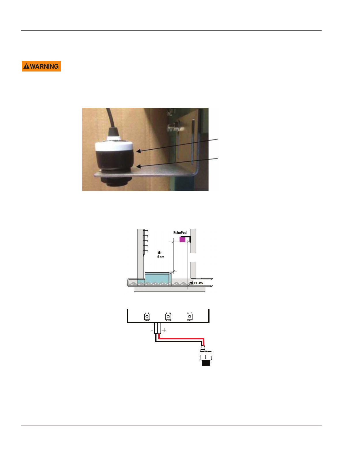
Installation the EchoPod DL-10 Sensor
Sensor EchoPod
Viton Gasket
1. Insert the gasket onto the threaded end of the sensor.
2. Screw the sensor into the stainless steel mounting bracket.
OTE:N Install the sensor at a maximum of 49.21 in. (125 cm) above the flume bottom (minimal measured level) with a
minimum of 1.97 in. (5 cm) distance above the maximal measured level.
Max
125 cm
3. Connect the sensor to the 4…20 mA input terminal on the bottom side of display board.
Page 8 December 2017HYB-UM-02509-EN-03
Page 9
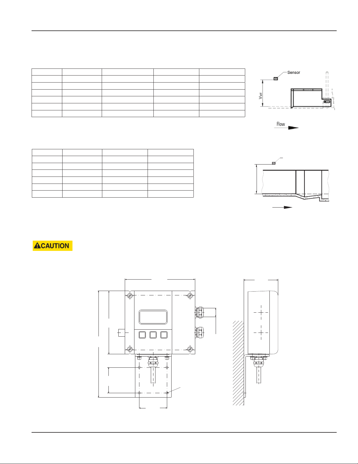
Mounting Positions
Manhole Flume
Size Max. Flow Max. Water Level V-Mt H-Mt
in. (DN) g/sec (l/sec) in. (mm) in. (mm) in. (mm)
4 (100) 1.32 (5) 5.83 (148) 23.62 (600) 5.75 (146)
6 (150) 4.23 (16) 8.94 (227) 23.62 (600) 7.75 (197)
8 (200) 9.25 (35) 12.28 (312) 23.62 (600) 9.76 (248)
10 (250) 16.64 (63) 15.55 (395) 27.56 (700) 11.73 (298)
12 (300) 24.83 (94) 18.00 (457) 27.56 (700) 13.74 (349)
Parshall Flume
Power Connections
Size Max. Flow V-Mt H-Mt
in. (DN) g/sec (l/sec) in. (mm) in. (mm)
Sensor
3 (75) 14.26 (54) 30.71 (780) 12.00 (305)
6 (150) 30.12 (114) 30.71 (780) 15.98 (406)
9 (230) 77.67 (284) 38.19 (970) 22.52 (572)
MT
V
12 (305) 157.98 (598) contact factory contact factory
18 (455) 24.83 (94) contact factory contact factory
POWER CONNECTIONS
FOR THE 2 × M20 CABLE INLETS, USE ONLY FLEXIBLE ELECTRIC CABLES. USE SEPARATE CABLE INLETS FOR AUXILIARY
POWER, SIGNAL AND INPUT/OUTPUT CABLES.
9.80 in.
(249 mm)
5.83 in.
(148 mm)
6.46 in.
(164 mm)
M20 (×2)
3.15 in.
(60 mm)
3.15 in.
(60 mm)
2.56 in.
(65 mm)
Ø 0.20 in.
(5.2 mm)
Page 9 December 2017 HYB-UM-02509-EN-03
Page 10
Power Connections
Auxiliary Power
• DO NOT CONNECT METER TO POWER SOURCE UNDER CONDITIONS THAT COULD CAUSE PERSONAL INJURY OR
DAMAGE TO THE EQUIPMENT.
• WIRING OF THIS EQUIPMENT MUST COMPLY WITH LOCAL AND NATIONAL CODES AND BE WITHIN THE VOLTAGE
AND FREQUENCY RATING LISTED ON THE METER.
• INSTALL EQUIPMENT WITH AN EXTERNAL MEANS FOR DISCONNECTING IT FROM POWER, SUCH AS A SWITCH OR A
CIRCUIT BREAKER.
1. Slightly loosen the lower cover screws.
2. Completely loosen both upper cover screws.
3. Open the cover to the lower side.
4. Push the auxiliary power cable through the upper cable inlet.
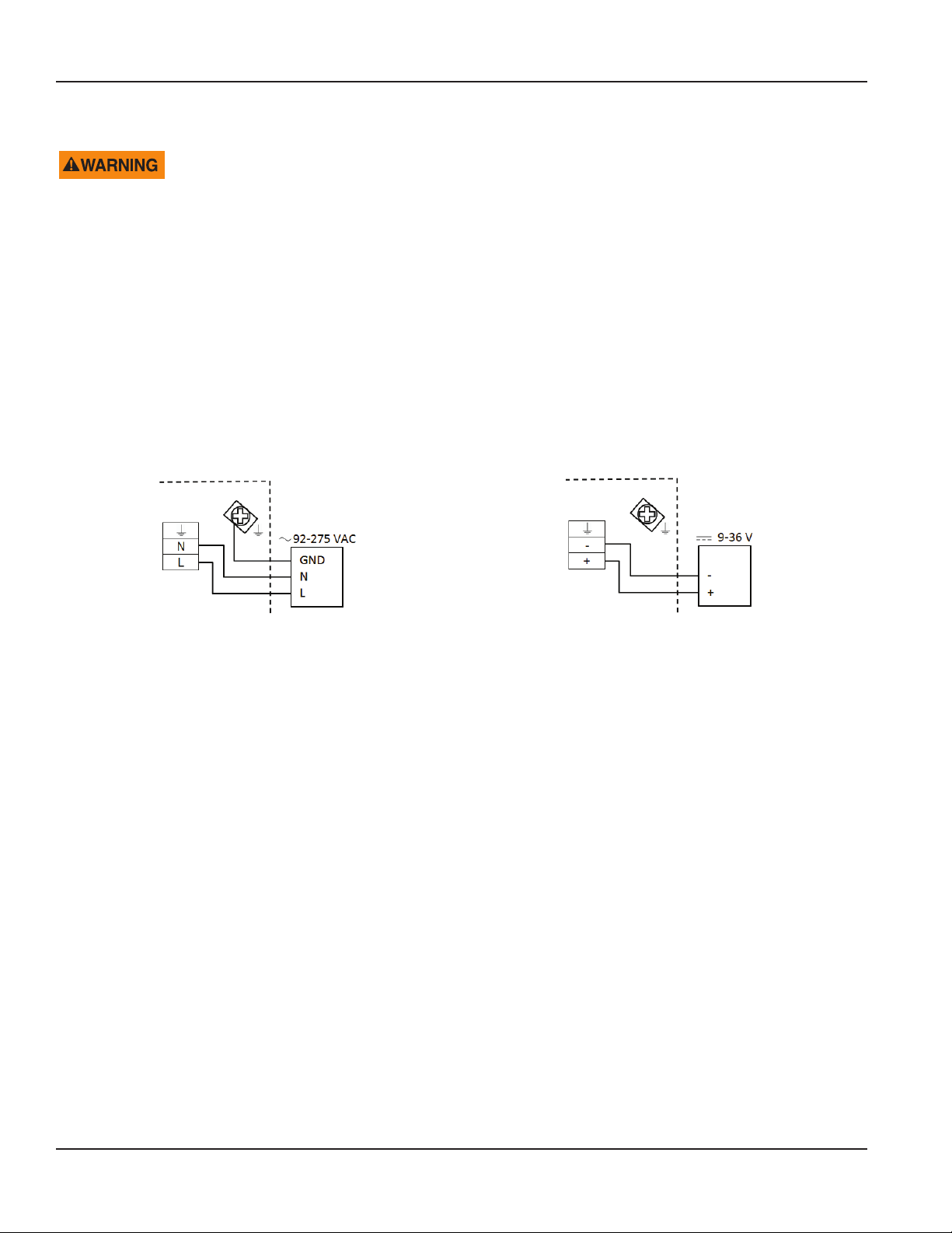
5. Connect the power as shown in Figure 1 or Figure 2, depending on the version (AC or DC) of meter you have.
6. Close the cover and tighten the four screws.
Figure 1: Power supply 92…275V AC (50/60 Hz);
recommended cable size min. 0.3 sq. in. (0.75 mm²)
Figure 2: Power supply 9…36V DC (max. 9 W);
recommended cable size min. 0.3 sq. in. (0.75 mm²)
Page 10 December 2017HYB-UM-02509-EN-03
Page 11
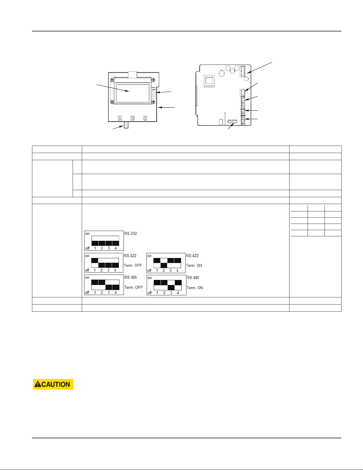
Conguring Input/Outputs (I/O)
Power Connections
Auxiliary Power
Display
Sensor Input
Ethernet
USB
RS-Interface
DIP switch
Solid-State
Relay
Digital
Output/Input
Analog Output
RS-Interface
Input/Output Description Terminal
Analog output* 0…20 mA, 4…0 mA, RL < 800 Ohm, 0…10 mA 7 (+), 8 (-), 9 (GND)
Digital output 1* Open collector max. 10 kHz, Passive max. 32V DC, <100 Hz 100 mA, >100 Hz 20 mA,
3 (-),4 (+)
Active 24V DC, 20 mA, (can be powered by analog output if not used)
2* Open collector max. 10 kHz, Passive max. 32V DC, <100 Hz 100 mA, >100 Hz 20 mA,
Active 24V DC, 20 mA, (can be powered by analog output if not used)
1 (-)
2 (+)
3 Solid-state relays max. 230V AC, 500 mA, max. 1 Hz (function is linked to Output 2) S1 and S2
Digital input* 5…30V DC 5 (-) and 6 (+)
RS interfaces* RS232, RS485 and RS422 with Modbus RTU.
Mode can be configured by DIP switches also termination ON or OFF. For the
RS485, connect the A wire to the Y terminal and the B wire to the Z terminal.
422 232 485
A RxD
B
Z TxD B
Y A
G (GND)
USB USB Device CDC (Host Mass Storage) Micro USB
Ethernet* Ethernet Interface connection RJ45 socket
* All marked inputs and outputs are according to safety data TNV-1 IEC 60950-1.
Input and Output Cable Connections
For the normal I/Os, use shielded cables. Connect the shield of the cable to one of the grounding screws. Recommended
cable is LiYCY size min. 0.06 sq. in. (0.14 mm²).
Solid-State Output
If using a second cable gland for the normal I/Os, use one cable and cable gland for the power supply and solid-state relay.
Recommended cable size is min. 0.3 sq. in. (0.75 mm²).
• USE SEPARATE CABLE INLETS FOR CABLES CONNECTED TO THE SOLID-STATE RELAY OUTPUT AND CABLES
CONNECTED TO THE OTHER INPUT/OUTPUTS.
• WITH MULTIPHASE POWER, SOLID-STATE RELAY SHOULD HANDLE ONLY THE SAME PHASE THAT IS USED FOR
POWERING THE METER.
Page 11 December 2017 HYB-UM-02509-EN-03
Page 12

Operation
OPERATION
Function Buttons
All programming is accomplished using the three function buttons on the front of the unit. Screen
navigation and digit and parameter selection is performed by a combination of these buttons.
Use the up-arrow to scroll through the menu screens or to advance numerical digits to change values.
Use the right-arrow to select digits from left to right and allows or to enter a submenu.
Use EXIT SAVE to save changed values, return to a previous menu or toggle between Measuring mode and Programing mode.
Display Icons
Minor battery power (Realtime clock) W Sensor warming
Device error 0 Sensor not connected
No keyword active M Sensor measuring
USB active S Simulation active
Menu Header
MainMenu
MeterSetup
Submenu
Indicates a Submenu
Scroll Bar
Initial Screens
From the Main Menu, press EXIT SAVE to display the current values and system information. The rst screen to display
depends on the application type (open channel or tank).
First screen for
open channel applications:
Parameter Value
Volume 305.6 m
Level 0.50 m
Flow 8.85 m
M
Unit of
Measure
3
3
/s
Icons
First screen for tank applications: Second screen for both applications.
Parameter Value
Unit of
Measure
Application
Version
Tag
Tag: iSonic 4000
1.2.00
Volume 50.3 m
Level 0.503 m
1
3
Icons
Date & Time
Parameter,
Value & Unit
2017-07-30 10:05
Current 10.184 mA
Page 12 December 2017HYB-UM-02509-EN-03
Page 13

Operation
Setting a PIN
The iSonic 4000 flow meter security feature allows the option to restrict access to the meter by way of a 6-digit Personal
Identification Number (PIN). The system administrator can set up a single PIN for each of the three different levels of access:
• Administration – allows access to all iSonic 4000 flow meter menu configuration screens.
• Service – allows access to service-level and user-level menu configuration screens.
• User – allows access only to user-level menu configuration screens.
OTE:N For a lost PIN, Contact Badger Meter Technical Support at 800-456-5023 for a replacement PIN.
Not all levels of access need to be set. If no PINs are set up, any user will have access to all functions.
1. From the Main Menu, press the right-arrow.
2. From the Meter Setup menu, press the up-arrow until the Pin menu is displayed.
3. Press the right-arrow to display the PINS Control menu.
4. Press the right-arrow to highlight ON or OFF.
5. With either ON or OFF highlighted, press the up-arrow to display ON.
6. Press EXIT SAVE to save the ON setting.
7. With the Control menu highlighted, press the up-arrow to display the required security level (user, service, or admin).
8. With the required security level highlighted, press EXIT SAVE to display the rst of six zeros (digits).
9. Press the up-arrow to change the rst digit, followed by pressing the right-arrow to select the next digit.
10. Press the EXIT SAVE button to save the PIN number for that security level.
Logging In
To change any parameter, the PIN entered must provide the proper security privilege required by the parameter.
To enter a PIN, go to the Login menu and enter the PIN for the required security level.
Once you are properly logged in, the unlocked icon appears on the meter display.
OTE:N A PIN Error message displays if the incorrect PIN is entered.
Logging Out
To log out, follow steps 1 through 8 under "Setting a PIN". At step 9, enter an invalid PIN, then press EXIT SAVE.
Page 13 December 2017 HYB-UM-02509-EN-03
Page 14

Programming
PROGRAMMING
Main Menu
From the Main Menu, you can access these submenus, each of which is described on the following pages:
• Meter Setup
• Measurements
• Input and Outputs
• Totalizer Reset
• Communication
• Miscellaneous
• Information
• Pin
The security levels are:
A
Administrative
S
Service
U
User
Parameters indicated by the battery icon, if changed, will affect battery performance.
To program the security levels, see "Setting a PIN" on page 13. No passwords were set at the factory.
Page 14 December 2017HYB-UM-02509-EN-03
Page 15

Meter Setup Menu
Programming
Application Tank
A
Open Channel
A
Sensor Interval
S
WarmUpTime
S
LowerRangeValue
A
UpperRangeValue
A
Offset
S
Select for a tank application.
Select for an open channel application.
Setup of time measurement interval(s); default value is 1 second; larger
interval (for instance, 300 seconds) is set when unit is powered from
battery
Powering time of sensor(s) before measurement; larger interval is set
when unit is powered from battery
The minimum level value of used sensor = 4 mA in selected level units
The maximum level value of used sensor = 20 mA in selected level units
Level offset in selected level units, depends of sensor mounting position
Page 15 December 2017 HYB-UM-02509-EN-03
Page 16

Programming
Measurement Menu
Length
U
Flow Rate
U
Volume
U
Establishes the unit of measure for the length
Display Length Unit
ft Feet
m Meter
in. Inch
cm Centimeter
mm Millimeter
DecimalPlaces – set of the decimal places of the Length values
Establishes the unit of measure for the flow rate
Display Flow Unit Display Flow Unit
L/s Liters/Second gal/s Gallons/Sec.
L/min Liters/Minute gal/min Gallons/Min.
L/h Liters/Hour gal/h Gallons/Hour
m3/s Cubic Meters/Sec. MG/d MillionGallons/Day
m3/min Cubic Meters/Min. IG/s ImperialGallons/Sec.
m3/h Cubic Meters/Hour IG/min ImperialGallons/Min.
ft3/s Cubic Feet/Sec. IG/h ImperialGallons/Hour
ft3/min Cubic Feet/Min. Bbl/min Barrel/Min
ft3/h Cubic Feet/Hour.
DecimalPlaces – set of the decimal places of the Flow Rate values
Display Volume Unit Display Volume Unit
L Liters MG MegaGallons
hL HectoLiter IG Imperial Gallons
m3 Cubic Meters bbl Barrel
3
Ft
gal US Gallons
DecimalPlaces – set of the decimal places of the Volume values
Cubic Feet Aft Acre Feet
Page 16 December 2017HYB-UM-02509-EN-03
Page 17

Equation SelectionAQ/h Table selection is possible only from the Flow Meter Tool software
Display Description
Exponential Eq Exponential Function Q = K h
exp
Contract.Weir Contracted Weir
Suppress.Weir Suppressed Weir
CipolettiWeir Cipoletti Weir
VNotchWeir30° V Notch Weir 30°
VNotchWeir45° V Notch Weir 45°
VNotchWeir60° V Notch Weir 60°
VNotchWeir90° V NotchWeir 90°
ManningRect. Manning Rectangle Flume
ManningPipe Manning Pipe
Pars.Flume1" Parschall Flume 1"
Pars.Flume2" Parschall Flume 2"
Pars.Flume3" Parschall Flume 3"
Pars.Flume6" Parschall Flume 6"
Pars.Flume9" Parschall Flume 9"
Par.Flume12" Parschall Flume 12"
Par.Flume18" Parschall Flume 18"
Par.Flume24" Parschall Flume 24"
Par.Flume36" Parschall Flume 36"
Par.Flume48" Parschall Flume 48"
Par.Flume60" Parschall Flume 60"
Manh.Flume4" Manhole Flume 4"
Manh.Flume6" Manhole Flume 6"
Manh.Flume8" Manhole Flume 8"
Manh.Flume10" Manhole Flume 10"
Manh.Flume12" Manhole Flume 12"
Equation Params
Exponent value in for equation (Q= K h exp) Exponent
Coefficient value in for equation (Q= K h exp) Coefficient
A
Measured profile width (Weirs, Manning equation) Width
Rectangular profile slopes angle (Manning equation) Angle
Measured pipe Radius (Manning equation) Radius
Water Surface Slope (Manning equation) WaterSurfaceSlope
Surface Roughness coefficient (Manning equation) SurfaceRoughness
Maximum Water Level MaximumWaterLevel
Flow Rate Upper Range Value UpperRangeValue
Maximum Water Level /SetDefaultVal.
Set of the Maximum Water Level for the selected primary element – the value is possible to
edit further.
Upper Range Value /Calculate
Is calculating the maximal Flow Rate value for Maximal Water Level - the value is possible to edit
further – this parameter is used also for outputs (Upper Range Value=100% - full range)
Programming
Page 17 December 2017 HYB-UM-02509-EN-03
Page 18

Programming
Open Channel Calculation
Volumetric flow is calculated from actual water level. Actual water level is limited by the maximum water level.
The Exponential Equation for general Parshall or Manhole flume: Q=K.Q
exp
Q – Volumetric flow [m³/s]
K – Coefficient [m
(3-n)
/s]
h – Water level [m]
exp – Exponent [-]
Predefined Flume Equation [m³/s, m] Max. Water Level [m]
Parshall flume 1 in. Q = 0.0604 • h
Parshall flume 2 in. Q = 0.1207 • h
Parshall flume 3 in. Q = 0.1771 • h
Parshall flume 6 in. Q = 0.3810 • h
Parshall flume 9 in. Q = 0.5350 • h
Parshall flume 12 in. Q = 0.7050 • h
Parshall flume 18 in. Q = 1.0670 • h
Parshall flume 24 in. Q = 1.4290 • h
Parshall flume 36 in. Q = 2.1900 • h
Parshall flume 48 in. Q = 2.9600 • h
Parshall flume 60 in. Q = 3.7500 • h
Manhole flume 4 in. Q = 0.2343 • h
Manhole flume 6 in. Q = 0.3026 • h
Manhole flume 8 in. Q = 0.3424 • h
Manhole flume 10 in. Q = 0.3868 • h
Manhole flume 12 in. Q = 0.4345 • h
1.55
1.55
1.55
1.55
1.55
1.55
1.55
1.55
1.57
1.58
1.59
1.95
1.95
1.95
1.95
1.95
0.230
0.260
0.667
0.724
0.876
0.925
0.925
0.925
0.925
0.925
0.925
0.149
0.227
0.313
0.396
0.457
Contracted rectangular weir
Equation Q = 1.84 • (L - 0.2 • h) • h
1.5
Q – Volumetric flow [m³/s]
1.84 – Coefficient [√m/s]
L – Width [m]
h – Water level [m]
Suppressed rectangular weir
Equation Q = 1.84 • L • h
1.5
Q – Volumetric flow [m³/s]
1.84 – Coefficient [√m/s]
L – Width [m]
h – Water level [m]
Cipoletti rectangular weir
Equation Q = 1.84 • L • h
1.5
Q – Volumetric flow [m³/s]
1.84 – Coefficient [√m/s]
L – Width [m]
h – Water level [m]
V-notch weir 30°
2
Equation Q=8√ • tan
12
2 • g
30
2
(
)
Q – Volumetric flow [m³/s]
g – Standard gravity 9.80665 [m/s2]
h – Water level [m]
• 0.586 • (h + 0.0021)
2.5
Page 18 December 2017HYB-UM-02509-EN-03
Page 19

V-notch weir 45°
2
Equation Q=8√ • tan
Q – Volumetric flow [m³/s]
g – Standard gavity 9.80665 [m/s2]
h – Water level [m]
V-notch weir 60°
Equation Q=8√ • tan
Q – Volumetric flow [m³/s]
g – Standard gavity 9.80665 [m/s2]
h – Water level [m]
V-notch weir 90°
Equation Q=8√ • tan
Q – Volumetric flow [m³/s]
g – Standard gavity 9.80665 [m/s2]
h – Water level [m]
12
12
12
2 • g
2 • g
2 • g
45
2
(
2
60
2
(
2
90
2
(
• 0.580 • (h + 0.0015)
)
• 0.577 • (h + 0.0012)
)
• 0.578 • (h + 0.0008)
)
Programming
2.5
2.5
2.5
2/3
2/3
)
)
2
2
1/2
I
A Rh=A/P
• √I• h • L +
2/3
• √ I •
| h > r
)
| h ≤ r
)
Manning equation: Q = 1/n Rh
Manning rectangular
Equation Q =
1
n
(
Q – Volumetric flow [m³/s]
n – Gauckler-Manning coefficient [s/3√m]
L – Width [m]
h – Water level [m]
a – Angle [°]
I – Water surface slope [m/m]
Manning pipe
Equation Q =
2 • π - 2 • arcsin
a =
2 • arcsin
Q – Volumetric flow [m³/s]
n – Gauckler-Manning coefficient [s/3√m]
L – Width [m]
h – Water level [m]
I – Water surface slope [m/m]
(a - sina) • r
1
(
n
(
(
2
h
tga
h • L+
2 • h
+L
sina
2 a 2
2 • h • r - h
√
r
√
2 • h • r - h
r
(a - sina) • r
(
2
h
( )
tga
2
)
where
Material n = s/3√m Material n = s/3√m Material n = s/3√m
Glass , PVC 0.010 Gravel, firm 0.023 Natural channels, poor 0.060
Cement, concrete, steel 0.011 Earth channel, gravelly 0.025 Floodplains, heavy brush 0.075
Brick 0.015 Earth channel, weedy 0.030 Floodplains, trees 0.150
Earth, smooth 0.018 Natural streams, clean 0.035
Earth channel, clean 0.022 Floodplains, light brush 0.050
Page 19 December 2017 HYB-UM-02509-EN-03
Page 20

Programming
Input/Outputs Menu
Analog Output Range
S
Alarm Mode
S
Compensation
Establishes the range of the analog output signal: 0…100% (= full scale). The
following current output ranges are available:
• 0…20 mA
• 4…20 mA
• 0…10 mA
Analog output active
Analog output passive
OTE:N If an error message displays, set the current according the
programing of the Alarm Mode below. When you select bidirectional
operation, you can signal the flow direction via digital outputs.
This parameter configures the behavior of the analog output during alarm
conditions. The options are OFF, 3.5 mA and 23 mA.
• OFF: Analog signal is based on flow rate and always within the
configured range.
• 3.5 mA: During alarm conditions, the analog signal is 3.5.
• 23 mA: During alarm conditions, the analog signal is 23 mA.
For example, if the analog range is 4…20 mA and the alarm mode is set
to 23 mA, then during a full scale flow alarm condition, the analog output
current will be 23 mA.
Correction of the current value output.
S
Digital Input
Digital input lets you reset totalizers (remote reset), interrupt flow measurement (PosZeroReturn) or
ADE. Input switching is provided by applying an external potential of 5…30V DC
S
or by an internal voltage source of 24V DC (analog output if not used).
Page 20 December 2017HYB-UM-02509-EN-03
Page 21

Digital Outputs You can configure functional operation of the 2 digital outputs. For example, you can select
Forward Pulse for the digital output and define the pulses per totalizer unit via pulse scale.
Digital Outputs 1 and 2SThe two outputs can be operated as open collector passively or actively.
Passive output
Active output (if analog output is not used)
Programming
Solid-State Relay
S
The solid-state relay is functionally linked with Output 2.
See "Out 1 / 2 Function" below.
Page 21 December 2017 HYB-UM-02509-EN-03
Page 22

Programming
Digital Outputs Pulse Width
S
Pulse/Unit
S
Out 1 /2 Function
S
Output 1 /2 Type
This parameter establishes the ON duration of the transmitted pulse. The
configurable range is from 0…2000 ms. If 0 ms is configured, pulse width is
automatically adapted depending on pulse frequency
(pulse/pause ratio 1:1).
During the configuration the program checks if pulses/unit and pulse width
are in accordance with full scale defined. If not, an error alarm displays and
scale, pulse width or full scale need to be adapted.
The Pulses/Unit parameter lets you set how many pulses per unit of measure
to transmit. The maximum output frequency of 10,000 pulses/sec. (10 kHZ)
must not be exceeded.
The following functions can be selected for the Output 1, Output 2 and the
Solid-State Relay. The Solid-State Relay function is linked functionally with
Output 2.
Function Out1 Out2 / Solid-State Relay
Off X X
Forward pulse X X
Min/Max Alarm X X
Error alarm X X
Pump Control X X
Test X X
ADE X
• OFF: Digital output is switched off.
• Forward pulse: Generates pulses during forward flow conditions.
• Min/Max Alarm: Indicates when flow rate exceeds thresholds defined by
Set Min. or Set Max. in % of full scale. See “Figure 3: Tank volume or open-
channel flow rate” on page 23.
• Error alarm: Indicates when the meter has error an condition.
• Pump Control: Starts or stops the pump. See “Figure 3: Tank volume or
open-channel flow rate” on page 23.
• Test: Used only for the Verification Device.
• ADE: Used for BEACON and AquaCUE connectivity.
The output type parameter lets you set the output switch to “normally
closed“ or “normally open“.
S
Output 1 /2 Set Min
S
Output 1 /2 Set MaxSThe Flow Max Set Point establishes, as a percentage of full scale flow, the
Flow SimulationSFlow Simulation provides analog and digital output simulation based on a percentage of the full scale
flow in cases where no real flow is occurring. The range of simulation includes 0…100% in steps of 10%
of the full scale flow. This function remains active when you exit the menu. You must set it to Off to
deactivate it. If the simulation is still active, a character “S” displays in the Measuring mode.
The flow Min Set Point establishes, as a percentage of full scale flow, the
minimum threshold at which the output alarm activates. Select thresholds in
1% steps. Flow rates below or above the threshold activate the output alarm.
maximum threshold at which the output alarm activates. Select thresholds in
1% steps. Flow rates below or above the threshold activate the output alarm.
Page 22 December 2017HYB-UM-02509-EN-03
Page 23

Programming
Clear Total
Total
A
Figure 3: Tank volume or open-channel flow rate
Resets the totalizer within the ClearTot item on the Flow Meter Tool software.
Page 23 December 2017 HYB-UM-02509-EN-03
Page 24

Programming
Communications Menu
Interfaces Modbus® RTU RS232, RS485 and RS422 with Modbus RTU.
Mode can be configured by DIP switches also if termination ON or OFF.
Modbus Address Address available from 1…247
RS232, RS422, RS485 Baudrate: 1200, 2400, 4800, 9600, 19200, 38400 Bd
Parity: Even, Odd, Mark, Received Packets, Sent Packets
Ethernet Modbus TCP/IP with MEAP-Header
IP Address IPv4 address default 192.168.1.60
IP Mask IPv4 subnetting reference default 255.255.255.0
IP Gateway Gateway address default 192.168.1.1
MAC Address Media-Access-Control-Address
ADE Control ON or OFF
Protocol 1 or 2
Dial 4…9
Resolution 0.001 / 0.01 / 0.1 / 1 / 10 / 100 / 1000 / 10,000
Miscellaneous
Power up The number of times that the unit has been powered on.
Language The unit supports these languages: English, German, Czech, Spanish, French, Russian
Date Set the system date in the format [DD.MM.YY]; used for data logging.
Time Set the system time in the format [HH.MM.SS]; used for data logging.
Contrast The contrast of the display can be adjusted between 14 (low) and 49 (high).
Datalog Period The data logging period can be adjusted to every 10 min / 20 min / 30 min / 1 h / 24 h.
There is a 2 MB memory with about 130,000 data records for data logging available. The logging
capacities (uni-directional mode) and durations are:
10 min up to 2.50 years
20 min up to 5 years
30 min up to 7.5 years
1 h up to 15 years
24 h up to 260 years
The logging information can be downloaded by a PC program Flow Meter Tool.
Page 24 December 2017HYB-UM-02509-EN-03
Page 25

Programming
Info Menu
Serial Number Serial number of the electronic board.
Version Software version of the device.
Compilation Date Date of the software version.
Otp CRC Checksum of software update
Application CRC Checksum of application
PIN Menu
The menus and parameters can be secured via three password levels. See "Setting a PIN" on page 13.
• Administrator PIN
• Service PIN
• User PIN
The password protection is a 6-digit PIN [000000] and is deactivated at the factory.
The first time you use the unit, activate the password protection Control = On and enter login with the password 000000.
Then go back to the PIN again and enter [User], [Service] and [Admin] password.
Once the password protection has been activated, enter your PIN under Login and the lock open symbol appears.
The PIN grants you access to Administrator, Service or User levels with the respective access rights. You can now move to the
menu and enter parameters.
Without a login, you can read all parameters, but cannot change them.
Control Activate and deactivate the PIN
User User logged in with this PIN can access all User levels, but do not have access to Service or
Admin functions.
Service User logged in with this PIN will have access to both service and user-level procedures. User at this
level will not have access to administrative functions.
Admin User logged in with this PIN will have access to both service and user-level procedures.
Random Number In case of losing PIN read the random number. This number has to be sent to Badger Meter support,
which is able to generate the Emergency PIN. Between reading random number and entering received
emergency PIN, do no try to play with emergency PIN and do not restart the meter.
Emergency PIN In case of losing PIN read the random number. This number has to be sent to Badger Meter support,
which is able to generate the emergency PIN. Between reading random number and entering received
emergency PIN, do no try to play with emergency PIN and do not restart the meter.
Login Menu
Login Once the password protection has been activated, enter your PIN.
Page 25 December 2017 HYB-UM-02509-EN-03
Page 26

Main Board
LED1
LED2
LED3
LED10
Troubleshooting
TROUBLESHOOTING
The following error messages may display:
Description Possible Cause Recommended Action
Pulse Output Pulse rate exceeds the maximum
EEPROM Configuration file is missing Contact support
Configuration Configuration file is corrupted Contact support
Low Battery Low backup battery (memory) Contact support
Measure
Timeout
Measurement was not completed within specific time Contact support
Control LED
Reduce pulse scale (pulse/unit) and/or reduce
pulse width configuration
LED 7
LED 6
LED 8
Display Board
LED 13
LED 5
The following LEDs on the board control the operation of the device:
LED1 No function attached
LED3 Communication – transmit (On = active)
LED5 Flash memory activity (DISK)
LED6 Digital output #1 (On = active)
LED7 Digital output #2 (On = active)
LED8 No function attached
LED10 Power ON (On = active)
LED13 USB, HOST mode (On = active)
Replace Meter’s Electronics
DISCONNECT AUXILIARY POWER BEFORE OPENING THE BODY COVER.
1. Pull out all the plugs.
2. Loosen screws S1-S4 and take out circuit board.
3. Insert the new circuit board and attach it by fastening the screws S1-S4.
4. Plug in all plugs.
5. If necessary, congure the new board.
Page 26 December 2017HYB-UM-02509-EN-03
Page 27

SPECIFICATIONS
Type iSonic 4000
Auxiliary power 92…275V AC (50/60 Hz), < 14 VA optional 9…36V DC, < 4 W
Analog output
Level sensor input 4…20 mA from level sensor
Digital outputs
Digital input 5…30V DC; totalizer reset, positive return zero, BEACON/AquaCUE connectivity
Programming port Mini USB, IP67
Configuration 3 front-panel mounted push-buttons
Communication RS485 Modbus RTU, Modbus TCP/IP Ethernet, BEACON/AquaCUE connectivity
Pulse length Configurable up to 2000 msec
Datalogger 2 MB capacity with 130,000 logged lines: date, level, flow rate, tank volume
Display Graphical LCD 64 × 128, backlight, actual flow rate, totalizers, status display
Body Die cast powder-coated aluminium, protection class IP67
Cable inlet Supply and signal cables 2 × M20; cable glands included
Signal cable From meter M20; cable gland included
Ambient
temperature
Sensors
Security Three level password
Languages English, Spanish, French, German, Italian, Czech, Russian
Channel selection
4…20 mA, 0…20 mA, 0…10 mA ≤ 800 Ohm, active or passive; Assigned parameter depends on flow
meter mode
2 open collectors; passive: max. 32V DC, 0…100 Hz 100 mA, 100…10.000 Hz 20 mA; active: 24V DC,
max 20 mA; Select active pulse, min/max alarm, error messages or pump control
Solid-state relay (n.o./n.c.) max 230V AC, 500 mA, 1 Hz; Function is linked with open collector output 2
-20…60° C
Measuring
range
4. 92 in.
(0…1250 mm)
Contracted rectangular weir, suppressed rectangular weir, Cipoletti weir; V-notch weir (30°, 45°, 60°,
90°); Parshall flume (1, 2, 3, 6, 9, 12, 18, 24, 36, 48 and 60 in.); Manhole flume (4, 6, 8, 10 and 12 in.);
table entry, exponential equation, Manning rectangle flume, Manning pipe
Offset Beam width Material Accuracy Deadband
2 in.
(50 mm)
2 in.
(50 mm)
PVDF
0.125 in.
(3 mm)
Specications
2 in.
(50 mm)
Page 27 December 2017 HYB-UM-02509-EN-03
Page 28

Dimensions
DIMENSIONS
9.80 in.
(249 mm)
5.83 in.
(148 mm)
3.15 in.
(60 mm)
6.46 in.
(164 mm)
Ø 0.20 in.
(5.2 mm)
2.56 in.
(65 mm)
Figure 4: iSonic 4000 flow computer
M20 (×2)
3.15 in.
(60 mm)
0.44 in.
(11.20 mm)
(57.00 mm)
2.24 in.
0.43 in.
(11.00 mm)
11°
0.38 in.
(9.60 mm)
(53.29 mm)
0.38 in. (9.7 mm)
R3
(101.50 mm)
2.10 in.
Ø 1.34 in.
(34.0 mm)
4.00 in.
0.38 in.
(9.60 mm)
R3
1.00 in.
(25.3 mm)
11°
0.43 in.
(11.00 mm)
5.00 in.
(127 mm)
R8
2.00 in.
(76.00 mm)
0.19 in.
(3.00 mm)
Figure 5: Sensor bracket
Page 28 December 2017HYB-UM-02509-EN-03
Page 29

Main Menu Program Structure
MAIN MENU PROGRAM
STRUCTURE
Meter Setup
Application Tank
Open Channel
Sensor Interval
Warm Up Time
Lower Range Value
Upper Range Value
Offset
Measurements
Length Unit ft
m
in
cm
mm
Decimal Places
Flow Rate Unit L/s
L/min
L/h
m³/s
m³/min
m³/h
ft³/s
ft³/min
ft³/h
gal/s
gal/min
gal/h
MG/D
IG/s
IG/min
IG/h
bbl/min
Decimal Places
Volume Unit L
hL
m³
ft³
gal
MG
IG
bbl
Aft
Decimal Places
Measurements (continued)
Equation Selection Table
Exponential Eq
Contract. Weir
Suppress. Weir
Cipoletti Weir
V NotchWeir30°
V NotchWeir45°
V NotchWeir60°
V NotchWeir90°
Manning Rect.
Manning Pipe
Pars. Flume 1"
Pars. Flume 2"
Pars. Flume 3"
Pars. Flume 6"
Pars. Flume 9"
Par. Flume 12"
Par. Flume 18"
Par. Flume 24"
Par. Flume 36"
Par. Flume 48"
Par. Flume 60"
Manh. Flume 4"
Manh. Flume 6"
Manh. Flume 8"
Manh. Flume 10"
Manh. Flume 12"
Equation Params Exponent
Coefficient
Width
Angle
Radius
Water Surface Slope
Surface Roughness
Max. Water Level SetDefaultVal.
Exit
Max. Water Level
Upper Range Value Calculate
Exit
Page 29 December 2017 HYB-UM-02509-EN-03
Page 30

Main Menu Program Structure
Inputs/Outputs
Analog Output Select Range 4…20 mA
0…20 mA
0…10 mA
Alarm Mode Off
23 mA
3.5 mA
Compensation
Digital Input Off
Remote Reset
Pos Zero Reset
ADE
Digital Output Pulse Width
Pulse/Unit
Out 1 function Off
Forward Pulses
Min/Max Alarm
Error Alarm
Test
Pump Control
ADE
Out 1 Type Normally Open
Normally Close
Out 1 Set Min
Out 1 Set Max
Out 2 Function Off
Forward Pulses
Min/Max Alarm
Error Alarm
Test
Pump Control
Out 2 Type Normally Open
Normally Close
Out 2 Set Min
Out 1 Set Min
Simulation Off
+100.0%
+90%
+80%
+70%
+60%
+50%
+40%
+30%
+20%
+10%
0.0%
Total
Total Clear Tot
Exit
Communications
Modbus MODBUS Address
RS-232/422/485 Baud Rate 1200
2400
4800
9600
19200
38400
115200
Parity Even
Odd
Ethernet Received Packets
Sent Packets
IP Address
IP Gateway
MAC Address
ADE Control On
Off
Protocol 1
2
Dial 4…9
Resolution 0.0001…10000
Miscellaneous
Power up
Language English
German
Czech
Spanish
French
Russian
Date [DDMMYY]
Time [HHMMSS]
EEPROM Format
Exit
Contrast
Datalog Period 10 min
20 min
30 min
1 h
24 h
Info
Serial Number
Version
Compilat. Date
Otp CRC
Applicat. CRC
Pin
Control
User
Service
Admin
Random Number
Emergency PIN
Login
Login
Page 30 December 2017HYB-UM-02509-EN-03
Page 31

Flow Meter ModBus® Register Table
FLOW METER MODBUS® REGISTER TABLE
Address Registers Rights Name iSonic
0x0000 U16 Read only PRODUCT_CODE 7: iSonic
0x0001 8 Read only PRODUCT_NAME “iSonic 4000”
0x0009 16 Read only FW_NAME "iSonic_A_STM32F107RC"
0x0019 10 Read only APP_VERSION Version
0x0023 16 Read only COMPILATION_DATE Date of compilation
0x0033 16 Read only COMPILATION_TIME Time of compilation
0x0043 5 Factory IDENTIFICATION_NUMBER Unique number
0x0048 3 Read only OTP_BOOT_CHECKSUM Checksum
0x004B 3 Read only FLASH_OS_CHECKSUM Checksum
0x0081 U16 User POWER_LINE_FREQUENCY
0x0095 U16 Service ANALOG_OUTPUT_RANGE
0x00A1 U16 Service OUT1_LOW Digital Output setting
0x00A2 U16 Service OUT1_HIGH Digital Output setting
0x00A3 U16 Service OUT1_MODE
0x00A4 U16 Service OUT1_OPERATION
0x00AE U16 Service OUT2_LOW Digital Output setting
0x00AF U16 Service OUT2_HIGH Digital Output setting
0x00B0 U16 Service OUT2_MODE
0x00B1 U16 Service OUT2_OPERATION
0x0114 U16 User LANGUAGE
0x0115 Float Read only MEASURE Dry calibration
0x0119 U16 Read only MEASURE_COUNTER Dry calibration
0: 50 Hz
1: 60 Hz
1: 4…20 mA
2: 0…20 mA
3: 0…10 mA
0 normally open
1 normally closed
0: Off
1: Comparator
3: Error alarm
4: Forward
10: Test
14: Pump
0 normally open
1 normally closed
0 Off
1 Min/Max Alarm
3 Error alarm
4 Forward pulses
10 Test
14 Pump control
0 English
1 German
2 Czech
3 Spanish
4 French
5 Russian
6 Italian
7 Turkish
Page 31 December 2017 HYB-UM-02509-EN-03
Page 32

Flow Meter ModBus® Register Table
Address Registers Rights Name iSonic
1: save configuration
2: restore configuration
6: save totalizers
7: clear totalizers
8: clear totalizers
14: current loop calibration point A
15: current loop calibration point B
16: current loop calibration complete
22: default save
0x0125 U16 Admin COMMAND
23: remote reset
24: default restore
26: make file system
34: press key up
35: press key right
36: press key save exit
38: print screen
41: open channel – calculate upper
range
42: open channel – use default water
level
0x0126 Float Factory CURRENTLOOP_POINTA Dry calibration
0x0128 Float Factory CURRENTLOOP_POINTB Dry calibration
Not stored in non-volatile memory 0:
0.0%
10: + 10.0%
20: + 20.0%
30: + 30.0%
40: + 40.0%
50: + 50.0%
60: + 60.0%
70: + 70.0%
80: + 80.0%
90: + 90.0%
0x012A U16 Service SIMULATION
100: +100.0%
65408: Off
65436: -100.0%
65446: - 90.0%
65456: - 80.0%
65466: - 70.0%
65476: - 60.0%
65486: - 50.0%
65496: - 40.0%
65506: - 30.0%
65516: - 20.0%
65526: - 10.0%
0x012B U32 Read only RANDOM Security
0: none
0x012E U16 Service ALARM_MODE_OF_ ANALOG_OUTPUT
3: 23 mA
4: 3.5 mA
0x012F U32 Write only REMOTE_LOGIN Security
0x0202 Float Service PULSE_PULSES_PER_M3 Digital Output setting
0x0204 U16 Service PULSE_WIDTH Digital Output setting
0x0205 U16 Service OUT_LOW OBSOLETE
Page 32 December 2017HYB-UM-02509-EN-03
Page 33

Flow Meter ModBus® Register Table
Address Registers Rights Name iSonic
0x0206 U16 Service OUT_HIGH OBSOLETE
0x0226 6 Service DATETIME Date & Time
Bit0: Low Battery
Bit1: Measure Timeout
Bit2: Table Error
Bit6: Flow Overload Warning
0x0232 U16 Read only FAULT
Bit7: Disk Error
Bit8: Configuration Error
Bit9: Pulse Overload Warning
Bit10: Sensor Disconnected Error
Bit11: Sensor Shorted Error
0x0233 8 Read only PORT Debug information
0x023D U16 Admin PASSWORD_CONTROL Security
0x023E 4 User PASSWORD_SET_USER Security
0x0242 4 Service PASSWORD_SET_SERVICE Security
0x0246 4 Admin PASSWORD_SET_ADMIN Security
0x025B U64 Read only FS_TOT Internal Disk Size [byte]
0x025F U64 Read only FS_FRE Internal Disk Free Space [byte]
10: 10 min
20: 20 min
0x0263 U16 Service DATALOGGER_PERIOD
30: 30 min
61: 1 hour
84: 24 hour
0x0267 U16 Service MEDIAN Filter setting
0x0268 U16 Service MOVING_AVERAGE Filter setting
0x0279 Float Read only ANALOG_OUTPUT_K Dry calibration
0x0281 Float Read only ANALOG_OUTPUT_Q Dry calibration
0x02B3 Float Service ANALOG_OUTPUT_ COMPENSATION Analog Output Compensation
0x02E3 U32 Read only POWER_UP_COUNTER Power up counter
0x0300 U16 Admin DATAPROCESSING_TANK_ OPENCHANNEL
0 Tank
1 Open Channel
44 Feet
45 Meters
0x0301 U16 User UNITCODES_LENGTH
47 Inches
48 Centimeters
49 Millimeters
15 Cubic Feet Per Minute
16 Gallons Per Minute
17 Liters Per Minute
18 Imperial Gallons Per Minute
19 Cubic Meter Per Hour
22 Gallons Per Second
23 Million Gallons Per Day
24 Liters Per Second
0x0302 U16 User UNITCODES_ VOLUMETRICFLOW
26 Cubic Feet Per Second
28 Cubic Meters Per Second
30 Imperial Gallons Per Hour
130 Cubic Feet Per Hour
131 Cubic Meters Per Minute
133 Barrels Per Minute
136 Gallons Per Hour
137 Imperial Gallons Per Second
138 Liters Per Hour
Page 33 December 2017 HYB-UM-02509-EN-03
Page 34

Flow Meter ModBus® Register Table
Address Registers Rights Name iSonic
40 Gallons
41 Liters
42 Imperial Gallons
43 Cubic Meters
0x0303 U16 User UNITCODES_VOLUME
46 Barrels
112 Cubic Feet
236 Hectoliters
240 Mega Gallons
241 Acre Feet
0x0304 U16 User DECIMALPLACES_LENGTH Number of decimal places of length
0x0305 U16 User DECIMALPLACES_ VOLUMETRICFLOW
Number of decimal places of
volumetric flow
0x0306 U16 User DECIMALPLACES_VOLUME Number of decimal places of volume
0: Open Channel Table
3: Contracted Rectangular Weir
4: Suppressed Rectangular Weir
5: Cipoletti Weir
7: Manning Equation Rectangular
Channel
8: Manning Equation Pipe
9: V Notch Weir 30°
10: V Notch Weir 45°
11: V Notch Weir 60°
12: V Notch Weir 90°
13: Parshall Flume 1"
14: Parshall Flume 2"
0x0307 U16 Admin OPENCHANNEL_EQUATION
15: Parshall Flume 3"
16: Parshall Flume 6"
17: Parshall Flume 9"
18: Parshall Flume 12"
19: Parshall Flume 18"
20: Parshall Flume 24"
21: Parshall Flume 36"
22: Parshall Flume 48"
23: Parshall Flume 60"
24: Manhole Flume 4"
25: Manhole Flume 6"
26: Manhole Flume 8"
27: Manhole Flume 10"
28: Manhole Flume 12"
29: Exponential Equation
0x0308 Float Admin SENSOR_ UPPERRANGEVALUE Sensor description [m]
0x030A Float Admin SENSOR_ LOWERRANGEVALUE Sensor description [m]
0x030C Float Factory SENSOR_ DIVISIONTOCURRENT_K Dry calibration
0x030E Float Factory SENSOR_ DIVISIONTOCURRENT_Q Dry calibration
0x0310 Float Read only SENSOR_WATERLEVEL Actual water level
0x0312 Float Read only DATAPROCESSING_ OPENCHANNELFLOW Actual volumetric flow
0x0314 Float Read only DATAPROCESSING_TANKVOLUME Actual tank volume
0x0316 Float Read only TOTALIZER Totalizer
0x0318 Float Read only SENSOR_CURRENT Sensor actual current
0x031A Float Service OPENCHANNEL_ UPPERRANGEVALUE Open channel description
0x031C Float Service TANK_ UPPERRANGEVALUE Tank description
0x031E U16 Service MEASURE_WARMUPTIME Sensor setting
0x031F U16 Service MEASURE_INTERVAL Sensor setting
Page 34 December 2017HYB-UM-02509-EN-03
Page 35

Flow Meter ModBus® Register Table
Address Registers Rights Name iSonic
0x0320 16 User DESIGNATION_CURRENT UTF-8 Designation of sensor current
0x0330 16 User DESIGNATION_ WATERLEVEL UTF-8 Designation of water level
0x0340 16 User DESIGNATION_FLOW UTF-8 Designation of flow
0x0350 16 User DESIGNATION_VOLUME UTF-8 Designation of volume
0x0360 32 User DESIGNATION_TAG UTF-8 Designation of device
0x0380 Float Service SENSOR_ WATERLEVELOFFSET Offset
0x0388 Float Admin SENSOR_ UPPERRANGEVALUE_ ACTUALUNIT Sensor description
0x038A Float Admin SENSOR_ LOWERRANGEVALUE_ ACTUALUNIT Sensor description
0x0390 Float Read only SENSOR_WATERLEVEL_ ACTUALUNIT Actual water level
0x0392 Float Read only
0x0394 Float Read only DATAPROCESSING_ TANKVOLUME_ACTUALUNIT Actual tank volume
0x0396 Float Read only TOTALIZER_ACTUALUNIT Totalizer
0x0398 Float Service SENSOR_ WATERLEVELOFFSET_ ACTUALUNIT Offset
0x039A Float Service
0x039C Float Service TANK_U PPERRANGEVALUE_ ACTUALUNIT Tank description
0x0400 Float Admin OPENCHANNEL_ EXPONENT Open channel calibration
0x0402 Float Admin OPENCHANNEL_ COEFFICIENT Open channel calibration
0x0404 Float Admin OPENCHANNEL_WIDTH Open channel calibration
0x0406 Float Admin OPENCHANNEL_ANGLE Open channel calibration
0x040C Float Admin OPENCHANNEL_RADIUS Open channel calibration
0x040E Float Admin OPENCHANNEL_ WATERSURFACESLOPE Open channel calibration
0x0410 Float Admin OPENCHANNEL_ SURFACEROUGHNESS Open channel calibration
0x0412 Float Admin OPENCHANNEL_ WATERLEVELMAXIMUM Open channel calibration
0x0414 Float Admin OPENCHANNEL_ COEFFICIENT_ACTUALUNIT Open channel calibration
0x0416 Float Admin OPENCHANNEL_ WIDTH_ACTUALUNIT Open channel calibration
0x0418 Float Admin OPENCHANNEL_ RADIUS_ACTUALUNIT Open channel calibration
0x041A Float Admin
0x041C Float Admin
DATAPROCESSING_ OPENCHANNELFLOW_
ACTUALUNIT
OPENCHANNEL_ UPPERRANGEVALUE_
ACTUALUNIT
OPENCHANNEL_ WATERLEVELMAXIMUM_
ACTUALUNIT
OPENCHANNEL_ SURFACEROUGHNESS_
ACTUALUNIT
Actual volumetric flow
Open channel description
Open channel calibration
Open channel calibration
iSonic 4000 Flow Meter Conversion Table
Address Registers Rights Read Write Name Note
0x0500 Float, Float Admin Yes Yes Conversion Table Point 0 Water Level [m], Volume [m³] or Flow[m³/s]
… …
0x08FC Float, Float Admin Yes Yes Conversion Table Point 255 —
Points in conversion table have to be sorted in ascending order (higher address higher water level value).
Table can be shorter. First unused point has to contain NAN value.
Rights
1 User
2 Service
3 Admin
4 Factory
Page 35 December 2017 HYB-UM-02509-EN-03
Page 36

iSonic 4000, Open-Channel Flow Meter
WIRING THE ISONIC 4000 METER TO AN ORION® CELLULAR LTE ENDPOINT
1. Connect the RED Encoder Clock signal wire from the endpoint to the Digital Input on the iSonic 4000.
2. Connect the GREEN Encoder Data signal wire from the endpoint to the Digital Output 1 positive signal on the iSonic 4000.
3. Connect the BLACK Encoder Ground signal wire from the endpoint to the Digital Output 1 negative signal on the
iSonic 4000.
4. Jumper the iSonic 4000 Digital Output 1 negative signal to the Digital Input negative signal.
For detail information on installing and activating ORION Cellular LTE endpoints, see the "ORION Water Endpoints User Manual",
available on our website at www.badgermeter.com.
iSonic 4000
ORION LTE Endpoint
1
2
3
4
5
6
BLACK
GREEN
RED
Control. Manage. Optimize.
Trademarks appearing in this document are the property of their respective entities. Due to continuous research, product improvements and enhancements, Badger Meter reserves
the right to change product or system specications without notice, except to the extent an outstanding contractual obligation exists. © 2017 Badger Meter, Inc. All rights reserved.
www.badgermeter.com
The Americas | Badger Meter | 4545 West Brown Deer Rd | PO Box 245036 | Milwaukee, WI 53224-9536 | 800-876-3837 | 414-355-0400
México | Badger Meter de las Americas, S.A. de C.V. | Pedro Luis Ogazón N°32 | Esq. Angelina N°24 | Colonia Guadalupe Inn | CP 01050 | México, DF | México | +52-55-5662-0882
Europe, Eastern Europe Branch Oce (for Poland, Latvia, Lithuania, Estonia, Ukraine, Belarus) | Badger Meter Europe | ul. Korfantego 6 | 44-193 Knurów | Poland | +48-32-236-8787
Europe, Middle East and Africa | Badger Meter Europa GmbH | Nurtinger Str 76 | 72639 Neuen | Germany | +49-7025-9208-0
Europe, Middle East Branch Oce | Badger Meter Europe | PO Box 341442 | Dubai Silicon Oasis, Head Quarter Building, Wing C, Oce #C209 | Dubai / UAE | +971-4-371 2503
Slovakia | Badger Meter Slovakia s.r.o. | Racianska 109/B | 831 02 Bratislava, Slovakia | +421-2-44 63 83 01
Asia Pacic | Badger Meter | 80 Marine Parade Rd | 21-06 Parkway Parade | Singapore 449269 | +65-63464836
China | Badger Meter | 7-1202 | 99 Hangzhong Road | Minhang District | Shanghai | China 201101 | +86-21-5763 5412
Switzerland | Badger Meter Swiss AG | Mittelholzerstrasse 8 | 3006 Bern | Switzerland | +41-31-932 01 11
 Loading...