

Page 1

Series
Series D7700
Series Series
Insertion Doppler Ultrasonic Flow Meter
Operations & Maintenance
D7700
D7700D7700
Manual
REV 2/00
Page 2

Location
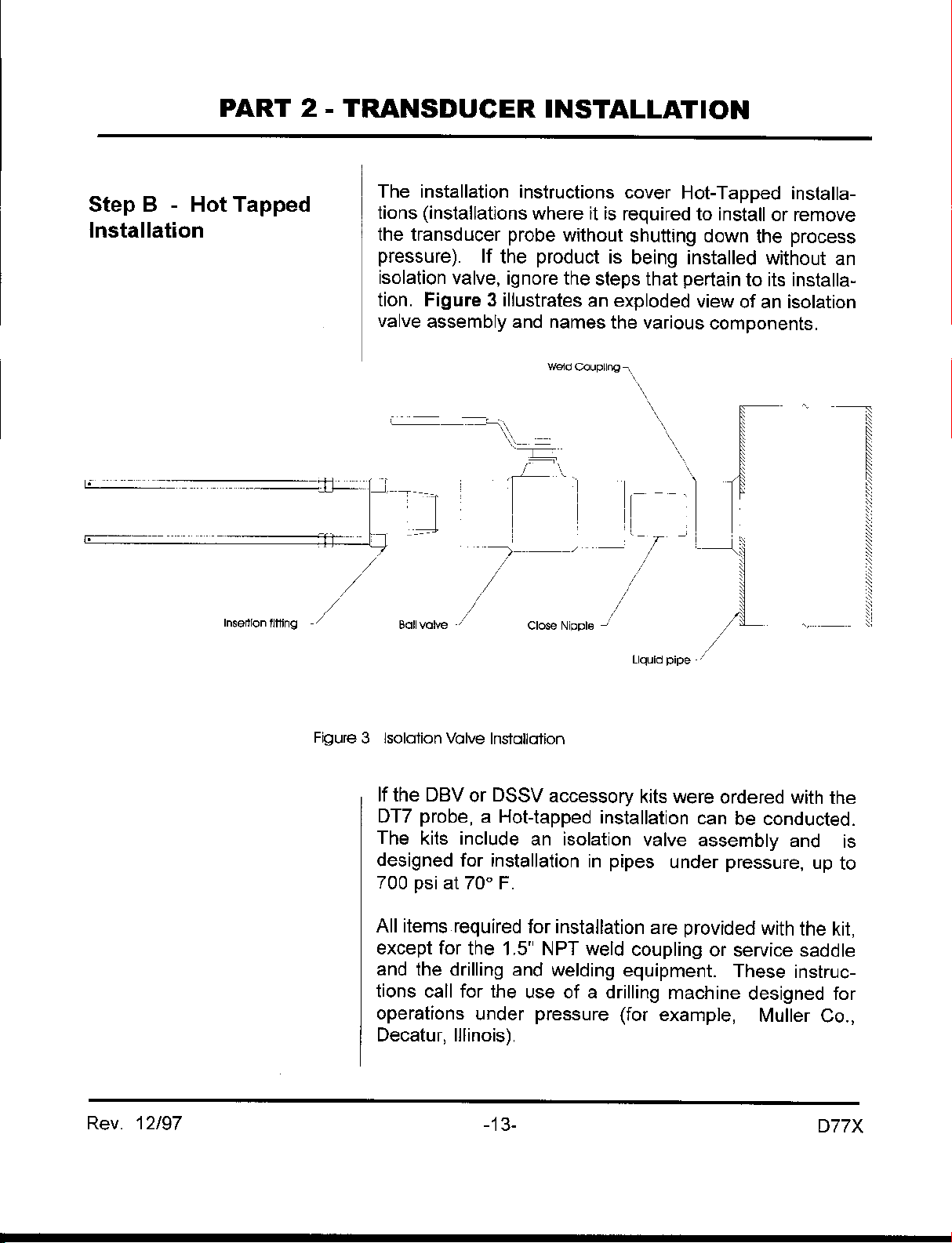
QUICK-START OPE R ATING INSTRUCTIONS
This manual contains detailed operating instructions for
all aspects of the D77X instrument. The following
condensed instructions are provided to assist the
operator in getting the instrument started up and running
as quickly as possible. This pertains to basic operation
only. If specific instrument features are to be used or if
the installer is unfamiliar with this type of instrument,
refer to the appropriate section in the manual for
complete details.
1. TRANSDUCER LOCATION AND PIPE
PREPARATION
A. Select an appropriate mounting location for the
DT7 transducer probe.
B. The probe should be located on a straight piece of
pipe with a minimum of 10 unobstructed pipe
diameters upstream from the installation point and
a minimum of 5 unobstructed diameters
downstream of the installation point.
Pipe Preparation
and Mounting
C. A 1-1/2” NPT female threaded connection on the
pipe is required for the probe assembly to be
mounted. This connection is typically made by
welding a threaded coupling to the pipe wall or
installing a pipe saddle. The connection should
be mounted perpendicular to the pipe at a radial
location 20-160 degrees from the top of the pipe.
2. TRANSDUCER INSTALLATION
DO NOT remove the cotter pins located at the ends
of the threaded rods. They prevent the probe from
being completely extracted from the insertion fitting
and causing a potentially dangerous condition.
A. Insert the DT7 Transducer Probe tip to the 1/8
pipe I.D. location. The velocity measurement is
made 0.67 inches [17 mm] from the very tip of the
probe. Total insertion depth can be calculated at:
Rev. 12/97 -1- D77X
Page 3

QUICK-START OPE R ATING INSTRUCTIONS
Insertion Depth =
(pipe I.D. inches) X 0.125 + 0.67 inches
or
(pipe I.D. mm) X 0.125 + 17 mm
B. Secure the probe insertion distance using the upper
and lower brass jam nuts located on the threaded
rods.
C. Loosen the set screw located in the probe retaining
collar with the enclosed allen wrench.
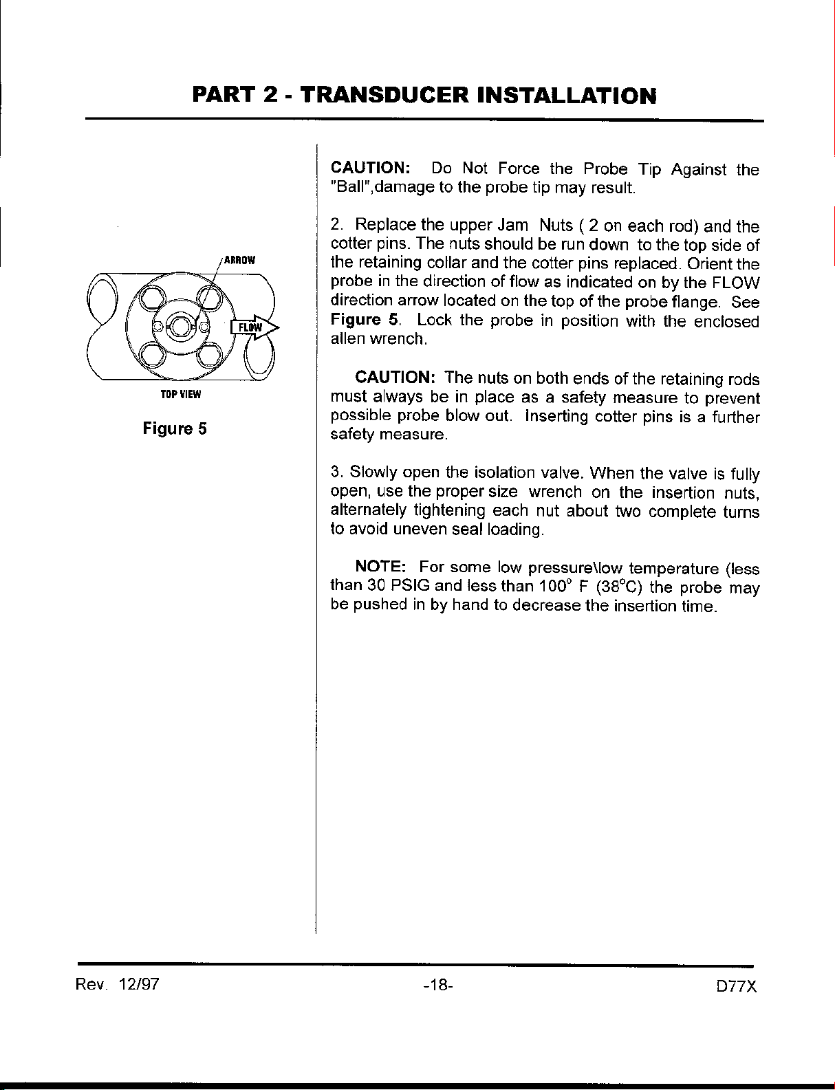
D. Rotate the probe body till the arrowhead, located
on the top of the probe, is parallel with the pipe and
points down stream in the direction of flow.
E. Lock the probe rotation with the set screw in the
retaining collar.
F. Route the transducer cable back to the transmitter,
avoiding locations near high voltage supply wires.
Transducer connections are made through the left
conduit hole in the bottom of the transmitter.
Connections
Startup
3. TRANSDUCER CONNECTION
A. DO NOT attempt to connect additional cable to the
factory supplied transducers.
B. Connect the transducer spade terminals to the
XDCR terminal block located on the lower left
corner of the main PCB.
4. INITIAL SETTINGS AND POWER UP
A. Route a stable, grounded power supply to the
transmitter. Power wiring is made through the right
conduit hole.
B. Connect Power to the upper right terminal block as
appropriate. Apply power.
C. If the D77 system is installed in a pipe full of flowing
liquid, the LED indicator D21 will begin to flash
steadily. If it does not, adjust R10 (GAIN) CW until
the LED just begins to flash.
Rev. 12/97 -2- D77X
Page 4
Page 5
Page 6
Page 7
Page 8
Page 9
Page 10
Page 11
Page 12
Page 13
Page 14

Page 15

Page 16
Page 17
Page 18

Page 19

PART 3 - TRANSMITTER INSTALLATION
Installation of
Transmitter Box
The enclosure should be mounted in an area that is
convenient for servicing, calibration or for observation
of the LCD readout.
1. Locate the transmitter within the length of
transducer cable that was supplied with the D7700
system. If this is not possible, do not attempt to
add additional cable to the transducer. Contact
the Dynasonics factory to coordinate an exchange
for the proper cable length. Transducer cables
that are up to 300 feet [90 meters] are available.
2. Mount the D7700 transmitter in a location that is:
♦ Where little vibration exist.
♦ Protected from falling corrosive fluids.
♦ Within ambient temperature limits - 22 to 122°F
[30 to 50°C]
♦ Out of direct sunlight. Direct sunlight may
increase temperatures within the transmitter to
above maximum limit.
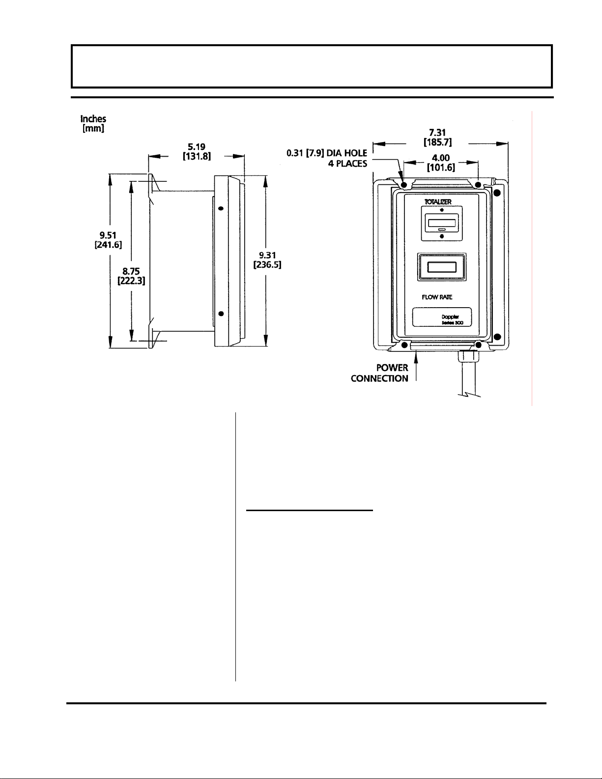
3. Mounting: Refer to Figure 3.1 for enclosure and
mounting dimension details. Ensure that enough
room is available to allow for door swing,
maintenance and conduit entrances. Secure the
enclosure to a flat surface with four appropriate
fasteners.
4. Conduit holes. Conduit hubs should be used
where cables enter the enclosure. Holes not used
for cable entry should be sealed with plugs.
NOTE: Use NEMA 4 [ IP65 ] rated fittings plugs to
maintain the water tight integrity of the enclosure.
Generally, the left conduit hole (viewed from front) is
used for line power; the right conduit hole for
transducer connections.
Rev. 2/00 -3.1- 77X
Page 20
PART 3 - TRANSMITTER INSTALLATION
Figure 3.1
5. If additional holes are required, (analog outputs,
etc.) drill the appropriate size hole in the
enclosure’s bottom. Use extreme care not to run
the drill bit into the wiring or circuits cards.
Electrical Connections
1. To access terminal strips for electronic
connections, loosen the two screws in the
enclosure door and open the door.
2. Guide the transducer terminations through the
transmitter conduit hole located on the right side
of the enclosure. Secure the transducer cable
with the supplied conduit nut.
3. The terminals on the transducer cable are coded
with wire markings. Connect the appropriate wires
to the corresponding screw terminals in the
Rev. 2/00 -3.2- 77X
Page 21

PART 3 - TRANSMITTER INSTALLATION
transmitter. See the electrical connections detail in
Figure 3.2 and 3.3.
NOTE: The transducer cable carries low level
signals. Do not attempt to add additional cable to the
factory supplied transducer cable. If additional cable
is required, contact the Dynasonics factory to arrange
for an exchange transducer with the appropriate
length of cable. Cables to 300 feet [ 90 meters ] are
available.
Rev. 2/00 -3.3- 77X
Page 22
power sources, 24 Vdc of isolated power
is available at the 4-20mA+ terminal. Sim-
ply connecting the target’s (chart recorder,
data logger, ADC) 4-20mA+ and 4-20mA–
inputs to these two output terminals will
drive 4-20mA through 1000 ohms.
utilized to power the 4-20mA loop, Con-
nect the ISOGND terminal to the target’s
ground and the target’s 4-20mA input to
the 4-20mA– terminal.
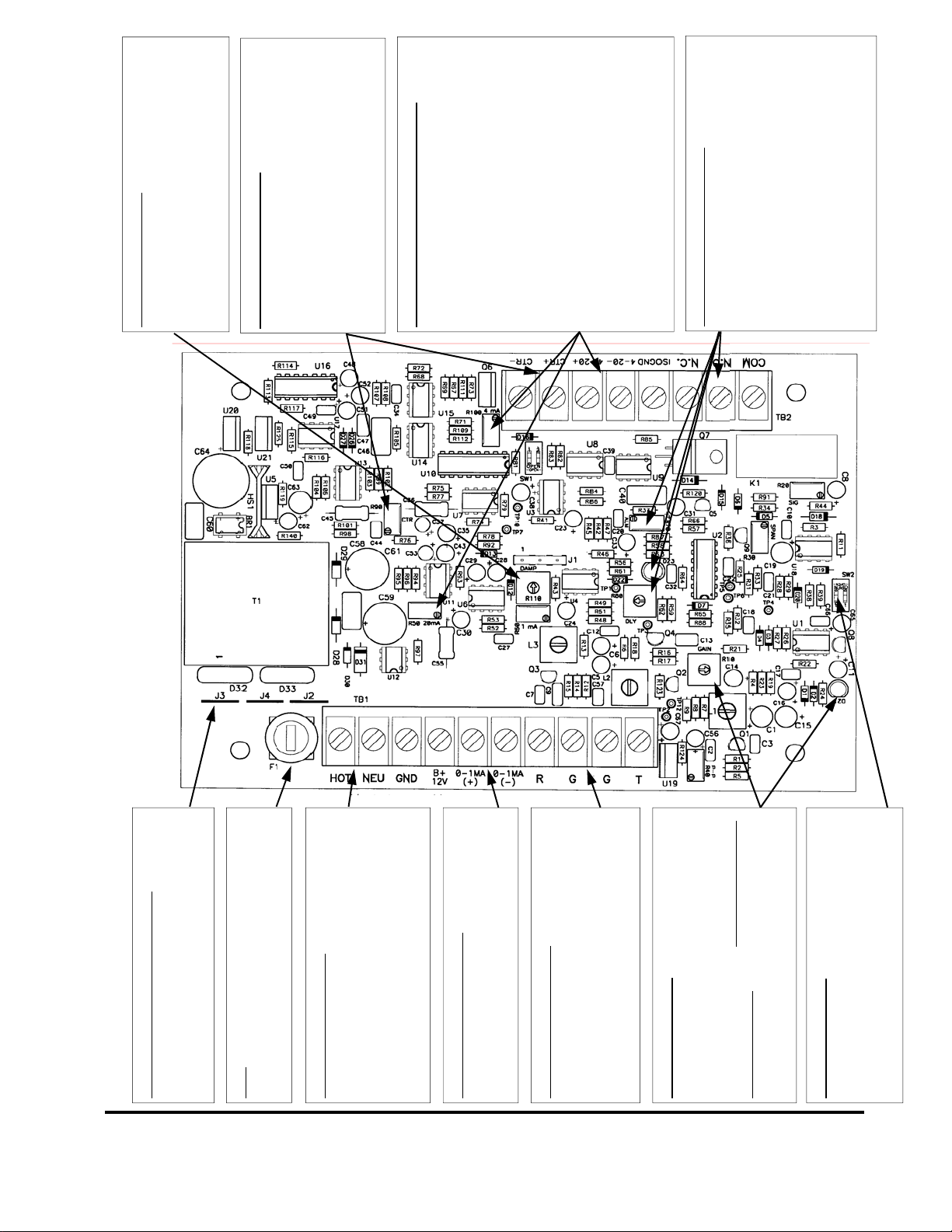
The D300/D301 is equipped with a flow rate
control relay. The relay is designed to control
loads to 250 Vac and 10A. The relay activates
when the flow rate is less than the set point.
Activation is indicated by D23 [LED]. The relay
setpoint is controlled by adjusting R70 [ALM]
there is also a alarm delay feature that requires
the alarm condition to be present for a period of
time before relay activation. The delay can be
Adjust R110 [DAMP] to stabilize flow rate and
R110 [DAMP] Control
output readings. Adjust CCW to increase the
response of the instrument; adjust CW to de-
crease response time (smooth the display
readings and outputs).
CTR Output Connections
The CTR output is designed to operate both
electronic and electromechanical totalizers.
The output can drive loads as low as 90
There are two methods to connect this output:
ohms. Control R90 [CTR] adjusts the span of
this output. Switch set SW1 controls the CTR
output by factors of X10. See details in the
manual describing CTR adjustment.
Isolated 4-20mA Output Connections
• When the D300/D301 is powered from AC
• If the target’s internal DC power source is
Control R100 [4mA] is used to adjust 4mA
offset and R50 [20mA] to adjust 20mA span.
Flow Rate Relay Connections
increased by adjusting R80 [DELAY] CW.
115/230 Vac 50/60 Hz clean AC power re-
quired. Do not connect in parallel with circuits
operating florescent lighting, valves, control
relays, VFDs, etc. GND connection is op-
tional. If GND is connected, verify that it is at
Figure 2.2 D7700 Operated with 115/230 VAC Power Supply 02/02/2000
Power Supply Jumper Placement
115 Vac J2 and J3 only
230 Vac J4 only
12-24 Vdc Does not matter
Fuse
115/230 Vac 1/16A 3AG
Delay Action
AC Power Connections
the same potential as the piping system.
This output is designed to drive loads up to
0-1 mA Output Connection
1500 ohms. Use R60 [1mA] control to adjust
span.
Transducer Connections
Connect the four wires from the two coaxial
cables to the respective terminals. Wire
markers on the coaxial cables identify the “R”
and the “T” pair. Do not run these cables
R10 [GAIN] Control
adjacent to AC power cables.
After all electrical and transducer connections
have been made, the GAIN control is set to
of a flowing liquid. Start with the control fully
match liquid and pipe parameters. To prop-
CCW [counter clockwise]. Adjust CW until
erly set the R10 [GAIN], the pipe must be full
Rev. 2/00 -3.4- 77X
D21 [the LED] just begins to flash steadily.
For measuring fluid velocities up to 20 FPS [6
MPS] set the two switches at SW2 to OPEN.
LOW Velocity Filter
If continuous flow rate will not exceed 2 FPS
[0.6 MPS] turn the two switches ON.
Page 23
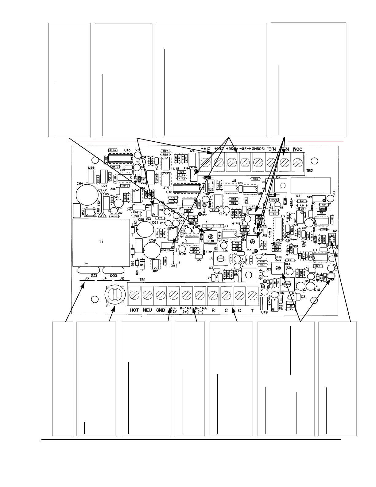
same DC supply operating the flow meter,
connect jumper wires from +B/12V to 4-
20+ and from GND to ISOGND. Connect
the 4-20mA loop load between 4-20+ and
4-20-.
etc.) internal DC power source is utilized
to power the 4-20mA loop, Connect the
ISOGND terminal to the target’s ground,
the target’s +DC output to 4-20+ terminal
and the target’s 4-20mA input to the 4-
20mA– terminal.
Flow Rate Relay Connections
The D300/D301 is equipped with a flow rate
control relay. The relay is designed to control
loads to 250 Vac and 10A. The relay activates
when the flow rate is less than the set point.
Activation is indicated by D23 [LED]. The relay
setpoint is controlled by adjusting R70 [ALM]
there is also a alarm delay feature that requires
the alarm condition to be present for a period
of time before relay activation. The delay can
R110 [DAMP] Control
Adjust R110 [DAMP] to stabilize flow rate
and output readings. Adjust CCW to in-
crease the response of the instrument; adjust
CW to decrease response time (smooth the
display readings and outputs).
CTR Output Connections
The CTR output is designed to operate both
electronic and electromechanical totalizers.
The output can drive loads as low as 90
ohms. Control R90 [CTR] adjusts the span
of this output. Switch set SW1 controls the
CTR output by factors of X10. See details in
Isolated 4-20mA Output Connections
There are two methods to connect this output:
the manual describing CTR adjustment.
• To operate the 4-20mA loop from the
• If the target’s (chart recorder, datalogger,
Control R100 [4mA] is used to adjust 4mA
offset and R50 [20mA] to adjust 20mA span.
be increased by adjusting R80 [DELAY] CW.
Figure 2.3 D7700 Operated with 12-24 Vdc Power Supply 02/02/2000
Power Supply Jumper Placement
12-24 Vdc Does not matter
The fuse provides protection for AC powered
units only. DC power sources should be
connected with a 0.25A current limiter [fuse]
Fuse
in the positive supply line.
12-24 Vdc Power Connections
Connect a DC power source capable of sourc-
ing 0.2A to the terminals marked +B/12V and
GND. The DC power source will operate all
functions of the D300/D301 except the iso-
lated 4-20mA output. See the box describing
Isolated 4-20mA Output for connection details.
This output is designed to drive loads up to
0-1 mA Output Connection
1500 ohms. Use R60 [1mA] control to adjust
span.
Transducer Connections
Connect the four wires from the two coaxial
cables to the respective terminals. Wire
markers on the coaxial cables identify the “R”
and the “T” pair. Do not run these cables
adjacent to AC power cables.
R10 [GAIN] Control
After all electrical and transducer connections
have been made, the GAIN control is set to
CCW [counter clockwise]. Adjust CW until
of a flowing liquid. Start with the control fully
match liquid and pipe parameters. To prop-
erly set the R10 [GAIN], the pipe must be full
Rev. 2/00 -3.5- 77X
For measuring fluid velocities up to 20 FPS [6
MPS] set the two switches at SW2 to OPEN.
If continuous flow rate will not exceed 2 FPS
D21 [the LED] just begins to flash steadily.
LOW Velocity Filter
[0.6 MPS] turn the two switches ON.
Page 24
PART 4 - CONFIGURATION AND OPERATION
Power Up and GAIN
Adjustment
After power has been applied to the flowmeter and if
the pipe is full of a flowing liquid, the LED located on
the bottom of the main circuit card [D21] should begin
flashing. If the LED does not flash, gradually turn the
GAIN control [R10] clockwise until the LED just
begins to flash steadily. (Do not over adjust this
setting as ambient noise can influence readings.)
If possible, turn off the flow to the pipe. Verify that the
LED [D21] ceases to flash. If the LED continues to
flash when flow rate is zero, the GAIN control [R10] is
set too far clockwise and ambient noise is influencing
the readings. Turn the control counter-clockwise until
the flashing ceases. The indicated flow will take
several seconds to achieve the desired reading
because of the built-in electronic damping circuits.
The flow rate meter is factory calibrated to the pipe
size and flow range indicated on the label located on
the inside front cover of the flow meter.
Totalizer - Series D7701 only
Each digit will be in a volumetric unit x 10, x 100, x
1000 or x10,000 as set by SW 1. The totalizer
multiplier that was set at the factory will be indicated
on the label adjacent to the totalizer display. By
changing this switch setting, the totalizer label,
located by the totalizer indicator on the front cover of
the flow meter, will need to be adjusted accordingly.
SW 1—Totalizer Multiplier
SW1-1 SW1-2 MULTIPLIER
OFF OFF X 10
ON OFF X 100
OFF ON X 1000
ON ON X 10000
Rev. 2/00 -4.1- 77X
Page 25

PART 4 - CONFIGURATION AND OPERATION
FIELD CALIBRATION PROCEDURES
After the Equipment is properly installed and
operating, there may be a need to field calibrate the
flowmeter. This could be caused by a number of
reasons:
1. Using a size pipe other than the one specified
when factory configured.
2. When used to measure a liquid with a sound
speed that is different than the one specified when
factory configured.
3. When proper lengths of straight pipe are not
available.
4. Percent of solids are greater than 2%.
5. Operating off turbulence or non-linear suspended
solids.
Field Calibration
Procedure
Field Calibration is as follows:
A. To calibrate the flow rate indicators (meter)
against a known flow:
1. With an established flow, the digital readout and/
or current outputs on D7700 can be adjusted in
accordance with a verified flow measurement, by
adjusting pot R30 (SPAN) adjustment. Turning
the pot C.C.W. decreases the reading. This is a
20 turn, stop-less potentiometer. (Note: Pot R60
will adjust the 0-1 mA output only).
2. It is desired to adjust 4-20 mA to other than
factory calibration, pot R50 can be used to adjust
the 20 mA span.
3. Adjust damping pot R110 for desired flow
response. CW rotation increases flow damping.
The total flow damping range can be varied from
about 5 seconds to 50 seconds. This setting is
usually used to smooth out chart recorder
readings.
Rev. 2/00 -4.2- 77X
Page 26

PART 4 - CONFIGURATION AND OPERATION
B. Totalizer Calibration — Series D7701
1. If an oscilloscope or signal counter is available, a
signal from test point TP10 will show the totalizer
count rate at a particular flow. Refer to the drawing in
the Appendix titled 091-1048-102 Series 300
Waveforms. The pulse rate at TP10 can be x 10, x
100, x 1000 or x10,000 of totalizer count rate, at the
CTR output on terminal strip. For example, if the
pulse rate is 200 milliseconds (multiplier switch SW 1
programmed for 100), then the counter rate at CTR
terminals will be scaled to provide a count every 20
seconds. The total counter output (CTR) range can
be adjusted from approximately 0.5 to 5 seconds with
a full scale flow indication.
Totalizer Adjustment:
(CTR CAL) - (pot R90 and DIP SW 1). The multiplier
DIP switch SW 1 may be programmed as follows:
SW 1 Position
SW1-1 SW1-2 MULTIPLIER
OFF OFF X 10
ON OFF X 100
OFF ON X 1000
ON ON X 10000
If an oscilloscope or signal counter is not available,
then use the following procedure. The Pot R90 has a
range of 0.5 to 5 seconds. SW1 is then used to
increase this rate all the way up to 50 minutes.
2. Stopwatch Procedure - with a known flow rate
established on the flow meter digital display, time the
count rate on the totalizer by a stopwatch, measuring
the time between totalizer counts. If the totalizer is
reading lower than desired, turn CTR, CAL pot R90
Rev. 2/00 -4.3- 77X
Page 27

PART 4 - CONFIGURATION AND OPERATION
C.W. Time the new rate and adjust as required. For
example, if the flow indicator reads 1,000 GPM and a
totalizer count rate of 1 count every 60 seconds
should be displayed. If the actual count rate is one
count every 50 seconds, then turn the adjustment
R90 slightly (with SW 1 Position x 1,000) C.C.W. to
decrease the count rate until there is one count on
the totalizer every 60 seconds when the flow rate
indicator is reading 1,000 GPM. As noted above, 20
full turns on R90 will produce a variation in count rate
of at least x 10, or from approximately 50 to 500
seconds when the indicator is reading full scale. To
determine count rate:
60 (TM)
Count rate = ---------------- GPM
Where,
TM = totalizer multiplier or gallons x totalizer counts
GPM = flow at time of calibration
Electronic Calibration
The flowmeter is electronically calibrated at the
factory by calculating the fluid velocity in Feet per
Second (FPS) that corresponds to the pipe size and
volumetric flow rate that was customer supplied at the
time of the order. The following equations were used
to determine the “calibration frequency” that is
required to properly span the flow meter.
FPS = GPM
(PIPE I.D.)2 X 2.45
Where
PIPE I.D. is inches
A DP7 transducer generates 120 Hz / 1 FPS of
frequency shift when operated on room temperature
water. Alternate fluids can influence this factor. See
Rev. 2/00 -4.4- 77X
Page 28

PART 4 - CONFIGURATION AND OPERATION
the Fluid Sound Speed Compensation chart located
in the Appendix of this manual.
Once a new calibration frequency has been
determined, the frequency is input as a 1 Vpp sinewave into TP3 on the main circuit card. This input will
simulate full scale flow in the circuit. With the function
generator inputting the calibration frequency the
SPAN, 1mA, 20mA and CTR inputs can be
configured. A 10% and 50% of SPAN frequency can
be input and flow meter linearity can be verified.
Noise and Gain Adjust
If meter indicates a reading with no flow, turn R10
(GAIN) C.C.W. just enough to eliminate. Since this
reduces sensitivity, do not turn past point of proper
operation. If indicator will not read flow, turn R10
(GAIN) C.W.
Relay Adjustment
1. Turn R80 (DLY) fully CCW for minimum delay (2
sec.) before proceeding with alarm trip
adjustments.
2. For a point of reference, turn R70 (ALM) also fully
CCW.
3. At the desired flow dropout (which can be
simulated by the procedure covered in the
Electronic Calibration Procedure on Page 4.4),
slowly (due to time delay) adjust alarm R70 (ALM)
CW until relay is deactivated. Do not overturn.
NOTE: About 10% flow hysteresis is built-in into
the flow switch system at 1 FPS.
4. After a desired alarm trip point is established,
adjust R80 (DLY) CW for a desired time delay (20
sec. Max. On flow dropouts).
Rev. 2/00 -4.5- 77X
Page 29

PART 4 - CONFIGURATION AND OPERATION
HOW TO CALIBRATE FOR A DIFFERENT SCALE
& PIPE
This procedure is an outline of how to re-scale the
series D7700 flow meter.
1. The first step is to determine the full scale velocity
setting. To determine this you would need the full
scale setting (i.e. GPM, MGD etc) and the pipe inside
diameter (refer to the charts in the Appendix).
Example calculation: Full scale 500 GPM. Pipe size:
4.026 inches I.D.
Feet per Second = 500 GPM
(4.026)2 x 2.45
2. Multiply the Full Scale in FPS by 120 Hertz.
12.755 * 120 = 1530 Hertz.
3. As described in the Electronic Calibration section
on page 4.4 of this operations manual, input a 1Vpp
sine-wave at 1530 Hz into TP3 to simulate full scale
flow.
4. Adjust R30 (SPAN) for 5.0 VDC at TP7. On A
D301 meter adjust the digital indicator located on the
door of the instrument. The adjustments for the
scaling on the digital indicator are also labeled SPAN.
The fine adjustment on the digital indicator is labeled
CAL. Use both of these adjustments to correctly set
the indicator.
5. On a D301 equipped with a totalizer the new count
rate would be determined by the following example:
60/500 = 0.12 sec per count. In this example it has
been determined that 1 count at .12 sec per count is
equal to 1 gallon. Since 0.12 seconds is too fast for
the electronic circuit design (i.e. 0.5 sec minimum
setting), the decimal place is moved over one and
= 12.755 FPS
Rev. 2/00 -4.6- 77X
Page 30

PART 4 - CONFIGURATION AND OPERATION
the new count rate is 1.2 seconds per count at 10
gallons per count.
A digital counter is placed on the output of the circuit
card to measure the period between pulses so that at
a full scale of 500 GPM the CTR adjustment is set to
correspond to a 1.2 second period interval. The SW1
switch is only used if the customer wishes to set the
gallons per count rate higher (i.e. x 10, x 100, x
1000).
Rev. 2/00 -4.7- 77X
Page 31

A P P E N D I X
Page 32

Fluid Sound Speeds
g
Original Date: 10/19/99
Revision: none
Revision Date: none
File: I:/dynasonics/dyna_code/tables/doppler ss conversions.xls
120.0176921
Doppler
Fluid Specific Gravity Sound Speed Calibration Entry
20 de
Acetate, Butyl (n) 1270 4163.9 85
Acetate, Ethyl 0.901 1085 3559.7 72
Acetate, Methyl 0.934 1211 3973.1 81
Acetate, Propyl 1280 4196.7 85
Acetone 0.79 1174 3851.7 78
Alcohol 0.79 1207 3960.0 81
Alcohol, Butyl (n) 0.83 1270 4163.9 85
Alcohol, Ethyl 0.83 1180 3868.9 79
Alcohol, Methyl 0.791 1120 3672.1 75
Alcohol, Propyl (I) 1170 3836.1 78
Alcohol, Propyl (n) 0.78 1222 4009.2 82
Ammonia (35) 0.77 1729 5672.6 115
Anlline (41) 1.02 1639 5377.3 109
Benzene (29,40,41) 0.88 1306 4284.8 87
Benzol, Ethyl 0.867 1338 4389.8 89
Bromine (21) 2.93 889 2916.7 59
n-Butane (2) 0.60 1085 3559.7 72
Butyrate, Ethyl 1170 3836.1 78
Carbon dioxide (26) 1.10 839 2752.6 56
Carbon tetrachloride 1.60 926 3038.1 62
Chloro-benezene 1.11 1273 4176.5 85
Chloroform (47) 1.49 979 3211.9 65
Diethyl ether 0.71 985 3231.6 66
Diethyl Ketone 1310 4295.1 87
Diethylene glycol 1.12 1586 5203.4 106
Ethanol 0.79 1207 3960.0 81
Ethyl alcohol 0.79 1207 3960.0 81
Ether 0.71 985 3231.6 66
Ethyl ether 0.71 985 3231.6 66
Ethylene glycol 1.11 1658 5439.6 111
Freon R12 774.2 2540 52
Gasoline 0.7 1250 4098.4 83
Glycerin 1.26 1904 6246.7 127
Glycol 1.11 1658 5439.6 111
Isobutanol 0.81 1212 3976.4 81
Iso-Butane 1219.8 4002 81
Isopentane (36) 0.62 980 3215.2 65
Isopropanol (46) 0.79 1170 3838.6 78
Isopropyl alcohol (46) 0.79 1170 3838.6 78
Kerosene 0.81 1324 4343.8 88
Linalool 1400 4590.2 93
rees C m/s ft/s relative to 25C water
Page 33

Linseed Oil .925-.939 1770 5803.3 118
(
)
Methanol (40,41) 0.79 1076 3530.2 72
Methyl alcohol (40,44) 0.79 1076 3530.2 72
Methylene chloride (3) 1.33 1070 3510.5 71
Methylethyl Ketone 1210 3967.2 81
Motor Oil (SAE 20/30) .88-.935 1487 4875.4 99
Octane (23) 0.70 1172 3845.1 78
Oil, Castor 0.97 1477 4845.8 99
Oil, Diesel 0.80 1250 4101 83
Oil (Lubricating X200) 1530 5019.9 102
Oil (Olive) 0.91 1431 4694.9 96
Oil (Peanut) 0.94 1458 4783.5 97
Paraffin Oil 1420 4655.7 95
Pentane 0.626 1020 3346.5 68
Petroleum 0.876 1290 4229.5 86
1-Propanol (46) 0.78 1222 4009.2 82
Refrigerant 11 (3,4) 1.49 828.3 2717.5 55
Refrigerant 12 (3) 1.52 774.1 2539.7 52
Refrigerant 14 (14) 1.75 875.24 2871.5 58
Refrigerant 21 (3) 1.43 891 2923.2 59
Refrigerant 22 (3) 1.49 893.9 2932.7 60
Refrigerant 113 (3) 1.56 783.7 2571.2 52
Refrigerant 114 (3) 1.46 665.3 2182.7 44
Refrigerant 115 (3) 656.4 2153.5 44
Refrigerant C318 (3) 1.62 574 1883.2 38
Silicone (30 cp) 0.99 990 3248 66
Toluene (16,52) 0.87 1328 4357 89
Transformer Oil 1390 4557.4 93
Trichlorethylene 1050 3442.6 70
1,1,1-Trichloro-ethane 1.33 985 3231.6 66
Turpentine 0.88 1255 4117.5 84
Water, distilled
Water 0 degrees C 1402 4596.7 94
Water 20 degrees C 1482 4859.0 99
Water 40 degrees C 1529 5013.1 102
Water 60 degrees C 1551 5085.2 103
Water 80 degrees C 1554 5095.1 104
Water 100 degrees C 1543 5059.0 103
Water 120 degrees C 1519 4980.3 101
Water 140 degrees C 1485 4868.9 99
Water 160 degrees C 1440 4721.3 96
Water 180 degrees C 1390 4557.4 93
Water 200 degrees C 1333 4370.5 89
Water, heavy 1 1400 4593 93
Water, sea 1.025 1531 5023 102
Wood Alcohol (40,41) 0.791 1076 3530.2 72
m-Xylene (46) 0.868 1343 4406.2 90
o-Xylene (29,46) 0.897 1331.5 4368.4 89
p-Xylene (46) 1334 4376.8 89
49,50
0.996 1498 4914.7 100
Page 34
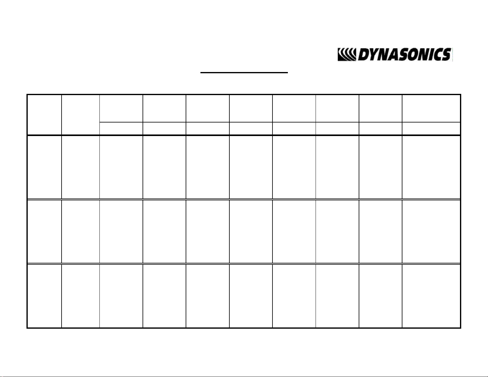
Cement Lining
Ductile Iron Pipe
Standard Classes
Pipe
Size
(inches)
3 3.96 3.46 0.25 3.40 0.28 3.34 0.31 3.28 0.34 3.22 0.37 3.14 0.41
4 4.80 4.28 0.26 4.22 0.29 4.16 0.32 4.10 0.35 4.04 0.38 3.93 0.44
6 6.90 6.40 0.25 6.34 0.28 6.28 0.31 6.22 0.34 6.16 0.37 6.10 0.40 6.04 0.43 .123/.250
8 9.05 8.51 0.27 8.45 0.30 8.39 0.33 8.33 0.36 8.27 0.39 8.21 0.42 8.15 0.45
10 11.10 10.32 0.39 10.46 0.32 10.40 0.35 10.34 0.38 10.28 0.41 10.22 0.44 10.16 0.47
12 13.20 12.58 0.31 12.52 0.34 12.46 0.37 12.40 0.40 12.34 0.43 12.28 0.46 12.22 0.49
14 15.30 14.64 0.33 14.58 0.36 14.52 0.39 14.46 0.42 14.40 0.45 14.34 0.48 14.28 0.51
16 17.40 16.72 0.34 16.66 0.37 16.60 0.40 16.54 0.43 16.48 0.46 16.42 0.49 16.36 0.52
18 19.50 18.80 0.35 18.74 0.38 18.68 0.41 18.62 0.44 18.56 0.47 18.50 0.50 18.44 0.53 .1875/.375
20 21.60 20.88 0.36 20.82 0.39 20.76 0.42 20.70 0.45 20.64 0.48 20.58 0.51 20.52 0.54
24 25.80 25.04 0.38 24.98 0.41 24.92 0.44 24.86 0.47 24.80 0.50 24.74 0.53 24.68 0.56
30 32.00 31.22 0.39 31.14 0.43 31.06 0.47 30.98 0.51 30.90 0.55 30.82 0.59 30.74 0.63
Outside
Diameter
(inches)
Class 53
ID Wall ID Wall ID Wall ID Wall ID Wall ID Wall ID Wall
Class 54 Class 55 Class 56Class 50 Class 51 Class 52
Std./Double
Thickness
36 38.30 37.44 0.43 37.34 0.48 37.06 0.62 37.14 0.58 37.40 0.45 36.94 0.68 36.84 0.73
42 44.50 43.56 0.47 43.44 0.53 43.32 0.59 43.20 0.65 43.08 0.71 42.96 0.77 42.84 0.83 .250/.500
48 50.80 49.78 0.51 49.64 0.58 49.50 0.65 49.36 0.72 49.22 0.79 49.08 0.86 48.94 0.93
54 57.10 55.96 0.57 55.80 0.65 55.64 0.73 55.48 0.81 55.32 0.89 55.16 0.97 55.00 1.05
March, 2000
Page 35

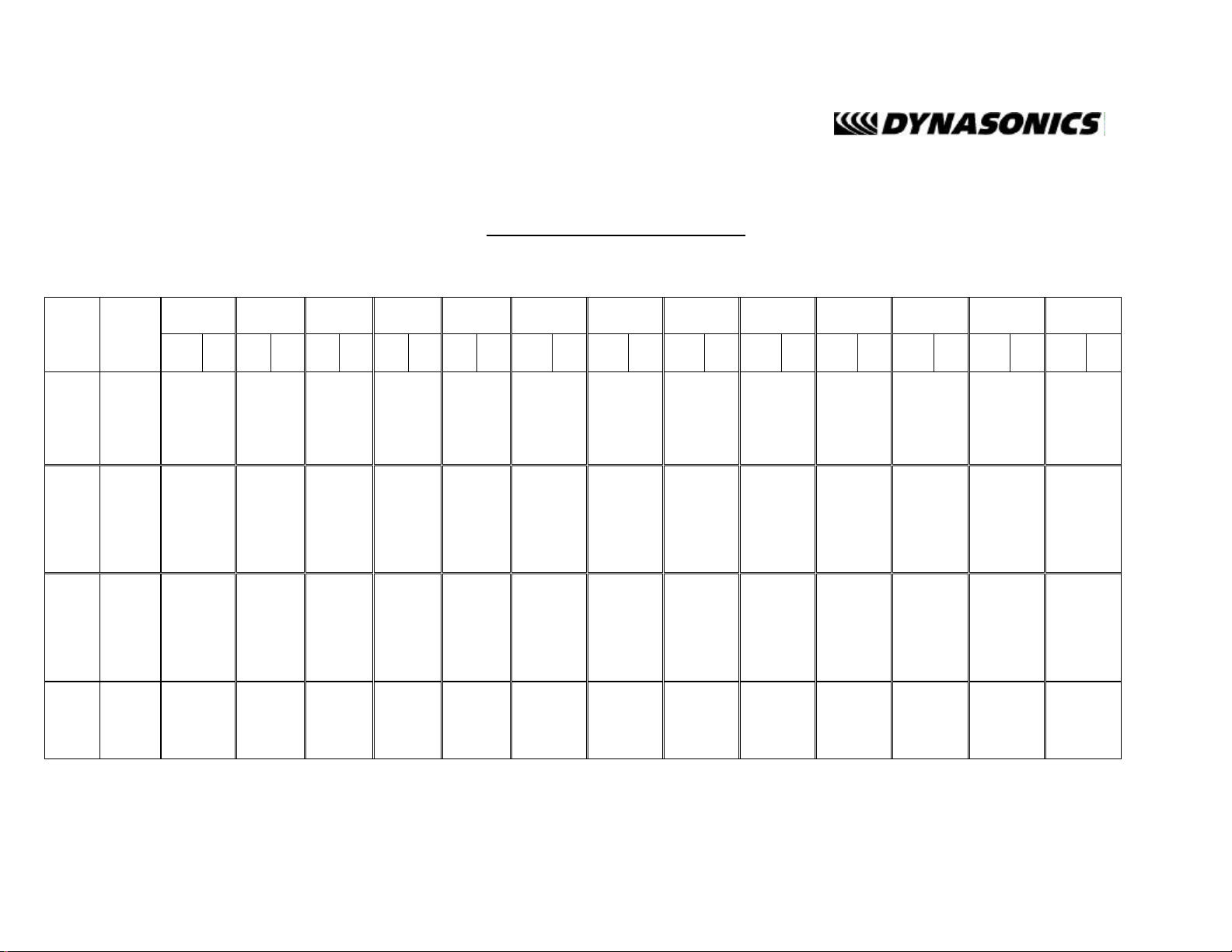
Cast Iron Pipe
Standard Classes
CLASS B CLASS C CLASS D CLASS E CLASS F CLASS G CLASS HCLASS A
Size
(Inches)
10 11.10 10.10 0.50 11.10 9.96 0.57 11.40 10.16 0.62 11.40 10.04 0.68 11.60 10.12 0.74 11.60 10.00 0.80 11.84 10.12 0.86 11.84 10.00 0.92
12 13.20 12.12 0.54 13.20 11.96 0.62 13.50 12.14 0.68 13.50 12.00 0.75 13.78 12.14 0.82 13.78 12.00 0.89 14.08 12.14 0.97 14.08 12.00 1.04
14 15.30 14.16 0.57 15.30 13.98 0.66 15.65 14.17 0.74 15.65 14.01 0.82 15.98 14.18 0.90 15.98 14.00 0.99 16.32 14.18 1.07 16.32 14.00 1.16
16 17.40 16.20 0.60 17.40 16.00 0.70 17.80 16.20 0.80 17.80 16.02 0.89 18.16 16.20 0.98 18.16 16.00 1.08 18.54 16.18 1.18 18.54 16.00 1.27
18 19.50 18.22 0.64 19.50 18.00 0.75 19.92 18.18 0.87 19.92 18.00 0.96 20.34 18.20 1.07 20.34 18.00 1.17 20.78 18.22 1.28 20.78 18.00 1.39
20 21.60 20.26 0.67 21.60 20.00 0.80 22.06 20.22 0.92 22.06 20.00 1.03 22.54 20.24 1.15 22.54 20.00 1.27 23.02 20.24 1.39 23.02 20.00 1.51
24 25.80 24.28 0.76 25.80 24.02 0.89 26.32 24.22 1.05 26.32 24.00 1.16 26.90 24.28 1.31 26.90 24.00 1.45 27.76 24.26 1.75 27.76 24.00 1.88
30 31.74 29.98 0.88 32.00 29.94 1.03 32.40 30.00 1.20 32.74 30.00 1.37 33.10 30.00 1.55 33.46 30.00 1.73
36 37.96 35.98 0.99 38.30 36.00 1.15 38.70 35.98 1.36 39.16 36.00 1.58 39.60 36.00 1.80 40.04 36.00 2.02
42 44.20 42.00 1.10 44.50 41.94 1.28 45.10 42.02 1.54 45.58 42.02 1.78
48 50.50 47.98 1.26 50.80 47.96 1.42 51.40 47.98 1.71 51.98 48.00 1.99
O.D.
Inch
3 3.80 3.02 0.39 3.96 3.12 0.42 3.96 3.06 0.45 3.96 3.00 0.48
4 4.80 3.96 0.42 5.00 4.10 0.45 5.00 4.04 0.48 5.00 3.96 0.52
6 6.90 6.02 0.44 7.10 6.14 0.48 7.10 6.08 0.51 7.10 6.00 0.55 7.22 6.06 0.58 7.22 6.00 0.61 7.38 6.08 0.65 7.38 6.00 0.69
8 9.05 8.13 0.46 9.05 8.03 0.51 9.30 8.18 0.56 9.30 8.10 0.60 9.42 8.10 0.66 9.42 8.10 0.66 9.60 8.10 0.75 9.60 8.00 0.8
I.D.
Inch
Wall
O.D.
Inch
I.D.
Inch
Wall
O.D.
Inch
I.D.
Inch
Wall
O.D.
Inch
I.D.
Inch
Wall
O.D.
Inch
I.D.
Inch
Wall
O.D.
Inch
I.D.
Inch
Wall
O.D.
Inch
I.D.
Inch
Wall
O.D.
Inch
I.D.
Inch
Wall
54 56.66 53.96 1.35 57.10 54.00 1.55 57.80 54.00 1.90 58.40 53.94 2.23
60 62.80 60.02 1.39 63.40 60.06 1.67 64.20 60.20 2.00 64.82 60.06 2.38
72 75.34 72.10 1.62 76.00 72.10 1.95 76.88 72.10 2.39
84 87.54 84.10 1.72 88.54 84.10 2.22
March, 2000
Page 36
Steel, Stainless Steel, P.V.C.
Standard Schedules
Nominal
Pipe Size
Inches
OUTSIDE
DIAMETER
1 1.315 1.185 0.065 1.097 0.109 1.049 1.049 0.133 0.957 0.179 0.957 0.179 0.815 0.250
1.25 1.660 1.530 0.065 1.442 0.109 1.380 1.380 0.140 1.278 0.191 1.278 0.191 1.160 0.250
1.5 1.900 1.770 0.065 1.682 0.109 1.610 1.610 0.145 1.500 0.200 1.500 0.200 1.338 0.281
2 2.375 2.245 0.065 2.157 0.109 2.067 2.067 0.154 1.939 0.218 1.939 0.218 1.687 0.344
2.5 2.875 2.709 0.083 2.635 0.120 2.469 2.469 0.203 2.323 0.276 2.323 0.276 2.125 0.375
3 3.500 3.334 0.083 3.260 0.120 3.068 3.068 0.216 2.900 0.300 2.900 0.300 2.624 0.438
3.5 4.000 3.834 0.083 3.760 0.120 3.548 3.548 0.226 3.364 0.318 3.364 0.318
4 4.500 4.334 0.083 4.260 0.120 4.026 0.237 4.026 0.237 3.826 0.337 3.826 0.337 3.624 0.438 3.624 0.438 3.438 0.531
5 5.563 5.345 0.109 5.295 0.134 5.047 0.258 5.047 0.258 4.813 0.375 4.813 0.375 4.563 0.500 4.563 0.500 4.313 0.625
6 6.625 6.407 0.109 6.357 0.134 6.065 0.280 6.065 0.280 5.761 0.432 5.761 0.432 5.501 0.562 5.501 0.562 5.187 0.719
8 8.625 8.407 0.109 8.329 0.148 8.125 0.250 8.071 0.277 7.981 0.322 7.981 0.322 7.813 0.406 7.625 0.500 7.625 0.500 7.437 0.594 7.187 0.719 7.187 0.719 6.183 1.221
10 10.750 10.482 0.134 10.42 0.165 10.25 0.250 10.13 0.310 10.02 0.365 10.020 0.365 9.750 0.500 9.750 0.500 9.562 0.594 9.312 0.719 9.062 0.844 9.062 0.844 8.500 1.125
12 12.750 12.420 0.165 12.39 0.180 12.25 0.250 12.09 0.330 12.00 0.375 11.938 0.406 11.626 0.562 11.750 0.500 11.370 0.690 11.060 0.845 10.750 1.000 10.750 1.000 10.120 1.315
14 14.000 13.50 0.250 13.37 0.315 13.25 0.375 13.25 0.375 13.124 0.438 12.814 0.593 13.000 0.500 12.500 0.750 12.310 0.845 11.810 1.095 11.810 1.095 11.180 1.410
16 16.000 15.50 0.250 15.37 0.315 15.25 0.375 15.25 0.375 15.000 0.500 14.688 0.656 15.000 0.500 14.310 0.845 13.930 1.035 13.560 1.220 13.560 1.220 12.810 1.595
18 18.000 17.50 0.250 17.37 0.315 17.12 0.440 17.25 0.375 16.876 0.562 16.564 0.718 17.000 0.500 16.120 0.940 15.680 1.160 15.250 1.375 15.250 1.375 14.430 1.785
20 20.000 19.50 0.250 19.25 0.375 19.25 0.375 19.25 0.375 18.814 0.593 18.376 0.812 19.000 0.500 17.930 1.035 17.430 1.285 17.000 1.500 17.000 1.500 16.060 1.970
24 24.000 23.50 0.250 23.25 0.375 23.25 0.375 23.25 0.375 22.626 0.687 22.126 0.937 23.000 0.500 21.560 1.220 20.930 1.535 20.930 1.535 20.930 1.535 19.310 2.345
30 30.000 29.37 0.315 29.00 0.500 29.00 0.500 29.25 0.375 29.250 0.375 29.000 0.500
36 36.000 35.37 0.315 35.00 0.500 35.00 0.500 35.25 0.375 35.250 0.375 35.000 0.500
42 42.000 41.25 0.375 41.250 0.375 41.000 0.500
48 48.000 47.25 0.375 47.250 0.375 47.000 0.500
SCH.
5
ID Wall ID Wall ID Wall ID Wall ID Wall ID Wall ID Wall ID Wall ID Wall ID Wall ID Wall ID Wall ID Wall
SCH. 10
(LTWALL)
SCH. 20 SCH. 30 STD. SCH. 40 SCH. 60 SCH. 140 SCH. 180
X STG. SCH. 80 SCH. 100 SCH. 120
March, 2000
Page 37

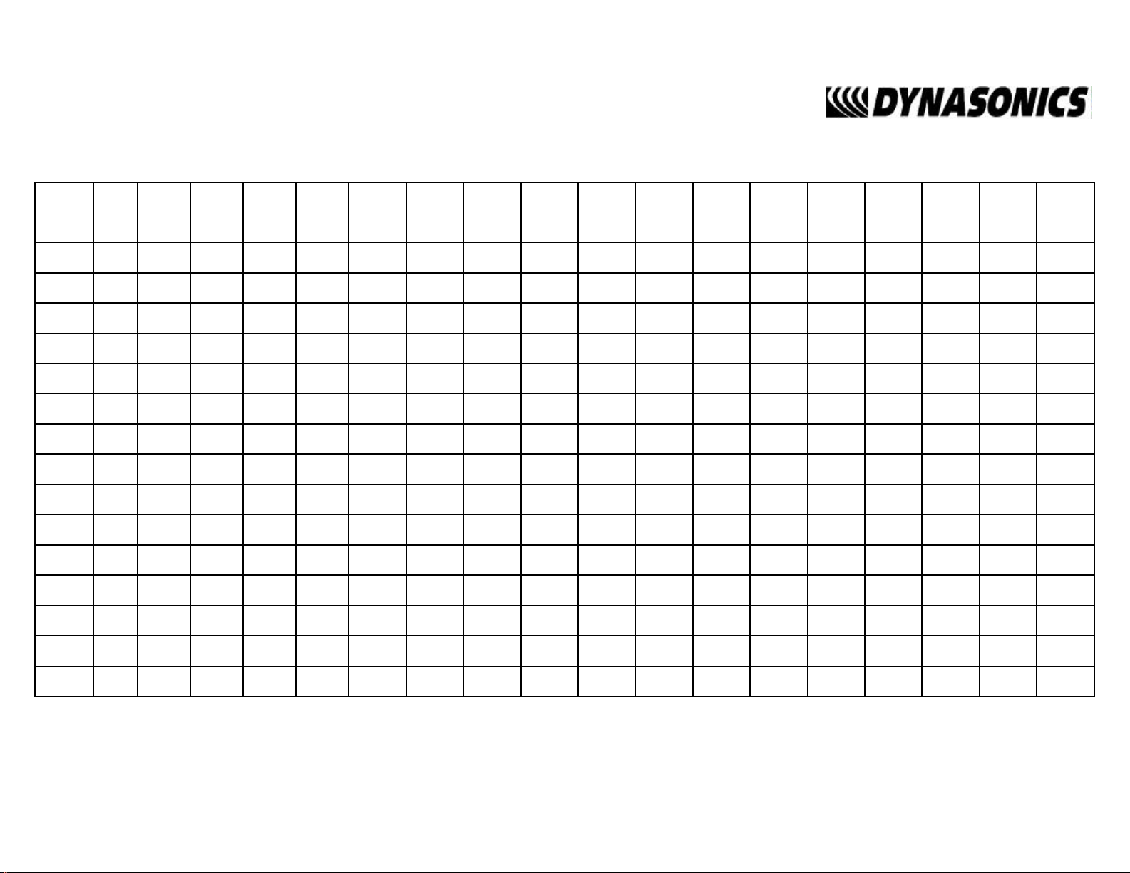
FPS TO GPM CROSS - REFERENCE (Schedule 40)
Nominal
Pipe
(Inches)
1 1.05 2.6989 4.0484 5.3978 6.7473 8.097 9.4462 10.796 12.145 13.490 14.844 16.190 17.540 18.890 20.240 21.590 22.941 24.290
1.25 1.38 4.6620 6.9929 9.3239 11.655 13.99 16.317 18.648 20.979 23.310 25.641 27.970 30.300 32.630 34.960 37.300 39.627 41.958
1.5 1.61 6.3454 9.5182 12.691 15.864 19.04 22.209 25.382 28.555 31.730 34.900 38.070 41.250 44.420 47.590 50.760 53.936 57.109
2 2.07 10.489 15.734 20.979 26.224 31.47 36.713 41.958 47.202 52.450 57.692 62.940 68.180 73.430 78.670 83.920 89.160 94.405
2.5 2.47 14.935 22.402 29.870 37.337 44.80 52.272 59.740 67.207 74.670 82.142 89.610 97.080 104.50 112.00 119.50 126.95 134.41
3 3.07 23.072 34.608 46.144 57.680 69.22 80.752 92.288 103.82 115.40 126.90 138.40 150.00 161.50 173.00 184.60 196.11 207.65
3.5 3.55 30.851 46.276 61.702 77.127 92.55 107.98 123.40 138.83 154.30 169.68 185.10 200.50 216.00 231.40 246.80 262.23 277.66
4 4.03 39.758 59.636 79.515 99.394 119.3 139.15 159.03 178.91 198.80 218.67 238.50 258.40 278.30 298.20 318.10 337.94 357.82
5 5.05 62.430 93.645 124.86 156.07 187.3 218.50 249.72 280.93 312.10 343.36 374.60 405.80 437.00 468.20 499.40 530.65 561.87
6 6.06 89.899 134.85 179.80 224.75 269.7 314.65 359.60 404.55 449.50 494.45 539.40 584.30 629.30 674.20 719.20 764.14 809.09
8 7.98 155.89 233.83 311.78 389.72 467.7 545.61 623.56 701.50 779.40 857.39 935.30 1013.0 1091.0 1169.0 1247.0 1325.1 1403.0
10 10.02 245.78 368.67 491.56 614.45 737.3 860.23 983.12 1106.0 1229.0 1351.8 1475.0 1598.0 1720.0 1843.0 1966.0 2089.1 2212.0
I.D.
INCH
1 1.5 2 2.5 3 3.5 4 4.5 5 5.5 6 6.5 7 7.5 8 8.5 9
12 11.94 348.99 523.49 697.99 872.49 1047.0 1221.5 1396.0 1570.5 1745.0 1919.5 2094.0 2268.0 2443.0 2617.0 2792.0 2966.5 3141.0
14 13.13 422.03 633.04 844.05 1055.1 1266.0 1477.1 1688.1 1899.1 2110.0 2321.1 2532.0 2743.0 2954.0 3165.0 3376.0 3587.2 3798.2
16 15.00 550.80 826.20 1101.6 1377.0 1652.0 1927.8 2203.2 2478.6 2754.0 3029.4 3305.0 3580.0 3856.0 4131.0 4406.0 4681.8 4957.2
FPS TO GPM: GPM = (PIPE ID)² X VELOCITY IN FPS X 2.45 FPS X .3048 = MPS
GPM TO FPS: FPS =
GPM
(ID)² X 2.45
GPM X .0007 = GPD
GPM X 3.7878 = LPM
Page 38
FPS TO GPM CROSS - REFERENCE (Schedule 40)
Nominal
Pipe
(Inches)
18 16.88 697.52 1046.3 1395.0 1743.8 2093.0 2441.3 2790.1 3138.8 3488.0 3836.3 4185.0 4534.0 4883.0 5231.0 5580.0 5928.9 6277.7
20 18.81 866.14 1299.0 1732.0 2165.3 2598.4 3031.5 3464.6 3897.6 4330.7 4763.8 5196.8 5629.9 6063.0 6496.0 6929.1 7362.2 7795.3
24 22.63 1253.7 1880.0 2507.0 3134.1 3761.0 4387.8 5014.6 5641.5 6268.3 6895.1 7522.0 8148.8 8775.6 9402.4 10029 10656 11283
26 25.25 1560.7 2341.0 3121.0 3901.9 4682.2 5462.6 6243.0 7023.4 7803.7 8584.1 9364.5 10145 10925 11706 12486 13266 14047
28 27.25 1817.8 2727.0 3636.0 4544.5 5453.4 6362.3 7271.2 8180.0 9088.9 9997.8 10907 11816 12725 13633 14542 15451 16360
30 29.25 2094.4 3142.0 4189.0 5236.0 6283.2 7330.4 8377.6 9424.9 10472 11519 12566 13614 14661 15708 16755 17803 18850
32 31.25 2390.6 3586.0 4781.0 5976.5 7171.9 8367.2 9562.5 10758 11953 13148 14344 15539 16734 17930 19125 20320 21516
34 33.25 2706.4 4060.0 5413.0 6766.0 8119.2 9472.4 10826 12179 13532 14885 16238 17592 18945 20298 21651 23004 24358
36 35.25 3041.8 4563.0 6084.0 7604.5 9125.4 10646 12167 13688 15209 16730 18251 19772 21292 22813 24334 25855 27376
42 41.25 4165.4 6248.0 8331.0 10414 12496 14579 16662 18744 20827 22910 24992 27075 29158 31241 33323 35406 37489
48 47.99 5637.8 8457.0 11276 14095 16913 19732 22551 25370 28189 31008 33827 36646 39465 42284 45103 47922 50740
54 53.98 7133.1 10700 14266 17833 21399 24966 28532 32099 35665 39232 42798 46365 49931 53498 57065 60631 64198
I.D.
INCH
1 1.5 2 2.5 3 3.5 4 4.5 5 5.5 6 6.5 7 7.5 8 8.5 9
60 60.09 8839.2 13259 17678 22098 26518 30937 35357 39777 44196 48616 53035 57455 61875 66294 70714 75134 79553
72 72.10 12726 19089 25451 31814 38177 44540 50903 57266 63628 69991 76354 82717 89080 95443 101805 108168 114531
84 84.10 17314 25971 34628 43285 51943 60600 69257 77914 86571 95228 103885 112542 121199 129856 138514 147171 155828
FPS TO GPM: GPM = (PIPE ID)² X VELOCITY IN FPS X 2.45 FPS X .3048 = MPS
GPM TO FPS: FPS =
GPM
(ID)² X 2.45
GPM X .0007 = GPD
GPM X 3.7878 = LPM
Page 39

GENERAL TERMS AND CONDITIONS OF SALES
1. PAYMENT – Terms of payment are effective from the actual date of invoice. If, in the Seller’s
opinion, the financial condition of the Buyer at any time – or any other circumstances – do not justify
the incurrence of production costs of shipment on the terms of payment specified, the Seller may
require partial or full payment in advance. Payment terms are net 30 days unless otherwise stated on
invoice.
2. F.O.B. – All shipments are from Racine, Wisconsin, USA, unless otherwise other stated, and title
transfers to the buyer upon leaving factory.
3. QUOTATION AND PRICES – Quoted prices are firm for 30 days unless stated in the quotati on and
are subject to change without notice after expiration of this period.
4. TAXES – Any applicable sales, use, revenue, excise or other taxes not specifically stated in the
quotation are to be remitted by the Buyer directly to the appropriate regulatory agency.
5. WARRANTY – Seller’s standard published warranty in effect at the time of shipment shall apply.
This warranty is exclusive and is in lieu of all other warranties, express, implied, or statutory, including
the warranty of merchantability.
6. DELIVERY – The Seller shall not be liable for loss or damage of any kind resulting from delay or
inability to deliver on account of flood, fire, labor trouble, riots, civil disturbances, accidents, acts or
orders or regulations of civil or military authorities, sh ortages of material, or any other causes beyond
Seller’s control.
7. PRODUCT CHANG ES – In keeping with our continuing policy of product improvement, we reserve
the right to make changes in our products at any time, without incurring an obligation to change,
replace or upgrade equipment previously shipped.
8. CANCELLATIONS – An order placed by Buyer and accepted by Seller may be cancelled only with
the Seller’s consent and upon terms that will indemnify the Seller against loss.
9. RESTOCKING CHARGE – On standard equipment, the charge is 25%, provided the equipment is
returned within 30 days in acceptable condition with a RGA number. Restocking charges for special
equipment may vary from standard equipment, and will be handled on a case-by-case basis. No
returns will be taken after one year.
Page 40

Limited Warranty and Disclaimer
Dynasonics, div. of Racine Federated Inc. warrants to the end purchaser, for a period of
one year from the date of shipment from our factory, that all new transmitters and
transducers manufactured by it are free from defects in materials and workmanship.
This warranty does not cover products that have been damaged due to normal use,
misapplication, abuse, lack of maintenance, or improper installation. Dynasonics’
obligation under this warranty is limited to the repair or replacement of a defective
product, at no charge to the end purchaser, if the product is inspected by Dynasonics
and found to be defective. Repair or replacement is at Dynasonics’ discretion. An
authorization number must be obtained from Dynasonics before any product may be
returned for warranty repair or replacement. The product must be thoroughly cleaned
and any process chemicals removed before it will be accepted for return.
The purchaser must determine the applicability of the product for its desired use and
assumes all risks in connection therewith. Dynasonics assumes no responsibility or
liability for any omissions or errors in connection with the use of its products.
Dynasonics will under no circumstances be liable for any incidental, consequential,
contingent or special damages or loss to any person or property arising out of the failure
of any product, component or accessory.
All expressed or implied warranties, including the implied warranty of
merchantability and the implied warranty of fitness for a particular purpose or
application are expressly disclaimed and shall not apply to any products sold or
services rendered by Dynasonics.
The above warranty supersedes and is in lieu of all other warranties, either expressed or
implied and all other obligations or liabilities. No agent or representative has any
authority to alter the terms of this warranty in any way.
Page 41

RETURN OF EQUIPMENT/SALES INFORMATION
CONTACTS AND PROCEDURES
Customer Service/Application Engineer:
If you have a question regarding order status, placing an order, reviewing applications for
future purchases, or wish to purchase a new flowmeter, please contact our new National
Sales and Marketing Headquarters:
DYNASONICS
Division of Racine Federated, Inc.
8635 Washington Avenue
Racine, WI 53406
PHONE: (800)535-3569 or
(262)639-6770
FAX: (262)639-2267
Service/Repair Department:
If you already purchased equipment and have an operation problem, require service, or
need to schedule field service, please contact our Service Department:
DYNASONICS
Division of Racine Federated, Inc.
8635 Washington Avenue
Racine, WI 53406
PHONE: (800)535-3569 or
(262)639-6770
FAX: (262)639-2267
Return Goods Authorization:
When returning equipment, it is necessary for you to contact our Service Department at
(800)535-3569 or (262)639-6770 to obtain an RGA number for the authority and proper
tracking of your material and its prompt inspection and return. The RGA number should
be noted on the outside of the box. All returns of equipment go to the following address:
DYNASONICS
Division of Racine Federated, Inc.
8635 Washington Avenue
Racine, WI 53406
Attn: RGA #
Page 42

8635 WASHINGTON AVENUE
RACINE, WI 53406
TOLL-FREE IN NORTH AMERICA.:
TEL: (800) 535-3569 FAX: (800) 732-8354
TEL: (262) 639-6770 FAX: (262) 639-2267
URL: www.dynasonics.com
 Loading...