

Page 1

Series
Series D300/301
Series Series
Doppler Ultrasonic Flow Meter
Operations & Maintenance
D300/301
D300/301D300/301
Manual
REV 2/00
Page 2

PART 1 - TABLE OF CONTENTS
Description Pages
Quick Start Installation 1.2-1.3
Operating Theory 1.4
Product Limitations 1.5
Model Number Matrix 1.6
Specifications 1.7
Pre-Installation Bench Test 2.1
Transducer Installation 2.2-2.6
Transmitter Installation 3.1-3.2
Electrical Connections 3.2-3.5
Power Up and Configuration 4.1
Field Calibration 4.2-4.5
Relay Adjustment 4.5
Changing Pipe Size or Flow Span 4.6-4.7
Appendix
Fluid Sound Speed Conversions
Ductile Iron Pipe Data
Cast Iron Pipe Data
Steel, SS, PVC Pipe Data
FPS to GPM Conversion Chart
Intrinsic Safety Installation
Troubleshooting Waveform s Ref.
Statement of Warranty
Service Information
Rev. 2/00 -1.1- 300/301
Page 3

PART 1 - QUICK START
General
This manual contains detailed operating instructions
for all aspects of the D300/301 instrument. The
following condensed instructions are provided to
assist the operator in getting the instrument started
up and running as quickly as possible. Thi s pertains
to basic operation only. If specific instrument features
are to be used or if the installer is unfamiliar with this
type of instrument, refer to the appropriate section i n
the manual for complete details.
1. TRANSDUCER LOCATION
A. In general, select a mounting location on the
piping system with a minimum of 10 pipe
diameters (10 X the pipe inside diameter) of
straight pipe upstream and 5 straight diameters
downsteam. See Table 2.1 for additional
configurations.
B. On horizontal pipe, select a position that is
between 2 and 4 o’clock on the pipe, with 12
o’clock representing the top.
Transducer Cable
FLOW
Figure 1.1
Top View of Pipe
2. PIPE PREPARATION AND TRANSDUCER
MOUNTING
A. The piping surface, where the transducers are
to be mounted, needs to be clean and dry.
Remove loose scale, rust and paint to ensure
satisfactory acoustical bonds.
B. Loosely wrap the appropriate length of strap
around the pipe at the l ocation determined in
Step 1. Refer to Figure 1.1 for proper
orientation.
C. Apply a liberal amount of couplant onto the
transducer face. Pl ace the transducer onto the
pipe ensuring square and true placement. If
an RTV type of couplant (requiring curing
time) was utilized, allow sufficient time for
curing before applying power to the instrument.
Rev. 2/00 -1.2- 300/301
Page 4

PART 1 - QUICK START
3. TRANSDUCER/POWER CONNECTIONS
A. Do not attempt to add additional cable to the
transducers.
B. Refer to the WIRING DIAGRAM in Figure 1.2
for proper power and transducer connections.
Verify proper jumper selections are in place for
the power source. See Figures 2.2 and 2.3.
4. INITIAL SETT INGS AND POWER UP
Power Connections Transducer Connections
IMPORTANT!
In order to successfully complete the configuration of
the D300/301 flow meter, the transducer must be
mounted on a pipe which is full of a flowing liquid. I t
is normal to have zero readings and no si gnal indicator LED with empty pipes or zero flow rate.
Figure 1.2
Power and Transducer
Connections
A. Adjust the GAIN control [R10] to 1/4 turn from
full counter-clockwise rotati on. Set the DAMP
control R110 to 1/2 turn from either stop.
B. Apply power to the instrument.
C. If the pipe is full of a flowing liquid, the LED
located on the bottom of the main circuit card
[D21] should begin flashing. If the LED does
not flash, gradually turn the GAIN control [R10]
clockwise until the LED just begins to flash
steadily. (Do not over adjust this setting as
ambient noise can influence readings.)
D. If possible, turn off the flow to the pipe. Verify
that the LED [D21] ceases to flash. If the LED
continues to flash when flow rate is zero, the
GAIN control [R10] is set too far clockwise and
ambient noise is influencing the readings.
Turn the control counter-clockwise until the
flashing ceases.
E. If the instrument passes steps 4C and 4D, the
basic setup of the instrument is complete.
Rev. 2/00 -1.3- 300/301
Page 5

PART 1 - GENERAL
General
Operating Theory
The Dynasonics D300/301 flowmeter is designed to
measure the flow of liquids and slurries in full-pipe
closed systems. The transmitter is factory configured
to measure flow on a specific, customer specified,
pipe, where flow range and measuring units have
been supplied to the Dynasonics factory during
assembly and factory calibration. The standard
product is typically used on pipe sizes ranging from
1 - 120 inch [ 25 - 1524 mm ] pipe I.D. (With the
small pipe transducer option, the pipe size range is
0.25 - 1 inch [ 6 - 25 mm]). A variety of liquid
applications can be accommodated: sewage,
sludges, concrete, mining slurries, dredging, etc.
Because the transducers are non-contacting and
have no moving parts, the flow meter is not affected
by system pressure, fouling or wear. Standard
transducers are rated to 250°F [121°C]. Optional
high temperature transducers are rated to operate to
400°F [204°C].
The basic principle of operation is the measurement
of the frequency shift “Doppler” of a reflected
ultrasonic signal from discontinuity in the flowing
liquid. In theory, these di scontinuities can be virtuall y
any amount of suspended bubbles, solids, or
interfaces caused by turbulent flow. In practice the
degree to which this can be reliably accomplished is a
function of the sensitivity and frequency of the
transducer and associated transmitter. The
D300/301 design requires greater than 100 PPM of
suspended solids or bubbles over 100 microns in
size. Should your application be cleaner than this,
please check with factory for information on transit
time ultrasonic flowmeters. The transducer which
generates and receives the ultrasoni c signal supplies
the data to the transmitter. The transmitter processes
the signal and provides an analog and pulse output
for velocity indicating and volumetric totalizing. In
addition, the transmitter contains a signal light which
determines satisfactory operation.
Rev. 2/00 -1.4- 300/301
Page 6

PART 1 - GENERAL
Measuring Limits
The flowmeter is typically used as a unidirectional
meter and is most accurate when the transducer is
mounted in the orientation detailed in this manual.
But, the meter will measure flow in both directions —
although flow direction will not be indicated or
totalized properly. The flowmeter will operate from
signals returned from turbulence alone (such as
installation directly at pump discharges or
downstream from elbows and valves); however, it
should be noted that turbulence may vary with flow
rates and result in non-linear results. The
repeatability of the device is not dependent on most
process liquids.
The flowmeter is designed to measure the flow of
liquids and slurries, as long as a small, homogeneous
quantity of entrained air or suspended solids are
present. Without the presence of continuing supply of
air or solids, the transmitted pulses are not reflected
back to the transducer and the indicator will indicate
zero flow. Also, the LED signal indicator will be
extinguished.
The signal strength light will indicate (continuously
blink) when a minimum size and concentration of
suspended particles are available for a reliable flow
reading (100 micron and 100 PPM minimum) and the
liquid is moving at least 0.1 FPS [0.03 MPS]. Most
water-based liquids can be measured from a factory
calibrated flowmeter. However, liquids with a heavy
solids level (i.e. over 2%), liquids with sound speeds
that vary from water (see Appendix of alternate
liquids list) or pipes with liners may have to be field
calibrated. This is done by adjusting the span pot
(R30 on circuit board) to make the indicator agree
with a known flow velocity or a mathematically
corrected fluid velocity. All standard indicator scales
are calibrated to customer specified units. If the scale
range or units need to changed, the process to do so
is covered in detail later in this manual.
Rev. 2/00 -1.5- 300/301
Page 7

Serial Number
PART 1 - GENERAL
The D300/301 employs modular construction and
provides electrical safety for the operator. The
display face contains voltages no greater than 9 Vdc
and the metal work is electrically connected to Earth
Ground. The display face swings open to allow
access to user connections.
The serial number and complete model number of
your D300/301 is located on the inside of the
transmitter’s front cover. Shoul d technical assistance
be required, please provide the Dynasoncs’ Customer
Service Department with this information.
A part number breakdown of the transducer and
transmitter portions of the flowmeter are described
below.
Transmitter Transducer
Rev. 2/00 -1.6- 300/301
Page 8

PART 1 - GENERAL
Rev. 2/00 -1.7- 300/301
Page 9

PART 2 - TRANSDUCER INSTALLATION
Unpacking
Bench Test
Power Connections
After unpacking, it is recommended to save the
shipping carton and packing materials in case the
instrument is stored or re-shipped. Inspect the
equipment and carton for damage. If there is
evidence of shipping damage, notify the carrier
immediately.
The D300/301 flow meter can be checked for basic
functionality using the following
Bench Test
procedure. It is recommended that this operation be
performed before installing the transducers or
transmitter permanently.
Procedure:
1. Open the D300/301 transmitter enclosure.
2. Connect the transducer cable terminals to the
corresponding terminal block locations within the
transmitter. The R, T and corresponding G terminals are marked on the coaxial transducer cables.
See
Figure 2.1
.
3. Set the transmitter SENSE control [R10] to approximately 1/4 turn from full clockwise position.
4. Apply power.
5. Rub the face of the transducer lengthwise back
and forth with your thumb using moderate pressure. The cycle time should be 1-2 times per sec-
Transducer Connections
ond.
6. If unit is functioning properly, the RED LED located on the bottom of the main circuit card will
begin to flash and the rate display will indicate
flow readings.
7. Verify that the LED ceases to flash when the rubbing stops.
Figure 2.1
Power and Transducer
Connections
8. If the meter does not respond, increase the
SENSE control [R10] to approximately 1/2 turn
from full clockwise position. Attempt Step 5 agai n.
Bench Test is Complete
Rev. 2/00 -2.1- 300/301
Page 10

PART 2 - TRANSDUCER INSTALLATION
Transducer Mounting
Locations
The following list outlines how to install the DT6
transducer for optimal performance, highest reliability
and greatest accuracy:
1. Select a transducer site at least 10 pipe diameters
downstream from bends, or fittings and 5 pipe
diameters upstream. A symmetrical flow pattern is
necessary for accuracy and repeatability over the
Table 2.1
1
1
The D300/301 syst em will provide repeatable measurements on piping systems that do not meet
these requirement s , but the accuracy
Rev. 2/00 -2.2- 300/301
of these readings may be inf luenc ed to various degrees.
Page 11

PART 2 - TRANSDUCER INSTALLATION
Transducer Cable
FLOW
Figure 2.2
Top View of Pipe
operating range of the meter. Down stream from
pump or orifices, etc., locate at least 20 diameters.
See
Table 2.1
2. On horizontal pipe, select a position that is
between 2 and 4 o’clock on the pipe, with 12
o’clock representing the top. If the transducer is
to be mounted on a verti cal pipe, sel ect a section
of pipe where the flow is moving from bottom to
top (flow moving vertically down a pipe tends to
cavitate and provide unreliable operation.)
3. Mount the transducer in the orientation shown in
Figure 2.2. The flow meter will read flow in both
directions, but will be most accurate if the cable is
mounted in the orientation shown—pointing in the
primary flow direction.
4. If totalization of the measured fluid is required, the
pipe must remain full. The meter will read when
the liquid level is greater than the placement of the
transducer, but the volumetric measurement will
be based on a full pipe, so totalization will be
higher than actual.
5. The flowmeter wi ll achieve proper Doppler signals
off of turbulence; however, it I should be noted
that turbulence may not be linear with pump
speed changes, nor is the reading necessarily
accurate due to the non-uniformity of turbulence.
6. When a liquid has less than 100 PPM of 100
micron or larger particles, try mounting the
transducer within 12 inches of a pump discharge
or other source of flow turbulence or cavitation. A
reading obtained under these circumstances will
be repeatable, but not necessarily accurate or
linear.
7. It is a good practice to test the flow meter on the
piping system before permanently mounting the
transducer using RTV. Function can be verified
by applying a water soluble lubricant, such as KYJelly, and holding the transducer by hand on the
pipe in the location where the transducer will be
Rev. 2/00 -2.3- 300/301
Page 12

PART 2 - TRANSDUCER INSTALLATION
permanently mounted. Under flowing liquid
conditions, adequate signal is indicated when the
Signal LED (D21) flashes steadily.
Acoustic Couplant
Types
Small Pipe
Transducers
Intrinsic Safety
Installations
For proper operation, there cannot be air voids
between the traducer face and pipe. The space must
be filled with a materi al which is a good transmitter of
sound energy such as:
SILICONE GREASE: Dow Corning 111 R or
comparable (-100 to +450 F.) T he material must be
suitable not to fl ow at temperature of pipe. Used for
temporary survey installations and portable flow
meters.
SILICONE RUBBER: Dow Corning 732-RTV R.
Excellent for permanent bonding. This adhesi ve is a
recommended bonding agent and easily removable.
INSTALLATION AND PIPE PREPARATION
The cable from the DT6 transducer is provided with
either dual-coaxial cables, flexible nylon conduit or
PVC coated steel conduit with a 1/2” NPT fitting. The
coaxial cable was ordered from the factory at a
specific length
should the coaxial cable be lengthened as this
may de-tune the circuitry and influence
performance
Installation of the DT61 and DT63 small-pipe
transducers follow the same procedures as the DT60
and DT62 standard pi pe type. The only difference is
that the small pipe transducers utilize an integral
clamping mechanism for pipe mounting and the
standard pipe units use a stainless steel strap.
Installations requiring intrinsic safety should refer to
the Appendix drawings covering these applications.
UNDER NO CIRCUMSTANCES
.
Rev. 2/00 -2.4- 300/301
Page 13

PART 2 - TRANSDUCER INSTALLATION
1. Pipe Preparation:
For permanent silicone adhesive mounting, after
determining the transducer location, some attention
must be given to the pipe condition. Before the
transducer head is bonded to the pipe surface, an
area slightly larger than the flat surface to the
transducer head (black rectangle) must be cleaned to
bare metal. This means the removal of all paint rust,
and scale. Some minor pipe pitting will not cause
problems, as the acoustic couplant will take up the
voids. In the case where pl astic pipe is used, remove
all paint and grease so that a smooth, dry surface is
exposed.
2. Transducer Mounting:
The transducer center line is designed to mount
parallel to the pipe center line. The groove in the
transducer body will allow the 1/2” stainless steel
strap that was enclosed with the meter to align the
transducer properl y on the pipe.
transducer on bends, elbows or fittings. Every effort
should be made to mount the transducer parallel to
the axis of the pipe as well as flat on the pipe. The
transducer cable should run in the “down-stream”
direction of liquid flow. See
In horizontal pipe runs, mount the transducer
between 2 and 4 o’clock from the top—12 o’clock
position; prepare the pipe surface as described.
Finish the surface with some emery paper and then
wipe the surface with trichlorenthylene to thoroughly
degrease the contact surface in a area slightly larger
than the flat surface of the transducer.
For permanent mounting, use a good silicone based
adhesive (Dow-732). Spread a bead of the adhesive
on the flat surface of the transducer face, covering
well. Now spread a bead to the prepared pipe
surface and press the head lightly to the pipe. Let the
adhesive flow enough to fill in all the area beneath the
Figure 2.2
DO NOT
mount the
.
Rev. 2/00 -2.5- 300/301
Page 14

PART 2 - TRANSDUCER INSTALLATION
head. At the same time, clamp (clamp supplied) into
place until the silicone has set up. Taping along the
edges of the head wi ll hold the adhesi ve in pl ace. A
pad of adhesive must be formed between the
transducer face and the pipe. Ensure that no relati ve
movement between the transducer and the pipe takes
place during the setup ti me (about 24 hours). Clamp
transducer only tight enough to hold it in place while
the adhesive is curing. Tighten for mechanical
strength only after 24 hours. Secure the conduit as
well.
3. Temporary Mounting and Spot Checks:
For temporary mounting, clean pipe as described and
use silicone grease as the acoustical coupling
material, holding by hand for spot readings or wi th a
strap clamp for indefinite periods.
Rev. 2/00 -2.6- 300/301
Page 15

PART 3 - TRANSMITTER INSTALLATION
Installatio n of
Transmitter Box
The enclosure should be mounted in an area that is
convenient for servi cing, calibration or for observation
of the LCD readout.
1. Locate the transmitter within the length of
transducer cable that was supplied with the
D300/301 system. If this is not possible, do not
attempt to add additional cable to the transducer.
Contact the Dynasonics factory to coordinate an
exchange for the proper cable l ength. Transducer
cables that are up to 300 feet [90 meters] are
available.
2. Mount the D300/301 transmitter in a location that
is:
Where little vibration exist.
♦
Protected from falling corrosive fluids.
♦
Within ambient temperature limits - 22 to 122°F
♦
[30 to 50°C]
Out of direct sunlight. Direct sunlight may
♦
increase temperatures within the transmitter to
above maximum limit.
3. Mounting: Refer to
mounting dimension details. Ensure that enough
room is available to allow for door swing,
maintenance and conduit entrances. Secure the
enclosure to a flat surface with four appropriate
fasteners.
4. Conduit holes. Conduit hubs should be used
where cables enter the encl osure. Holes not use d
for cable entry should be sealed with plugs.
NOTE: Use NEMA 4 [ IP65 ] rated fittings plugs to
maintain the water tight integrity of the enclosure.
Generally, the left conduit hole (vi ewed from front) is
Figure 3.1
for enclosure and
Rev. 2/00 -3.1- 300/301
Page 16

PART 3 - TRANSMITTER INSTALLATION
Figure 3.1
used for line power; the right conduit hole for
transducer connections.
5. If additional holes are required, (analog outputs,
etc.) drill the appropriate size hole in the
enclosure’s bottom. Use extreme care not to run
the drill bit into the wiring or circuits cards.
Electrical Connections
1. To access terminal strips for electronic
connections, loosen the two screws in the
enclosure door and open the door.
2. Guide the transducer terminations through the
transmitter conduit hole located on the right side
of the enclosure. Secure the transducer cable
with the supplied conduit nut.
3. The terminals on the transducer cable are coded
Rev. 2/00 -3.2- 300/301
Page 17

PART 3 - TRANSMITTER INSTALLATION
with wire markings. Connect the appropriate wires
to the corresponding screw terminals in the
transmitter. See the el ectrical connections detail in
Figure 3.2 and 3.3
NOTE:
signals. Do not attempt to add additional cable to the
factory supplied transducer cabl e. If additional cable
is required, contact the Dynasonics factory to arrange
for an exchange transducer with the appropriate
len gth of c able. C ables to 300 fe et [ 90 met ers ] are
available.
The transducer cable carries low level
.
Rev. 2/00 -3.3- 300/301
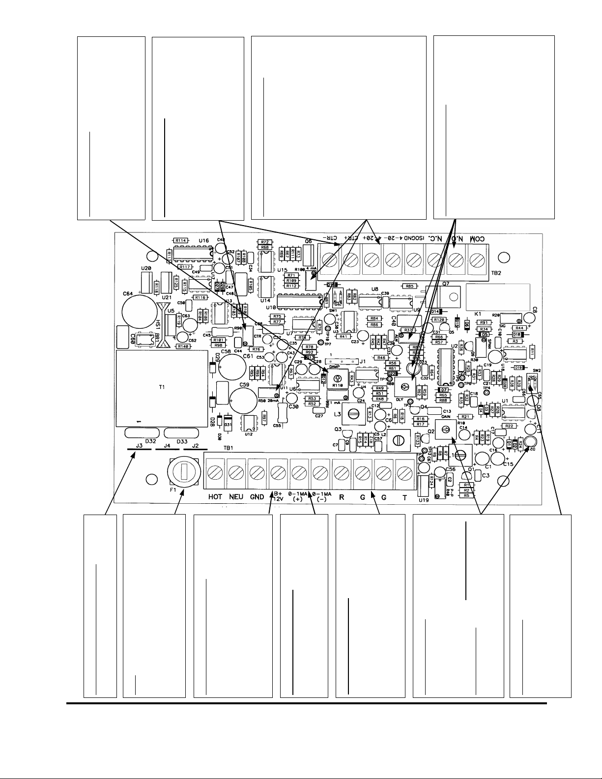
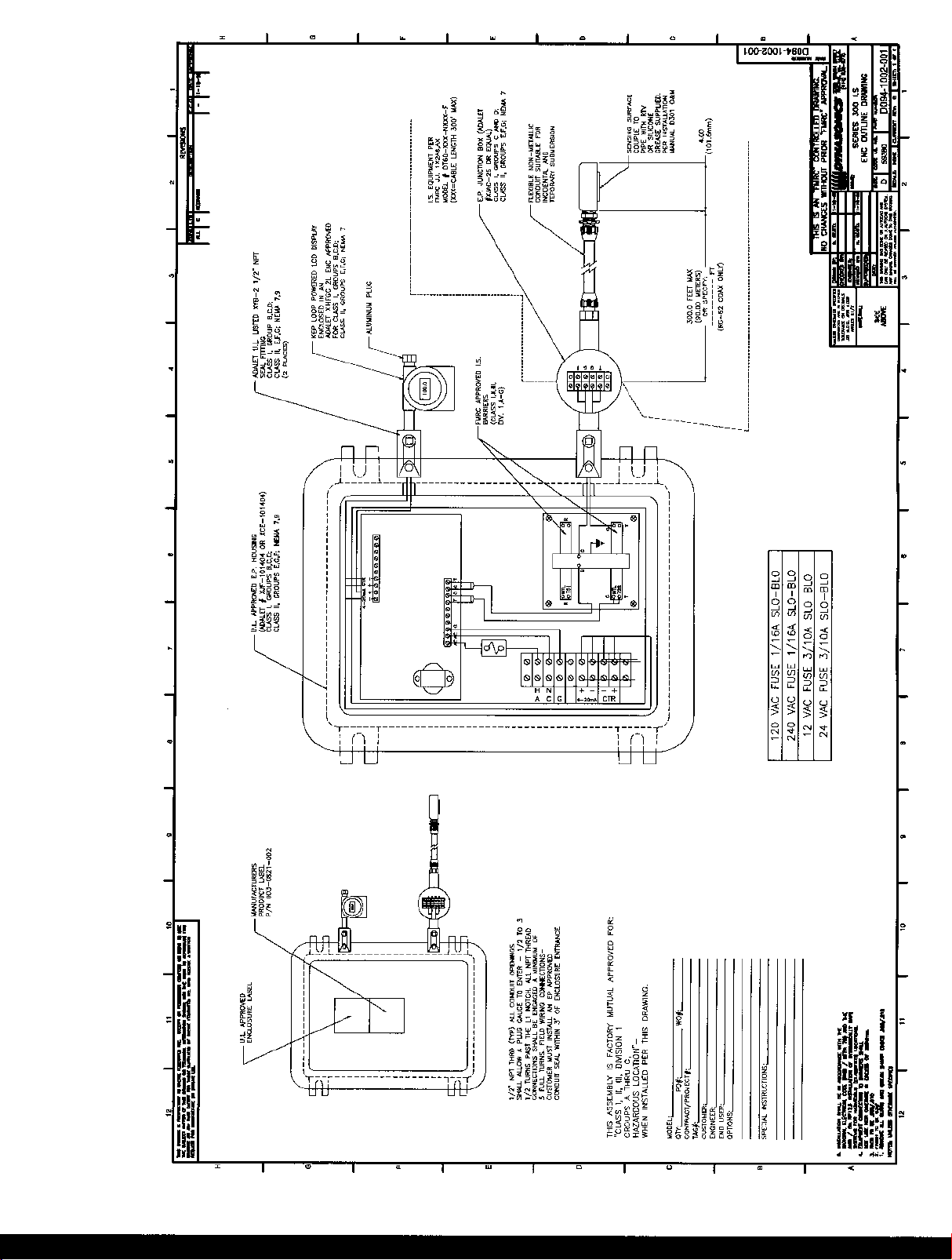
Page 18

02/02/2000
When the D300/D301 i s powered from AC
power sources, 24 Vd c of isolated power
is available at the 4-20mA+ terminal. Sim-
ply connecting the target’s (chart recorder,
data logger, ADC) 4-20mA+ and 4-20mA–
inputs to these two output terminals will
drive 4-20mA through 1000 ohms. •If the target’s internal DC power source is
utilized to power the 4-20mA loop, Con-
nect the ISOGND terminal to the target’s
ground and the target’s 4-20mA input to
the 4-20mA– terminal.
Flow Rate Relay Connections
The D300/D301 is equipped with a flow rate
control relay. The relay is designed to control
loads to 250 Vac and 10A. The relay activates
when the flow rate is less than the set point.
Activation is indicated by D23 [LED]. The relay
setpoint is controlled by adjusting R70 [ALM]
there is also a alarm delay feature that requires
the alarm condition to be present for a period of
time before relay activation. The delay can be
There are two methods to connect this output:
•
R110 [DAMP] Control
Adjust R110 [DAMP] to stabilize flow rate and
output readings. Adj ust CCW to increase the
response of the i nstrum ent; adjust CW to de-
crease response time (smooth the display
readings and outputs).
The CTR output i s designed to operate both
elec tronic and electromech anical t otal izers.
The output can drive loads as low as 90
ohms. Control R90 [CTR] adjusts the span of
this output. Switch set SW1 controls the CTR
CTR Output Connections
output by factors of X1 0. See detai ls in the
Isolated 4-20mA Output Connections
manual describing CTR adjustment.
Control R100 [4mA] is used to adjust 4mA off-
set and R50 [20mA] to adjust 20mA span.
increased by adjusting R80 [DELAY] CW.
Connect the four wires from the two coaxial
cables to the respective terminals. Wire
mar kers on th e coax ial cables id entify the “R”
and the “T” pair. Do not run these cables ad-
Figure 2.2 D301/300 Operated with 115/230 VAC Power Supply
115 Vac J2 and J3 only
230 Vac J4 onl y
Power Supply Jumper Placement
12-24 Vdc Does not matter
Fuse
115/230 Vac 1/16A 3AG
Delay Action
115/230 Vac 50/60 Hz clean AC power re-
quired. Do not connect in parallel with circuits
operating florescent lighting, valves, control
relays, VFDs, etc. GND connection is op-
tional. If GND is connected, verify that it is at
AC Power Connections
the sam e potential as t he piping system.
This output is designed to drive loads up to
1500 ohms. Use R60 [1mA] control to adjust
0-1 mA Output Connection
span.
Transducer Connections
jacent to AC power cables.
R10 [GAIN] Contr ol
After all electrical and transducer connections
have been made, the GAIN control is set to
match liquid and pipe parameters. To prop-
CCW [counter clockwise]. Adjust CW until
D21 [the LED] just begins to flash steadily.
of a flowing liquid. Start with the control fu lly
erly set the R10 [GAIN], the pipe must be full
Rev. 2/00 -3.4- 300/301
LOW Velocity Filter
For meas uring fl uid velociti es up to 20 FP S [ 6
MPS] set the two switches at SW2 to OPEN.
If continuous flow rate will not exceed 2 FPS
[0.6 MPS] turn the two switches ON.
Page 19
02/02/2000
To operate the 4-20mA loop from the
same DC supply operating the flow meter,
connect jumper wires from +B/12V to 4-
20+ and from GND to ISOGND. Connect
the 4-20mA loop load between 4-20+ and
4-20-. •If the target’s (chart recorder, datalogger,
etc.) internal DC power source is utilized
to power the 4-20mA loop, Connect the
ISOGND terminal to the target’s ground,
the target’s +DC output to 4-20+ terminal
and the target’s 4-20mA input to the 4-
20mA– terminal.
The D300/D301 is equipped with a flow rate
control relay. The relay is designed to control
loads to 250 Vac and 10A. The relay activates
when the flow rate is less than the set point.
Activation is indicated by D23 [LED]. The relay
setpoint is controlled by adjusting R70 [ALM]
there is also a alarm delay feature that requires
the alarm condition to be present for a period
of time before relay activation. The delay can
There are two methods to connect this output:
R110 [DAMP] Control
Adjust R110 [DAMP] to stabilize flow rate
and output readings. Adjust CCW to in-
crease the response of the instrument; adjust
CW to decrease response time (smooth the
display readings and outputs).
The CTR output i s designed to operate both
elec tronic and electromech anical t otal izers.
The output can drive loads as low as 90
ohms. Control R90 [CTR] adjusts the span
of this output. Swit ch set SW1 controls the
CTR output by factors of X10. See det ails in
CTR Output Connections
the manual describing CTR adjustment.
•
Isolated 4-20mA Output Connections
Control R100 [4mA] is used to adjust 4mA off-
Flow Rate Relay Connections
set and R50 [20mA] to adjust 20mA span.
be increased by adjusting R80 [DELAY] CW.
Connect the four wires from the two coaxial
cables to the respective terminals. Wire
mar kers on th e coax ial cables id entify the “R”
and the “T” pair. Do not run these cables
Figure 2.3 D301/300 Operated with 12-24 Vdc Power Supply
12-24 Vdc Does not matter
Power Supply Jumper Placement
The fuse provides pr otection for AC pow ered
units only. DC power sources should be
connected with a 0.25A current limiter [fuse]
Fuse
in the positive suppl y line.
Connect a DC power source capable of sourc-
ing 0.2A to the terminals marked +B/12V and
GND. The DC power source will operate all
functions of the D300/D301 except the iso-
lated 4-20mA output. See the box describing
12-24 Vdc Power Connections
Isolated 4-20mA Output for connection details.
This output is designed to drive loads up to
1500 ohms. Use R60 [1mA] control to adjust
0-1 mA Output Connection
Transducer Connections
span.
adjacent to AC power cables.
After al l electri cal and transducer connections
have bee n m ade, the GAIN control is set to
match liquid and pipe parameters. To prop-
R10 [GAIN] Control
erly set the R10 [GAIN], the pipe must be full
of a fl owing liquid. Start with the control fully
CCW [counter clockwise]. Adjust CW until
D21 [the LED] just begins to flash steadily.
Rev. 2/00 -3.5- 300/301
LOW Velocity Filter
For meas uring fluid velocities up to 20 FPS [6
MPS] set the two switches at SW2 to OPEN.
If continuous flow rate will not exceed 2 FPS
[0.6 MPS] turn the two switches ON.
Page 20

PART 4 - CONFIGURATION AND OPERATION
Power Up and GAIN
Adjustment
After power has been applied to the flowmeter and if
the pipe is full of a flowing liquid, the LED l ocated on
the bottom of the main circuit card [D21] should begin
flashing. If the LED does not flash, gradually turn the
GAIN control [R10] clockwise until the LED just
begins to flash steadily. (Do not over adjust this
setting as ambient noise can influence readings.)
If possible, turn off the flow to the pipe. Verify that the
LED [D21] ceases to flash. If the LED continues to
flash when flow rate is zero, the GAIN control [R10] is
set too far clockwise and ambient noise is influencing
the readings. Turn the control counter-clockwise until
the flashing ceases. The indicated flow will take
several seconds to achieve the desired reading
because of the built-in electronic damping circuits.
The flow rate meter is factory calibrated to the pipe
size and flow range indicated on the label located on
the inside front cover of the flow meter.
Totalizer - Series 301 only
Each digit will be in a volumetric unit x 10, x 100, x
1000 or x10,000 as set by SW 1. The totalizer
multiplier that was set at the factory will be indicated
on the label adjacent to the totalizer display. By
changing this switch setting, the totalizer label,
located by the totali zer indicator on the front cover of
the flow meter, will need to be adjusted accordingly.
SW 1—Totalizer Multiplier
SW1-1 SW1-2 MULTIPLIER
OFF OFF X 10
ON OFF X 100
OFF ON X 1000
ON ON X 10000
Rev. 2/00 -4.1- 300/301
Page 21

PART 4 - CONFIGURATION AND OPERATION
FIELD CALIBRATION PROCEDURES
After the Equipment is properly installed and
operating, there may be a need to field calibrate the
flowmeter. This could be caused by a number of
reasons:
1. Using a size pipe other than the one specified
when factory configured.
2. When used to measure a liquid with a sound
speed that is di fferent than the one speci fied when
factory configured.
3. When proper lengths of straight pipe are not
available.
4. Percent of solids are greater than 2%.
5. Operati ng off turbulence or non-linear suspended
solids.
Field Calibration
Procedure
Field Calibration is as follows:
A. To calibrate the flow rate indicators (meter)
against a known flow:
1. With an established flow, the digital readout and/
or current outputs on D300/301 can be adjusted in
accordance with a verified flow measurement, by
adjusting pot R30 (SPAN) adjustment. Turning
the pot C.C.W. decreases the reading. This is a
20 turn, stop-less potentiometer. (Note: Pot R60
will adjust the 0-1 mA output only).
2. It is desired to adjust 4-20 mA to other than
factory calibration, pot R50 can be used to adjust
the 20 mA span.
3. Adjust damping pot R110 for desired flow
response. CW rotation increases flow damping.
The total flow damping range can be varied from
about 5 seconds to 50 seconds. This setting is
usually used to smooth out chart recorder
readings.
Rev. 2/00 -4.2- 300/301
Page 22

PART 4 - CONFIGURATION AND OPERATION
B. Totalizer Calibration — Series 301
1. If an oscilloscope or signal counter is available, a
signal from test point TP10 will show the totalizer
count rate at a particular flow. Refer to the drawing in
the Appendix titled 091-1048-102 Series 300
Waveforms. The pulse rate at TP10 can be x 10, x
100, x 1000 or x10,000 of totalizer count rate, at the
CTR output on terminal strip. For example, if the
pulse rate is 200 milliseconds (multiplier switch SW 1
programmed for 100), then the counter rate at CTR
terminals will be scaled to provide a count every 20
seconds. The total counter output (CTR) range can
be adjusted from approximately 0.5 to 5 seconds wi th
a full scale flow indication.
Totalizer Adjustment:
(CTR CAL) - (pot R90 and DIP SW 1). The mul tiplier
DIP switch SW 1 may be programmed as follows:
SW 1 Posit ion
SW1-1 SW1-2 MULTIPLIER
OFF OFF X 10
ON OFF X 100
OFF ON X 1000
ON ON X 10000
If an oscilloscope or signal counter is not available,
then use the following procedure. The Pot R90 has a
range of 0.5 to 5 seconds. SW1 is then used to
increase this rate all the way up to 50 minutes.
2. Stopwatch Procedure - with a known flow rate
established on the flow meter digital display, time the
count rate on the totali zer by a stopwatch, measuring
the time between totalizer counts. If the totalizer is
reading lower than desired, turn CTR, CAL pot R90
Rev. 2/00 -4.3- 300/301
Page 23

PART 4 - CONFIGURATION AND OPERATION
C.W. Time the new rate and adjust as required. For
example, if the flow indicator reads 1,000 GPM and a
totalizer count rate of 1 count every 60 seconds
should be displayed. If the actual count rate is one
count every 50 seconds, then turn the adjustment
R90 slightly (with SW 1 Position x 1,000) C.C.W. to
decrease the count rate until there is one count on
the totalizer every 60 seconds when the flow rate
indicator is reading 1,000 GPM. As noted above, 20
full turns on R90 will produce a variation in count rate
of at least x 10, or from approximately 50 to 500
seconds when the indicator is reading full scale. To
determine count rate:
60 (TM)
Count rate = ---------------- GPM
Where,
TM = totalizer multiplier or gallons x totalizer counts
GPM = flow at time of calibration
Electronic Calibration
The flowmeter is electronically calibrated at the
factory by calculating the fluid velocity in Feet per
Second (FPS) that corresponds to the pipe size and
volumetric flow rate that was customer supplied at the
time of the order. The following equations were used
to determine the “calibration frequency” that is
required to properly span the flow meter.
FPS = GPM
(PIPE I.D.)
Where
PIPE I.D. is inches
A DT6 transducer generates 120 Hz / 1 FPS of
frequency shift when operated on room temperature
water. Alternate fluids can influence this factor. See
2
X 2.45
Rev. 2/00 -4.4- 300/301
Page 24

PART 4 - CONFIGURATION AND OPERATION
the Fluid Sound Speed Compensation chart located
in the Appendix of this manual.
Once a new calibration frequency has been
determined, the frequency is input as a 1 Vpp sinewave into TP3 on the main circuit card. This input will
simulate full scale flow in the circuit. With the function
generator inputting the calibration frequency the
SPAN, 1mA, 20mA and CTR inputs can be
configured. A 10% and 50% of SPAN frequency ca n
be input and flow meter linearity can be verified.
Noise and Gain Adju st
If meter indicates a reading with no flow, turn R10
(GAIN) C.C.W. just enough to eliminate. Since this
reduces sensitivity, do not turn past point of proper
operation. If indicator will not read flow, turn R10
(GAIN) C.W.
Relay Adjustment
1. Turn R80 (DLY) fully CCW for minimum delay (2
sec.) before proceeding with alarm trip
adjustments.
2. For a point of reference, turn R70 (ALM) al so fully
CCW.
3. At the desired flow dropout (which can be
simulated by the procedure covered in the
Electronic Calibration Procedure on Page 4.4),
slowly (due to time delay) adjust alarm R70 (ALM)
CW until relay is deactivated. Do not overturn.
NOTE:
the flow switch system at 1 FPS.
4. After a desired alarm trip point is established,
adjust R80 (DLY) CW for a desired ti me delay (20
sec. Max. On flow dropouts).
Rev. 2/00 -4.5- 300/301
About 10% flow hysteresi s is built-in into
Page 25

PART 4 - CONFIGURATION AND OPERATION
HOW TO CALIBRATE FOR A DIFFERENT SCALE
& PIPE
This procedure is an outline of how to re-scale the
series D300/301 flow meter.
1. The first step is to determine the full scale velocity
setting. To determine this you would need the full
scale setting (i.e. GPM, MGD etc) and the pi pe inside
diameter (refer to the charts in the Appendix).
Example calculation: Full scale 500 GPM. Pipe size:
4.026 inches I.D.
Feet per Second = 500 GPM = 12.755 FPS
(4.026)2 x 2.45
2. Multiply the Full Scale in FPS by 120 Hertz.
12.755 * 120 = 1530 Hertz.
3. As described in the Electroni c Cali bration section
on page 4.4 of this operations manual, input a 1Vpp
sine-wave at 1530 Hz into TP3 to simul ate full scale
flow.
4. Adjust R30 (SPAN) for 5.0 VDC at TP7. On A
D301 meter adjust the digital indicator located on the
door of the instrument. The adjustments for the
scaling on the digi tal in dic ator are also labeled SPAN.
The fine adjustment on the digital indicator is labeled
CAL. Use both of these adjustments to correctly set
the indicator.
5. On a D301 equipped with a totalizer the new count
rate would be determined by the following example:
60/500 = 0.12 sec per count. In this example it has
been determined that 1 count at .12 sec per count is
equal to 1 gallon. Since 0.12 seconds is too fast for
the electronic circuit design (i.e. 0.5 sec minimum
setting), the decimal place is moved over one and
Rev. 2/00 -4.6- 300/301
Page 26

PART 4 - CONFIGURATION AND OPERATION
the new count rate is 1.2 seconds per count at 10
gallons per count.
A digital counter is placed on the output of the circuit
card to measure the period between pulses so that at
a full scale of 500 GPM the CTR adjustment i s set to
correspond to a 1.2 second period interval. The SW1
switch is only used if the customer wishes to set the
gallons per count rate higher (i.e. x 10, x 100, x
1000).
Rev. 2/00 -4.7- 300/301
Page 27

Cement Lining
Ductile Iron Pipe
Standard Classes
Pipe
Size
(inches)
3 3.96 3.46 0.25 3.40 0.28 3.34 0.31 3.28 0.34 3.22 0.37 3.14 0.41
4 4.80 4.28 0.26 4.22 0.29 4.16 0.32 4.10 0.35 4.04 0.38 3.93 0.44
6 6.90 6.40 0.25 6.34 0.28 6.28 0.31 6.22 0.34 6.16 0.37 6.10 0.40 6.04 0.43 .123/.250
8 9.05 8.51 0.27 8.45 0.30 8.39 0.33 8.33 0.36 8.27 0.39 8.21 0.42 8.15 0.45
10 11.10 10.32 0.39 10.46 0.32 10.40 0.35 10.34 0.38 10.28 0.41 10.22 0.44 10.16 0.47
12 13.20 12.58 0.31 12.52 0.34 12.46 0.37 12.40 0.40 12.34 0.43 12.28 0.46 12.22 0.49
14 15.30 14.64 0.33 14.58 0.36 14.52 0.39 14.46 0.42 14.40 0.45 14.34 0.48 14.28 0.51
16 17.40 16.72 0.34 16.66 0.37 16.60 0.40 16.54 0.43 16.48 0.46 16.42 0.49 16.36 0.52
18 19.50 18.80 0.35 18.74 0.38 18.68 0.41 18.62 0.44 18.56 0.47 18.50 0.50 18.44 0.53 .1875/.375
20 21.60 20.88 0.36 20.82 0.39 20.76 0.42 20.70 0.45 20.64 0.48 20.58 0.51 20.52 0.54
24 25.80 25.04 0.38 24.98 0.41 24.92 0.44 24.86 0.47 24.80 0.50 24.74 0.53 24.68 0.56
30 32.00 31.22 0.39 31.14 0.43 31.06 0.47 30.98 0.51 30.90 0.55 30.82 0.59 30.74 0.63
Outside
Diameter
(inches)
Class 53
ID Wall ID Wall ID Wall ID Wall ID Wall ID Wall ID Wall
Class 54 Class 55 Class 56Class 50 Class 51 Class 52
Std./Double
Thickness
36 38.30 37.44 0.43 37.34 0.48 37.06 0.62 37.14 0.58 37.40 0.45 36.94 0.68 36.84 0.73
42 44.50 43.56 0.47 43.44 0.53 43.32 0.59 43.20 0.65 43.08 0.71 42.96 0.77 42.84 0.83 .250/.500
48 50.80 49.78 0.51 49.64 0.58 49.50 0.65 49.36 0.72 49.22 0.79 49.08 0.86 48.94 0.93
54 57.10 55.96 0.57 55.80 0.65 55.64 0.73 55.48 0.81 55.32 0.89 55.16 0.97 55.00 1.05
March, 2000
Page 28

Cast Iron Pipe
Standard Classes
CLASS B CLASS C CLASS D CLASS E CLASS F CLASS G CLASS HCLASS A
Size
(Inches)
10 11.10 10.10 0.50 11.10 9.96 0.57 11.40 10.16 0.62 11.40 10.04 0.68 11.60 10.12 0.74 11.60 10.00 0.80 11.84 10.12 0.86 11.84 10.00 0.92
12 13.20 12.12 0.54 13.20 11.96 0.62 13.50 12.14 0.68 13.50 12.00 0.75 13.78 12.14 0.82 13.78 12.00 0.89 14.08 12.14 0.97 14.08 12.00 1.04
14 15.30 14.16 0.57 15.30 13.98 0.66 15.65 14.17 0.74 15.65 14.01 0.82 15.98 14.18 0.90 15.98 14.00 0.99 16.32 14.18 1.07 16.32 14.00 1.16
16 17.40 16.20 0.60 17.40 16.00 0.70 17.80 16.20 0.80 17.80 16.02 0.89 18.16 16.20 0.98 18.16 16.00 1.08 18.54 16.18 1.18 18.54 16.00 1.27
18 19.50 18.22 0.64 19.50 18.00 0.75 19.92 18.18 0.87 19.92 18.00 0.96 20.34 18.20 1.07 20.34 18.00 1.17 20.78 18.22 1.28 20.78 18.00 1.39
20 21.60 20.26 0.67 21.60 20.00 0.80 22.06 20.22 0.92 22.06 20.00 1.03 22.54 20.24 1.15 22.54 20.00 1.27 23.02 20.24 1.39 23.02 20.00 1.51
24 25.80 24.28 0.76 25.80 24.02 0.89 26.32 24.22 1.05 26.32 24.00 1.16 26.90 24.28 1.31 26.90 24.00 1.45 27.76 24.26 1.75 27.76 24.00 1.88
30 31.74 29.98 0.88 32.00 29.94 1.03 32.40 30.00 1.20 32.74 30.00 1.37 33.10 30.00 1.55 33.46 30.00 1.73
36 37.96 35.98 0.99 38.30 36.00 1.15 38.70 35.98 1.36 39.16 36.00 1.58 39.60 36.00 1.80 40.04 36.00 2.02
42 44.20 42.00 1.10 44.50 41.94 1.28 45.10 42.02 1.54 45.58 42.02 1.78
48 50.50 47.98 1.26 50.80 47.96 1.42 51.40 47.98 1.71 51.98 48.00 1.99
O.D.
Inch
3 3.80 3.02 0.39 3.96 3.12 0.42 3.96 3.06 0.45 3.96 3.00 0.48
4 4.80 3.96 0.42 5.00 4.10 0.45 5.00 4.04 0.48 5.00 3.96 0.52
6 6.90 6.02 0.44 7.10 6.14 0.48 7.10 6.08 0.51 7.10 6.00 0.55 7.22 6.06 0.58 7.22 6.00 0.61 7.38 6.08 0.65 7.38 6.00 0.69
8 9.05 8.13 0.46 9.05 8.03 0.51 9.30 8.18 0.56 9.30 8.10 0.60 9.42 8.10 0.66 9.42 8.10 0.66 9.60 8.10 0.75 9.60 8.00 0.8
I.D.
Inch
Wall
O.D.
Inch
I.D.
Inch
Wall
O.D.
Inch
I.D.
Inch
Wall
O.D.
Inch
I.D.
Inch
Wall
O.D.
Inch
I.D.
Inch
Wall
O.D.
Inch
I.D.
Inch
Wall
O.D.
Inch
I.D.
Inch
Wall
O.D.
Inch
I.D.
Inch
Wall
54 56.66 53.96 1.35 57.10 54.00 1.55 57.80 54.00 1.90 58.40 53.94 2.23
60 62.80 60.02 1.39 63.40 60.06 1.67 64.20 60.20 2.00 64.82 60.06 2.38
72 75.34 72.10 1.62 76.00 72.10 1.95 76.88 72.10 2.39
84 87.54 84.10 1.72 88.54 84.10 2.22
March, 2000
Page 29

Steel, Stainless Steel, P.V.C.
Standard Schedules
Nominal
Pipe Size
Inches
OUTSIDE
DIAMETER
1 1.315 1.185 0.065 1.097 0.109 1.049 1.049 0.133 0.957 0.179 0.957 0.179 0.815 0.250
1.25 1.660 1.530 0.065 1.442 0.109 1.380 1.380 0.140 1.278 0.191 1.278 0.191 1.160 0.250
1.5 1.900 1.770 0.065 1.682 0.109 1.610 1.610 0.145 1.500 0.200 1.500 0.200 1.338 0.281
2 2.375 2.245 0.065 2.157 0.109 2.067 2.067 0.154 1.939 0.218 1.939 0.218 1.687 0.344
2.5 2.875 2.709 0.083 2.635 0.120 2.469 2.469 0.203 2.323 0.276 2.323 0.276 2.125 0.375
3 3.500 3.334 0.083 3.260 0.120 3.068 3.068 0.216 2.900 0.300 2.900 0.300 2.624 0.438
3.5 4.000 3.834 0.083 3.760 0.120 3.548 3.548 0.226 3.364 0.318 3.364 0.318
4 4.500 4.334 0.083 4.260 0.120 4.026 0.237 4.026 0.237 3.826 0.337 3.826 0.337 3.624 0.438 3.624 0.438 3.438 0.531
5 5.563 5.345 0.109 5.295 0.134 5.047 0.258 5.047 0.258 4.813 0.375 4.813 0.375 4.563 0.500 4.563 0.500 4.313 0.625
6 6.625 6.407 0.109 6.357 0.134 6.065 0.280 6.065 0.280 5.761 0.432 5.761 0.432 5.501 0.562 5.501 0.562 5.187 0.719
8 8.625 8.407 0.109 8.329 0.148 8.125 0.250 8.071 0.277 7.981 0.322 7.981 0.322 7.813 0.406 7.625 0.500 7.625 0.500 7.437 0.594 7.187 0.719 7.187 0.719 6.183 1.221
10 10.750 10.482 0.134 10.42 0.165 10.25 0.250 10.13 0.310 10.02 0.365 10.020 0.365 9.750 0.500 9.750 0.500 9.562 0.594 9.312 0.719 9.062 0.844 9.062 0.844 8.500 1.125
12 12.750 12.420 0.165 12.39 0.180 12.25 0.250 12.09 0.330 12.00 0.375 11.938 0.406 11.626 0.562 11.750 0.500 11.370 0.690 11.060 0.845 10.750 1.000 10.750 1.000 10.120 1.315
14 14.000 13.50 0.250 13.37 0.315 13.25 0.375 13.25 0.375 13.124 0.438 12.814 0.593 13.000 0.500 12.500 0.750 12.310 0.845 11.810 1.095 11.810 1.095 11.180 1.410
16 16.000 15.50 0.250 15.37 0.315 15.25 0.375 15.25 0.375 15.000 0.500 14.688 0.656 15.000 0.500 14.310 0.845 13.930 1.035 13.560 1.220 13.560 1.220 12.810 1.595
18 18.000 17.50 0.250 17.37 0.315 17.12 0.440 17.25 0.375 16.876 0.562 16.564 0.718 17.000 0.500 16.120 0.940 15.680 1.160 15.250 1.375 15.250 1.375 14.430 1.785
20 20.000 19.50 0.250 19.25 0.375 19.25 0.375 19.25 0.375 18.814 0.593 18.376 0.812 19.000 0.500 17.930 1.035 17.430 1.285 17.000 1.500 17.000 1.500 16.060 1.970
24 24.000 23.50 0.250 23.25 0.375 23.25 0.375 23.25 0.375 22.626 0.687 22.126 0.937 23.000 0.500 21.560 1.220 20.930 1.535 20.930 1.535 20.930 1.535 19.310 2.345
30 30.000 29.37 0.315 29.00 0.500 29.00 0.500 29.25 0.375 29.250 0.375 29.000 0.500
36 36.000 35.37 0.315 35.00 0.500 35.00 0.500 35.25 0.375 35.250 0.375 35.000 0.500
42 42.000 41.25 0.375 41.250 0.375 41.000 0.500
48 48.000 47.25 0.375 47.250 0.375 47.000 0.500
SCH.
5
ID Wall ID Wall ID Wall ID Wall ID Wall ID Wall ID Wall ID Wall ID Wall ID Wall ID Wall ID Wall ID Wall
SCH. 10
(LTWALL)
SCH. 20 SCH. 30 STD. SCH. 40 SCH. 60 SCH. 140 SCH. 180
X STG. SCH. 80 SCH. 100 SCH. 120
March, 2000
Page 30

FPS TO GPM CROSS - REFERENCE (Schedule 40)
Nominal
Pipe
(Inches)
1 1.05 2.6989 4.0484 5.3978 6.7473 8.097 9.4462 10.796 12.145 13.490 14.844 16.190 17.540 18.890 20.240 21.590 22.941 24.290
1.25 1.38 4.6620 6.9929 9.3239 11.655 13.99 16.317 18.648 20.979 23.310 25.641 27.970 30.300 32.630 34.960 37.300 39.627 41.958
1.5 1.61 6.3454 9.5182 12.691 15.864 19.04 22.209 25.382 28.555 31.730 34.900 38.070 41.250 44.420 47.590 50.760 53.936 57.109
2 2.07 10.489 15.734 20.979 26.224 31.47 36.713 41.958 47.202 52.450 57.692 62.940 68.180 73.430 78.670 83.920 89.160 94.405
2.5 2.47 14.935 22.402 29.870 37.337 44.80 52.272 59.740 67.207 74.670 82.142 89.610 97.080 104.50 112.00 119.50 126.95 134.41
3 3.07 23.072 34.608 46.144 57.680 69.22 80.752 92.288 103.82 115.40 126.90 138.40 150.00 161.50 173.00 184.60 196.11 207.65
3.5 3.55 30.851 46.276 61.702 77.127 92.55 107.98 123.40 138.83 154.30 169.68 185.10 200.50 216.00 231.40 246.80 262.23 277.66
4 4.03 39.758 59.636 79.515 99.394 119.3 139.15 159.03 178.91 198.80 218.67 238.50 258.40 278.30 298.20 318.10 337.94 357.82
5 5.05 62.430 93.645 124.86 156.07 187.3 218.50 249.72 280.93 312.10 343.36 374.60 405.80 437.00 468.20 499.40 530.65 561.87
6 6.06 89.899 134.85 179.80 224.75 269.7 314.65 359.60 404.55 449.50 494.45 539.40 584.30 629.30 674.20 719.20 764.14 809.09
8 7.98 155.89 233.83 311.78 389.72 467.7 545.61 623.56 701.50 779.40 857.39 935.30 1013.0 1091.0 1169.0 1247.0 1325.1 1403.0
10 10.02 245.78 368.67 491.56 614.45 737.3 860.23 983.12 1106.0 1229.0 1351.8 1475.0 1598.0 1720.0 1843.0 1966.0 2089.1 2212.0
I.D.
INCH
1 1.5 2 2.5 3 3.5 4 4.5 5 5.5 6 6.5 7 7.5 8 8.5 9
12 11.94 348.99 523.49 697.99 872.49 1047.0 1221.5 1396.0 1570.5 1745.0 1919.5 2094.0 2268.0 2443.0 2617.0 2792.0 2966.5 3141.0
14 13.13 422.03 633.04 844.05 1055.1 1266.0 1477.1 1688.1 1899.1 2110.0 2321.1 2532.0 2743.0 2954.0 3165.0 3376.0 3587.2 3798.2
16 15.00 550.80 826.20 1101.6 1377.0 1652.0 1927.8 2203.2 2478.6 2754.0 3029.4 3305.0 3580.0 3856.0 4131.0 4406.0 4681.8 4957.2
FPS TO GPM: GPM = (PIPE ID)² X VELOCITY IN FPS X 2.45 FPS X .3048 = MPS
GPM TO FPS: FPS =
GPM
(ID)² X 2.45
GPM X .0007 = GPD
GPM X 3.7878 = LPM
Page 31

FPS TO GPM CROSS - REFERENCE (Schedule 40)
Nominal
Pipe
(Inches)
18 16.88 697.52 1046.3 1395.0 1743.8 2093.0 2441.3 2790.1 3138.8 3488.0 3836.3 4185.0 4534.0 4883.0 5231.0 5580.0 5928.9 6277.7
20 18.81 866.14 1299.0 1732.0 2165.3 2598.4 3031.5 3464.6 3897.6 4330.7 4763.8 5196.8 5629.9 6063.0 6496.0 6929.1 7362.2 7795.3
24 22.63 1253.7 1880.0 2507.0 3134.1 3761.0 4387.8 5014.6 5641.5 6268.3 6895.1 7522.0 8148.8 8775.6 9402.4 10029 10656 11283
26 25.25 1560.7 2341.0 3121.0 3901.9 4682.2 5462.6 6243.0 7023.4 7803.7 8584.1 9364.5 10145 10925 11706 12486 13266 14047
28 27.25 1817.8 2727.0 3636.0 4544.5 5453.4 6362.3 7271.2 8180.0 9088.9 9997.8 10907 11816 12725 13633 14542 15451 16360
30 29.25 2094.4 3142.0 4189.0 5236.0 6283.2 7330.4 8377.6 9424.9 10472 11519 12566 13614 14661 15708 16755 17803 18850
32 31.25 2390.6 3586.0 4781.0 5976.5 7171.9 8367.2 9562.5 10758 11953 13148 14344 15539 16734 17930 19125 20320 21516
34 33.25 2706.4 4060.0 5413.0 6766.0 8119.2 9472.4 10826 12179 13532 14885 16238 17592 18945 20298 21651 23004 24358
36 35.25 3041.8 4563.0 6084.0 7604.5 9125.4 10646 12167 13688 15209 16730 18251 19772 21292 22813 24334 25855 27376
42 41.25 4165.4 6248.0 8331.0 10414 12496 14579 16662 18744 20827 22910 24992 27075 29158 31241 33323 35406 37489
48 47.99 5637.8 8457.0 11276 14095 16913 19732 22551 25370 28189 31008 33827 36646 39465 42284 45103 47922 50740
54 53.98 7133.1 10700 14266 17833 21399 24966 28532 32099 35665 39232 42798 46365 49931 53498 57065 60631 64198
I.D.
INCH
1 1.5 2 2.5 3 3.5 4 4.5 5 5.5 6 6.5 7 7.5 8 8.5 9
60 60.09 8839.2 13259 17678 22098 26518 30937 35357 39777 44196 48616 53035 57455 61875 66294 70714 75134 79553
72 72.10 12726 19089 25451 31814 38177 44540 50903 57266 63628 69991 76354 82717 89080 95443 101805 108168 114531
84 84.10 17314 25971 34628 43285 51943 60600 69257 77914 86571 95228 103885 112542 121199 129856 138514 147171 155828
FPS TO GPM: GPM = (PIPE ID)² X VELOCITY IN FPS X 2.45 FPS X .3048 = MPS
GPM TO FPS: FPS =
GPM
(ID)² X 2.45
GPM X .0007 = GPD
GPM X 3.7878 = LPM
Page 32

Fluid Sound Speeds
g
Original Date: 10/19/99
Revision: none
Revision Date: none
File: I:/dynasonics/dyna_code/tables/doppler ss conversions.xls
120.0176921
Doppler
Fluid Specific Gravity Sound Speed Calibration Entry
20 de
Acetate, Butyl (n) 1270 4163.9 85
Acetate, Ethyl 0.901 1085 3559.7 72
Acetate, Methyl 0.934 1211 3973.1 81
Acetate, Propyl 1280 4196.7 85
Acetone 0.79 1174 3851.7 78
Alcohol 0.79 1207 3960.0 81
Alcohol, Butyl (n) 0.83 1270 4163.9 85
Alcohol, Ethyl 0.83 1180 3868.9 79
Alcohol, Methyl 0.791 1120 3672.1 75
Alcohol, Propyl (I) 1170 3836.1 78
Alcohol, Propyl (n) 0.78 1222 4009.2 82
Ammonia (35) 0.77 1729 5672.6 115
Anlline (41) 1.02 1639 5377.3 109
Benzene (29,40,41) 0.88 1306 4284.8 87
Benzol, Ethyl 0.867 1338 4389.8 89
Bromine (21) 2.93 889 2916.7 59
n-Butane (2) 0.60 1085 3559.7 72
Butyrate, Ethyl 1170 3836.1 78
Carbon dioxide (26) 1.10 839 2752.6 56
Carbon tetrachloride 1.60 926 3038.1 62
Chloro-benezene 1.11 1273 4176.5 85
Chloroform (47) 1.49 979 3211.9 65
Diethyl ether 0.71 985 3231.6 66
Diethyl Ketone 1310 4295.1 87
Diethylene glycol 1.12 1586 5203.4 106
Ethanol 0.79 1207 3960.0 81
Ethyl alcohol 0.79 1207 3960.0 81
Ether 0.71 985 3231.6 66
Ethyl ether 0.71 985 3231.6 66
Ethylene glycol 1.11 1658 5439.6 111
Freon R12 774.2 2540 52
Gasoline 0.7 1250 4098.4 83
Glycerin 1.26 1904 6246.7 127
Glycol 1.11 1658 5439.6 111
Isobutanol 0.81 1212 3976.4 81
Iso-Butane 1219.8 4002 81
Isopentane (36) 0.62 980 3215.2 65
Isopropanol (46) 0.79 1170 3838.6 78
Isopropyl alcohol (46) 0.79 1170 3838.6 78
Kerosene 0.81 1324 4343.8 88
Linalool 1400 4590.2 93
rees C m/s ft/s relative to 25C water
Page 33

Linseed Oil .925-.939 1770 5803.3 118
(
)
Methanol (40,41) 0.79 1076 3530.2 72
Methyl alcohol (40,44) 0.79 1076 3530.2 72
Methylene chloride (3) 1.33 1070 3510.5 71
Methylethyl Ketone 1210 3967.2 81
Motor Oil (SAE 20/30) .88-.935 1487 4875.4 99
Octane (23) 0.70 1172 3845.1 78
Oil, Castor 0.97 1477 4845.8 99
Oil, Diesel 0.80 1250 4101 83
Oil (Lubricating X200) 1530 5019.9 102
Oil (Olive) 0.91 1431 4694.9 96
Oil (Peanut) 0.94 1458 4783.5 97
Paraffin Oil 1420 4655.7 95
Pentane 0.626 1020 3346.5 68
Petroleum 0.876 1290 4229.5 86
1-Propanol (46) 0.78 1222 4009.2 82
Refrigerant 11 (3,4) 1.49 828.3 2717.5 55
Refrigerant 12 (3) 1.52 774.1 2539.7 52
Refrigerant 14 (14) 1.75 875.24 2871.5 58
Refrigerant 21 (3) 1.43 891 2923.2 59
Refrigerant 22 (3) 1.49 893.9 2932.7 60
Refrigerant 113 (3) 1.56 783.7 2571.2 52
Refrigerant 114 (3) 1.46 665.3 2182.7 44
Refrigerant 115 (3) 656.4 2153.5 44
Refrigerant C318 (3) 1.62 574 1883.2 38
Silicone (30 cp) 0.99 990 3248 66
Toluene (16,52) 0.87 1328 4357 89
Transformer Oil 1390 4557.4 93
Trichlorethylene 1050 3442.6 70
1,1,1-Trichloro-ethane 1.33 985 3231.6 66
Turpentine 0.88 1255 4117.5 84
Water, distilled
Water 0 degrees C 1402 4596.7 94
Water 20 degrees C 1482 4859.0 99
Water 40 degrees C 1529 5013.1 102
Water 60 degrees C 1551 5085.2 103
Water 80 degrees C 1554 5095.1 104
Water 100 degrees C 1543 5059.0 103
Water 120 degrees C 1519 4980.3 101
Water 140 degrees C 1485 4868.9 99
Water 160 degrees C 1440 4721.3 96
Water 180 degrees C 1390 4557.4 93
Water 200 degrees C 1333 4370.5 89
Water, heavy 1 1400 4593 93
Water, sea 1.025 1531 5023 102
Wood Alcohol (40,41) 0.791 1076 3530.2 72
m-Xylene (46) 0.868 1343 4406.2 90
o-Xylene (29,46) 0.897 1331.5 4368.4 89
p-Xylene (46) 1334 4376.8 89
49,50
0.996 1498 4914.7 100
Page 34

Page 35

Page 36
Page 37

Page 38
 Loading...