

Dynaset HVB 350/9-40, HVD 18/55-24, HVB 350/18-60, HVD 70/35-100, HVB 350/27-80 User Manual
USER MANUAL
06/18
rev 1.2
HYDRAULIC VIBRAS
HVB 350/9-40
HVB 350/18-60
HVB 350/27-80
Download PDF version from www.Dynaset.com/manuals Keycode: NJ4VL3
HVD 18/55-24
HVD 70/35-100

Congratulations!
You have just purchased DYNASET hydraulic equipment!
The equipment allows you to maximize the productivity and
efficiency of your mobile machine. Read this User Manual
before using your new equipment. It contains important
information that will help you to take the full advance of the
technical features avaible in your equipment.
Please contact us for any feedback you might have on our
products. Your feedback is important to us for improving our
products and customer service.
We are constantly developing and releasing new innovations.
Please visit on our website and social media channels for the
latest news and updates.
www.dynaset.com
info@dynaset.com
www.facebook.com/dynaset
www.youtube.com/dynasetoy
www.twitter.com/Dynaset_ofcl
www.instagram.com/dynaset_official
Subscribe to our newsletter. Follow the QR
code!
Dynaset Oy | Menotie 3, FI-33470 Ylöjärvi, Finland | tel: +358 3 3488 200 | info@dynaset.com | www.dynaset.com
3
HYDRAULIC VIBRAS
TABLE OF CONTENTS
1. GENERAL 9
1.1. PRODUCT INFORMATION 9
1.2. PRODUCT IDENTIFICATION KEY 10
1.3. TYPE PLATE 11
1.4. HVB AND HVD LINE-UP 12
1.5. MAIN COMPONENTS OF HVB 12
1.6. MAIN COMPONENTS OF HVD 13
2. SAFETY 15
2.1. SAFETY PRECAUTIONS 15
2.2. SAFETY EQUIPMENT 15
2.3. OPERATING SAFETY 16
2.4. MAINTENANCE SAFETY 16
2.5. WARNING LABELS 17
3. OPERATING PRINCIPLES 19
3.1. OPERATING DESCRIPTION 19
4. INSTALLATION 21
4.1. BEFORE INSTALLATION 21
HYDRAULIC FLUIDS 21
4.2. INSTALLATION OF HVB UNIT 21
4.3. INSTALLATION OF HVD 25
4.4. ELECTRIC CONNECTIONS 29
5. OPERATION 31
5.1. OPERATING HVB AND HVD UNITS 31
6. MAINTENANCE 33
6.1. MAINTENANCE INTERVAL 33
6.2. HYDRAULIC FLUIDS 33
6.3. CLEANING THE HVB AND HVD UNITS 34
6.4. REPLACING SEALS AND INTAKE VALVES TO HVB 34
6.5. REPLACING SEALS AND INTAKE VALVES TO HVD 39
6.6. BOLT TIGHTENING TORQUES 42
6.7. TROUBLESHOOTING 43
Dynaset Oy | Menotie 3, 33470 Ylöjärvi | puh. 03 3488 200 | info@dynaset.com | www.dynaset.com

HYDRAULIC VIBRAS
TABLE OF CONTENTS
7. MANUFACTURER’S LIMITED WARRANTY 45
8. PRODUCT DISPOSAL 47
9. DECLARATION OF CONFORMITY 49
10. TECHNICAL SPECIFICATIONS 51
Dynaset Oy | Menotie 3, 33470 Ylöjärvi | puh. 03 3488 200 | info@dynaset.com | www.dynaset.com
HYDRAULIC VIBRAS
TABLE OF PICTURES
Picture 1: Identication key for HVB 10
Picture 2: Identication key for HVD 10
Picture 3: HVB Type plate 11
Picture 4: HVD Type plate 11
Picture 5: HVB and HVD line-up 12
Picture 6: Main components of HVB 12
Picture 7: Main components of HVD 13
Picture 8: Operating description of HVB 19
Picture 9: Operating description of HVD 20
Picture 10: HVB installation 21
Picture 11: Installation of HVB to existing tool line 22
Picture 12: Installation of HVB with DYNASET PV-SAE priority valve 23
Picture 13: Installation of HVB with DYNASET LSV valve and switch 24
Picture 14: Installation position 25
Picture 15: Installing HVD and installation plate 25
Picture 16: Installation of HVD to existing tool line 26
Picture 17: Installation of HVD with DYNASET PV-SAE priority valve 27
Picture 18: Installation of HVD with DYNASET LSV valve and switch 28
Picture 19: Electric schema for solenoid valve 29
Picture 20: Operating HVB and HVD units 31
Picture 21: Removing the pump head 34
Picture 22: Removing the pump head and intake valve 34
Picture 23: Positioning the body 35
Picture 24: Removing the piston 35
Picture 25: Removing the piston from the cylider 35
Picture 26: Removing seals from piston and the cylinder 36
Picture 27: Installing the seals to piston and the cylinder 36
Picture 28: Lubricating the piston and the cylinder 36
Picture 29: Installing the piston assembly to the pump body 1 37
Picture 30: Installing the piston assembly to the pump body 2 37
Picture 31: Removing the pump head seals 38
Picture 32: Installing the pump heads 38
Picture 33: Removing the pump head 39
Picture 34: Removing the body seals and the piston 39
Picture 35: Removing piston shell 40
Picture 36: Replacing and lubricating piston assembly seals 40
Picture 37: Installing piston 40
Picture 38: Replacing and lubricating head seals 41
Picture 39: Installing body seals and head 41
Picture 40: Tightening the screws 42
Dynaset Oy | Menotie 3, 33470 Ylöjärvi | puh. 03 3488 200 | info@dynaset.com | www.dynaset.com

HYDRAULIC VIBRAS
TABLE OF PICTURES
Dynaset Oy | Menotie 3, 33470 Ylöjärvi | puh. 03 3488 200 | info@dynaset.com | www.dynaset.com

HYDRAULIC VIBRAS
TABLE OF PICTURES
Dynaset Oy | Menotie 3, 33470 Ylöjärvi | puh. 03 3488 200 | info@dynaset.com | www.dynaset.com

1. GENERAL
This manual contains general information about assembly, installation, operation
and maintenance of the DYNASET HVB Hydraulic Vibration Pump and DYNASET
HVD Hydraulic Directional Vibra.
ATTENTION!
Read this user manual before installation, use or maintenance of the HVB
and HVD to ensure proper handling, operation and maintenance right
from the beginning. Pay attention to warnings and safety instructions.
READ CHAPTER ”2. SAFETY” for more information.
HYDRAULIC VIBRAS
GENERAL
1.1. PRODUCT INFORMATION
DYNASET HVB Hydraulic Vibration Pump is connected to the base machines
hydraulic cylinder that operates the tool e.g. bucket. Activating HVB it creates
fast back-forth movement to the cylinder resulting vibration to the tool. HVBs can
create up to 30 Hz vibration. The Vibration power depends on the cylinders max.
power. HVB is a great for enhancing bucket emptying, increasing frozen ground
penetration, soil compacting and pile driving.
DYNASET HVD Hydraulic Directional Vibra is installed straigth to the tool e.g. to a
bucket. HVDs produce powerful directional vibration for buckets, street cleaning
units, soil compacting etc. HVD vibras create up to 70kN power with 35 Hz
frequence.
Dynaset Oy | Menotie 3, 33470 Ylöjärvi | puh. 03 3488 200 | info@dynaset.com | www.dynaset.com
9

1.2. PRODUCT IDENTIFICATION KEY
The product identification key describes the characteristics of the DYNASET
product. The product identification key is on the product type plate which is
attached onto every DYNASET product.
Picture 1: Identification key for HVB
1. Product Group in this case HVB Hydraulic Vibration Pump
2. Maximum hydraulic pressure in bar that HVB is designed to run with.
HYDRAULIC VIBRAS
GENERAL
3. Hydraulic oil displacement at 1 stroke in cm
3
.
4. Maximum allowed hydraulic flow in l/min for the HVB.
Picture 2: Identification key for HVD
1. Product Group in this case HVD Hydraulic Directional Vibra
2. Maximum vibration force in kN.
3. Maximum vibration frequency in Hz.
4. Maximum allowed hydraulic flow in l/min for the HVD.
10
Dynaset Oy | Menotie 3, 33470 Ylöjärvi | puh. 03 3488 200 | info@dynaset.com | www.dynaset.com
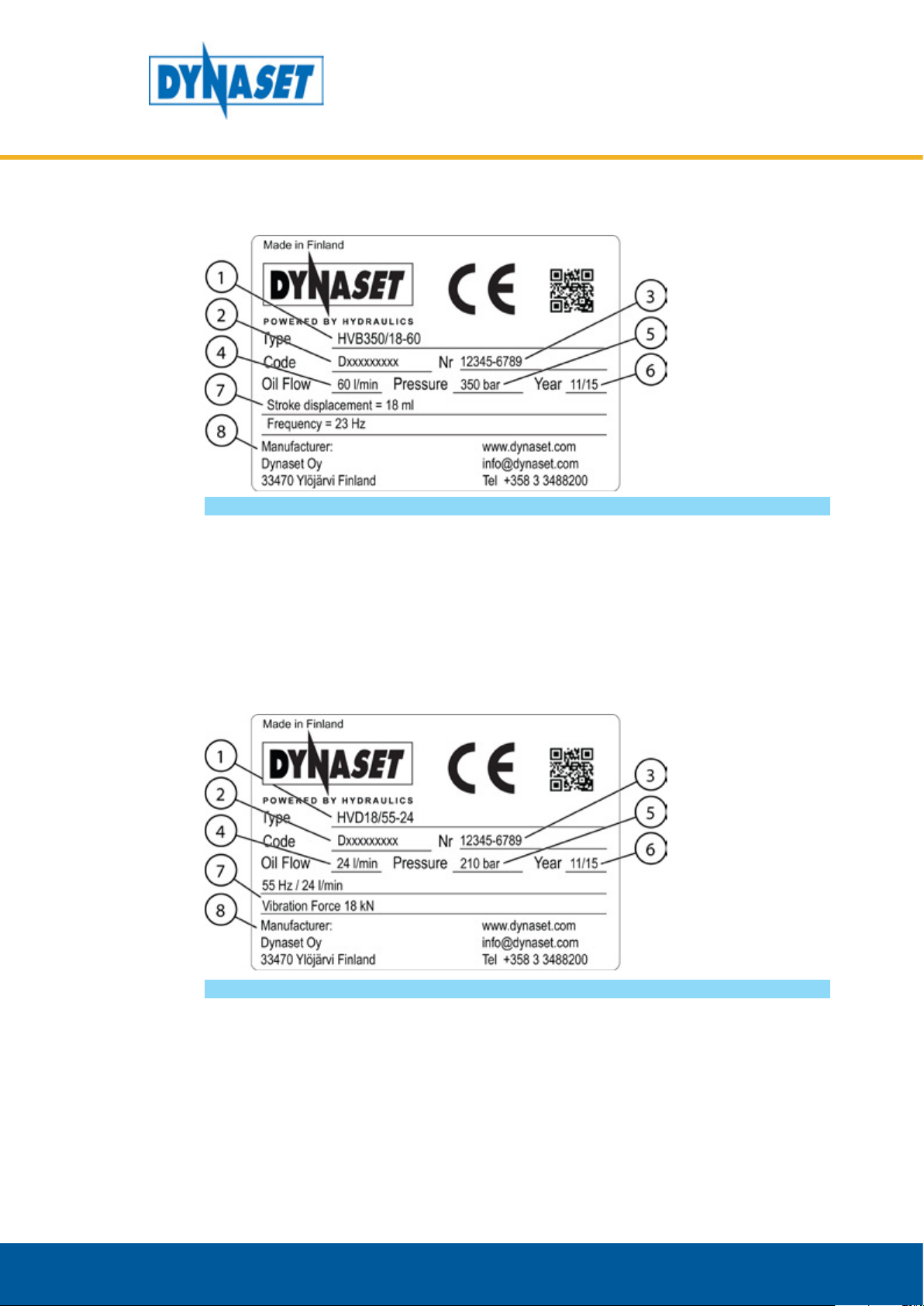
1.3. TYPE PLATE
Picture 3: HVB Type plate
The HVBs type plate shows the following information.
HYDRAULIC VIBRAS
GENERAL
1. Product identification key
2. Product code
3. Serial number
4. Maximum hydraulic flow
5. Maximum hydraulic pressure
Picture 4: HVD Type plate
6. Production month / year
7. Stroke displacement,
Vibration frequence at
max. hydraulic flow
8. Manufacturer’s contact
information
The HVDs type plate shows the following information.
1. Product identification key
2. Product code
3. Serial number
4. Maximum hydraulic flow
5. Maximum hydraulic pressure
Dynaset Oy | Menotie 3, 33470 Ylöjärvi | puh. 03 3488 200 | info@dynaset.com | www.dynaset.com
6. Production month / year
7. Vibration frequence
at max. hydraulic flow
and Vibration force
8. Manufacturer’s contact
information
11

1.4. HVB AND HVD LINE-UP
HYDRAULIC VIBRAS
GENERAL
Picture 5: HVB and HVD line-up
1. HVB 350 9-40
HVB 350 18-60
HVB 350 27-80
1.5. MAIN COMPONENTS OF HVB
2. HVD 18/55-24
3. HVD 70/35-100
12
Picture 6: Main components of HVB
1. Type plate
2. Serial number
3. Pressure line P
4. Return line T
5. Output A
Dynaset Oy | Menotie 3, 33470 Ylöjärvi | puh. 03 3488 200 | info@dynaset.com | www.dynaset.com
6. Output B
7. PT-flange
8. Head left
9. Head right

1.6. MAIN COMPONENTS OF HVD
HYDRAULIC VIBRAS
GENERAL
Picture 7: Main components of HVD
1. Type plate
2. Serial number
3. Pressure line P
4. Return line T
5. Head
Dynaset Oy | Menotie 3, 33470 Ylöjärvi | puh. 03 3488 200 | info@dynaset.com | www.dynaset.com
13

HYDRAULIC VIBRAS
GENERAL
14
Dynaset Oy | Menotie 3, 33470 Ylöjärvi | puh. 03 3488 200 | info@dynaset.com | www.dynaset.com
2. SAFETY
2.1. SAFETY PRECAUTIONS
ATTENTION!
Operators and maintenance personnel must always comply with local
safety regulations and precautions in order to close out the possibility of
damages and accidents.
The pressure in hydraulic circuit of HVB and HVD is considerably high. The technical
condition of your equipment and hydraulic system should be under constant
observation.
HYDRAULIC VIBRAS
SAFETY
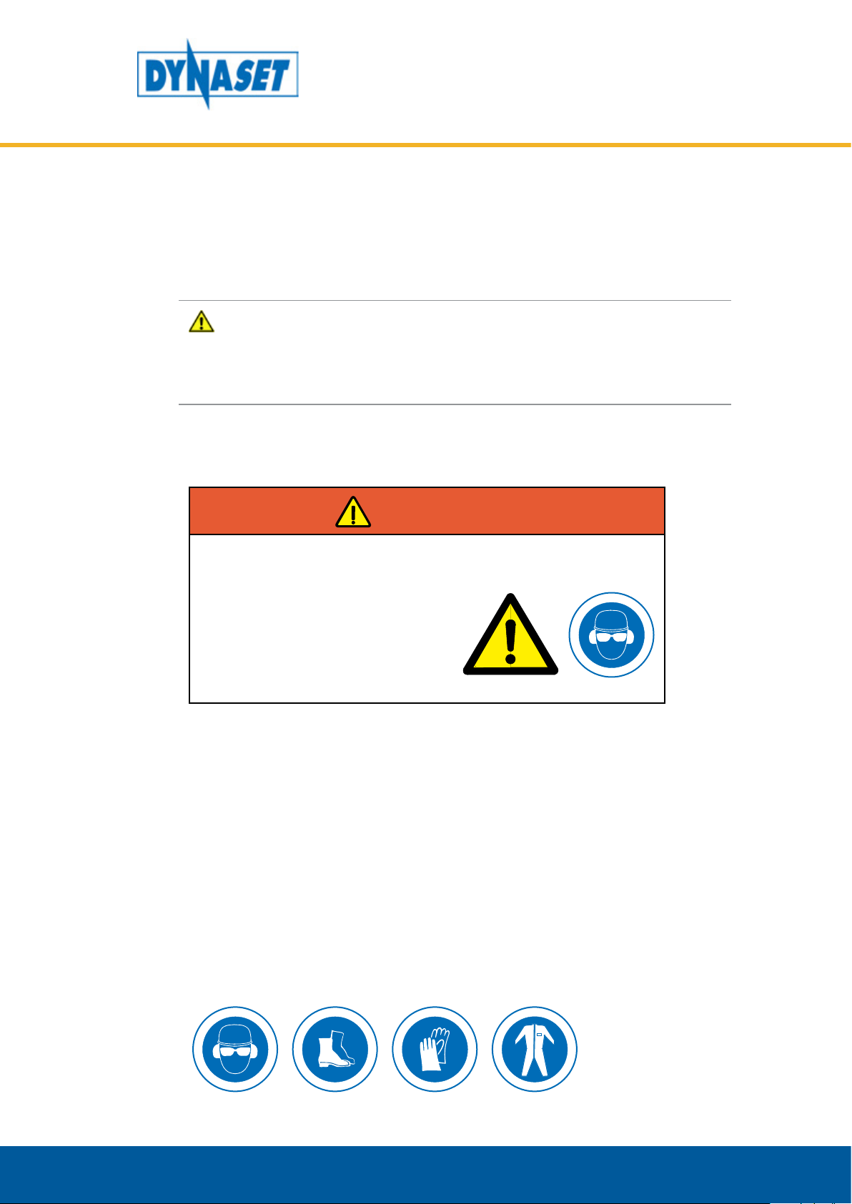
WARNING
HIGH PRESSURE OIL!
Can cause severe injuries.
Always wear appropriate clothing
and safety equipment.
Couplings, valves and hoses should be maintained tight and clean to avoid
possible leakages of pressure and hot blowouts. Hydraulic leakages must be
rectified immediately to avoid user and bystander injuries.
In order to avoid possible accidents, it is not allowed to clean or inspect HVB or
HVD unit when hydraulic circuit is pressurized. Prior to any cleaning, inspection
and service, hydraulic system of your base machine must be stopped and hydraulic
circuit must be depressurized.
2.2. SAFETY EQUIPMENT
Always wear appropriate clothing and safety equipment such as safety goggles,
safety shoes and ear protection when operating the HVB or HVD unit.
Dynaset Oy | Menotie 3, 33470 Ylöjärvi | puh. 03 3488 200 | info@dynaset.com | www.dynaset.com
15

2.3. OPERATING SAFETY
When operating the HVB or HVD unit, beware of machinery parts warmed by hot
hydraulic oil.
RISK OF BURNS!
Parts of the unit, oil, and oil filler cap
can be hotter than 80 °C!
Wear personal safety equipment!
HYDRAULIC VIBRAS
SAFETY
WARNING
ATTENTION!
Do not exceed the maximum pressure, temperature and load.
2.4. MAINTENANCE SAFETY
ATTENTION
Installation and service of hydraulic equipment must be performed by
qualified and experienced personnel only.
NOTE!
When carrying out any maintenance to HVB or HVD unit, keep the
components of the system clean. This is important to ensure safe, reliable
and longlife operation of your equipment.
16
Hydraulic system of a base machine should be maintained according to the service
program.
Dynaset Oy | Menotie 3, 33470 Ylöjärvi | puh. 03 3488 200 | info@dynaset.com | www.dynaset.com
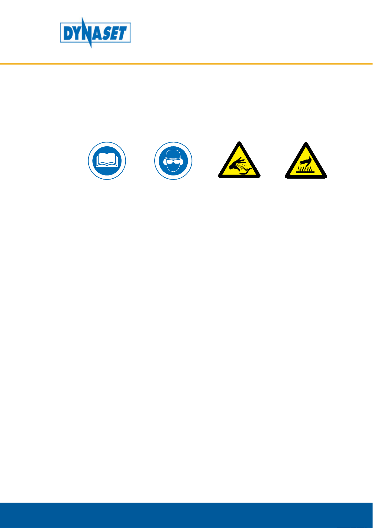
2.5. WARNING LABELS
JA SUOJALASEJA.
KÄYTTÖOHJEET.
VARO KUUMAA
Warning labels are included with each main product.
Product recipient is obligated to place warning labels on the DYNASET product.
Attach labels to visible and appropriate place onto or close to DYNASET product
where it’s easily seen. Clean surface with solvent detergent before attaching labels.
HYDRAULIC VIBRAS
SAFETY
LUE
KÄYTÄ
KUULONSUOJAIMIA
KORKEAPAINEINEN
ÖLJY.
PINTAA.
Dynaset Oy | Menotie 3, 33470 Ylöjärvi | puh. 03 3488 200 | info@dynaset.com | www.dynaset.com
17

HYDRAULIC VIBRAS
SAFETY
18
Dynaset Oy | Menotie 3, 33470 Ylöjärvi | puh. 03 3488 200 | info@dynaset.com | www.dynaset.com

3. OPERATING PRINCIPLES
3.1. OPERATING DESCRIPTION
HVB
HVB hydraulic Vibration Pump increases and decreases the pressure in cylinders A
and B lines creating a small fast pace movement, vibration.
HYDRAULIC VIBRAS
OPERATING INSTRUCTIONS
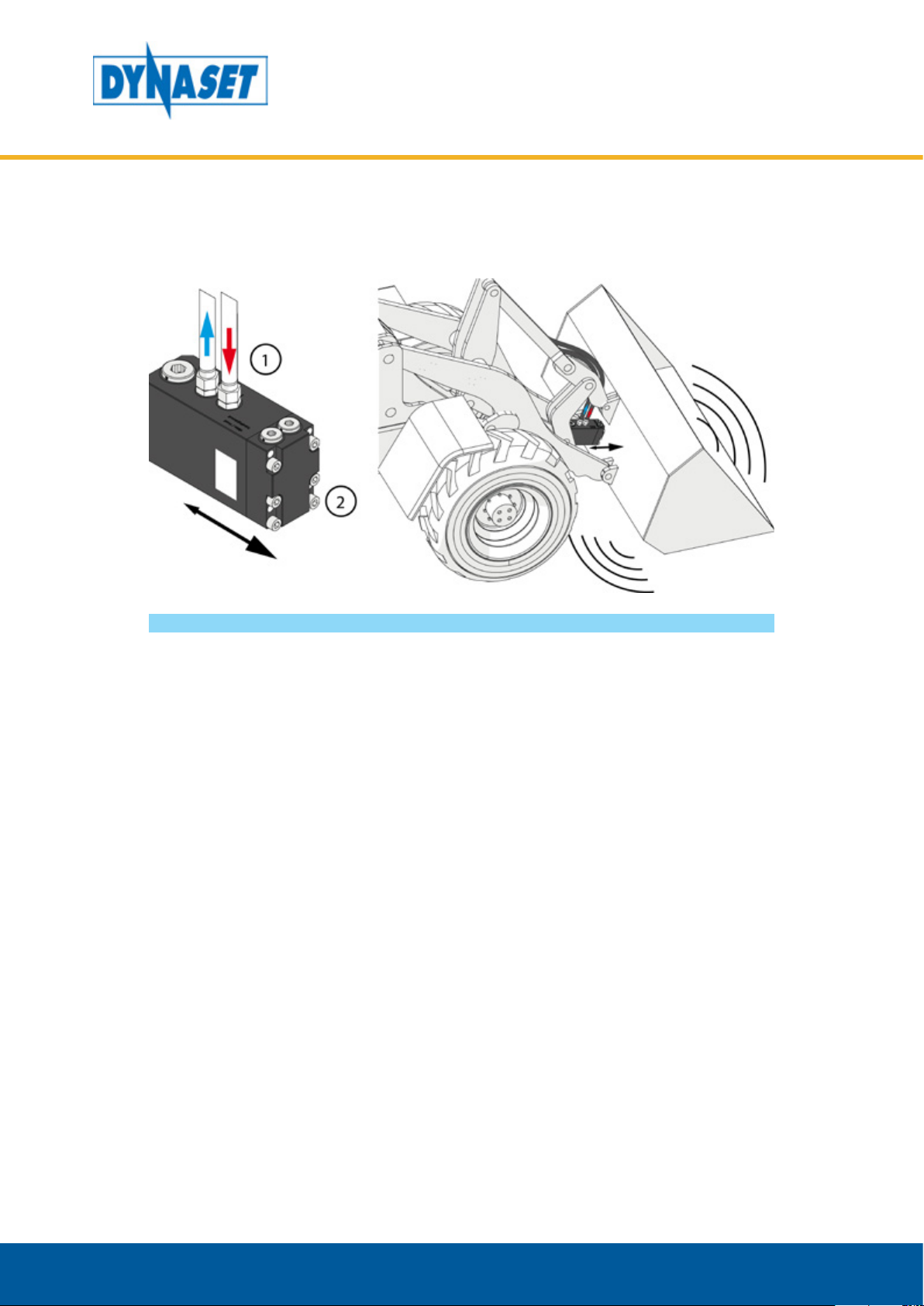
Picture 8: Operating description of HVB
When the hydraulic flow is opened to the HVB (1) it starts to create pressure to one
of the cylinders hydraulic lines. At the same time the HVB decreases the pressure
same amount from the other cylinders hydraulic line.
The patented pump structure of HVB reverses piston movement when the piston
reaches the peak point and the pressure direction turns to opposite. This way the
cylinder moves back and forth (2) safely creating vibration to the tool it is attached.
Dynaset Oy | Menotie 3, 33470 Ylöjärvi | puh. 03 3488 200 | info@dynaset.com | www.dynaset.com
19
HYDRAULIC VIBRAS
OPERATING INSTRUCTIONS
HVD
HVD Hydraulic directional vibra creates directional movement straight to the tool
e.g. bucket.
Picture 9: Operating description of HVD
When the hydraulic flow is opened to the HVD (1) the patented cylinder design
starts to move back and forth creating directional vibration to the tool (2).
20
Dynaset Oy | Menotie 3, 33470 Ylöjärvi | puh. 03 3488 200 | info@dynaset.com | www.dynaset.com
4. INSTALLATION
4.1. BEFORE INSTALLATION
ATTENTION!
Read these instructions before installation of the DYNASET product!
HYDRAULIC FLUIDS
HYDRAULIC VIBRAS
INSTALLATION
To use proper hydraulic fluid, READ CHAPTER “6.2. Hydraulic fluids”.
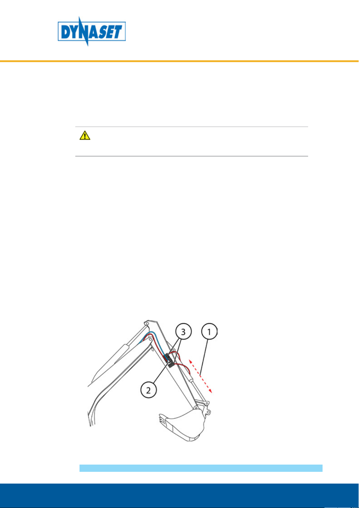
4.2. INSTALLATION OF HVB UNIT
The HVB unit is to be installed into the base machine’s existing hydraulic tool line
or build hydraulic lines to it.
1. HVB unit is installed parallel to the working cylinder as close as possible.
2. Connect the (P) pressure line and the (T) return line to the HVBs corresponding
places.
3. Connect the HVB pressure outlets to the cylinders hydraulic lines. The maximum
length for hydraulic hoses from HVB to cylinder is 1,5m (60 in).
Picture 10: HVB installation
Dynaset Oy | Menotie 3, 33470 Ylöjärvi | puh. 03 3488 200 | info@dynaset.com | www.dynaset.com
21

HYDRAULIC VIBRAS
INSTALLATION
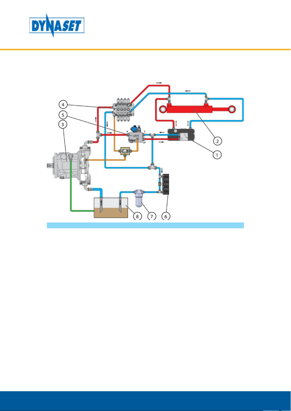
INSTALLING TO A BASE MACHINE WITH A EXISTING TOOL LINE
HVB can be installed to the excavator’s bucket boom to cylinder and take hydraulic
power from free tool line.
Picture 11: Installation of HVB to existing tool line
1. DYNASET HVB
2. Hydraulic tools cylinder
3. Base machine’s variable
displacement pump
4. Open centre directional
control valves
5. Oil cooler
6. Oil filter
7. Oil tank
22
Dynaset Oy | Menotie 3, 33470 Ylöjärvi | puh. 03 3488 200 | info@dynaset.com | www.dynaset.com

HYDRAULIC VIBRAS
INSTALLATION
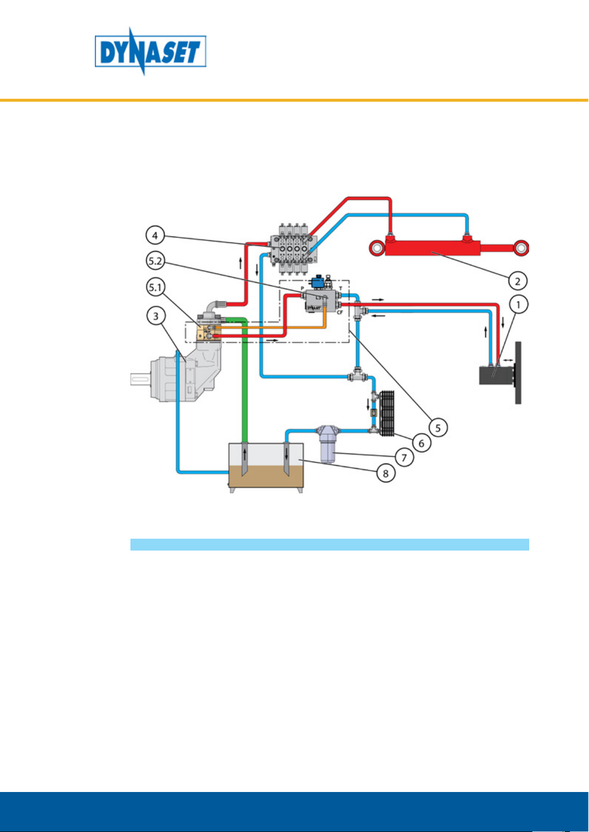
INSTALLING TO A BASE MACHINE WITHOUT EXISTING TOOL LINE
Base machines without hydraulic tool lines follow next schemas to install the HVB:
• In center open hydraulic system create hydraulic tool line using Dynaset PV‐SAE
priority valve.
4
5.2
5.1
3
P
LS
P
T
LS
CF
2
1
5
7 68
Picture 12: Installation of HVB with DYNASET PV-SAE priority valve
1. DYNASET HVB
2. Hydraulic tools cylinder
3. Base machine’s variable
displacement pump
4. Open centre directional
control valves
5. DYNASET Priority valve PV-SAE
Dynaset Oy | Menotie 3, 33470 Ylöjärvi | puh. 03 3488 200 | info@dynaset.com | www.dynaset.com
5.1. DYNASET PC-SAE
pressure compensator
5.2. DYNASET LSV Load
Sensing valve
6. Oil cooler
7. Oil filter
8. Oil tank
23
HYDRAULIC VIBRAS
INSTALLATION
• In close center hydraulic system use Dynaset LSV valve and LSV valve On/Off
switch to create the needed tool line.
Picture 13: Installation of HVB with DYNASET LSV valve and switch
1. DYNASET HVB
2. Hydraulic tools cylinder
3. Base machine’s variable
displacement pump
4. Closed centre directional
control valves
5. DYNASET LSV Load
Sensing valve
6. Oil cooler
7. Oil filter
8. Oil tank
24
Dynaset Oy | Menotie 3, 33470 Ylöjärvi | puh. 03 3488 200 | info@dynaset.com | www.dynaset.com

4.3. INSTALLATION OF HVD
The HVD unit can be installed into the base machine’s existing tool line or create a
hydraulic line for it using Dynaset PV-SAE.
GENERAL INSTALLATION
1. A) HVD is installed parallel and as close as possible to the working cylinder. B)
Install the HVD as center of the tool as possible.
HYDRAULIC VIBRAS
INSTALLATION
Picture 14: Installation position
2. Use the installation plate to install the HVD as shown in the picture below. Screw
first the Installation plate to the HVD (A). Recommended allen screws for HVD55
are 4 pcs 8.8 M10x80, tightening toque 45 Nm. Recommended allen screws for
HVD90 are 4 pcs 12.9 M14x90, tightening toque135 Nm.
3. Install the HVD to the tools surface. Recommended screws for HVD55 are 8.8
M10, tightening torque 45 Nm. Recommended screws for HVD90 are 12.9 M16,
tightening torque 300 Nm.
Picture 15: Installing HVD and installation plate
4. Connect the (P) pressure line and the (T) return line to the HVDs corresponding
places.
Dynaset Oy | Menotie 3, 33470 Ylöjärvi | puh. 03 3488 200 | info@dynaset.com | www.dynaset.com
25

HYDRAULIC VIBRAS
INSTALLATION
INSTALLING TO A BASE MACHINE WITH A EXISTING TOOL LINE
HVD can be installed to the free tool line.
Picture 16: Installation of HVD to existing tool line
1. DYNASET HVD
2. Hydraulic tools cylinder
3. Base machine’s variable
displacement pump
4. Open centre directional
control valves
5. Oil cooler
6. Oil filter
7. Oil tank
26
Dynaset Oy | Menotie 3, 33470 Ylöjärvi | puh. 03 3488 200 | info@dynaset.com | www.dynaset.com
HYDRAULIC VIBRAS
INSTALLATION
INSTALLING TO A BASE MACHINE WITHOUT EXISTING TOOL LINE
Base machines without hydraulic tool lines follow next schemas to install the HVD:
• In center open hydraulic system create hydraulic tool line using Dynaset PV‐SAE
priority valve.
Picture 17: Installation of HVD with DYNASET PV-SAE priority valve
1. DYNASET HVD
2. Hydraulic tools cylinder
3. Base machine’s variable
displacement pump
4. Open centre directional
control valves
5. DYNASET Priority valve PV-SAE
Dynaset Oy | Menotie 3, 33470 Ylöjärvi | puh. 03 3488 200 | info@dynaset.com | www.dynaset.com
5.1. DYNASET PC-SAE
pressure compensator
5.2. DYNASET LSV Load
Sensing valve
6. Oil cooler
7. Oil filter
8. Oil tank
27

HYDRAULIC VIBRAS
INSTALLATION
• In close center hydraulic system use Dynaset LSV valve and LSV valve On/Off
switch to create the needed tool line.
Picture 18: Installation of HVD with DYNASET LSV valve and switch
1. DYNASET HVD
2. Hydraulic tools cylinder
3. Base machine’s variable
displacement pump
4. Closed centre directional
control valves
5. DYNASET LSV Load
Sensing valve
6. Oil cooler
7. Oil filter
8. Oil tank
28
Dynaset Oy | Menotie 3, 33470 Ylöjärvi | puh. 03 3488 200 | info@dynaset.com | www.dynaset.com

4.4. ELECTRIC CONNECTIONS
If you order the HVB or HVD with DYNASET LSV or PV-SAE valve the connection of
the solenoid valve is to be made according to the following schema.
Picture 19: Electric schema for solenoid valve
HYDRAULIC VIBRAS
INSTALLATION
Dynaset Oy | Menotie 3, 33470 Ylöjärvi | puh. 03 3488 200 | info@dynaset.com | www.dynaset.com
29

HYDRAULIC VIBRAS
INSTALLATION
30
Dynaset Oy | Menotie 3, 33470 Ylöjärvi | puh. 03 3488 200 | info@dynaset.com | www.dynaset.com

5. OPERATION
After having ensured the proper mechanical and hydraulic installation of the HVB
or HVD unit it is ready for use.
5.1. OPERATING HVB AND HVD UNITS
HVB and HVD units are typically controlled with a push button from the cabin.
1. Start the base machine and make sure the hydraulic system is operational
2. After system is operational the vibration is strated by pressing the activation
button. Vibration starts immediately
If HVD is installed as in picture 16 on page 26, vibras pressure line is installed in to
same pressure line with the tools cylinder, the HVD starts automatically when the
pressure has increased enough in the pressure line.
HYDRAULIC VIBRAS
OPERATION
This might happen when e.g. a bucket is used to penetrate frozen ground. When
the bucket hits frozen spot on the ground and can’t penetrate the pressure rises
and the HVD starts to vibrate helping the bucket to get through. The vibration
stops when the bucket pierces the ground and pressure decreases in the cylinder.
Picture 20: Operating HVB and HVD units
Dynaset Oy | Menotie 3, 33470 Ylöjärvi | puh. 03 3488 200 | info@dynaset.com | www.dynaset.com
31

HYDRAULIC VIBRAS
OPERATION
32
Dynaset Oy | Menotie 3, 33470 Ylöjärvi | puh. 03 3488 200 | info@dynaset.com | www.dynaset.com
6. MAINTENANCE
DYNASET HVB and HVD units are low-maintenance units. Only normally wearing
parts and materials should be replaced either when necessary or in accordance
with a service program.
Prior to starting any maintenance or repair, ensure that the HVB or HVD unit is
completely depressurized.
6.1. MAINTENANCE INTERVAL
All maintenance must be complied with as they are scheduled in this manual.
The following table provides maintenance schedule for DYNASET HVB or HVD unit.
HYDRAULIC VIBRAS
MAINTENANCE
CHECK POINTS
Clean HVB / HVD unit x
Change sealings and pump uid valves x
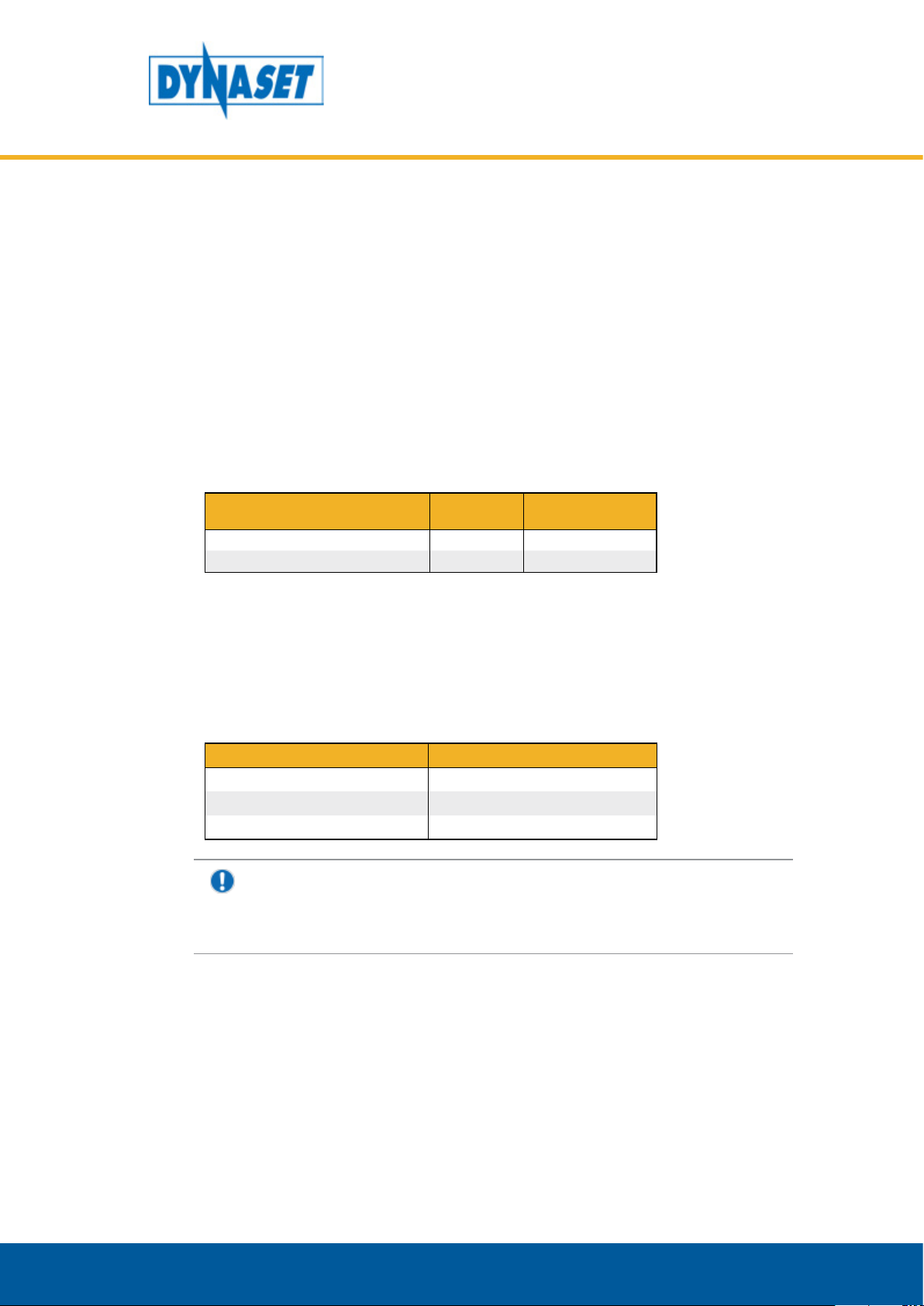
6.2. HYDRAULIC FLUIDS
Wide range of standard hydraulic fluids can be used with DYNASET hydraulic
equipment. Depending on the operating temperature, following mineral hydraulic
oils are recommended:
Mineral hydraulic oil Operation temperature up to
ISO VG 32S 60 °C
ISO VG 46S 70 °C
ISO VG 68S 80 °C
NOTE!
Recommended oil viscosity is between 10 to 35 cSt when operating at
normal operating temperature.
After daily use Every 4000 hours or if
necessary
Synthetic and bio-oils can also be used if their viscosity characteristics and
lubricating efficiency are similar to the mineral oils.
Automatic transmission fluids and even engine oils can be used, provided that
they are allowed to be used in hydraulic system of your base machine.
For the hydraulic fluid change interval follow the base machine’s maintenance
instructions.
To use special hydraulic fluids with DYNASET equipment, please contact the
nearest DYNASET representative for more information.
Dynaset Oy | Menotie 3, 33470 Ylöjärvi | puh. 03 3488 200 | info@dynaset.com | www.dynaset.com
33
6.3. CLEANING THE HVB AND HVD UNITS
ATTENTION!
Keep the HVB and HVD units clean to enable its safe and longlife
operation. Check and clean your HVB and HVD units after every work shift.
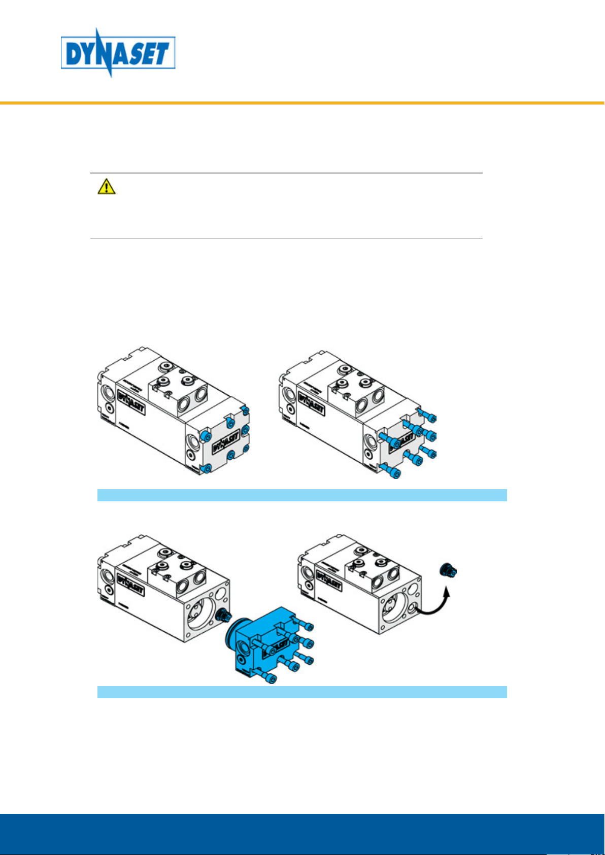
6.4. REPLACING SEALS AND INTAKE VALVES TO HVB
1. Remove screws from the head.
HYDRAULIC VIBRAS
MAINTENANCE
Picture 21: Removing the pump head
2. Pull out the head and remove used intake valve. Repeat the 1.-2. phase to the
other head.
Picture 22: Removing the pump head and intake valve
34
Dynaset Oy | Menotie 3, 33470 Ylöjärvi | puh. 03 3488 200 | info@dynaset.com | www.dynaset.com
HYDRAULIC VIBRAS
MAINTENANCE
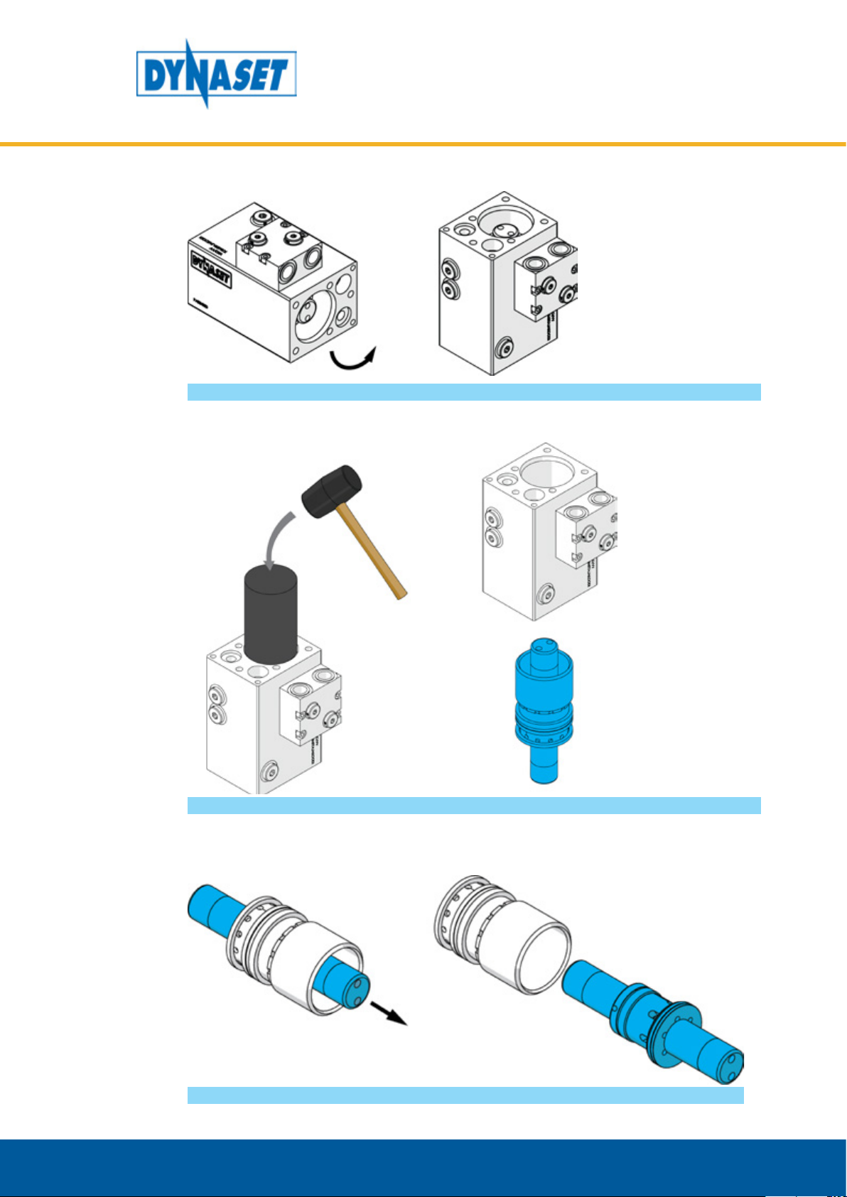
3. Turn the pump frame into a vertical position.
Picture 23: Positioning the body
4. Use rubber hammer and special tool to remove piston assembly with cylinder
and sealing flanges from the pump.
Picture 24: Removing the piston
5. Remove the piston assembly from the cylinder.
Picture 25: Removing the piston from the cylider
Dynaset Oy | Menotie 3, 33470 Ylöjärvi | puh. 03 3488 200 | info@dynaset.com | www.dynaset.com
35

HYDRAULIC VIBRAS
MAINTENANCE
6. Remove seals from the piston assembly and from the cylinder.
Picture 26: Removing seals from piston and the cylinder
7. Install new seals to the piston assembly.
Picture 27: Installing the seals to piston and the cylinder
8. Install the piston assembly to the cylinder. Use vaseline or mineral oil on the seal
and mating surfaces to make installation easy.
Picture 28: Lubricating the piston and the cylinder
36
Dynaset Oy | Menotie 3, 33470 Ylöjärvi | puh. 03 3488 200 | info@dynaset.com | www.dynaset.com

HYDRAULIC VIBRAS
MAINTENANCE
9. Lubricate mating surfaces of the piston assembly and insert it to the body. Place
the special tool in the top of the piston assembly.
Picture 29: Installing the piston assembly to the pump body 1
NOTE!
Make sure that the piston assembly is installed correctly.
10. Use rubber hammer to install piston assembly into the body.
Picture 30: Installing the piston assembly to the pump body 2
Dynaset Oy | Menotie 3, 33470 Ylöjärvi | puh. 03 3488 200 | info@dynaset.com | www.dynaset.com
37

HYDRAULIC VIBRAS
MAINTENANCE
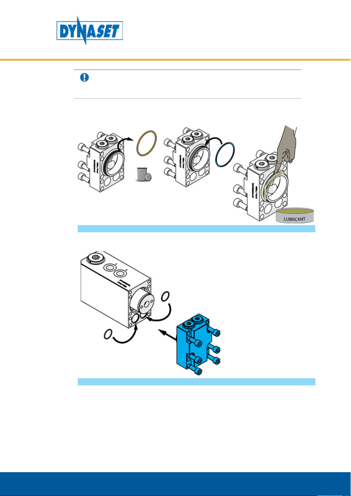
11. Remove seals from the head and install new seals. Repeat for both heads.
Picture 31: Removing the pump head seals
NOTE!
DYNASET recommends replacing the pumping fluid valves at the same
time as the pump seals. READ CHAPTER ”6.4. Replacing seals and intake
valves to HVB”
12. Install intake valve and head into the body. Repeat for both heads. Read correct
bolt torques from chapter 6.6
38
Picture 32: Installing the pump heads
Dynaset Oy | Menotie 3, 33470 Ylöjärvi | puh. 03 3488 200 | info@dynaset.com | www.dynaset.com
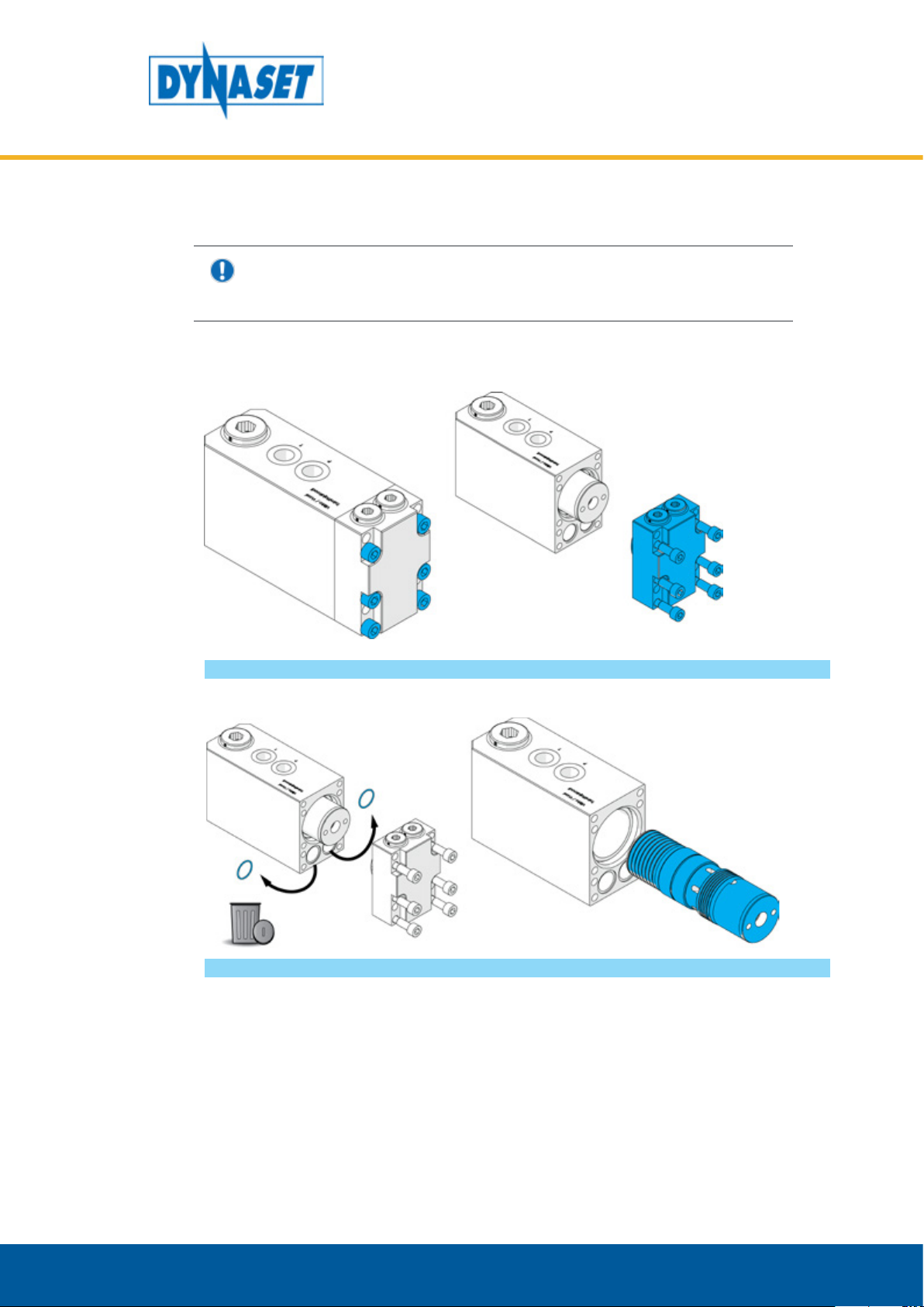
6.5. REPLACING SEALS AND INTAKE VALVES TO HVD
NOTE!
Use treadlocker when tightening the screws back on the HVD.
1. Open screws to remove the head.
HYDRAULIC VIBRAS
MAINTENANCE
Picture 33: Removing the pump head
2. Remove used old seals and pull out the piston assembly.
Picture 34: Removing the body seals and the piston
Dynaset Oy | Menotie 3, 33470 Ylöjärvi | puh. 03 3488 200 | info@dynaset.com | www.dynaset.com
39
HYDRAULIC VIBRAS
MAINTENANCE
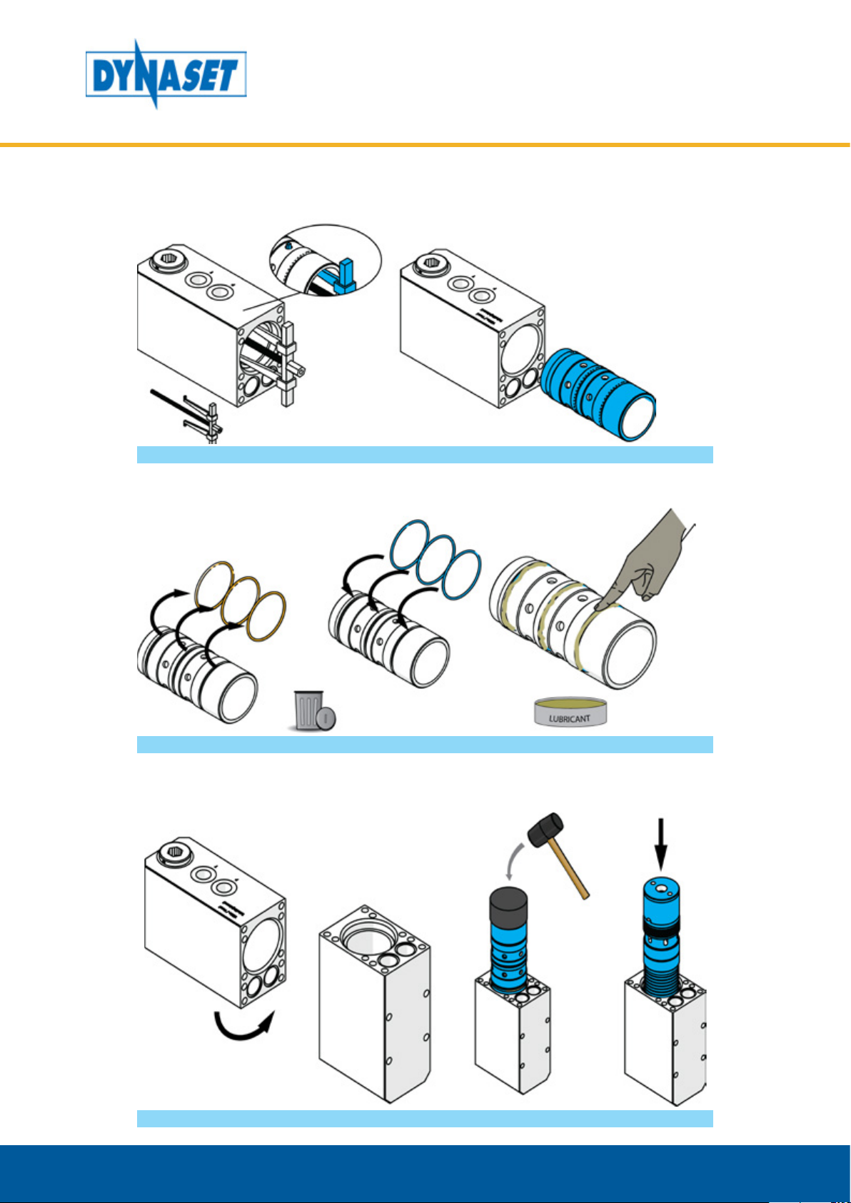
3. Remove the piston shell using extractor. Insert the extractors pins to the holes in
cylinder shell. The holes are, depending on the model, at least 8 mm in diameter.
Picture 35: Removing piston shell
4. Replace the old seals from the piston assembly and lubricate them with grease.
Picture 36: Replacing and lubricating piston assembly seals
5. Turn the HVD body vertical and use rubber hammer and special tool to install
piston shell into cylinder. Then install the piston.
40
Picture 37: Installing piston
Dynaset Oy | Menotie 3, 33470 Ylöjärvi | puh. 03 3488 200 | info@dynaset.com | www.dynaset.com
HYDRAULIC VIBRAS
NOTE!
Make sure that the piston assembly is installed correct way
6. Replace the seal from the head assembly and lubricate it.
MAINTENANCE
Picture 38: Replacing and lubricating head seals
7. Install new seals into the body and install the head.
Picture 39: Installing body seals and head
Dynaset Oy | Menotie 3, 33470 Ylöjärvi | puh. 03 3488 200 | info@dynaset.com | www.dynaset.com
41

HYDRAULIC VIBRAS
MAINTENANCE
8. Tighten the screws into correct torque. Read bolt torque values from 6.6
Picture 40: Tightening the screws
6.6. BOLT TIGHTENING TORQUES
BOLT TIGHTENING TORQUE
M6 8.8 9 Nm
M8 8.8 22 Nm
M10 8.8 45 Nm
M10 12.9 75 Nm
M12 8.8 75 Nm
M14 12.9 210 Nm
M16 8.8 180 Nm
M16 12.9 300 Nm
42
Dynaset Oy | Menotie 3, 33470 Ylöjärvi | puh. 03 3488 200 | info@dynaset.com | www.dynaset.com
6.7. TROUBLESHOOTING
Performing the maintenance tasks requires a qualified hydraulic mechanic.
Please, contact DYNASET authorized workshop or dealer for more maintenance
information.
FAILURE REASON CORRECTIVE ACTION
HYDRAULIC VIBRAS
MAINTENANCE
Hydraulic ow not
sucient or no hydraulic
ow at all.
Hydraulic pressure too low. Adjust the hydraulic pressure.
Enable or adjust the hydraulic
ow.
HVB / HVD does not work.
HVB works, but does not
deliver output ow.
Sealings and secondary
pistons wear o repeatedly.
Leakages.
Hydraulic ow reversed.
Hydraulic piston damaged
mechanically.
Intake valves are open
(jammed with debris) or
damaged.
Broken lter in hydraulic
system.
Filter missing totally in
hydraulic system.
Hydraulic oil leakages.
Check and reconnect hydraulic
hoses. Pressure hose should be
connected to P-port and return
hose to T-port.
Replace damaged part.
Check secondary valves and clean
them thoroughly or replace when
damaged.
Check and replace lter and worno parts
Install lter. Always must use lter.
Check the tightness of component
mating, tighten screws.
Replace sealings of pumps mated
surfaces if necessary.
Check and tighten ttings.
Replace if necessary.
Check the tightness of component
mating, tighten screws.
Pumping uid leakages.
Dynaset Oy | Menotie 3, 33470 Ylöjärvi | puh. 03 3488 200 | info@dynaset.com | www.dynaset.com
Replace sealings of pumps mated
surfaces if necessary.
Check and tighten couplings.
Replace if necessary.
43

HYDRAULIC VIBRAS
MAINTENANCE
44
Dynaset Oy | Menotie 3, 33470 Ylöjärvi | puh. 03 3488 200 | info@dynaset.com | www.dynaset.com

7. MANUFACTURER’S LIMITED WARRANTY
1. Warranty coverage
All hydraulic accessories manufactured by DYNASET OY are subject to the terms
and conditions of this limited warranty. Products are warranted to the original
purchaser to be free from defects in materials or workmanship. Exclusions from
warranty are explained in item Exclusions from warranty.
2. Beginning of warranty period
Warranty period begins from the delivery date of the product. Delivery is
considered to be done on the date when installation has been accomplished or
purchaser has taken the product in use. Product is considered as taken in use at the
date when DYNASET OY has delivered the product to purchaser, unless separately
agreed otherwise by written agreement.
3. Warranty period
Warranty period is twenty four (24) months based on maximum of 2000 hours
usage during this time period. In cases where the system is provided complete with
certain special components (e.g. drive unit), those components are considered as
a subject to their manufacturer’s warranty.
HYDRAULIC VIBRAS
WARRANTY
4. Warranty procedures
Immediately upon identifying a problem which purchaser believes to be a failure
subject to the product’s limited warranty, purchaser must contact primary to the
seller of the product. Contact must be made as soon as possible, latest thirty (30)
days after the problem was identified. Seller and/or manufacturer technical staff
determines the nature of the problem primarily by phone or e-mail. Purchaser
commits to give necessary information and to perform routine diagnostic
procedures in order to determine the nature of the problem and necessary
procedures.
5. Warranty repairs
If the product is found to be defective during the warranty period, DYNASET
OY will, at its option, either repair the product, author it to be repaired at its
authorized workshop or exchange the defective product. If the product must be
repaired elsewhere than premises of DYNASET OY or authorized workshop, all
costs excluded from this warranty (traveling and waiting hours, daily allowance,
traveling expenses and uninstallation/reinstallation costs) will be charged from
the purchaser.
If the problem is not covered by this limited warranty, DYNASET OY has the right
to charge purchaser of troubleshooting and repairing.
6. Delivery terms of warranty repair
If the product is found possible to be defective under this limited warranty and it
needs to be repaired, DYNASET OY gives Warranty Return Number (WRN). Items
being returned must be shipped, at the purchaser’s cost, adequately packed for
shipment, to the DYNASET OY or to other location authored by DYNASET OY.
Shipment documents must contain:
Purchaser’s name and contact information
Receipt of original purchase
WRN code
Problem description
7. Warranty of repaired product
Warranty period of the product repaired under this limited warranty continues to
Dynaset Oy | Menotie 3, 33470 Ylöjärvi | puh. 03 3488 200 | info@dynaset.com | www.dynaset.com
45

HYDRAULIC VIBRAS
WARRANTY
the end of original warranty period.
8. Exclusions from warranty
This warranty shall not apply to:
• Failures due to normal wear and tear, improper installation, misuse, abuse,
negligence, purchaser selection of improper product to intended use, accident,
improper filtration of hydraulic oil or intake water or lack of maintenance.
• Cost of maintenance, adjustments, installation or startup.
• Coating, hydraulic oil, quick couplings and interconnection hoses (internal or
external to system assemblies).
• Products altered or modified in a manner not authorized by DYNASET OY in
writing.
• Products which have been repaired during warranty period by others than
DYNASET OY or its authorized workshop.
• Costs of any other damage or loss, whether direct, indirect, incidental, special
or consequential, arising out of the use of, or the inability to use, the product.
• Telephone or other communications expense.
• Product that is used in exceptional conditions, considered to cause excessive
wear and tear.
• Faults caused by nature phenomenon’s like flood, thunder, etc.
© DYNASET OY, all rights reserved
46
Dynaset Oy | Menotie 3, 33470 Ylöjärvi | puh. 03 3488 200 | info@dynaset.com | www.dynaset.com

8. PRODUCT DISPOSAL
Dispose and recycle all DYNASET products and their packaging environmentally
responsible way.
Do not dispose used oils, electrical components, batteries or any other hazardous
waste with normal waste. They are harmful for the environment and can be
recycled for re-use.
Contact your local waste recycling facility for more information about recycling
hazardous waste.
NOTE!
Always act according to the waste legislation, regulations and
recommendations in waste disposal and waste recycling issued by your
local authorities.
HYDRAULIC VIBRAS
PRODUCT DISPOSAL
Dynaset Oy | Menotie 3, 33470 Ylöjärvi | puh. 03 3488 200 | info@dynaset.com | www.dynaset.com
47

HYDRAULIC VIBRAS
PRODUCT DISPOSAL
48
Dynaset Oy | Menotie 3, 33470 Ylöjärvi | puh. 03 3488 200 | info@dynaset.com | www.dynaset.com

DECLARATION OF CONFORMITY
9. DECLARATION OF CONFORMITY
We hereby declare that the design and manufacture of the products stated below
are in conformity with the provisions of the European Parliament and Councils on
the harmonization of the laws of Member States on the safety of machines.
Machine directive 2006/42/EC
Applied conformity standards:
CEN EN ISO 4413: EN ISO 4413:2010 Hydraulic fluid power -
General rules and safety requirements for systems and their
components.
HYDRAULIC VIBRAS
Manufacturer: DYNASET Oy
Menotie 3, FI-33470 Ylöjärvi, Finland
Product group: HYDRAULIC VIBRAS
Products: HVB Hydraulic vibration pump,
HVD Hydraulic directional vibra
If the device has been modified by someone other than the manufacturer or
without the manufacturer’s permission, this declaration is not valid.
Timo Nieminen
R&D Manager
Ylöjärvi, Finland 20.4.2016
Dynaset Oy | Menotie 3, 33470 Ylöjärvi | puh. 03 3488 200 | info@dynaset.com | www.dynaset.com
49

HYDRAULIC VIBRAS
DECLARATION OF CONFORMITY
50
Dynaset Oy | Menotie 3, 33470 Ylöjärvi | puh. 03 3488 200 | info@dynaset.com | www.dynaset.com

10. TECHNICAL SPECIFICATIONS
HYDRAULIC VIBRAS
TECHNICAL SPECIFICATIONS
HVB 350
9-40
OUTPUT CHARACTERISTICS
Vibration force max. kN -
Frequency Hz 30 23 19 55 35
HYDRAULIC CONNECTIONS
Pressure Line P BSP 1/2” BSP 1/2” BSP 1/2” BSP 1/2” BSP 1”
Return line T BSP 1/2” BSP 1/2” BSP 1/2” BSP 1/2” BSP 1”
Outlet A / B BSP 1/2” BSP 1/2” BSP 1/2” - -
HYDRAULIC POWER REQUIREMENTS
Flow max. l/min
Pressure max. bar (psi) 350 (5076) 350 (5076) 350 (5076) 210 (3046) 210 (3046)
HYDRAULIC FLUID REQUIREMENTS
Viscocity cSt 100-200 / optimum 25-35
Temperature * ° C (° F) max. 70 (160)
Filter ratio μm 25 or better
OVERALL DIMENSIONS
Length mm (in) 253 (10) 253 (10) 253 (10) 225 (8.9) 278 (11.0)
Width mm (in) 115 (4.5) 115 (4.5) 115 (4.5) 80 (3.1) 135 (5.3)
Height mm (in) 130 (5.1) 130 (5.1) 130 (5.1) 122 (4.8) 183 (7.2)
Weight kg (lbs)
Base machine size t (U.S. t) 0 - 5 (0-11) 4-10 (8.8-22) 7 - 20 (15.4-44) - -
Gallons are U.S. liquid gallons
* READ CHAPTER ”6.2. Hydraulic uids”
(gpm) 40 (10.6) 60 (15.8) 80 (21.1) 24 (6.3) 100 (26.4)
13 (29) 13 (29) 13 (29) 13 (29) 40 (88)
HVB 350
18-60
- -
HVB 350
27-80
HVD 18
55-24
18
HVD 70
35-100
70
Dynaset Oy | Menotie 3, 33470 Ylöjärvi | puh. 03 3488 200 | info@dynaset.com | www.dynaset.com
51

HYDRAULIC VIBRAS
TECHNICAL SPECIFICATIONS
52
Dynaset Oy | Menotie 3, 33470 Ylöjärvi | puh. 03 3488 200 | info@dynaset.com | www.dynaset.com

© DYNASET OY, all rights reserved

Menotie 3
FI-33470 Ylöjärvi, Finland
tel: +358 3 3488 200
info@DYNASET.com
ELECTRICITY
HG Hydraulic Generator
HGV POWER BOX Variable Hydraulic Generator System
HGV Variable Hydraulic Generator System
HWG Hydraulic Welding Generator
HGG Hydraulic Ground Power Generator
HIGH PRESSURE WATER
HPW Hydraulic High Pressure Water Pump
HPW Hydraulic Power Washer
KPL High Pressure Street Washing Unit
HPW-DUST High Pressure Dust Suppression System
PPL High Pressure Pipe Cleaning Unit
HPW-FIRE High Pressure Fireghting System
FP Fire Fighting Piercing Kit
HDF Hydraulic Drilling Fluid Pump
JPL High Pressure Bin Washing System
HSP Hydraulic Submersible Pump
MAGNET POWER
HMG PRO Hydraulic Magnet Generator
MAG Lift Magnet
HMAG PRO Hydraulic Magnet
VIBRATION
HVB Hydraulic Vibration Pump
HVD Hydraulic Directional Vibra
HVC Hydraulic Vibration Compactor
HRC Hydraulic Reversal Cylinder
POWER BOOSTING
HPI Hydraulic Pressure Intensier
HPI-C Hydraulic Pressure Intensier for Cylinder
COMPRESSED AIR
HK Hydraulic Piston Compressor
HKL Hydraulic Rotary Vane Compressor
HKR Hydraulic Screw Compressor
www.DYNASET.com
KNOW-HOW
Hydraulic Power Take-o (PTO)
Hydraulic Power Unit Technology
HEU Hydraulic Expansion Unit
HRU Hydraulic Rescue Unis
De-Icing Technology
Installation Valves
HHK Hydraulic Grinder
HV/HVY Hydraulic Winch / Winch Unit
 Loading...