


USER MANUAL
06/18
rev 1.2
HYDRAULIC ROTARY VANE COMPRESSORS
HKL 400
HKL 801
Download PDF version from www.Dynaset.com/manuals Keycode: LZ4BYM
HKL 1300
HKL 1800
HKL 2600
HKL 4100
HKL 5000
HKL 7500


Congratulations!
You have just purchased DYNASET hydraulic equipment!
The equipment allows you to maximize the productivity and
efficiency of your mobile machine. Read this User Manual
before using your new equipment. It contains important
information that will help you to take the full advance of the
technical features avaible in your equipment.
Please contact us for any feedback you might have on our
products. Your feedback is important to us for improving our
products and customer service.
We are constantly developing and releasing new innovations.
Please visit on our website and social media channels for the
latest news and updates.
www.dynaset.com
info@dynaset.com
www.facebook.com/dynaset
www.youtube.com/dynasetoy
www.twitter.com/Dynaset_ofcl
www.instagram.com/dynaset_official
Subscribe to our newsletter. Follow the QR
code!
Dynaset Oy | Menotie 3, FI-33470 Ylöjärvi, Finland | tel: +358 3 3488 200 | info@dynaset.com | www.dynaset.com
3

HYDRAULIC ROTARY VANE COMPRESSORS
TABLE OF CONTENTS
1. GENERAL 7
1.1. PRODUCT INFORMATION 7
1.2. PRODUCT IDENTIFICATION KEY 7
1.3. TYPE PLATE 9
1.4. HKL COMPRESSOR LINEUP 10
1.5. MAIN COMPONENTS OF HKL COMPRESSOR 11
2. SAFETY 13
2.1. SAFETY PRECAUTIONS 13
2.2. SAFETY EQUIPMENT 13
2.3. OPERATING SAFETY 14
2.4. MAINTENANCE SAFETY 15
2.5. WARNING LABELS 15
3. OPERATING PRINCIPLES 17
3.1. OPERATING DESCRIPTION 17
3.2. AUTOMATIC RPMCONTROL 20
3.3. LUBRICATION SYSTEM OF COMPRESSOR 20
3.4. PRESSURE AND COMPRESSION RATIO 20
3.5. PNEUMATICELECTRIC OFFLOAD VALVE 21
3.6. TEMPERATURE SWITCH 22
3.7. HYDRAULIC DIAGRAM 23
4. INSTALLATION 25
4.1. BEFORE INSTALLATION 25
4.1.1. HYDRAULIC SYSTEM OF A BASE MACHINE 25
4.1.2. DYNASET VALVES
32
4.2. INSTALLING DYNASET HYDRAULIC PRODUCT 33
4.2.1. PLACING DYNASET HYDRAULIC PRODUCT 33
4.2.2. INSTALLING DYNASET VALVES
4.2.3. CONNECTING HYDRAULIC HOSES
4.2.4. HYDRAULIC FLUIDS
35
33
33
4.3. INSTALLING HKL COMPRESSOR 35
4.3.1. MAXIMUM INCLINATIONS 35
4.3.2. CONNECTION TO THE AIR SUPPLY SYSTEM
Dynaset Oy | Menotie 3, 33470 Ylöjärvi | puh. 03 3488 200 | info@dynaset.com | www.dynaset.com
36

HYDRAULIC ROTARY VANE COMPRESSORS
TABLE OF CONTENTS
5. OPERATION 37
5.1. BEFORE STARTING THE COMPRESSOR 37
5.2. STARTING THE COMPRESSOR 38
5.3. AIR AND OIL TEMPERATURES 39
5.4. AIR HUMIDITY 40
5.5. COLD STARTS 41
5.6. OFFLOAD MODE 41
5.7. STOPPING THE COMPRESSOR 41
6. MAINTENANCE 43
6.1. MAINTENANCE INTERVALS 44
6.2. HYDRAULIC FLUIDS 44
6.3. COMPRESSOR OILS 45
6.4. CLEANING THE COMPRESSOR 46
6.5. OIL LEVEL CHECK 46
6.6. OIL UALITY CHECK 49
6.7. OIL AND OIL FILTER REPLACEMENT 49
6.8. OIL RETURN VALVES REPLACEMENT 52
6.9. AIROIL SEPARATING ELEMENT REPLACEMENT 53
6.10. REPLACING THE AIR FILTER ELEMENT 56
6.11. ADJUST THE OFFLOAD PRESSURE 57
6.11.1. ADJUSTING THE OFFLOAD PRESSURE IN STANDARD COMPRESSOR 58
6.11.2. ADJUSTING THE OFFLOAD PRESSURE IN OPE COMPRESSOR
58
6.12. TROUBLESHOOTING 63
7. MANUFACTURER’S LIMITED WARRANTY 65
8. PRODUCT DISPOSAL 67
9. DECLARATION OF CONFORMITY 69
10. TECHNICAL SPECIFICATIONS 71
Dynaset Oy | Menotie 3, 33470 Ylöjärvi | puh. 03 3488 200 | info@dynaset.com | www.dynaset.com

HYDRAULIC ROTARY VANE COMPRESSORS
TABLE OF PICTURES
Picture 1: Identication key for HKL .................................................................................................................................7
Picture 2: Type plate ......................................................................................................................................................... 9
Picture 3: HKL compressor line-up .................................................................................................................................10
Picture 4: Main components of HKL compressor ............................................................................................................. 11
Picture 5: Operating description: Air intake .................................................................................................................... 17
Picture 6: Operating description: Air compression and oil ltering ................................................................................. 18
Picture 7: Operating description: Oil cooling ..................................................................................................................19
Picture 8: The nominal discharge of HKL compressor ......................................................................................................19
Picture 9: Automatic RPM-control .................................................................................................................................. 20
Picture 10: Pneumatic-electric o-load valve location ................................................................................................... 21
Picture 11: Temperature switch ...................................................................................................................................... 22
Picture 12: Open centre hydraulic system with Load Sensing variable displacement pump ........................................... 26
Picture 13: Connection gure for open centre hydraulic system with Load Sensing variable displacement pump ..........27
Picture 14: Closed centre hydraulic system with Load Sensing variable displacement pump .........................................28
Picture 15: Connection gure for closed centre hydraulic system with Load Sensing variable displacement pump ........ 29
Picture 16: Hydraulic system with xed displacement pump ......................................................................................... 30
Picture 17: Connection gure for hydraulic system with xed discplacement pump ...................................................... 31
Picture 18: Load Sensing valve LSV ................................................................................................................................32
Picture 19: Priority valve PV-SAE .................................................................................................................................... 32
Picture 20: Placing the compressor ................................................................................................................................33
Picture 21: Installing hydraulic hoses ............................................................................................................................. 33
Picture 22: P-line operational hydraulic ow .................................................................................................................. 34
Picture 23: Base machine pumps ...................................................................................................................................34
Picture 24: Return line connection ................................................................................................................................. 34
Picture 25: Maximum inclination angle of HKL compressor ............................................................................................ 35
Picture 26: Air supply system connection ....................................................................................................................... 36
Picture 27: Air supply line hose diameter and length ..................................................................................................... 36
Picture 28: Oil level of the HKL compressor ....................................................................................................................37
Picture 29: Starting the compressor ............................................................................................................................... 38
Picture 30: Normal operating ambient temperature ...................................................................................................... 39
Picture 31: Operating in extreme ambient temperatures ............................................................................................... 40
Picture 32: Operation air humidity ................................................................................................................................. 40
Picture 33: Stopping the compressor .............................................................................................................................. 41
Picture 34: Depressurization of the HKL compressor .......................................................................................................43
Picture 35: Cleaning oli cooler ........................................................................................................................................ 46
Picture 36: Location of oil ller cap ................................................................................................................................46
Picture 37: Oil level of the HKL compressor ....................................................................................................................47
Dynaset Oy | Menotie 3, 33470 Ylöjärvi | puh. 03 3488 200 | info@dynaset.com | www.dynaset.com

1. GENERAL
This manual contains general information about assembly, installation, operation
and maintenance of the DYNASET HKL hydraulic rotary vane compressor.
ATTENTION!
Read this user manual before installation, use or maintenance of the HKL
compressor to ensure proper handling, operation and maintenance right
from the beginning. Pay attention to warnings and safety instructions.
READ CHAPTER “2. SAFETY” for more information.
1.1. PRODUCT INFORMATION
HYDRAULIC ROTARY VANE COMPRESSORS
GENERAL
HKL compressors are compact and integrated all-in-one units, especially designed
for mobile installation. The only power source is a hydraulic system to provide
compressor with required hydraulic fluid flow at demanded pressure.
HKL compressor converts the hydraulic power into high quality compressed air
and it can be installed in almost any working machine. HKL compressors are used
to power for example pneumatic tools, filling tires, air flushing, purge air protection
equipments, cleaning equipments and CAFS foam generation.
HKL compressors are designed to meet regular modern compressed air demands.
1.2. PRODUCT IDENTIFICATION KEY
The product identification key describes the characteristics of the DYNASET
product. The product identification key is on the product type plate which is
attached onto every DYNASET product.
Picture 1: Identification key for HKL
1. Product Goup HKL Hydraulic Rotary Vane Compressors.
2. Maximum Discharge. It is the maximum amout of air flow (l/min) that HKL
hydraulic compressor can produce at discharge pressure of 6 bar (according to
ISO1217(1996).)
3. Maximum Discharge Pressure. It is the maximum air pressure (bar) that HKL
hydraulic compressor can produce.
4. MAXIMUM hydraulic flow. It is the maximum hydraulic flow that HKL hydraulic
compressor is designed to run with. Do not exceed the maximum hydraulic
flow.
Dynaset Oy | Menotie 3, 33470 Ylöjärvi | puh. 03 3488 200 | info@dynaset.com | www.dynaset.com
7

HYDRAULIC ROTARY VANE COMPRESSORS
GENERAL
5. Control options (listed below)
Basic models:
HKL basic models are designed to run continuously, when compressor START/
STOP -sequence is not frequently required and continuous air delivery is required.
Compressor START/STOP –sequence is executed by controlling hydraulic ON/
OFF valve on compressor’s pressure line. Restart of compressor is prohibited
before compressor chamber pressure is decreased under 3 bars.
Off-load valve (O):
HKL O-models are designed to run continuously. Air delivery is controlled by
off-load valve with external electric signal. When off-load valve is activated,
compressor’s servo valve and off-load valve closes the intake valve and
compressor starts to run on off-load mode. When compressor is stopped, restart
of compressor is prohibited before compressor chamber pressure is decreased
under 3 bars.
Pneumatic-electric off-load valve (O-PE):
HKL O-PE-models are designed to use to stop compressor when air delivery is
not required. Compressor START/STOP- sequence is controlled by controlling
hydraulic ON/OFF valve on compressor’s pressure line and air delivery is
controlled by compressor’s intake valve with integrated off-load valve. When
air delivery line is closed and pressurized air is not used, compressor is running
on off-load mode and chamber pressure starts to decrease until it is under 3
bars. When pressure is decreased under 3 bars, pneumatic-electric pressure
switch switches off the hydraulic valve and compressor stops. The delay on
stop-sequence of compressor is required to prevent compressor restart when
pressurized to avoid damages on vanes and stator.
8
Dynaset Oy | Menotie 3, 33470 Ylöjärvi | puh. 03 3488 200 | info@dynaset.com | www.dynaset.com

1.3. TYPE PLATE
Made in Finland
1
2
4
7
8
POWERED BY HYDRAULICS
Type
Code
Oil Flow
Qair = 2600 l/min
Pair = 10 bar
Manufacturer:
Dynaset Oy
33470 Ylöjärvi Finland
HYDRAULIC ROTARY VANE COMPRESSORS
HKL 2600/18 - 65 - O - PE
12345-6789Dxxxxxxxxx
Nr
65 l/min
210 bar
11/15
YearPressure
www.dynaset.com
info@dynaset.com
Tel. +358 3 3488200
GENERAL
3
5
6
Picture 2: Type plate
The products type plate shows the following information.
1. Product identification key
2. Product code
3. Serial number
4. Maximum hydraulic flow
6. Production month / year
7. Output air flow rate
and pressure.
8. Manufacturer’s contact
information
5. Maximum hydraulic pressure
Dynaset Oy | Menotie 3, 33470 Ylöjärvi | puh. 03 3488 200 | info@dynaset.com | www.dynaset.com
9

HYDRAULIC ROTARY VANE COMPRESSORS
1.4. HKL COMPRESSOR LINE-UP
GENERAL
Picture 3: HKL compressor line-up
1. HKL 400
2. HKL 801 - HKL 1300
3. HKL 1800 - HKL 2600
4. HKL 4100 - HKL 5000
5. HKL 7500
10
Dynaset Oy | Menotie 3, 33470 Ylöjärvi | puh. 03 3488 200 | info@dynaset.com | www.dynaset.com

HYDRAULIC ROTARY VANE COMPRESSORS
1.5. MAIN COMPONENTS OF HKL COMPRESSOR
GENERAL
Picture 4: Main components of HKL compressor
1. Hydraulic motor
2. Hydraulic pressure line (P)
3. Hydraulic return line (T)
4. Oil cooler
5. Fan
6. Compressor block
7. Bracket
8. Air-oil separtor
9. Intake filter
10. Compressed air output (AP)
11. Oil filler cap
12. Oil filter
13. Oil level sight glass
14. Pressure gauge
Dynaset Oy | Menotie 3, 33470 Ylöjärvi | puh. 03 3488 200 | info@dynaset.com | www.dynaset.com
11

HYDRAULIC ROTARY VANE COMPRESSORS
GENERAL
12
Dynaset Oy | Menotie 3, 33470 Ylöjärvi | puh. 03 3488 200 | info@dynaset.com | www.dynaset.com

2. SAFETY
2.1. SAFETY PRECAUTIONS
ATTENTION!
Operators and maintenance personnel must always comply with local
safety regulations and precautions in order to close out the possibility of
damages and accidents.
The pressure in both hydraulic and compressed air circuits of HKL is considerably
high. The technical condition of your equipment and hydraulic system should be
under constant observation.
HYDRAULIC ROTARY VANE COMPRESSORS
SAFETY
HIGH PRESSURE AIR AND OIL!
Can cause severe injuries.
Always wear appropriate clothing
and safety equipment.
Couplings, valves and hoses should be maintained tight and clean to avoid
possible leakages of pressure and hot blowouts. Hydraulic leakages must be
rectified immediately to avoid user and bystander injuries.
In order to avoid possible accidents, it is not allowed to clean or inspect HKL
compressor or pneumatic tools when hydraulic or/and pneumatic circuit is
pressurized. Prior to any cleaning, inspection and service, hydraulic system of your
base machine must be stopped and both hydraulic and pneumatic circuits must
be depressurized.
2.2. SAFETY EQUIPMENT
WARNING
Always wear appropriate clothing and safety equipment such as safety goggles,
safety shoes and ear protection when operating the compressor.
Dynaset Oy | Menotie 3, 33470 Ylöjärvi | puh. 03 3488 200 | info@dynaset.com | www.dynaset.com
13

2.3. OPERATING SAFETY
When operating the compressor, beware of machinery parts warmed by hot
hydraulic oil.
RISK OF BURNS!
Parts of the unit, oil, and oil filler cap
can be hotter than 80 °C!
Wear personal safety equipment!
HYDRAULIC ROTARY VANE COMPRESSORS
SAFETY
WARNING
Never aim compressed air at a person.
WARNING
HIGH PRESSURE AIR!
Never aim compressed air at a person.
Can cause severe injuries.
ATTENTION!
Do not exceed the maximum pressure, temperature and load.
14
Dynaset Oy | Menotie 3, 33470 Ylöjärvi | puh. 03 3488 200 | info@dynaset.com | www.dynaset.com

2.4. MAINTENANCE SAFETY
READ OPERA
T
ATTENTION
Installation and service of both hydraulic and pneumatic equipment must
be performed by qualified and experienced personnel only.
NOTE!
When carrying out any maintenance to HKL compressor, keep the
components of the system clean. This is important to ensure safe, reliable
and longlife operation of your equipment.
HYDRAULIC ROTARY VANE COMPRESSORS
SAFETY
Hydraulic system of a base machine should be maintained according to the service
program.
2.5. WARNING LABELS
Warning labels are included with each main product.
Product recipient is obligated to place warning labels on the DYNASET product.
Attach labels to visible and appropriate place onto or close to DYNASET product
where it’s easily seen. Clean surface with solvent detergent before attaching labels.
USE EAR PROTECTION
TING
INSTRUCTIONS.
AND SAFETY
GOGGLES.
HIGH PRESSURE
OIL
GENERAL CAUTION.
BEWARE OF HIGH
PRESSURE AIR.
BEWARE OF HO
SURFACE.
Dynaset Oy | Menotie 3, 33470 Ylöjärvi | puh. 03 3488 200 | info@dynaset.com | www.dynaset.com
15

HYDRAULIC ROTARY VANE COMPRESSORS
SAFETY
16
Dynaset Oy | Menotie 3, 33470 Ylöjärvi | puh. 03 3488 200 | info@dynaset.com | www.dynaset.com

HYDRAULIC ROTARY VANE COMPRESSORS
3. OPERATING PRINCIPLES
3.1. OPERATING DESCRIPTION
OPERATING INSTRUCTIONS
Picture 5: Operating description: Air intake
1. The rotor of hydraulic compressors are driven by hydraulic motor. The rotation of
rotor creates suction and air starts to flow.
2. The air is sucked through the intake filter and intake valve into rotor-stator
assembly.
Dynaset Oy | Menotie 3, 33470 Ylöjärvi | puh. 03 3488 200 | info@dynaset.com | www.dynaset.com
17

HYDRAULIC ROTARY VANE COMPRESSORS
OPERATING INSTRUCTIONS
Picture 6: Operating description: Air compression and oil filtering
3. The Rotor-Stator assembly consists of a cylinder (stator) inside which turns a
rotor mounted eccentrically and tangentially to it. The rotor is equipped with
longitudinal grooves inside which the vanes are mounted. The vanes are kept
in contact with the internal surface of the stator by centrifugal force generated
by rotation.
4. Compression is created by the reduction in volume of the compression chambers
formed by the stator, the vanes and the rotor, during rotation.
5. The moving parts are held together and the machine is cooled and lubricated by
injecting oil. The oil is made to circulate by the difference in pressure between
the oil chamber and the inside of the compression chambers. The oil is filtered
before it is injected.
6. The air-oil mixiture travels to the air-oil separating element where the remaining
oil is filtered out. Compressed and filtered air continues to the air supply system
via AP-port. The recovered oil returns to the intake.
18
Dynaset Oy | Menotie 3, 33470 Ylöjärvi | puh. 03 3488 200 | info@dynaset.com | www.dynaset.com

HYDRAULIC ROTARY VANE COMPRESSORS
DISCHARGE (l/min)
Q
Q
OPERATING INSTRUCTIONS
Picture 7: Operating description: Oil cooling
7. The heat generated by the compression of the air is transferred to the oil. Oil is
cooled by passing it through a special radiator which is cooled by an air flow
of a fan. Thermostatic by-pass valve controls the oil temperature during the
operation.
When supply line is closed and preset air pressure is reached, compressor starts
to run automatically in off-load mode. Pneumatically controlled intake valve is
closed and compressor’s internal pressure drops to 3 bar. Pressure in supply line
remains until supply line is opened.
When the compressed air is consumed, off-load automatic controls the intake
valve according to the current air demand.
The nominal discharge is achieved when the compressor is rotated by hydraulic
flow adequate to the nominal rotation speed.
pi_nom
pi_min
HYDRAULIC FLOW (l/min)
0
Qhy_min Qhy_nom
Picture 8: The nominal discharge of HKL compressor
Dynaset Oy | Menotie 3, 33470 Ylöjärvi | puh. 03 3488 200 | info@dynaset.com | www.dynaset.com
19

HYDRAULIC ROTARY VANE COMPRESSORS
Q
Q
Q
Q
Q
+ (20-30%)
operational pressure + barometric pressure
barometric pressure
8 + 1,0135
1,0135
= 8,89
3.2. AUTOMATIC RPM-CONTROL
HKL 400, HKL 801 and HKL 1300 is equipped with automatic RPM-control.
l/min
, nom
AP
AP, min
HY, nom
HY, nom
HY, min
Picture 9: Automatic RPM-control
Automatic RPM-control keeps rotation speed constant. Incoming hydraulic oil flow
(Qhy) can vary from nominal demanded flow (Qhy, nom) up to value exceeding
Qhy, nom by 20-30% l/min depending on compressors size.
DISCHARGE (l/min)
HYDRAULIC FLOW (l/min)
0
OPERATING INSTRUCTIONS
t
3.3. LUBRICATION SYSTEM OF COMPRESSOR
Compressor oil performs following functions:
1. LUBRICATION: Pressure differential makes the oil spread along grooves to the
surfaces to be lubricated. Separate oil pump is not needed.
2. HERMETIZATION: Injected oil seals rotor blades against stator’s wall and lubricates
them.
3. COOLING: Compressor oil removes the compression heat from the stator.
4. CAPACITY CONTROL: Compressor oil is used to control the intake valve with servo
valve to adapt the amount of air taken in by compressor to the demand.
3.4. PRESSURE AND COMPRESSION RATIO
The rated absolute intake pressure is 1 bar (1000 hPa).
NOTE!
The reference barometric pressure at 0 m above sea level is 1,0135 bar,
when at 1000 m above sea level it drops to 0,9 bar.
When the discharge (operational) pressure of HKL-compressor is 8 bar, compression
ratio is equal to:
The compression ratio for unit of (x) bar is calculated in the same way.
20
Dynaset Oy | Menotie 3, 33470 Ylöjärvi | puh. 03 3488 200 | info@dynaset.com | www.dynaset.com
=

HYDRAULIC ROTARY VANE COMPRESSORS
3.5. PNEUMATIC-ELECTRIC OFF-LOAD VALVE
Picture 10: Pneumatic-electric off-load valve location
When there is no air consumption and air pressure in compressor’s reservoir
achieves its maximum, pilot valve activates the off-load mode.
OPERATING INSTRUCTIONS
Pilot operated check valve (16) opens and sends a signal to a compressor’ servo
valve, which closes the air intake valve. The air chamber is filled up with an air
discharging from compressor’s reservoir until the pressure in chamber achieves
the pre-adjusted value for the opening of a pressure switch (3 bar). When pressure
switch (23.3.) opens, it de-energizes the solenoid valve and the unit stops.
As soon as the compressed air is requested by a pneumatic consumer and the
pressure in air chamber drops less than 3 bar. The pressure switch (23.3) closes, it
re-energizes the solenoid valve and restarts the compressor.
Pressure switch (23.3) contact pins:
1. C (Common)
2. NC (Normally Closed)
4. NO (Normally Open)
Ground
Contacts 1-2: NC, used when compressor is run as stand-alone unit.
Contacts 1-4: NO, used when compressor is installed to a customer’s system with
several executive units.
Dynaset Oy | Menotie 3, 33470 Ylöjärvi | puh. 03 3488 200 | info@dynaset.com | www.dynaset.com
21

3.6. TEMPERATURE SWITCH
NOTE!
It is recommended to connect temperature switch when installing
compressor.
HYDRAULIC ROTARY VANE COMPRESSORS
OPERATING INSTRUCTIONS
Picture 11: Temperature switch
Temperature switch prevents compressor over heating. Temperature switch stops
the compressor when fixed switching temperature of 110 °C is achieved.
After temperature drops below the switching temperature, compressor can be
started normally.
Connect the temperature switch in series with hydraulic solenoid valve (see
chapter 3.7. Hydraulic diagram.)
22
Dynaset Oy | Menotie 3, 33470 Ylöjärvi | puh. 03 3488 200 | info@dynaset.com | www.dynaset.com

3.7. HYDRAULIC DIAGRAM
HYDRAULIC ROTARY VANE COMPRESSORS
OPERATING INSTRUCTIONS
17. O-load valve
10. Oil return valve
18. Oil level indicator
21. Aftercooler (optional)
11. Thermostatic By-pass valve
12. Oil cooler
22. Condensate separator (optional)
23. O-PE-control valve for O-load valve (optional)
30. Hydraulic solenoid valve
13. Oil lter
14. Servo valve
15. Temperature switch
31. Control relay
32. Fuse
(optional)
16. Pilot operated check valve of O-PE-control valve (23)
1. Compressor block
Dynaset Oy | Menotie 3, 33470 Ylöjärvi | puh. 03 3488 200 | info@dynaset.com | www.dynaset.com
2. Oil sump, primary separator
3. Intake lter
4. Intake valve
5. Air / Oil separator
6. Minimum pressure /non return valve
7. Safety valve 12 bar
8. Vacuum relief valve
9. Oil drain valve
23

HYDRAULIC ROTARY VANE COMPRESSORS
OPERATING INSTRUCTIONS
24
Dynaset Oy | Menotie 3, 33470 Ylöjärvi | puh. 03 3488 200 | info@dynaset.com | www.dynaset.com

HYDRAULIC ROTARY VANE COMPRESSORS
4. INSTALLATION
4.1. BEFORE INSTALLATION
ATTENTION!
Read installation instructions before installing the DYNASET product!
4.1.1. HYDRAULIC SYSTEM OF A BASE MACHINE
INSTALLATION
Base machines have different type of hydraulic systems. Most common hydraulic
systems in mobile machinery are:
• Open centre hydraulic system with Load Sensing variable displacement pump
• Closed centre hydraulic system with Load Sensing variable displacement pump
• Hydraulic system with fixed displacement pump
Before installing the DYNASET product, find out the type of the
hydraulic system of your machine.
If you are unsure of the hydraulic system, please contact the base machine
manufacturer.
Next three paragraphs describe the hydraulic systems in more detail.
Dynaset Oy | Menotie 3, 33470 Ylöjärvi | puh. 03 3488 200 | info@dynaset.com | www.dynaset.com
25

HYDRAULIC ROTARY VANE COMPRESSORS
INSTALLATION
OPEN CENTRE HYDRAULIC SYSTEM WITH LOAD SENSING VARIABLE
DISPLACEMENT PUMP
Picture 12: Open centre hydraulic system with Load Sensing variable displacement pump
In open centre hydraulic system the flow is returned to tank through the control
valves open centre; that is, when the control valve is centered. It provides an open
return path to tank and the fluid is not pumped into a high pressure. In Load
Sensing variable-displacement pump, the flow rate and output pressure adjusts
automatically based on the load of the hydraulic system.
26
Dynaset Oy | Menotie 3, 33470 Ylöjärvi | puh. 03 3488 200 | info@dynaset.com | www.dynaset.com

HYDRAULIC ROTARY VANE COMPRESSORS
INSTALLATION
Picture 13: Connection figure for open centre hydraulic system with Load Sensing variable displacement pump
1. DYNASET hydraulic equipment
2. DYNASET Priority valve PV-SAE
2.1. DYNASET PC-SAE
pressure compensator
2.2. DYNASET LSV Load
sensing valve
3. Base machines variable
displacement pump
4. Open centre directional
control valves
5. Oil cooler
6. Oil filter
7. Oil tank
Dynaset Oy | Menotie 3, 33470 Ylöjärvi | puh. 03 3488 200 | info@dynaset.com | www.dynaset.com
27

HYDRAULIC ROTARY VANE COMPRESSORS
INSTALLATION
CLOSED CENTRE HYDRAULIC SYSTEM WITH LOAD SENSINGVARIABLE
DISPLACEMENT PUMP
Picture 14: Closed centre hydraulic system with Load Sensing variable displacement pump
In a closed centre hydraulic system the oil flow is stopped from the pump when
control valve is centered. The pump can rest when the oil is not required to operate
a function. In Load Sensing variable-displacement pump, the flow rate and output
pressure adjusts automatically based on the load of the hydraulic system.
28
Dynaset Oy | Menotie 3, 33470 Ylöjärvi | puh. 03 3488 200 | info@dynaset.com | www.dynaset.com

HYDRAULIC ROTARY VANE COMPRESSORS
INSTALLATION
Picture 15: Connection figure for closed centre hydraulic system with Load Sensing variable displacement pump
1. DYNASET hydraulic equipment
2. DYNASET LSV Load
sensing valve
3. DYNASET Shuttle valve
4. Base machines variable
displacement pump
5. Closed centre directional
control valves
6. Oil cooler
7. Oil filter
8. Oil tank
Dynaset Oy | Menotie 3, 33470 Ylöjärvi | puh. 03 3488 200 | info@dynaset.com | www.dynaset.com
29

HYDRAULIC ROTARY VANE COMPRESSORS
HYDRAULIC SYSTEM WITH FIXED DISPLACEMENT PUMP
INSTALLATION
Picture 16: Hydraulic system with fixed displacement pump
In hydraulic system which has the fixed displacement pump, the oil flow from the
pump is fixed. Every stroke of the hydraulic motor moves the same amount of oil.
The output flow is function of the motor’s rpm and pump’s displacement.
30
Dynaset Oy | Menotie 3, 33470 Ylöjärvi | puh. 03 3488 200 | info@dynaset.com | www.dynaset.com

HYDRAULIC ROTARY VANE COMPRESSORS
INSTALLATION
Picture 17: Connection figure for hydraulic system with fixed discplacement pump
1. DYNASET hydraulic equipment
2. DYNASET Priority valve PV-SAE
2.1. DYNASET PC-SAE
pressure compensator
2.2. DYNASET LSV Load
sensing valve
3. Base machines fixed
displacement pump
4. Open centre directional
control valves
5. Oil cooler
6. Oil filter
7. Oil tank
Dynaset Oy | Menotie 3, 33470 Ylöjärvi | puh. 03 3488 200 | info@dynaset.com | www.dynaset.com
31

4.1.2. DYNASET VALVES
DYNASET valves are designed to enable easy installation of your DYNASET
hydraulic product.
DYNASET LOAD SENSING VALVE
HYDRAULIC ROTARY VANE COMPRESSORS
INSTALLATION
Picture 18: Load Sensing valve LSV
DYNASET LSV Load Sensing valves are made for installations in a closed centre
hydraulic systems.
DYNASET PRIORITY VALVE
Picture 19: Priority valve PV-SAE
32
DYNASET PV- SAE priority valve enables the installations of the DYNASET products
into any hydraulic system.
Dynaset Oy | Menotie 3, 33470 Ylöjärvi | puh. 03 3488 200 | info@dynaset.com | www.dynaset.com

HYDRAULIC ROTARY VANE COMPRESSORS
4.2. INSTALLING DYNASET HYDRAULIC PRODUCT
4.2.1. PLACING DYNASET HYDRAULIC PRODUCT
Place DYNASET hydraulic product where there is an easy access to the unit. Ensure
proper ventilation.
INSTALLATION
Picture 20: Placing the compressor
NOTE!
When positioning the HKL compressor note the maximum inclinations and
ensure that required oil cooling capacity of hydraulic system is sufficient.
READ CHAPTER “10. TECHNICAL SPECIFICATIONS” for specific cooling
capcities.
4.2.2. INSTALLING DYNASET VALVES
Installation instructions can be found in DYNASET LSV or DYNASET PV SAE
Installation manual.
4.2.3. CONNECTING HYDRAULIC HOSES
Pressure- (P) and return (T) lines of a hydraulic system are connected to the
DYNASET unit’s corresponding hydraulic ports.
Picture 21: Installing hydraulic hoses
Dynaset Oy | Menotie 3, 33470 Ylöjärvi | puh. 03 3488 200 | info@dynaset.com | www.dynaset.com
33

HYDRAULIC ROTARY VANE COMPRESSORS
INSTALLATION
NOTE!
Location of P- and T-ports variates between different DYNASET hydraulic
equipment.
Ensure that the hydraulic flow of the base machine is sufficient to run the unit.
At least the minimal flow must be available. READ CHAPTER “10. TECHNICAL
SPECIFICATIONS” .
Picture 22: P-line operational hydraulic flow
In case of hydraulic flow being too high. The flow must be reduced either by
dropping down the rotation speed of base machine’s hydraulic pump or using
flow limiter valve. DYNASET PV-SAE priority valve is recommended.
Picture 23: Base machine pumps
Return line must be connected to a hydraulic oil tank in the shortest possible line
in order to keep the return hydraulic pressure under 5 bar in the tank line. T-line is
to be connected directly to the return line of a hydraulic system.
34
Picture 24: Return line connection
Dynaset Oy | Menotie 3, 33470 Ylöjärvi | puh. 03 3488 200 | info@dynaset.com | www.dynaset.com

HYDRAULIC ROTARY VANE COMPRESSORS
ATTENTION!
Ensure that the filtering degree and cooling capacity of the hydraulic
system are sufficient. READ CHAPTER “10. TECHNICAL SPECIFICATIONS” for
more information.
4.2.4. HYDRAULIC FLUIDS
To use proper hydraulic fluid READ CHAPTER “10. TECHNICAL SPECIFICATIONS” for
more
information.
4.3. INSTALLING HKL COMPRESSOR
INSTALLATION
4.3.1. MAXIMUM INCLINATIONS
Maximum inclination angle of DYNASET Hydraulic compressor is 15
directions.
Picture 25: Maximum inclination angle of HKL compressor
o
in all
Dynaset Oy | Menotie 3, 33470 Ylöjärvi | puh. 03 3488 200 | info@dynaset.com | www.dynaset.com
35

HYDRAULIC ROTARY VANE COMPRESSORS
4.3.2. CONNECTION TO THE AIR SUPPLY SYSTEM
Compressor can be connected to the air supply system (or consumer) with a
proper fitting and cut-off valve (options).
INSTALLATION
Picture 26: Air supply system connection
The inner diameter of pipe / hose used for compressor’s connection should be at
least equal to AP-port to keep the pressure drop minimal.
The length of a pipeline, with the pipe of same diameter as AP-port, can be 50 m
as maximum. For longer lines use larger diameter.
36
Picture 27: Air supply line hose diameter and length
Dynaset Oy | Menotie 3, 33470 Ylöjärvi | puh. 03 3488 200 | info@dynaset.com | www.dynaset.com

HYDRAULIC ROTARY VANE COMPRESSORS
5. OPERATION
5.1. BEFORE STARTING THE COMPRESSOR
ATTENTION!
Before starting the compressor first time, make sure that the unit is filled
with oil.
The compressor is delivered with compressor oil. Only in special cases compressor
is delivered without compressor oil.
The oil level must be over the top point of a sight glass when standing still and
over the mid point when compressor is running.
OPERATION
Picture 28: Oil level of the HKL compressor
NOTE!
Check the compressor’s oil fill periodically
ATTENTION!
Never remove the oil filler cap when the compressor is running!
WARNING
RISK OF BURNS!
Parts of the unit, oil, and oil filler cap
can be hotter than 80 °C!
Wear personal safety equipment!
Dynaset Oy | Menotie 3, 33470 Ylöjärvi | puh. 03 3488 200 | info@dynaset.com | www.dynaset.com
37

HYDRAULIC ROTARY VANE COMPRESSORS
5.2. STARTING THE COMPRESSOR
ATTENTION!
When starting the compressor, ensure that the unit is decompressed.
When the engine of base machine is running and hydraulic flow is available, the
HKL compressor can be started by opening the hydraulic control valve.
OPERATION
Picture 29: Starting the compressor
Compressor starts to produce usable compressed air when hydraulic flow achieves
the functional minimum rate, which is approx. a half of the nominal value.
The nominal discharge is achieved when the compressor is rotated by hydraulic
flow adequate to the nominal rotation speed.
NOTE!
Before using the compressor in cold conditions READ CHAPTER ”5.5. Cold
starts”.
ATTENTION !
Compressor’s maximum pressure must not be exceeded in any
circumstances.
Hydraulic flow and pressure rates marked on the compressor’s type plate are
maximum and should not be exceeded in any circumstances. Exceeding the
maximum hydraulic flow causes compressor’s overspeeding and may damage it.
READ CHAPTER “10. TECHNICAL SPECIFICATIONS” for correct pressure and flow
rates.
38
Dynaset Oy | Menotie 3, 33470 Ylöjärvi | puh. 03 3488 200 | info@dynaset.com | www.dynaset.com

HYDRAULIC ROTARY VANE COMPRESSORS
OPERATION
ATTENTION !
The compressor must not be operated in smoky or in conditions where
toxic or flammable vapors could be aspirated.
The compressor is not allowed to use to compress toxic, corrosive,
explosive or noxious gases.
Compressed air delivered by a HKL compressor must not be used as the breathing
air, even if purified and filtered.
HKL compressor is designed to compress athmospheric air only and must not be
used with any other gas.
If the compressor is connected to the distribution network or consumer with a
flexible hose, ensure that the hose is of proper diameter and pressure class.
Damaged or worn hose should be replaced immediately.
5.3. AIR AND OIL TEMPERATURES
Normal operating within ambient temperature range -5 ºC... + 45 ºC.
Picture 30: Normal operating ambient temperature
Dynaset Oy | Menotie 3, 33470 Ylöjärvi | puh. 03 3488 200 | info@dynaset.com | www.dynaset.com
39

HYDRAULIC ROTARY VANE COMPRESSORS
OPERATION
If ambient temperature drops below -15 ºC or raises over + 45 ºC, make sure that
compressor is filled with synthetic oil. READ CHAPTER “6.3. Compressor oils” for
corresponding oils.
Picture 31: Operating in extreme ambient temperatures
5.4. AIR HUMIDITY
When operating compressor in high humidity ambient conditions, the water
condensation must be taken account. Condensate water can cause malfunctions
on operation.
Picture 32: Operation air humidity
ATTENTION!
40
When using HKL compressor on high ambient humidities, water can be
condensed in the compressor chamber. Condensed water may increase the
risk of saturation in air-oil separator element.
Dynaset Oy | Menotie 3, 33470 Ylöjärvi | puh. 03 3488 200 | info@dynaset.com | www.dynaset.com

5.5. COLD STARTS
When starting the compressor in cold conditions (ambient temperature < +5 °C)
the compressor oil viscosity is high and internal lubrication might be insufficient.
It is recommended to close the compressor’s air supply line and let the compressor
run at off-load mode few minutes. Oil circulation is proper when the termorstatic
valve is open.
NOTE!
When starting HKL compressor in cold ambient temperatures. It’s
recommended that compressor air supply line is closed and compressor
runs with off-load mode few minutes to make oil temperature raise.
HYDRAULIC ROTARY VANE COMPRESSORS
OPERATION
5.6. OFF-LOAD MODE
When the compressor air supply line is closed and preset air pressure in the supply
line is reached, compressor automatically starts to run at off-load mode.
5.7. STOPPING THE COMPRESSOR
To stop the compressor, shut off the hydraulic flow.
Picture 33: Stopping the compressor
Dynaset Oy | Menotie 3, 33470 Ylöjärvi | puh. 03 3488 200 | info@dynaset.com | www.dynaset.com
41

HYDRAULIC ROTARY VANE COMPRESSORS
OPERATION
42
Dynaset Oy | Menotie 3, 33470 Ylöjärvi | puh. 03 3488 200 | info@dynaset.com | www.dynaset.com

6. MAINTENANCE
DYNASET HKL compressors are low-maintenance units. Only normally wearing
parts and materials should be replaced either when necessary or in accordance
with a service program.
ATTENTION!
Before beginning any maintenance or repair, ensure that the system
is stopped and depressurized. Make sure that the system can not start
accidentally.
STOP
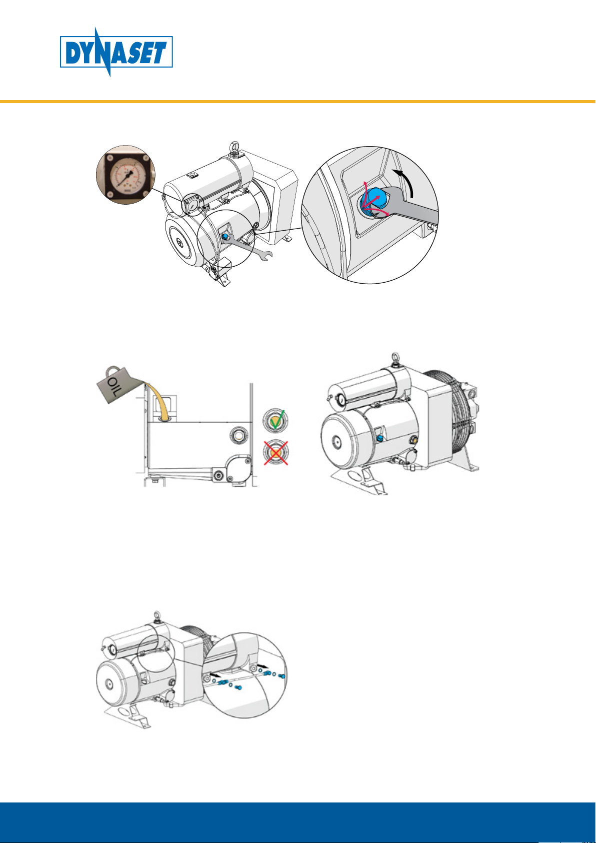
HYDRAULIC ROTARY VANE COMPRESSORS
MAINTENANCE
Depressurize the system completely by loosening the oil filler cap. Little amount of
hot oil may escape from the groove of the oil filler cap when loosing it. Especially if
the compressor has been running recently and there is pressure in the system and
oil is thermally expanded.
Picture 34: Depressurization of the HKL compressor
Dynaset Oy | Menotie 3, 33470 Ylöjärvi | puh. 03 3488 200 | info@dynaset.com | www.dynaset.com
43

HYDRAULIC ROTARY VANE COMPRESSORS
6.1. MAINTENANCE INTERVALS
ATTENTION!
All maintenance must be complied as they are scheduled in this manual.
The following table provides maintenance schedule for the DYNASET HKL
compressor.
MAINTENANCE
CHECK POINTS
Check oil level x
Clean compressor and oil cooler x
Check system for leaks x
Change air intake lter o x
Clean oil return lters * x
Change oil, oil lter and oil return lters x
Change air-oil separating element x
o = Check / change if necessary
x = Change
NOTE!
All installation and service of both hydraulics and electric equipment must
be performing experienced personnel only.
6.2. HYDRAULIC FLUIDS
Daily Monthly or
every 100 h
Every 3
months or
500h
Every 6
months or
1000h
Every 12
months or
2500 h
44
Wide range of standard hydraulic fluids can be used with DYNASET hydraulic
equipment. Depending on the operating temperature, following mineral hydraulic
oils are recommended:
Mineral hydraulic oil Operation temperature up to
ISO VG 32S 60 °C
ISO VG 46S 70 °C
ISO VG 68S 80 °C
NOTE!
Recommended oil viscosity is between 10 to 35 cSt when operating at
normal operating temperature.
Dynaset Oy | Menotie 3, 33470 Ylöjärvi | puh. 03 3488 200 | info@dynaset.com | www.dynaset.com

Synthetic and bio-oils can also be used if their viscosity characteristics and
lubricating efficiency are similar to the mineral oils.
Automatic transmission fluids and even engine oils can be used, provided that
they are allowed to be used in hydraulic system of your base machine.
For the hydraulic fluid change interval follow the base machine’s maintenance
instructions.
To use special hydraulic fluids with DYNASET equipment, please contact the
nearest DYNASET representative for more information.
6.3. COMPRESSOR OILS
Rotoroil F2 compressor oil is recommended as most preferable lubricant. If Rotoroil
lubricants are not available it is allowed to replace them with high quality rotary
vane compressor oil of same viscosity class supplied by other manufacturers.
HYDRAULIC ROTARY VANE COMPRESSORS
MAINTENANCE
Quality Ambient
temperature
Rotoroil 8000 F2 -15 ... +45
Corena S4R -10 ... +45oC 2500h or 12 months Shell Synthetic oil
Rarus SHC 1020 -10 ... +45oC 2500h or 12 months Exxon Mobile Synthetic oil
Oil Change, max hours Supplier Details
o
C 2500h or 12 months Dynaset Synthetic oil
ATTENTION!
Do not mix lubricants of different specification or different brand.
Dynaset Oy | Menotie 3, 33470 Ylöjärvi | puh. 03 3488 200 | info@dynaset.com | www.dynaset.com
45

HYDRAULIC ROTARY VANE COMPRESSORS
6.4. CLEANING THE COMPRESSOR
ATTENTION!
Keep the HKL compressor clean to enable its safe and longlife operation.
Check and clean your HKL compressor after every work shift.
The compressor block and oil cooler should be checked on a daily basis and
cleaned when necessary. To clean the unit use blow gun. Clogged and dirty oil
cooler result compressor’s overheating.
MAINTENANCE
Picture 35: Cleaning oli cooler
ATTENTION!
Use safety glasses when cleaning equipement with blow gun.
6.5. OIL LEVEL CHECK
Location of oil filler cap.
46
Picture 36: Location of oil filler cap
Dynaset Oy | Menotie 3, 33470 Ylöjärvi | puh. 03 3488 200 | info@dynaset.com | www.dynaset.com

HYDRAULIC ROTARY VANE COMPRESSORS
1. Make sure that the compressor is in a horizontal position.
2. Wait for one minute at standstill.
MAINTENANCE
3. Check the oil level from the oil level sight glass. With the compressor at a standstill
and without pressure in the chamber, the oil level must be above the oil level
sight glass. With the compressor running with a load, the oil level must be about
half way up the oil level sight glass.
Picture 37: Oil level of the HKL compressor
Dynaset Oy | Menotie 3, 33470 Ylöjärvi | puh. 03 3488 200 | info@dynaset.com | www.dynaset.com
47

HYDRAULIC ROTARY VANE COMPRESSORS
MAINTENANCE
4. If the compressor requires oil fill up, slowly open the oil filler cap.
NOTE!
Hot oil expands in volume. As a result, oil may escape when the screw
plug is opened at the maximum oil level. In this case, close the oil filler cap
again immediately and carefully clean the oil that has escaped.
5. Add oil up to the maximum level.
6. Close the oil filler cap on filler neck.
48
Dynaset Oy | Menotie 3, 33470 Ylöjärvi | puh. 03 3488 200 | info@dynaset.com | www.dynaset.com

HYDRAULIC ROTARY VANE COMPRESSORS
6.6. OIL UALITY CHECK
Check visually that there is no water mixed into the compressor oil. Oil becomes
turbid when mixed with water. Water causes corrosion increasing risk of damaging
the compressor.
6.7. OIL AND OIL FILTER REPLACEMENT
The HKL compressor must be at operating temperature when changing the oil.
It helps oil draining from the drain hole. Compressor must be stopped during oil
change.
NOTE!
Make sure to use recommended compressor oil.
MAINTENANCE
Add oil of the same oil type from the same manufacturer. Switching over to
another oil type can require flushing of the compressor block and heat exchanger.
NOTE!
DYNASET recommends replacing the oil filter at the same time as oil
change.
Oil fills of HKL compessors
Model Oil ll (litre)
HKL 400 2,5
HKL 801 3
HKL 1300 3
HKL 1800 4,5
HKL 2600 4,5
HKL 4100 12
HKL 5000 12
HKL 7500 25
Dynaset Oy | Menotie 3, 33470 Ylöjärvi | puh. 03 3488 200 | info@dynaset.com | www.dynaset.com
49

HYDRAULIC ROTARY VANE COMPRESSORS
MAINTENANCE
1. Slowly open the oil filler cap and place a suitable container under drain valve.
2. Carefully open the oil drain valve, drain the used oil and close the oil drain valve.
3. Remove the oil filter and dispose the old oil filter cartridge.
50
Dynaset Oy | Menotie 3, 33470 Ylöjärvi | puh. 03 3488 200 | info@dynaset.com | www.dynaset.com

HYDRAULIC ROTARY VANE COMPRESSORS
MAINTENANCE
ATTENTION!
Dispose of the old oil filter in accordance with the applicable regulations.
4. Install new oil filter.
5. Add oil up to the maximum level and screw the oil cap firmly onto the filler neck.
6. Start the compressor and allow it run for three minutes or until thermostatic valve
is opened.
7. Stop the compressor and wait for 1 minute standstill
Dynaset Oy | Menotie 3, 33470 Ylöjärvi | puh. 03 3488 200 | info@dynaset.com | www.dynaset.com
51
HYDRAULIC ROTARY VANE COMPRESSORS
MAINTENANCE
8. Depressurize the system completely by loosening the oil filler cap.
9. Check the oil level and top up the missing oil quantity up to the maximum level
if needed.
6.8. OIL RETURN VALVES REPLACEMENT
Oil return filters should be cleaned at the first oil change.
Futher on, oil return filters should be cleaned after 500 h or every three months.
Replace oil return filters after each 2500h or at least once a year.
52
Dynaset Oy | Menotie 3, 33470 Ylöjärvi | puh. 03 3488 200 | info@dynaset.com | www.dynaset.com

HYDRAULIC ROTARY VANE COMPRESSORS
MAINTENANCE
1. Loosen the pierced screws (1), which secure the fittings of the flexible oil return
tubes (2).
2. Unscrew and remove the oil return valves (3). Wash the valves with detergent
and then dry with compressed air, if there is a lot of crust on the sintered filter,
replace it.
3. Assemble oil return valves in opposite order. Remember always to replace the
O-ring (4).
NOTE!
Be careful with the tightening of the two pierced screws, as they break
easily.
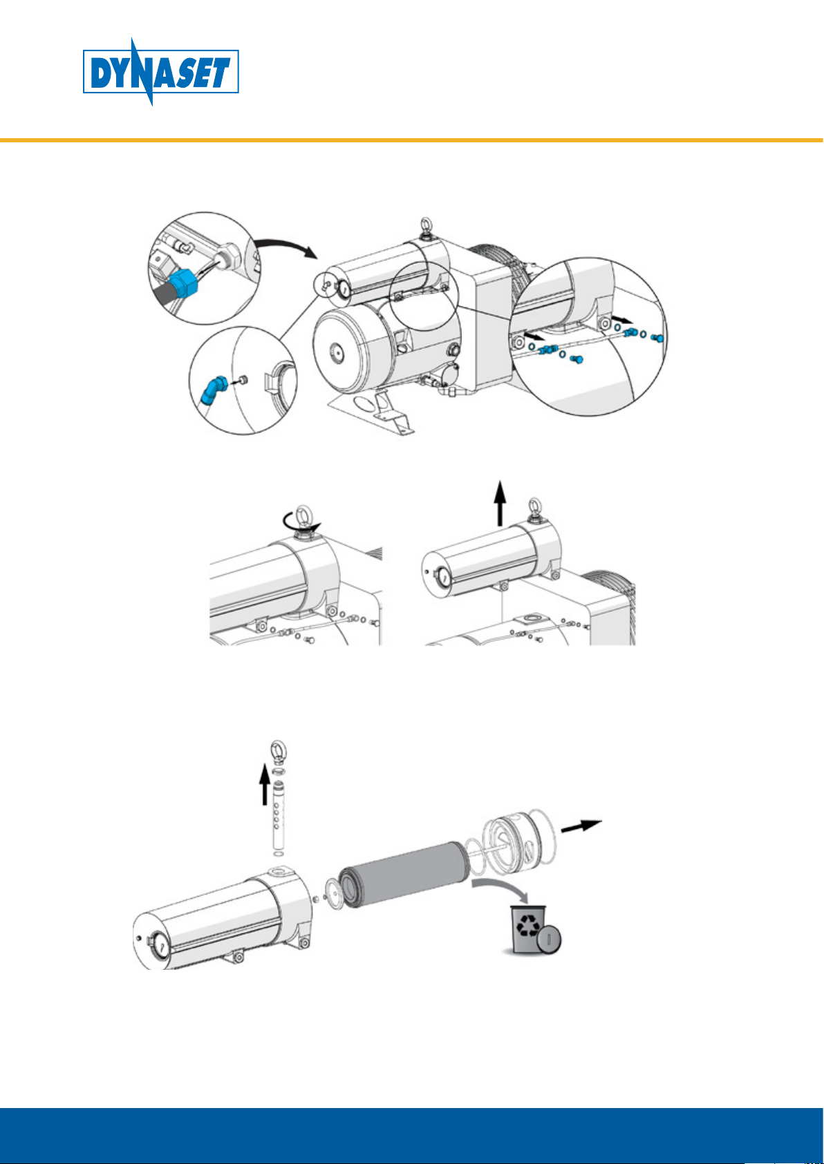
6.9. AIR-OIL SEPARATING ELEMENT REPLACEMENT
ATTENTION!
Dispose of the old separating element in accordance with the applicable
regulations.
Heavily soiled intake air or low-quality oil cause heavier soiling of the separting
element, which can result in the premature need for replacement.
Dynaset Oy | Menotie 3, 33470 Ylöjärvi | puh. 03 3488 200 | info@dynaset.com | www.dynaset.com
53
HYDRAULIC ROTARY VANE COMPRESSORS
MAINTENANCE
1. Remove AP-line connection, return oil line connections and O-PE -switch
connection.
2. Unscrew air-oil-separator screw and lift air-oil-separator.
3. Remove the air-oil-separator screw and pull out air-oil-separating-element.
Dispose the old separating element.
54
Dynaset Oy | Menotie 3, 33470 Ylöjärvi | puh. 03 3488 200 | info@dynaset.com | www.dynaset.com

HYDRAULIC ROTARY VANE COMPRESSORS
MAINTENANCE
4. Install new air-oil-separation element to the air-oil-separator. Grease the o-rings,
check and clean the surfaces.
5. Install air-oil-separator to the compressor.
6. Connect return oil line, O-PE-switch and AP-line.
Dynaset Oy | Menotie 3, 33470 Ylöjärvi | puh. 03 3488 200 | info@dynaset.com | www.dynaset.com
55

HYDRAULIC ROTARY VANE COMPRESSORS
7. Check air-oil-separtor for leaks with the system running.
6.10. REPLACING THE AIR FILTER ELEMENT
MAINTENANCE
ATTENTION!
Dirt and dust particles must not be permitted to get into the air inlet of the
compressor module.
1. Screw off the knob, remove the filter cover and remove the old filter element.
56
ATTENTION!
It is not permissible to clean the filter element; the filter element must
always be replaced in case of soiling!
Dynaset Oy | Menotie 3, 33470 Ylöjärvi | puh. 03 3488 200 | info@dynaset.com | www.dynaset.com

HYDRAULIC ROTARY VANE COMPRESSORS
MAINTENANCE
ATTENTION!
Dispose of the old air filter element according to the applicable
regulations.
2. Carefully remove dust from the filter housing.
3. Insert new filter element and install filter cover.
6.11. ADJUST THE OFF-LOAD PRESSURE
Compressor’s output pressure is adjusted and tested at factory and usually does
not require re-adjustment. However, if re-adjustment is required the procedure is
to be made as described in chapter 6.10.1 and chapter 6.10.2.
Dynaset Oy | Menotie 3, 33470 Ylöjärvi | puh. 03 3488 200 | info@dynaset.com | www.dynaset.com
57
HYDRAULIC ROTARY VANE COMPRESSORS
MAINTENANCE
6.11.1. ADJUSTING THE OFF-LOAD PRESSURE IN STANDARD COMPRESSOR
1. Remove air filter and intake filter cover. Loosen the locknut of the servo valve.
2. Tighten the adjusting screw to increase pressure, loosen the adjusting screw to
decrease pressure. Use separate pressure gauge in pressure line when making
the adjustement.
Nominal output pressure Servo valve’s setting
8 bar 8,5 bar
10 bar 10,5 bar
3. Lock the setting with locknut.
4. Install intake filter cover and air filter.
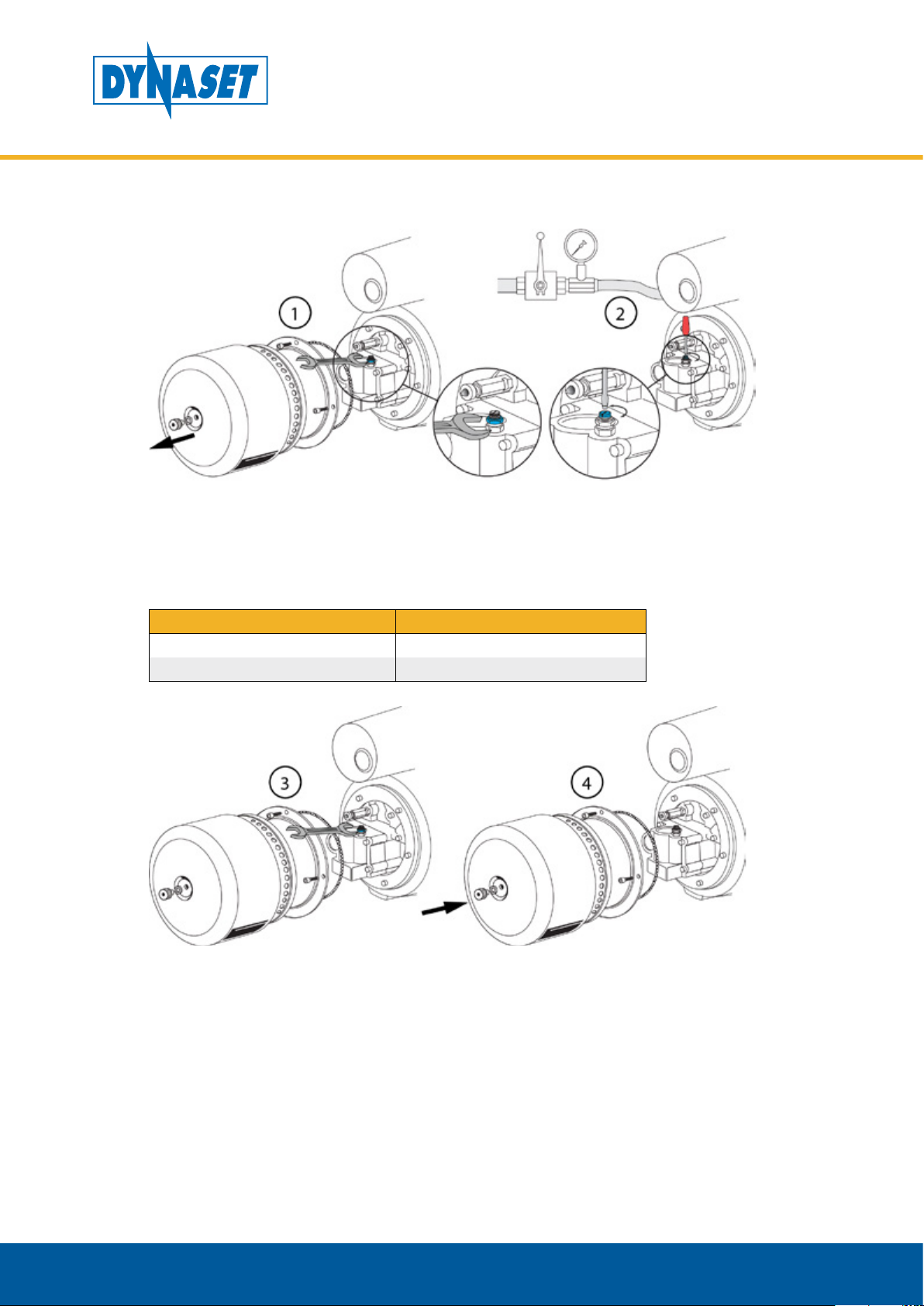
6.11.2. ADJUSTING THE OFF-LOAD PRESSURE IN O-PE COMPRESSOR
O-PE hysteresis locking nut and pilot valve is set in DYNASET factory, dimension H
default factory setting is 17,50...17,70mm.
58
Dynaset Oy | Menotie 3, 33470 Ylöjärvi | puh. 03 3488 200 | info@dynaset.com | www.dynaset.com

NOTE!
HYDRAULIC ROTARY VANE COMPRESSORS
MAINTENANCE
If hysteresis locking nut and pilot valve are on factory settings, phases 1-5
can be skipped
1. Open the hysteresis lock nut (18mm SW) fully open.
2. Tighten the valve from 14mm SW until it stops.
Dynaset Oy | Menotie 3, 33470 Ylöjärvi | puh. 03 3488 200 | info@dynaset.com | www.dynaset.com
59

HYDRAULIC ROTARY VANE COMPRESSORS
MAINTENANCE
3. Start gently to loosen valve from 14mm SW, rotate counter clockwive until valve
feels loose.
4. Tighten 14mm SW 1/4 turn back.
5. Lock the hysteresis lock nut.
60
Dynaset Oy | Menotie 3, 33470 Ylöjärvi | puh. 03 3488 200 | info@dynaset.com | www.dynaset.com

HYDRAULIC ROTARY VANE COMPRESSORS
MAINTENANCE
6. Start the compressor.
7. Start closing the air supply lines valve slowly until the air pressure is desired. (For
example 8 bar, it depends on what pressure servo valve is set on, servo valve
pressure should be more than O-PE valve.)
8. Keep compressor runnig and check that air pressure is constant.
9. Loose the 12mm SW locking nut on pilot valve.
Dynaset Oy | Menotie 3, 33470 Ylöjärvi | puh. 03 3488 200 | info@dynaset.com | www.dynaset.com
61

HYDRAULIC ROTARY VANE COMPRESSORS
MAINTENANCE
10. Start to open pilot valve adjusting knob on the top of the pilot valve until
compressor goes on free flow state and pressure starts to drop to ~2 bar.
11. Tighten the locking nut on pilot valve.
62
Dynaset Oy | Menotie 3, 33470 Ylöjärvi | puh. 03 3488 200 | info@dynaset.com | www.dynaset.com

6.12. TROUBLESHOOTING
Performing the maintenance tasks requires a qualified hydraulic mechanic.
Please, contact DYNASET authorized workshop or dealer for more maintenance
information.
FAILURE REASON CORRECTIVE ACTION
HYDRAULIC ROTARY VANE COMPRESSORS
MAINTENANCE
Malfunction on
compressor’s hyrdaulic
control valve.
Check and repair.
Compressor’s excessive
internal pressure.
Compressor does not start
while carrier’s engine is
running and hydraulic
system is on.
FAILURE REASON CORRECTIVE ACTION
Compressor starts hardly.
Failure in hydraulic system.
Air pressure in delivery line
disrupts compressor’s start.
Failure in hydraulic system.
Air pressure in delivery line
disrupts compressor’s start.
Check the minimum pressuse
or non return valve and repair
possible blowing.
Check that the hyraulic ow and
pressure are sucient. Adjust
when necessary.
Check the hydraulic motor
for possible leakage. Replace
damaged parts if necessary.
Depressurize the system line prior
to starting the compressor. It is
recommended to install solenoid
control valve for o-load valve,
especially if the pneumatic system
is provided with an air reservoir.
Check that the hyraulic ow
and pressure are sucient.
Adjust when necessary.
Check the hydraulic motor
for possible leakage. Replace
damaged parts if necessary.
Depressurize the system
line prior to starting
the compressor. It is
recommended to install
solenoid control valve for
o-load valve, especially if the
pneumatic system is provided
with an air reservoir.
Dynaset Oy | Menotie 3, 33470 Ylöjärvi | puh. 03 3488 200 | info@dynaset.com | www.dynaset.com
63

HYDRAULIC ROTARY VANE COMPRESSORS
MAINTENANCE
FAILURE REASON CORRECTIVE ACTION
Servo valve’s incorrect setting.
Safety valve opens due to
either failure or incorrect
setting of servo valve.
Air pressure does not
achieve requested rate.
FAILURE REASON CORRECTIVE ACTION
Compressor does not
produce compressed air.
Failure in hydraulic system.
Air intake lter is clogged. Check and replace.
Oil separator’s iter element(s)
are clogged.
Delivery line is closed or
possible malfunction in
pneumatic executor.
Sevo valve’s failure or
incorrect setting (i.e. adjusted
pressure is lower than setting
of minimum pressure / non
return valve).
Air intake valve does not
open.
Check and adjust servo valve
when necessary.
Check and adjust servo valve.
Check that the hydraulic ow
and pressure are sucient.
Adjust when necessary.
Check the hydraulic motor
for possible leakage. Replace
damaged parts if necessary.
Check and replace lters if
necessary.
Check and repair.
Check and repair.
Check the valve and repair.
Also check the whole valve
block to order to nd out
possible malfunction.
FAILURE REASON CORRECTIVE ACTION
Filters of the oil return valves
Excessive oil consumption.
FAILURE REASON CORRECTIVE ACTION
Compressor is overheating
are clogged.
Oil separator’s lter element(s)
is clogged.
Dirty oil cooler. Clean the oil cooler.
High ambient temperature.
Low oil level.
Compressor oil does not
circulate through oil cooler
due to seizure of thermostacic
by-pass valve.
Insucient cooling capacity.
Check and clean. Replace if
necessary.
Check and replace lter
elements if necessary.
Arrange sucient ventilation
to the operating environment.
Add compressor oil to the
required level.
Check and repair the valve.
Arrange sucient ventilation
to the operating environment.
64
Dynaset Oy | Menotie 3, 33470 Ylöjärvi | puh. 03 3488 200 | info@dynaset.com | www.dynaset.com

HYDRAULIC ROTARY VANE COMPRESSORS
7. MANUFACTURER’S LIMITED WARRANTY
1. Warranty coverage
All hydraulic accessories manufactured by DYNASET OY are subject to the terms
and conditions of this limited warranty. Products are warranted to the original
purchaser to be free from defects in materials or workmanship. Exclusions from
warranty are explained in item Exclusions from warranty.
2. Beginning of warranty period
Warranty period begins from the delivery date of the product. Delivery is
considered to be done on the date when installation has been accomplished or
purchaser has taken the product in use. Product is considered as taken in use at the
date when DYNASET OY has delivered the product to purchaser, unless separately
agreed otherwise by written agreement.
3. Warranty period
Warranty period is twenty four (24) months based on maximum of 2000 hours
usage during this time period. In cases where the system is provided complete with
certain special components (e.g. drive unit), those components are considered as
a subject to their manufacturer’s warranty.
WARRANTY
4. Warranty procedures
Immediately upon identifying a problem which purchaser believes to be a failure
subject to the product’s limited warranty, purchaser must contact primary to the
seller of the product. Contact must be made as soon as possible, latest thirty (30)
days after the problem was identified. Seller and/or manufacturer technical staff
determines the nature of the problem primarily by phone or e-mail. Purchaser
commits to give necessary information and to perform routine diagnostic
procedures in order to determine the nature of the problem and necessary
procedures.
5. Warranty repairs
If the product is found to be defective during the warranty period, DYNASET
OY will, at its option, either repair the product, author it to be repaired at its
authorized workshop or exchange the defective product. If the product must be
repaired elsewhere than premises of DYNASET OY or authorized workshop, all
costs excluded from this warranty (traveling and waiting hours, daily allowance,
traveling expenses and uninstallation/reinstallation costs) will be charged from
the purchaser. If the problem is not covered by this limited warranty, DYNASET OY
has the right to charge purchaser of troubleshooting and repairing.
6. Delivery terms of warranty repair
If the product is found possible to be defective under this limited warranty and it
needs to be repaired, DYNASET OY gives Warranty Return Number (WRN). Items
being returned must be shipped, at the purchaser’s cost, adequately packed for
shipment, to the DYNASET OY or to other location authored by DYNASET OY.
Shipment documents must contain:
• Purchaser’s name and contact information
• Receipt of original purchase
• WRN code
• Problem description
Dynaset Oy | Menotie 3, 33470 Ylöjärvi | puh. 03 3488 200 | info@dynaset.com | www.dynaset.com
65

HYDRAULIC ROTARY VANE COMPRESSORS
WARRANTY
7. Warranty of repaired product
Warranty period of the product repaired under this limited warranty continues to
the end of original warranty period.
8. Exclusions from warranty
This warranty shall not apply to:
• Failures due to normal wear and tear, improper installation, misuse, abuse,
negligence, purchaser selection of improper product to intended use, accident,
improper filtration of hydraulic oil or intake water or lack of maintenance.
• Cost of maintenance, adjustments, installation or startup.
• Coating, hydraulic oil, quick couplings and interconnection hoses (internal or
external to system assemblies).
• Products altered or modified in a manner not authorized by DYNASET OY in
writing.
• Products which have been repaired during warranty period by others than
DYNASET OY or its authorized workshop.
• Costs of any other damage or loss, whether direct, indirect, incidental, special
or consequential, arising out of the use of, or the inability to use, the product.
• Telephone or other communications expense.
• Product that is used in exceptional conditions, considered to cause excessive
wear and tear.
• Faults caused by nature phenomenon’s like flood, thunder, etc.
© DYNASET OY, all rights reserved
66
Dynaset Oy | Menotie 3, 33470 Ylöjärvi | puh. 03 3488 200 | info@dynaset.com | www.dynaset.com

8. PRODUCT DISPOSAL
Dispose and recycle all DYNASET products and their packaging environmentally
responsible way.
Do not dispose used oils, electrical components, batteries or any other hazardous
waste with normal waste. They are harmful for the environment and can be
recycled for re-use.
Contact your local waste recycling facility for more information about recycling
hazardous waste.
NOTE!
Always act according to the waste legislation, regulations and
recommendations in waste disposal and waste recycling issued by your
local authorities.
HYDRAULIC ROTARY VANE COMPRESSORS
PRODUCT DISPOSAL
Dynaset Oy | Menotie 3, 33470 Ylöjärvi | puh. 03 3488 200 | info@dynaset.com | www.dynaset.com
67

HYDRAULIC ROTARY VANE COMPRESSORS
PRODUCT DISPOSAL
68
Dynaset Oy | Menotie 3, 33470 Ylöjärvi | puh. 03 3488 200 | info@dynaset.com | www.dynaset.com

HYDRAULIC ROTARY VANE COMPRESSORS
DECLARATION OF CONFORMITY
9. DECLARATION OF CONFORMITY
We hereby declare that the design and manufacture of the product stated below
are in conformity with the provisions of the European Parliament and Councils on
the harmonization of the laws of Member States on the safety of machines.
Machine directive 2006/42/EC
LVD directive 2014/35/EU
EMC directive 2014/30/EU
RoHS directive 2011/65/EU
PED directive 2014/68/EU
Applied conformity standards:
CEN EN ISO 4413: EN ISO 4413:2010 Hydraulic fluid power -
General rules and safety requirements for systems and their
components.
EN60204-1 Safety of machinery – Electrical equipment of
machines.
Manufacturer: DYNASET Oy
Menotie 3, FI-33470 Ylöjärvi, Finland
Product group: HYDRAULIC COMPRESSORS
Product: HKL Hydraulic rotary vane compressors
If the device has been modified by someone other than the manufacturer or
without the manufacturer’s permission, this declaration is not valid.
Timo Nieminen
R&D Manager
Ylöjärvi, Suomi, 20.04.2016
Dynaset Oy | Menotie 3, 33470 Ylöjärvi | puh. 03 3488 200 | info@dynaset.com | www.dynaset.com
69

HYDRAULIC ROTARY VANE COMPRESSORS
DECLARATION OF CONFORMITY
70
Dynaset Oy | Menotie 3, 33470 Ylöjärvi | puh. 03 3488 200 | info@dynaset.com | www.dynaset.com
HYDRAULIC ROTARY VANE COMPRESSORS
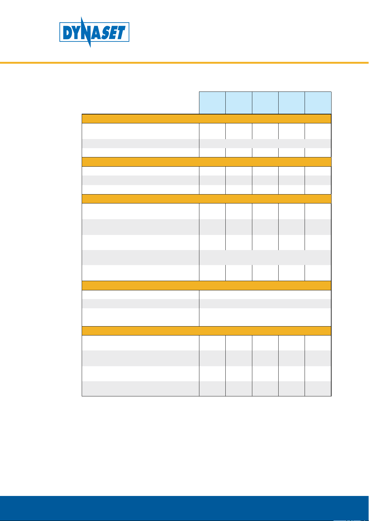
10. TECHNICAL SPECIFICATIONS
TECHNICAL SPECIFICATIONS
HKL 400
/8-24
HKL 801
/8-26
HKL
1300
/8-38
HKL
1300
/8-46 *
HKL
1800
/8-46
DISCHARGE CHARACTERISTICS
Flow rate max. at ref.
conditions **
l/min
(cfm)
400
(14)
800
(28)
1300
(46)
1300
(46)
1800
(64)
Pressure max. bar (psi) 8 (116)
Compressed air connection AP BSP 3/8” BSP 1/2” BSP 1/2” BSP 1/2” BSP 3/4”
HYDRAULIC CONNECTIONS
Pressure line P BSP 1/2” BSP 1/2” BSP 1/2” BSP 1/2” BSP 1/2”
Return line T BSP 1/2” BSP 1/2” BSP 1/2” BSP 1/2” BSP 1/2”
Drain line D - - - - -
HYDRAULIC POWER REQUIREMENTS
Oil ow min. l/min
(gmp)
Oil ow max. l/min
(gmp)
10
(2.64)
35
(9.25)
Pressure at nominal ow bar (psi) 120
(1740)
14
(3.70)
37
(9.77)
210
(3046)
20
(5.28)
60
(15.85)
210
(3046)
23
(6.08)
66
(17.44)
170
(2466)
23
(6.08)
66
(17.44)
210
(3046)
Pressure max. bar (psi) 250
(3626)
Pressure when unloaded bar
(psi)
80
(1160)
140
(2031)
150
(2176)
130
(1885)
150
(2176)
HYDRAULIC FLUID REQUIREMENTS
Viscocity cSt 10-200 / optimum 25-35
Temperature *** ° C (° F) max. 70
(158)
Filter ratio μm 25 or better
OVERALL DIMENSIONS
Length mm (in) 525
(20.7)
Width mm (in) 250
(9.8)
Height mm (in) 325
(12.8)
Weight kg (lbs) 30
(66.1)
Gallons are U.S. liquid gallons
640
(25.2)
320
(12.6)
520
(20.5)
55
(121.3)55(121.3)
640
(25.2)
320
(12.6)
520
(20.5)
640
(25.2)
320
(12.6)
520
(20.5)
55
(121.3)
* Low pressure model (170 bar).
** According to ISO 1217 (19.6) at discharge pressure of 6 bar.
*** READ CHAPTER “6.2. Hydraulic uids”
Dynaset Oy | Menotie 3, 33470 Ylöjärvi | puh. 03 3488 200 | info@dynaset.com | www.dynaset.com
810
(31.9)
390
(15.4)
620
(24.4)
103
(227.1)
71

HYDRAULIC ROTARY VANE COMPRESSORS
TECHNICAL SPECIFICATIONS
HKL
2600
/8-65
HKL
2600
/8-82 *
HKL
4100
/8-113
HKL
5000
/8-135
HKL
7500
/8-150
DISCHARGE CHARACTERISTICS
Flow rate max. at ref. conditions **l/min
(cfm)
2600
(92)
2600
(92)
4100
(145)
5000
(177)
7500
(265)
Pressure max. bar (psi) 8 (116)
Compressed air connection AP BSP 3/4” BSP 3/4” BSP 1” BSP 1” BSP 1 1/4”
HYDRAULIC CONNECTIONS
Pressure line P BSP 3/4” BSP 3/4” BSP 3/4” BSP 3/4” BSP 1”
Return line T BSP 1” BSP 1” BSP 1” BSP 1” BSP 1”
Drain line D - - - - T15
HYDRAULIC POWER REQUIREMENTS
Oil ow min. l/min
(gmp)
Oil ow max. l/min
(gmp)
33
(8.72)
65
(17.17)
Pressure at nominal ow bar (psi) 210
(3046)
41
(10.83)
82
(21.66)
170
(2466)
Pressure max. bar (psi) 250
Pressure when unloaded bar
(psi)
150
(2176)
135
(1958)
(3626)
74
(19.55)
113
(29.85)
210
(3046)
150
(2176)
74
(19.55)
135
(35.66)
210
(3046)
150
(2176)
90
(23.77)
150
(39.63)
260
(3771)
280
(4061)
160
(2901)
HYDRAULIC FLUID REQUIREMENTS
Viscocity cSt 10-200 / optimum 25-35
Temperature *** ° C (° F) max. 70
(158)
Filter ratio μm 25 or better
OVERALL DIMENSIONS
Length mm (in) 810
(31.9)
Width mm (in) 390
(15.4)
Height mm (in) 620
(24.4)
Weight kg (lbs) 103
(227.1)
Gallons are U.S. liquid gallons
810
(31.9)
390
(15.4)
620
(24.4)
103
(227.1)
890
(35.0)
515
(20.3)
790
(31.1)
185
(407.9)
* Low pressure model (170 bar).
** According to ISO 1217 (19.6) at discharge pressure of 6 bar.
*** READ CHAPTER ”6.2. Hydraulic uids”
890
(35.0)
515
(20.3)
790
(31.1)
185
(407.9)
1100
(43.3)
890
(35.0)
900
(34.4)
330
(727.6)
72
Dynaset Oy | Menotie 3, 33470 Ylöjärvi | puh. 03 3488 200 | info@dynaset.com | www.dynaset.com

© DYNASET OY, all rights reserved

Menotie 3
FI-33470 Ylöjärvi, Finland
tel: +358 3 3488 200
info@DYNASET.com
ELECTRICITY
HG Hydraulic Generator
HGV POWER BOX Variable Hydraulic Generator System
HGV Variable Hydraulic Generator System
HWG Hydraulic Welding Generator
HGG Hydraulic Ground Power Generator
HIGH PRESSURE WATER
HPW Hydraulic High Pressure Water Pump
HPW Hydraulic Power Washer
KPL High Pressure Street Washing Unit
HPW-DUST High Pressure Dust Suppression System
PPL High Pressure Pipe Cleaning Unit
HPW-FIRE High Pressure Fireghting System
FP Fire Fighting Piercing Kit
HDF Hydraulic Drilling Fluid Pump
JPL High Pressure Bin Washing System
HSP Hydraulic Submersible Pump
MAGNET POWER
HMG PRO Hydraulic Magnet Generator
MAG Lift Magnet
HMAG PRO Hydraulic Magnet
VIBRATION
HVB Hydraulic Vibra
HVD Hydraulic Directional Vibra
HVC Hydraulic Vibration Compactor
HRC Hydraulic Reversal Cylinder
POWER BOOSTING
HPI Hydraulic Pressure Intensier
HPI-C Hydraulic Pressure Intensier for Cylinder
COMPRESSED AIR
HK Hydraulic Piston Compressor
HKL Hydraulic Rotary Vane Compressor
HKR Hydraulic Screw Compressor
www.DYNASET.com
KNOW-HOW
Hydraulic Power Take-o (PTO)
Hydraulic Power Unit Technology
HEU Hydraulic Expansion Unit
HRU Hydraulic Rescue Unis
De-Icing Technology
Installation Valves
HHK Hydraulic Grinder
HV/HVY Hydraulic Winch / Winch Unit
 Loading...