

Dynaset HGV Power Box 3.5, HGV Power Box 6.5, HGV Power Box 10, HGV Power Box 15, HGV Power Box 20 User Manual
...
06/18
rev 1.2
USER MANUAL
HGV POWER BOX / HGV BASIC
VARIABLE HYDRAULIC GENERATOR SYSTEMS
HGV Power Box 3,5
HGV Power Box 6,5
HGV Power Box 10
Download PDF version from www.Dynaset.com/manuals Keycode: B36FKP
HGV Power Box 15
HGV Power Box 20
HGV Basic 3,5
HGV Basic 6,5
HGV Basic 10
HGV Basic 12
HGV Basic 15
HGV Basic 20


Congratulations!
You have just purchased DYNASET hydraulic equipment!
The equipment allows you to maximize the productivity and
efficiency of your mobile machine. Read this User Manual
before using your new equipment. It contains important
information that will help you to take the full advance of the
technical features avaible in your equipment.
Please contact us for any feedback you might have on our
products. Your feedback is important to us for improving our
products and customer service.
We are constantly developing and releasing new innovations.
Please visit on our website and social media channels for the
latest news and updates.
www.dynaset.com
info@dynaset.com
www.facebook.com/dynaset
www.youtube.com/dynasetoy
www.twitter.com/Dynaset_ofcl
www.instagram.com/dynaset_official
Subscribe to our newsletter. Follow the QR
code!
Dynaset Oy | Menotie 3, FI-33470 Ylöjärvi, Finland | tel: +358 3 3488 200 | info@dynaset.com | www.dynaset.com
3

VARIABLE HYDRAULIC GENERATOR SYSTEM
TABLE OF CONTENTS
1. GENERAL 9
1.1. PRODUCT INFORMATION 9
1.2. PRODUCT IDENTIFICATION 9
1.2.1. HGV POWERBOX 9
1.2.2. HGV BASIC
10
1.3. TYPE PLATES 11
1.4. DYNASET HGV POWER BOX SYSTEMS LINE-UP 12
1.5. DYNASET HGV BASIC SYSTEMS LINE-UP 12
1.6. MAIN ASSEMBLY COMPONENTS OF HGV POWER BOX SYSTEM 13
1.7. MAIN ASSEMBLY COMPONENTS OF HGV BASIC SYSTEMS 14
1.7.1. MAIN ASSEMBLY COMPONENTS OF HGV PUMP 14
1.7.2. MAIN ASSEMBLY COMPONENTS OF HGV GENERATOR
1.7.3. MAIN ASSEMBLY COMPONENTS OF HGV COOLER
1.7.4. MAIN ASSEMBLY COMPONENTS OF HGV TANK
16
15
16
1.8. MAIN ASSEBLY OF THE ELECTRIC CENTRAL 17
1.9. IP(Ingress Protection) CLASSIFICATION 17
1.10. VOLTAGE AND FREQUENCY 18
1.11. HYDRAULIC EQUIPMENT 20
1.12. ELECTRIC EQUIPMENT 20
1.12.1. SINGLE-PHASE SOCKET PLUG TYPE 21
2. SAFETY 25
2.1. SAFETY PRECAUTIONS 25
2.2. SAFETY EQUIPMENT 26
2.3. OPERATING SAFETY 26
2.4. MAINTENANCE SAFETY 27
2.5. WARNING LABELS 28
3. OPERATING PRINCIPLES 29
3.1. OPERATING DESCRIPTION 29
3.2. AUTOMATIC HYDRAULIC FLOW CONTROL 30
4. INSTALLATION 31
4.1. BEFORE INSTALLATION 31
4.1.1. BASE MACHINE 31
4.1.2. HYDRAULIC FLUIDS
4.1.3. IP CODE REQUIREMENTS
32
32
Dynaset Oy | Menotie 3, 33470 Ylöjärvi | puh. 03 3488 200 | info@dynaset.com | www.dynaset.com

VARIABLE HYDRAULIC GENERATOR SYSTEM
TABLE OF CONTENTS
4.2. INSTALLING DYNASET HGV POWERBOX SYSTEM 32
4.2.1. HYDRAULIC PUMP & HPTO 32
4.2.2. POWER BOX PLACEMENT AND INSTALLATION MEASUREMENTS
33
4.3. INSTALLING HGV BASIC SYSTEM 35
4.3.1. HYDRAULIC PUMP & DYNASET HPTO 35
4.3.2. HYDRAULIC GENERATOR
4.3.3. COOLER
4.3.4. OIL TANK
4.3.5. ELECTRIC CENTRAL
35
36
35
36
4.4. HYDRAULIC AND ELECTRIC CONNECTIONS 37
4.5. ADJUSTING THE PUMP RPM 42
4.6. OUTPUT FREQUENCY CHECK AT START-UP 42
4.7. OUTPUT FREQUENCY ADJUSTING 43
5. OPERATION 47
5.1. STARTING AND STOPPING THE HGV SYSTEM. 47
5.2. AMBIENT TEMPERATURE 48
6. MAINTENANCE 49
6.1. MAINTENANCE INTERVALS 49
6.2. HYDRAULIC FLUIDS 50
6.3. CLEANING HGV GENERATOR 50
6.4. TEST SAFETY DEVICES 50
6.5. OIL LEVEL CHECK 51
6.6. OIL CHANGE 52
6.7. OIL FILTER CHANGE 53
6.8. TROUBLESHOOTING 54
7. MANUFACTURER’S LIMITED WARRANTY 57
8. PRODUCT DISPOSAL 59
9. DECLARATION OF CONFORMITY 61
10. TECHNICAL SPECIFICATIONS 63
Dynaset Oy | Menotie 3, 33470 Ylöjärvi | puh. 03 3488 200 | info@dynaset.com | www.dynaset.com

VARIABLE HYDRAULIC GENERATOR SYSTEM
TABLE OF PICTURES
Picture 1: HGV PowerBox identification key .................................................................................................................... 9
Picture 2: HGV Basic identification key .......................................................................................................................... 10
Picture 3: HGV PowerBox type plate .............................................................................................................................. 11
Picture 4: HGV Power box system line-up ......................................................................................................................12
Picture 5: HGV Basic system line-up .............................................................................................................................. 12
Picture 6: HGV PowerBox system’s main components ................................................................................................... 13
Picture 7: HGV Basic system’s components .................................................................................................................... 14
Picture 8: HGV pump’s main components ......................................................................................................................14
Picture 9: HGV generator’s main components ............................................................................................................... 15
Picture 10: Oil cooler main components ........................................................................................................................ 16
Picture 11: Oil tank main components ..........................................................................................................................16
Picture 12: HGV systems electric central’s components ................................................................................................. 17
Picture 13: Single phase voltage and frequency map .................................................................................................... 19
Picture 14: Three phase voltage and frequency world map ........................................................................................... 19
Picture 15: Single phase sockets and plugs ...................................................................................................................21
Picture 16: Single phase plug and socket map ..............................................................................................................22
Picture 17: IEC60309 three phase sockets and plugs .....................................................................................................22
Picture 18: NEMA three phase sockets and plugs...........................................................................................................23
Picture 19: Operating principle ......................................................................................................................................29
Picture 20: Positioning of the HGV system according the IP23 classification ..................................................................32
Picture 21: Hydraulic pump installed to transmissions PTO ........................................................................................... 32
Picture 22: Hydraulic pump installed to engines PTO ....................................................................................................33
Picture 23: Palcement of the HGV PowerBox system .....................................................................................................33
Picture 24: HGV Power Box installation measurements ................................................................................................. 34
Picture 25: 6,5 KVA HG hydraulic generator .................................................................................................................. 35
Picture 26: DYNASET Oil cooler .....................................................................................................................................35
Picture 27: Oil Tank ........................................................................................................................................................ 36
Picture 28: Electric central ............................................................................................................................................. 36
Picture 29: HGV Power Box S hydraulic connections ...................................................................................................... 37
Picture 30: HGV Power Box S hydraulic connections ...................................................................................................... 37
Picture 31: HGV Power box hydraulic schema ................................................................................................................ 38
Picture 32: HGV Power Box electric connections ............................................................................................................ 38
Picture 33: HGV Power box electric schema ...................................................................................................................39
Picture 34: HGV basic systems hydraulic connections .................................................................................................... 40
Picture 35: HGV basic systems hydraulic schema ...........................................................................................................41
Picture 36: HGV basic systems electric connections ....................................................................................................... 41
Picture 37: HGV systems frequency check 1 ...................................................................................................................43
Picture 38: HGV systems frequency check 2 ...................................................................................................................43
Picture 39: Adjusting HGV systems frequency 1 ............................................................................................................44
Picture 40: Adjusting HGV systems frequency 2 ............................................................................................................45
Picture 41: Adjusting HGV systems frequency 3 ............................................................................................................45
Picture 42: Starting HGV system 1 .................................................................................................................................47
Picture 43: Starting HGV system 2 .................................................................................................................................47
Picture 44: Starting HGV system 3 .................................................................................................................................47
Picture 45: Power take off in higher temperatures ........................................................................................................48
Picture 46: Testing safety equipment ............................................................................................................................ 51
Dynaset Oy | Menotie 3, 33470 Ylöjärvi | puh. 03 3488 200 | info@dynaset.com | www.dynaset.com

VARIABLE HYDRAULIC GENERATOR SYSTEM
TABLE OF PICTURES
Picture 47: Oil tanks oil level gauge ...............................................................................................................................51
Picture 48: Oil change ...................................................................................................................................................52
Picture 49: Oil filter change ........................................................................................................................................... 53
Dynaset Oy | Menotie 3, 33470 Ylöjärvi | puh. 03 3488 200 | info@dynaset.com | www.dynaset.com

VARIABLE HYDRAULIC GENERATOR SYSTEM
TABLE OF PICTURES
Dynaset Oy | Menotie 3, 33470 Ylöjärvi | puh. 03 3488 200 | info@dynaset.com | www.dynaset.com

VARIABLE HYDRAULIC GENERATOR SYSTEMS
1. GENERAL
This manual contains general information about assembly, installation, operation
and maintenance of the DYNASET HGV variable hydraulic generator systems.
ATTENTION!
Read this operating manual before the use of HGV variable hydraulic
generator system, to ensure proper handling, operation and maintenance
right from the beginning. Pay particular attention to all warning and safety
instructions.
1.1. PRODUCT INFORMATION
GENERAL
HGV variable hydraulic generator system is a compact and integrated all-in-one
generator system designed for mobile installation. HGV systems use base machine’s
power source to operate and produce high quality electricity for powering various
electric equipment.
HGV systems come in two forms, PowerBox and Basic. In HGV PowerBox main
components are fitted in to a compact casing. HGV Basic is a component kit that
includes same main components than the PowerBox system but whit out the
compact casing.
1.2. PRODUCT IDENTIFICATION
1.2.1. HGV POWERBOX
HGV PowerBox system has an identification key. The identification key of the
system informs the main specifications of the system. Identification key can be
found from the products type plate which are attached as shown in picture 6.
The HGV PowerBox’s product identification key includes following information.
Picture 1: HGV PowerBox identification key
1. Product Group HGV PowerBox Variable Hydraulic Generators.
2. Presents the box’ size class.
3. Nominal power output in kVA
4. Main voltage of the generator.
Dynaset Oy | Menotie 3, 33470 Ylöjärvi | puh. 03 3488 200 | info@dynaset.com | www.dynaset.com
9

5. Nominal Hydraulic Flow. The theoretical minimal hydraulic ow needed to operate
the HGV system.
6. Presents the voltage system on the base machine either 12V or 24V.
7. Oil cooler size in kW.
8. Oil tank size 18/36 in liters (4.75/9.5 gal).
1.2.2. HGV BASIC
HGV basic system has an identification key. The identification key of the system
informs the main specifications of the system.
The HGV Basic’s product identification key includes following information.
VARIABLE HYDRAULIC GENERATOR SYSTEMS
GENERAL
Picture 2: HGV Basic identification key
1. Product Group HGV Variable Hydraulic Generator System.
2. NominAl Power output. Presents the HG hydraulic generator’s nominal power
output in kVA.
3. Generator’s main voltage, 230 or 400 VAC.
4. Hydraulic nominal flow. Presents the theoretical minimal hydraulic flow needed
to operate the HGV system.
5. electric equipment. Presents the electric equipment on HG hydraulic generator.
READ CHAPTER ”1.12. Electric equipment” for more information..
6. The voltage system on the base machine truck (T) or van (V), either 12V or 24V.
7. Operating method. Presents the if the hydraulic pump is operatable (D) or not
operatable (C) when driving the base machine.
8. Pump size. Presents the the hydraulic pump’s size.
9. Pump rotation direction. Presents the rotation direction of the hydraulic pump.
10. Connection flange. Presents the hydraulic pump’s connection flange type to
the base machine’s engine.
10
Dynaset Oy | Menotie 3, 33470 Ylöjärvi | puh. 03 3488 200 | info@dynaset.com | www.dynaset.com

1.3. TYPE PLATES
HVG PowerBox systems have type plate to identify it. Also every component of the
system has its own type plate. HGV PowerBox’s type plate is presented in picture
3. The placement of the type plate is presented in picture 6.
HGV basic systems on the other hand have type plates only on the systems main
components.
On the HGV Power box’s type plate are the following information
VARIABLE HYDRAULIC GENERATOR SYSTEMS
GENERAL
Picture 3: HGV PowerBox type plate
1. Product identification key
2. Product code
3. Serial number
4. Minimal hydraulic flow
5. Maximum hydraulic pressure
6. Production month / year
7. Output power and main voltage
8. Manufacturer’s contact
information
Dynaset Oy | Menotie 3, 33470 Ylöjärvi | puh. 03 3488 200 | info@dynaset.com | www.dynaset.com
11

VARIABLE HYDRAULIC GENERATOR SYSTEMS
1.4. DYNASET HGV POWER BOX SYSTEMS LINEUP
DYNASET HGV Power box systems come in two standard box sizes S and M. Both
sizes come with hydraulic pump, generator, cooler and tank combination. Below
are listed the available standard systems.
GENERAL
Picture 4: HGV Power box system line-up
• HGV Power box 3,5 kVA S
• HGV Power box 6,5 kVA S
• HGV Power box 10 kVA S
• HGV Power box 15 kVA M
• HGV Power box 20 kVA M
1.5. DYNASET HGV BASIC SYSTEMS LINEUP
DYNASET HGV Basic systems consists of hydraulic pump, generator, cooler and
tank combination. Below are listed the standard systems.
1. HGV 3,5 kVA 230 V - R 45 LS
2. HGV 6,5 kVA 400 V - R 45 LS
3. HGV 10 kVA 400 V - R 45 LS
4. HGV 10 kVA 400 V - H90 LS
5. HGV 12 kVA 400 V - H90 LS
6. HGV 15 kVA 400 V - H90 LS
7. HGV 20 kVA 400 V - R140 LS
12
Picture 5: HGV Basic system line-up
Dynaset Oy | Menotie 3, 33470 Ylöjärvi | puh. 03 3488 200 | info@dynaset.com | www.dynaset.com

VARIABLE HYDRAULIC GENERATOR SYSTEMS
GENERAL
1.6. MAIN ASSEMBLY COMPONENTS OF HGV POWER BOX SYSTEM
Picture 6: HGV PowerBox system’s main components
1. Type plate
2. Variable hydraulic pump
3. Hydraulic generator
4. Cooler
5. Oil Tank
6. Hydraulic pressure line (P)
7. Hydraulic suction line (S)
8. Drain line (Dr)
9. LS - line (LS)
10. AC power outlet to central box
11. Control voltage 12/24 V
12. Cooler supply voltage 12/24V
Dynaset Oy | Menotie 3, 33470 Ylöjärvi | puh. 03 3488 200 | info@dynaset.com | www.dynaset.com
13

VARIABLE HYDRAULIC GENERATOR SYSTEMS
1.7. MAIN ASSEMBLY COMPONENTS OF HGV BASIC SYSTEMS
1 2 3 4
Picture 7: HGV Basic system’s components
GENERAL
1. DYNASET Hydraulic pump
2. DYNASET HG Hydraulic
generator
3. DYNASET Oil cooler
4. DYNASET Oil tank
1.7.1. MAIN ASSEMBLY COMPONENTS OF HGV PUMP
14
Picture 8: HGV pump’s main components
A. 28, 45, 60, 71 and 100
high speed models
Dynaset Oy | Menotie 3, 33470 Ylöjärvi | puh. 03 3488 200 | info@dynaset.com | www.dynaset.com
B. 60 and 90 models

VARIABLE HYDRAULIC GENERATOR SYSTEMS
GENERAL
1. Type plate
2. Hydraulic pressure line (P)
3. Hydraulic suction line (S)
The placement of hydraulic lines and LS-pressure valve varies between pump
models.
4. Hydraulic drain Line (Dr)
5. LS-pressure valve (LS)
6. Pressure release valve
1.7.2. MAIN ASSEMBLY COMPONENTS OF HGV GENERATOR
1 5 2 4 3 6
Picture 9: HGV generator’s main components
1. Type plate
2. Serial number
3. Hydraulic pressure line (P)
More detailed information about the generator is found in the HG hydraulic
generator user manual. Note that contrary to the HG manual HG hydraulic generator
can’t be adjusted in HGV system because it doesen’t have RPM-cartridge to control
oil flow. The oil flow adjustments are made through HGV systems hydraulic pump.
4. Hydraulic return line (T)
5. Electric sockets
6. Residual current device (RCD)
Dynaset Oy | Menotie 3, 33470 Ylöjärvi | puh. 03 3488 200 | info@dynaset.com | www.dynaset.com
15

VARIABLE HYDRAULIC GENERATOR SYSTEMS
1.7.3. MAIN ASSEMBLY COMPONENTS OF HGV COOLER
Picture 10: Oil cooler main components
GENERAL
1. Input line (IN)
2. Output line (OUT)
3. 12/24/230V DC Power inlet
1.7.4. MAIN ASSEMBLY COMPONENTS OF HGV TANK
16
Picture 11: Oil tank main components
1. Return line (T)
2. Hydraulic suction line (S)
3. Hydraulic case drain line (Dr)
4. Filling hole
5. Emptying valve
Dynaset Oy | Menotie 3, 33470 Ylöjärvi | puh. 03 3488 200 | info@dynaset.com | www.dynaset.com
6. Oil surface sensor outlet
7. Optical oil surface sight

VARIABLE HYDRAULIC GENERATOR SYSTEMS
1.8. MAIN ASSEBLY OF THE ELECTRIC CENTRAL
The HGV systems can be ordered with or without a electric central. The appearance
of the central box may vary from the example below but the main parts are the
same regardless of the model used.
GENERAL
Picture 12: HGV systems electric central’s components
1. Electric cable from
the generator
2. Electric sockets
1.9. IPIngress Protection) CLASSIFICATION
HGV systems are IP classified according to IEC standard 60529 for the degrees of
protection of electrical equipment. The protection class of standard HGV system
comply with specifications IP23. IP54 classification HGV systems are available by
request.
From the IP classification chart you can check your IP class information.
3. Safety devices
4. Voltage meter
Dynaset Oy | Menotie 3, 33470 Ylöjärvi | puh. 03 3488 200 | info@dynaset.com | www.dynaset.com
17

VARIABLE HYDRAULIC GENERATOR SYSTEMS
5
2
3
4
0,15 - 1 m
Ingress
IP Classication guide
Protection
GENERAL
1
2
3
4
6
SOLIDS
Protected against a
solid object greater
than 50 mm
hand.
Protected against a solid
object with greater than
12.5 mm diameter, such as
a nger.
Protected against a solid
object with greater than
2.5 mm diameter such as
a screwdriver.
Protected against a solid
object with greater than
1 mm diameter such as a
wire.
Dust protected. Limited
ingress of dust permited
i.e. no harmful deposit.
Totally dust protected.
No ingress of dust.
3
such as a
1
2
3
5
6
WATER
15°
Protected against
vertically falling drops
of water. Limited ingress
permitted.
Protected against direct
sprays of water with
up to 15 degrees from
vertical. Limited ingress
permitted.
Protected against
direct sprays of water
up to 60 degrees from
vertical. Limited ingress
permitted.
Protected against
water sprayed from
all directions. Limited
ingress permitted.
Protected against low
pressure jets of water
from all directions.
Limited ingress
permitted.
Protected against strong
jets of water from all
directions. Limited
ingress permitted
Rating
example:
IP
23
1.10. VOLTAGE AND FREQUENCY
HGV variable hydraulic generator systems are manufactured to output up to
350kVA with the range of 110V-690V voltage for 50 or 60 Hz frequecies.
Picture 13 represents different single phase and picture 14 represents different
three phase voltage and frequency areas in the world.
7
8
9
30 min
Protected against the
eects of immersion in
water between 15 cm
and 1 m for 30 min.
Protection against the
eects of immersion in
water under pressure for
long periods.
Protection against
high pressure, high
temperature jets of
water from multiple
directions.
18
Dynaset Oy | Menotie 3, 33470 Ylöjärvi | puh. 03 3488 200 | info@dynaset.com | www.dynaset.com

VARIABLE HYDRAULIC GENERATOR SYSTEMS
GENERAL
NOTE!
Always check that the HG hydraulic generators output frequency, voltage
and socket are suitable for your work location.
Picture 13: Single phase voltage and frequency map
Picture 14: Three phase voltage and frequency world map
Dynaset Oy | Menotie 3, 33470 Ylöjärvi | puh. 03 3488 200 | info@dynaset.com | www.dynaset.com
19

VARIABLE HYDRAULIC GENERATOR SYSTEMS
More information about different countries single and three phase electric
power usage can be found e.g. from the website http://www.worldstandards.eu/
electricity/
The pictures are based on information on the internet page: http://www.
worldstandards.eu/electricity/plugs-and-sockets.
1.11. HYDRAULIC EQUIPMENT
The HGV variable hydraulic generator system has optional hydraulic equipment.
High speed hydraulic pump
Optional hydraulic high speed pump is available for the HGV systems. High speed
pump tolerates high RPM (up to 5000 RPM) and can be used while driving the
base machine.
GENERAL
Silence motor (E)
An additional silenced hydraulic motor is an option to the HGV generator. Silencemotor’s noise level is reduced and they are used when low noise level is required.
1.12. ELECTRIC EQUIPMENT
Cable connection (K)
Generators with cable connection come only with cable output. These models
don´t have any electrical safety devices such as fuses and residual current device
circuit breakers on them.
Residual current device (V)
A residual current device (RCD) responds to current leakages by switching the
current off if the current difference between phase and neutral is more than 30
mA.
RCD has a test button to test its proper operation in fault condition. When the test
button is pressed it safely creates a small leakage condition which releases the
switch. RCD is to be tested monthly. READ CHAPTER ”6.4. Test Safety devices” for
more information.
The RCD (V) includes a residual current circuit breaker device (RCCBD).
20
Residual current device circuit breaker (Y)
The Residual current device circuit breaker (RCCBD) is installed in the distribution
box. Each socket in central box has its own RCCBD with a reset switch. Automatic
circuit breakers protects the unit from a current overload.
RCCBD also includes a test button. When the button is pressed, it safely creates a
small leakage condition and releases the switch. RCCBD (Y) is integrated into the
RCD which functions are presented in the equipment (V).
Other Electric Equipment
If you have a need for other electrical equipment for your generator please contact
DYNASET for more information about the possibilities for upgrading your product.
Dynaset Oy | Menotie 3, 33470 Ylöjärvi | puh. 03 3488 200 | info@dynaset.com | www.dynaset.com

VARIABLE HYDRAULIC GENERATOR SYSTEMS
1.12.1. SINGLEPHASE SOCKET PLUG TYPE
Picture 15 shows all the single-phase electricity socket types. In the following
chart are their specification. The pictures are without lids to demonstrate the type
of socket. All delivered sockets come with lids. IP54 models have lockable lids.
NOTE!
Ungrounded plugs and sockets A,C and I are not available.
The pictures are from: http://www.worldstandards.eu/electricity/plugs-andsockets.
GENERAL
Picture 15: Single phase sockets and plugs
Type Grounding Current (A) Voltage (V)
A Not grounded 15 100-127 A
B Grounded 15 100-127 A&B
C Not grounded 2,5 220-240 C
D Grounded 5 220-240 C & D, (Unsafe with E & F)
E Grounded 16 220-240 C, E & F
F Grounded 16 220-240 C, E & F
G Grounded 13 220-240 G
H Grounded 16 220-240 C & H (Unsafe with E & F)
2 pins: not grounded
I
3pins:grounded
J Grounded 10 220-240 C & J
K Grounded 16 220-240 C & K (Unsafe with E & F)
L Grounded
M Grounded 15 220-240 M
N Grounded
O Grounded 16 220-240 C & O (Unsafe with E & F)
10 220-240 I
10
16
10
20
220-240
220-240 C & N
Socket compatibility with
plug(s)
10 A socket: C & L.
16 A socket: L
Dynaset Oy | Menotie 3, 33470 Ylöjärvi | puh. 03 3488 200 | info@dynaset.com | www.dynaset.com
21

VARIABLE HYDRAULIC GENERATOR SYSTEMS
GENERAL
The single-phase plugs are also presented in the following map in picture 16 by
their usage in different parts of the world. Note that the map is for general use
only and the plug & socket types might vary from it.
Picture 16: Single phase plug and socket map
THREE PHASE SOCKET PLUG TYPE
Three-phase socket plugs are delivered according to the IEC60309 and NEMA
standards. Few common models are presented in the pictures 17 and 18.
Picture 17: IEC60309 three phase sockets and plugs
22
Dynaset Oy | Menotie 3, 33470 Ylöjärvi | puh. 03 3488 200 | info@dynaset.com | www.dynaset.com

VARIABLE HYDRAULIC GENERATOR SYSTEMS
GENERAL
Picture 18: NEMA three phase sockets and plugs
Pictures are from: http://www.abb.com/, http://www.mennekes.com/ and http://
www.hubbellcatalog.com/.
Delivered sockets or plugs might have different color or exterior than in the
pictures 17 and 18. Ask for suitable three-phase plug, socket, IP class configuration
when ordering HGV system.
Earthing
sleeve
position
Nr. Voltage
1
2
3
4
5
6
7
8
9
10
380 - 415 V 16 A 44 50-60 3p + n + e 6h
380 - 415 V 16 A 44 50-60 3p + n + e 6h
346- 415 V 32 A 44 50-60 3p + n + e 6h
346 - 415 V 32 A 44 50-60 3p + n + e 6h
346 - 415 V 63 A 44 50-60 3p + n + e 6h
346 - 415 V 63 A 44 50-60 3p + n + e 6h
400 V 16 A 67 50-60 3p + n + e 6h
400 V 32 A 67 50-60 3p + n + e 6h
125/250V 30 A 66 50-60 3p+e 6h
120/208V 30 A 66 50-60 4p+e 6h
Rated
current
IP class Hz
Number of
poles
Dynaset Oy | Menotie 3, 33470 Ylöjärvi | puh. 03 3488 200 | info@dynaset.com | www.dynaset.com
23

VARIABLE HYDRAULIC GENERATOR SYSTEMS
GENERAL
24
Dynaset Oy | Menotie 3, 33470 Ylöjärvi | puh. 03 3488 200 | info@dynaset.com | www.dynaset.com

2. SAFETY
2.1. SAFETY PRECAUTIONS
ATTENTION!
Operator and maintenance personnel must act in compliance with the
laws, regulations and recommendations issued by the local electricity and
work safety authorities.
ATTENTION!
VARIABLE HYDRAULIC GENERATOR SYSTEMS
SAFETY
All installations and maintenance must be performed according to this
manual. All electrical installations and maintenance that is not shown in
this manual should only be performed by a qualified electrician.
WARNING
RISK OF ELECTRIC SHOCK!
Risk of electric shock. Do not remove
any covers when operating. All the
repairs must be done by a qualified
electrician.
Operating voltage of HGV variable hydraulic generator systems varies between
110 - 690V.
RISK OF ELECTRIC
SHOCK.
WARNING
HIGH PRESSURE OIL!
Can cause severe injuries.
Always wear appropriate clothing
and safety equipment.
The hydraulic system is pressurized up to 420bar.
Dynaset Oy | Menotie 3, 33470 Ylöjärvi | puh. 03 3488 200 | info@dynaset.com | www.dynaset.com
25

VARIABLE HYDRAULIC GENERATOR SYSTEMS
SAFETY
The pressure in hydraulic circuits is considerably high. Therefore the condition of
your equipment are to be kept under constant observation. All couplings, valves
and hoses are to be kept tight and clean. Leaks in the hydraulic system must be
repaired immediately to avoid injuries caused by high pressure and oil blowouts.
ATTENTION!
All installations and maintenance must be performed according to this
manual. All electrical installations and maintenance that is not mentioned
in this manual should only be performed by qualified electrician.
NOTE!
Technical condition of your machinery and equipment must be subjected
to constant surveillance.
The base machine must be stopped and the hydraulic circuit be depressurized
prior to maintenance, detaching or disassembling the HGV variable hydraulic
generator system.
2.2. SAFETY EQUIPMENT
When working with HGV variable hydraulic generator system or accessories, wear
appropriate protective clothing, safety goggles, gloves, ear protection.
2.3. OPERATING SAFETY
ATTENTION!
Do not exceed the maximum load.
26
Dynaset Oy | Menotie 3, 33470 Ylöjärvi | puh. 03 3488 200 | info@dynaset.com | www.dynaset.com

RISK OF BURNS!
Parts of the unit, oil, and oil filler cap
can be hotter than 80 °C!
Wear personal safety equipment!
2.4. MAINTENANCE SAFETY
Hydraulic system of the base machine should be maintained according to the
machine’s own service program.
VARIABLE HYDRAULIC GENERATOR SYSTEMS
SAFETY
WARNING
ATTENTION!
All installation and maintenance of electric equipment must be performed
by qualified electrician only.
ATTENTION!
Before beginning any maintenance or repair, ensure that the system
is stopped and depressurized. Make sure that the system can not start
accidentally.
NOTE!
When carrying out any maintenance to HGV variable hydraulic generator
system keep the components clean. This is to ensure safe, reliable and
longlife operation of your equipment.
Dynaset Oy | Menotie 3, 33470 Ylöjärvi | puh. 03 3488 200 | info@dynaset.com | www.dynaset.com
27

2.5. WARNING LABELS
READ OPERA
T
Warning labels are included with each main product.
Product recipient is obligated to place warning labels on the DYNASET product.
Attach labels to visible and appropriate place onto or close to DYNASET product
where it’s easily seen. Clean surface with solvent detergent before attaching labels.
VARIABLE HYDRAULIC GENERATOR SYSTEMS
SAFETY
INSTRUCTIONS.
TING
USE EAR PROTECTION
AND SAFETY GOGGLES.
HIGH PRESSURE
OIL
RISK OF ELECTRIC
SHOCK.
BEWARE OF HO
SURFACE.
28
Dynaset Oy | Menotie 3, 33470 Ylöjärvi | puh. 03 3488 200 | info@dynaset.com | www.dynaset.com

VARIABLE HYDRAULIC GENERATOR SYSTEMS
3. OPERATING PRINCIPLES
3.1. OPERATING DESCRIPTION
OPERATING PRINCIPLES
Picture 19: Operating principle
1. HGV variable hydraulic generator system’s hydraulic pump takes the power from
the base machine’s motor or transmission. The pump is a variable displacement
hydraulic pump that keeps the hydraulic flow steady even if the base machine’s
motor RPM fluctuates.
2. From the pump the hydraulic flow is directed to the HGV system’s hydraulic
generator. When the start buttor is pressed the hydraulic flow is opened to the
generator. Then the generator’s hydraulic motor spins the alternator’s rotor
and creates a changing magnetic flux. The changing magnetic flux generates
electricity to the stators windings.
3. From the stator windings the electricity is directed to the central box and on to
the power outputs.
Dynaset Oy | Menotie 3, 33470 Ylöjärvi | puh. 03 3488 200 | info@dynaset.com | www.dynaset.com
29

VARIABLE HYDRAULIC GENERATOR SYSTEMS
3.2. AUTOMATIC HYDRAULIC FLOW CONTROL
Automatic hydraulic flow control keeps the hydraulic flow and the output power
frequency at the demanded level.
Automatic hydraulic flow control adjusts hydraulic pump’s swash plate according
to the generators load, maintaining constant oil flow. When the generator is
switched off, i.e. there is no load, pump’s swash plate is at 0° angle and pump
produces flow only for self-lubrication and self-flushing.
Machine’s engine is being loaded according to the electric power taken from the
generator while the hydraulic pump maintains the constant oil flow.
OPERATING PRINCIPLES
30
Dynaset Oy | Menotie 3, 33470 Ylöjärvi | puh. 03 3488 200 | info@dynaset.com | www.dynaset.com

4. INSTALLATION
4.1. BEFORE INSTALLATION
ATTENTION!
Read the instructions before installation of the DYNASET product!
4.1.1. BASE MACHINE
HGV variable hydraulic generator system can be installed to the base machine in
various ways:
VARIABLE HYDRAULIC GENERATOR SYSTEMS
INSTALLATION
• Installing HGV system to take power through the base machine engine’s PTO
• Installing HGV system to take power through the base machine transmission’s
PTO
• Installing HGV system through DYNASET HPTO to the base machine’s motor
Before installing the DYNASET product find out which way is suitable for
your base machine’s system.
If you are unsure which of the installation methods is possible, please contact the
base machine manufacturer.
Dynaset Oy | Menotie 3, 33470 Ylöjärvi | puh. 03 3488 200 | info@dynaset.com | www.dynaset.com
31

VARIABLE HYDRAULIC GENERATOR SYSTEMS
4.1.2. HYDRAULIC FLUIDS
To use proper hydraulic fluid read chapter 6.2.
4.1.3. IP CODE REQUIREMENTS
DYNASET products with IP class IP23 must be installed according to the IP
classification.
INSTALLATION
Picture 20: Positioning of the HGV system according the IP23 classification
4.2. INSTALLING DYNASET HGV POWERBOX SYSTEM
4.2.1. HYDRAULIC PUMP & HPTO
Hydraulic variable discplacement pump can be installed onto engine’s or
transmission’s PTO. When installing the system through engine’s or transmission’s
PTO follow the installation instructions on DYNASET hydraulic pump installation
guide provided with this manual.
32
Picture 21: Hydraulic pump installed to transmissions PTO
In addittion pump can be installed to any engine through DYNASET HPTO. This
might come in consideration when installation through engine’s or transmission’s
own PTO is not possible. More information about the installation of DYNASET
HPTO can be found from the HPTO installation guide provided with this manual.
Dynaset Oy | Menotie 3, 33470 Ylöjärvi | puh. 03 3488 200 | info@dynaset.com | www.dynaset.com

VARIABLE HYDRAULIC GENERATOR SYSTEMS
INSTALLATION
Picture 22: Hydraulic pump installed to engines PTO
4.2.2. POWER BOX PLACEMENT AND INSTALLATION MEASUREMENTS
DYNASET Power Box systems can be installed to any suitable place where the IP
classification IP23 requirements are met and the sufficient air flow is provided.
The HGV PowerBox system must be attached to the base machine securely from
at least one side of the box. The Oil cooler side of the PowerBox must always have
enough room for air ventilation. Do not install the Power Box in closed container.
At least two sides of the Power Box must be open for ventilation having at least 100
mm space. Other sides must have at least 25 mm space. In picture 23 is an example
of the measurements for the required space for the Power Box air ventilation .
Picture 23: Palcement of the HGV PowerBox system
A. 25 mm B. 100 mm
The attachment points (X) and measurements of the installation are shown in
picture 24.
Dynaset Oy | Menotie 3, 33470 Ylöjärvi | puh. 03 3488 200 | info@dynaset.com | www.dynaset.com
33

VARIABLE HYDRAULIC GENERATOR SYSTEMS
INSTALLATION
34
Picture 24: HGV Power Box installation measurements
MODEL DIMENSIONS, mm (in)
L W H A B C D E F G1 G2 XØ
S-Model
M-model
Dynaset Oy | Menotie 3, 33470 Ylöjärvi | puh. 03 3488 200 | info@dynaset.com | www.dynaset.com
884
(34.8)
960
(37.8)
502
(19.8)
702
(27.6)
490
(19.3)
478
(18.8)
263
(10.3)
305
(12)
347
(13.7)
430
(16.9)
535
(21)
830
(32.7)
372
(14.6)
430
(16.9)
553
(21.8)
880
(34.6)
263
(10.3)31(1.2)
335
36,5
(13.2)
(1.4)
36
(1.4)25(1)
36,5
25
(1.4)
(1)

VARIABLE HYDRAULIC GENERATOR SYSTEMS
4.3. INSTALLING HGV BASIC SYSTEM
4.3.1. HYDRAULIC PUMP & DYNASET HPTO
Follow instructions on chapter 4.2.1
4.3.2. HYDRAULIC GENERATOR
DYNASET HG Hydraulic generator can be installed onto any suitable place where
the IP classification requirements are filled and air ventilation is sufficient. More
information about DYNASET HG hydraulic generator and its installation can be
found from the HG hydraulic generator’s user manual provided with this manual.
INSTALLATION
Picture 25: 6,5 KVA HG hydraulic generator
4.3.3. COOLER
DYNASET Oil cooler can be installed to any suitable place where the air ventilation
is sufficient. Follow the installation instructions on the DYNASET Oil cooler
installation guide provided with this manual.
Picture 26: DYNASET Oil cooler
Dynaset Oy | Menotie 3, 33470 Ylöjärvi | puh. 03 3488 200 | info@dynaset.com | www.dynaset.com
35

4.3.4. OIL TANK
DYNASET Oil tank can be installed anywhere there is enough space for it. Follow
the installation instructions on DYNASET Oil tank installation guide provided with
this manual.
Picture 27: Oil Tank
VARIABLE HYDRAULIC GENERATOR SYSTEMS
INSTALLATION
4.3.5. ELECTRIC CENTRAL
If the HGV system comes with the electric central it can be installed to any suitable
place according to the IP44 classification. Note that the other electric components
of the HGV system are classified as IP23 in standard HGV systems.Other IP classified
HGV systems are available by request.
Picture 28: Electric central
36
Dynaset Oy | Menotie 3, 33470 Ylöjärvi | puh. 03 3488 200 | info@dynaset.com | www.dynaset.com

VARIABLE HYDRAULIC GENERATOR SYSTEMS
4.4. HYDRAULIC AND ELECTRIC CONNECTIONS
HGV POWERBOX
Make the hydraulic connections as shown in the pictures 29, 30 and in the
schema31.
INSTALLATION
Picture 29: HGV Power Box S hydraulic connections
1. Hydraulic pressure line (P)
2. Hydraulic suction line (S)
Picture 30: HGV Power Box S hydraulic connections
3. Hydraulic case drain line (Dr)
4. LS-line (LS)
1. Hydraulic pressure line (P)
2. Hydraulic suction line (S)
Dynaset Oy | Menotie 3, 33470 Ylöjärvi | puh. 03 3488 200 | info@dynaset.com | www.dynaset.com
3. Hydraulic case drain line (Dr)
4. LS-line (LS)
37

VARIABLE HYDRAULIC GENERATOR SYSTEMS
INSTALLATION
Picture 31: HGV Power box hydraulic schema
Make the electric connections as shown in the picture 32 and in electric schema
33.
Picture 32: HGV Power Box electric connections
1. 230/400 VAC Power output
to the electric central
2. 12/24 VDC Control voltage
to the solenoid valve
3. 12/24 VDC Supply voltage
to the ÖJ cooler
38
Dynaset Oy | Menotie 3, 33470 Ylöjärvi | puh. 03 3488 200 | info@dynaset.com | www.dynaset.com

VARIABLE HYDRAULIC GENERATOR SYSTEMS
INSTALLATION
Picture 33: HGV Power box electric schema
Dynaset Oy | Menotie 3, 33470 Ylöjärvi | puh. 03 3488 200 | info@dynaset.com | www.dynaset.com
39

VARIABLE HYDRAULIC GENERATOR SYSTEMS
INSTALLATION
HGV BASIC
Make the hydraulic connections as shown in the picture 34 and in schema 35.
Picture 34: HGV basic systems hydraulic connections
A. Variable hydraulic pump
B. Solenoid valve
C. HG Hydraulic generator
1. Pressure line (P) to HG
2. Return line (T) to ÖJ cooler
3. LS line (LS)
D. DYNASET ÖJ cooler
E. Pressure limiting valve
F. DYNASET Oil tank
4. Pressure check line to
hydraulic pump
5. Case drain line (Dr) to tank
6. Suction line (S) to pump
40
Dynaset Oy | Menotie 3, 33470 Ylöjärvi | puh. 03 3488 200 | info@dynaset.com | www.dynaset.com

VARIABLE HYDRAULIC GENERATOR SYSTEMS
INSTALLATION
Picture 35: HGV basic systems hydraulic schema
Make the Electric connections as shown in the picture 36.
Picture 36: HGV basic systems electric connections
1. 230/400 VAC Power output
to the electric central
3. 12/24 VDC Supply voltage
to the ÖJ cooler
2. 12/24 VDC Control voltage
to the solenoid valve
Dynaset Oy | Menotie 3, 33470 Ylöjärvi | puh. 03 3488 200 | info@dynaset.com | www.dynaset.com
4. Oil level indicator cable
41

VARIABLE HYDRAULIC GENERATOR SYSTEMS
OIL LEVEL WARNING LIGHT
The HGV systems have an option for a low oil level warning light. The light is to be
connected to the oil level indicator cable and placed on visible sight where it can
be seen when using the HGV system.
4.5. ADJUSTING THE PUMP RPM
Adjust the hydraulic pump’s RPM to the required level. Pump must run atleast
at RPM that ensures the minimum hydraulic flow. RPM-figures are found at the
chapter 10. technical specifications. The needed pump RPM can be calculated
with following equation.
np = (1000*Q)/q
np = Hydraulic pump RPM, Q = hydraulic flow, q = Hydraulic pump’s discplacement/
revolution
INSTALLATION
Example: Q = 36 l/min, q = 60 cm3/rev
np = (1000*36)/60 = 600 RPM
The hydraulic pump’s RPM has to be adjusted by adjusting the base machine’s
idle speed. To adjust the engine’s idle speed correctly contact the base machine’s
manufacturer.
Needed engine idle speed and RPM can be calculated from the wanted pump
RPM and the PTO’s gear ratio.
ne = (np)/r
ne= engine RPM, r = gear ratio of the PTO.
Example: np = 600 RPM, r = 0,85
ne = 600/0,85 = 706 RPM
4.6. OUTPUT FREQUENCY CHECK AT START-UP
After setting up the the pump’s RPM the output frequency and voltage must be
checked, and if needed, adjusted to the demanded level.
42
ATTENTION!
When measuring output frequency, act in compliance with the laws,
regulations and recommendations issued by local electricity, work safety
authorities and universal multimeter manufacturer.
Dynaset Oy | Menotie 3, 33470 Ylöjärvi | puh. 03 3488 200 | info@dynaset.com | www.dynaset.com

VARIABLE HYDRAULIC GENERATOR SYSTEMS
INSTALLATION
The check should be made at recommended engine RPM, which ensures sufficient
oil flow as well as sufficient torque through the entire load range of the generator
system. Ensure also that the hydraulic oil has warmed up before making the
measurements.
1. Start the engine of your base machine and set it up to the required RPM level
needed for the HGV system to operate. Start the HGV with the start button.
Picture 37: HGV systems frequency check 1
2. Check output frequency. For this purpose use universal True RMS multimeter.
When the generator is running without load check the frequency from each
socket. Frequency value should be 50(60)±5% Hz.
Picture 38: HGV systems frequency check 2
If the frequency is out of range adjust the frequency with the instructions in
chapter 4.7.
If a True RMS-multimeter with frequency measurement is not available, HGV
systems can be tested by measuring the output voltage. Also the output voltage
can be inspected from the voltmeter on the HGV systems generator.
4.7. OUTPUT FREQUENCY ADJUSTING
ATTENTION!
HVG systems are tested and adjusted at the factory. Do not adjust them
without a real need.
Dynaset Oy | Menotie 3, 33470 Ylöjärvi | puh. 03 3488 200 | info@dynaset.com | www.dynaset.com
43

VARIABLE HYDRAULIC GENERATOR SYSTEMS
INSTALLATION
ATTENTION!
When measuring output frequency, act in compliance with the laws,
regulations and recommendations issued by local electricity, work safety
authorities and universal multimeter manufacturer.
ATTENTION!
Do not adjust the generator when an appliance is connected to it.
NOTE!
When doing adjustment, the hydraulic fluid should be at normal operating
temperature!
NOTE!
Only use a True RMS multimeter for measuring the frequency.
Adjustments should be made at recommended engine RPM, which ensures
sufficient oil flow as well as sufficient torque through the entire load range of the
generator system.
Frequency setting is done by adjusting differential LS pressure by a regulator,
incorporated in the hydraulic pump. The regulators place may vary between
pump models. Check the regulators place from hydraulic pump’s manual.
Picture 39: Adjusting HGV systems frequency 1
44
1. Start the engine of your base machine and set it up to the required RPM level
needed for the HGV system to operate. Start the HGV system’s generator with
the dedicated start button.
Dynaset Oy | Menotie 3, 33470 Ylöjärvi | puh. 03 3488 200 | info@dynaset.com | www.dynaset.com

VARIABLE HYDRAULIC GENERATOR SYSTEMS
Picture 40: Adjusting HGV systems frequency 2
INSTALLATION
2. Loose the Lock nut A.
3. Adjust the frequency to 50(60) Hz, by turning the adjusting screw B. Follow the
frequency readings from the True RMS multimeter.
Picture 41: Adjusting HGV systems frequency 3
4. After having adjusted the frequency, lock the adjusting screw A
If a true RMS-multimeter with frequency measurement is not available, HGV
variable hydraulic generator system can be tested by measuring the output
voltage. Also the output voltage can be inspected from the voltmeter with central
box models.
Dynaset Oy | Menotie 3, 33470 Ylöjärvi | puh. 03 3488 200 | info@dynaset.com | www.dynaset.com
45

VARIABLE HYDRAULIC GENERATOR SYSTEMS
INSTALLATION
46
Dynaset Oy | Menotie 3, 33470 Ylöjärvi | puh. 03 3488 200 | info@dynaset.com | www.dynaset.com

VARIABLE HYDRAULIC GENERATOR SYSTEMS
GEN
GEN
5. OPERATION
ATTENTION!
Check HGV system and its hoses for leaks before using the machine.
5.1. STARTING AND STOPPING THE HGV SYSTEM.
Ensure that the HGV is correctly assembled and connected to the base machine
1. Start the base machine and let it warm up
OPERATION
Picture 42: Starting HGV system 1
2. When the base machine is warmed up and on idle, push the HGV’s start button
Picture 43: Starting HGV system 2
3. After starting the HGV system, electric load can be connected to it.
Picture 44: Starting HGV system 3
4. To stop the HGV system push the start button again.
Dynaset Oy | Menotie 3, 33470 Ylöjärvi | puh. 03 3488 200 | info@dynaset.com | www.dynaset.com
47

VARIABLE HYDRAULIC GENERATOR SYSTEMS
NOTE!
It is recommended to use backup battery to protect electrical equipment
such as computers from power surges and spikes.
5.2. AMBIENT TEMPERATURE
To avoid the power loss, it is not recommended to use HGV system when the
ambient temperature exceeds +40 ºC. At the ambient temperature exceeding +40
ºC power takeoff should be limited in accordance with the attached diagram. For
instance, at the ambient temperature of +50 ºC the power takeoff should not be
more that 80 % of the maximum.
OPERATION
Picture 45: Power take off in higher temperatures
If the ambient temperature achieves +40 ºC, HGV systems full power output can
be maintained by adding additional mechanical air ventilation.
48
Dynaset Oy | Menotie 3, 33470 Ylöjärvi | puh. 03 3488 200 | info@dynaset.com | www.dynaset.com

VARIABLE HYDRAULIC GENERATOR SYSTEMS
6. MAINTENANCE
DYNASET HGV systems are low-maintenance systems. Do the maintenance and
repairs according to the instructions in this chapter.
ATTENTION!
Before beginning any maintenance or repair, ensure that the system
is stopped and depressurized. Make sure that the system can not start
accidentally.
6.1. MAINTENANCE INTERVALS
MAINTENANCE
All maintenance must be complied with as they are scheduled in this manual.
The following table provides maintenance schedule for DYNASET HGV variable
hydraulic generator system.
New
CHECK POINTS
Perform the needed actions
according to the chapter 4.
Installation.
Clean HGV variable
hydraulic generator system
Check the hydraulic uid
level
Check and repair any leaks x x
Change the oil lter and
clean the oil lter cabinet
Check the condition of the
hydraulic uid
Measure the voltage and
adjust if needed according
to the instructions in
chapter 4.7
Check the condition of the
mechanical parts of the
system. Apply lubricant into
required places
device Daily
x
x x
x x
After:
weekly/
50h/
2000 km
x x x
After:
Monthly
After:
6 months/
500h/
20000 km
x x
x x
x x
After:
12 months/
1000h/
40000 km
Change the hydraulic uid x
Test safety devices
(if included)
Dynaset Oy | Menotie 3, 33470 Ylöjärvi | puh. 03 3488 200 | info@dynaset.com | www.dynaset.com
x
49

6.2. HYDRAULIC FLUIDS
A wide range of standard hydraulic fluids can be used with the DYNASET hydraulic
equipment. Depending on the operating temperature, the following mineral
hydraulic oils are recommended:
MINERAL HYDRAULIC OIL OPERATION TEMPERATURE UP TO
ISO VG 32S 60 °C
ISO VG 46S 70 °C
ISO VG 68S 80 °C
NOTE!
Recommended oil viscosity is between 10 to 35 cSt when operating at
normal operating temperature.
VARIABLE HYDRAULIC GENERATOR SYSTEMS
MAINTENANCE
Synthetic and bio-oils can also be used if their viscosity characteristics and
lubricating efficiency are similar to the mineral oils.
Change the HGV systems hydraulic oils according to the maintenance program
shown in chapter 6.1 “maintenance intervals”. Instructions for the hydraulic oil
change is decribed in chapter 6.6
To use special hydraulic fluids with DYNASET equipment, please contact the
nearest DYNASET representative for more information.
6.3. CLEANING HGV GENERATOR
Maintenance of the HGV system’s generator is described in more detail in HG
hydraulic generator’s user manual which is provided with this manual. For the
generators maintenance and repair follow the instructions on HG hydraulic
generator’s user manual.
6.4. TEST SAFETY DEVICES
The HGV systems Residual current device (RCD) or Residual current circuit breaker
device (RCCBD) has to be tested monthly. Both are found either on the back of the
generator or on a separate distribution box.
50
NOTE!
Safety devices can only be tested when the HGV system is on.
When the test button is pressed the switch must release immediately. Use of the
HGV system with faulty safety equipment is forbidden until they are replaced.
Dynaset Oy | Menotie 3, 33470 Ylöjärvi | puh. 03 3488 200 | info@dynaset.com | www.dynaset.com

VARIABLE HYDRAULIC GENERATOR SYSTEMS
MAINTENANCE
If a fault condition trips the safety device, the fault has to be cleared before the
switch can be set back up. Bypassing or removing safety devices to clear the
problem is strictly forbidden.
Picture 46: Testing safety equipment
1. Push the RCD/RCCBD test button to check the functionality of the device. If
everything is in order, the switch releases.
2. Switch the RCD/RCCBD reset switch back up to restart the HGV system’s hydraulic
generator.
6.5. OIL LEVEL CHECK
Oil level can be checked from the oil level sight on the side of the oil tank.
Picture 47: Oil tanks oil level gauge
A. Oil level sight
Dynaset Oy | Menotie 3, 33470 Ylöjärvi | puh. 03 3488 200 | info@dynaset.com | www.dynaset.com
51

NOTE!
Check the oil when it is cold. The level should be in the middle of the sight.
6.6. OIL CHANGE
To change the HGV system’s hydraulic oil follow these instructions. Shut down
the HVG system, depressurise the system and make sure it can not be started
accidentally.
ATTENTION
Hydraulic oil is hazardous to the environment. Empty the oil tank to
separate container and recycle the oil according to the local laws and
regulations.
VARIABLE HYDRAULIC GENERATOR SYSTEMS
MAINTENANCE
52
Picture 48: Oil change
Dynaset Oy | Menotie 3, 33470 Ylöjärvi | puh. 03 3488 200 | info@dynaset.com | www.dynaset.com
VARIABLE HYDRAULIC GENERATOR SYSTEMS
MAINTENANCE
1. Remove the oil cap
2. Open the drain valve and
empty the tank from the fluid.
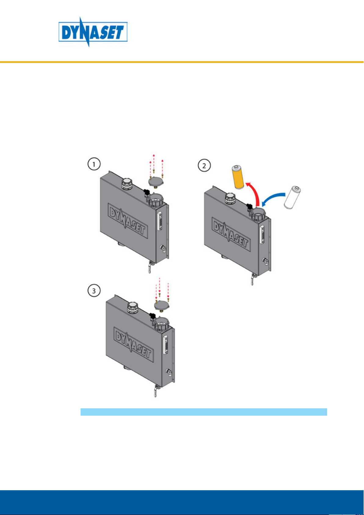
6.7. OIL FILTER CHANGE
Shut down the HVG system, depressurise the system and make sure it can’t be
started accidentally.
3. Close the drain and fill
the tank with new oil.
4. Screw the cap back on
Picture 49: Oil filter change
1. Remove the filter cap
2. Replace the old filter
with new one
3. Close the filter cap
Dynaset Oy | Menotie 3, 33470 Ylöjärvi | puh. 03 3488 200 | info@dynaset.com | www.dynaset.com
53

6.8. TROUBLESHOOTING
Performing the maintenance tasks requires a qualified hydraulic mechanic or/
and electrician. Please, contact DYNASET authorized workshop or dealer for more
maintenance information.
FAILURE REASON CORRECTIVE ACTION
Too low generator rotation
speed
VARIABLE HYDRAULIC GENERATOR SYSTEMS
MAINTENANCE
Check whether the hydraulic ow
and pressure are sucient. Adjust
the pressure if necessary. If the
adjustment won’t help check if there
is a clog in the LS-line and clean the
LS-line.
Too high return line (T) pressure.
Check return oil pressure. Pressure
should be under 5 bar.
LOW OUTPUT VOLTAGE
AT NO LOAD
Excitation rectier’s failure
Poor contact in electric
system
Voltage failure
Voltage regulator’s failure
Insucient residual
magnetism
Check the hydraulic motor for possible
leakage. Replace motor if necessary.
Trace the failure and replace the
rectier.
Check all internal contacts and wirings
of the generator. Check and clean
brushes and slip ring.
Check and adjust the air gap of the
compound regulator. Replace if
broken (HGV 6.5/10 ).
Check and adjust or replace the
electronic regulator (HGV 12/15/20)
Check and adjust or replace the
compound regulator (HGV 6.5/10 ).
Check and adjust or replace the
electronic regulator.
Use external 12 V DC battery for 1 - 2
sec. to magnetise the rotor.
54
Dynaset Oy | Menotie 3, 33470 Ylöjärvi | puh. 03 3488 200 | info@dynaset.com | www.dynaset.com

VARIABLE HYDRAULIC GENERATOR SYSTEMS
MAINTENANCE
FAILURE REASON CORRECTIVE ACTION
The generator is being
overloaded
Too low rotation speed of
LOW OUTPUT VOLTAGE
AT LOAD
FAILURE REASON CORRECTIVE ACTION
the generator
Voltage regulator’s failure
Reduce the load and check the
current I (A) to ensure that the proper
load is being applied.
Hydraulic pressure insucient. Adjust
the hydraulic ow.
Hydraulic motor worn out. Replace
hydraulic motor.
Too high return line pressure. Check
return oil pressure. Pressure should be
under 5 bar.
Check and adjust or replace the
compound regulator (HGV 6.5/10).
Check and adjust or replace the
electronic regulator (HGV 12/15/20).
Check HGV’s hydraulics. Make
adjustments if necessary.
OUTPUT VOLTAGE
INSTABILITY
Instable rotation speed of
generator
Electronic voltage
regulator’s failure
Poor contact in electric
system
Check whether the hydraulic ow and
pressure are excessive. Adjust the ow
if necessary.
LS-line requires a 0,8 mm jet.
Check the hydraulic motor for possible
leakage. Replace motor if necessary.
Adjust stability of the regulator.
Replace if broken.
Check all internal contacts and wiring
of the generator. Check and clean
brushes and slip ring.
Dynaset Oy | Menotie 3, 33470 Ylöjärvi | puh. 03 3488 200 | info@dynaset.com | www.dynaset.com
55

VARIABLE HYDRAULIC GENERATOR SYSTEMS
MAINTENANCE
FAILURE REASON CORRECTIVE ACTION
A MILD ELECTRIC
SHOCK FROM HGV
OIL LEVEL TOO LOW
(LIGHT TURNS ON)
OIL TEMPERATURE
TOO HIGH
Poor hydraulic generator
grounding
Oil level has declined due to
a leakakge in the system
Oil temperature has risen
too high due to a failed
cooling system
Too high pressure in the
system (oil runs through the
pressure release valve)
Clogged cooling system
Grounding cable is not installed.
Poor grounding cable or frame
contact.
Stop the system and the base
machine’s engine.
Check the hydraulic system’s hoses/
pipes/connections for leakages
repair the leakage.
Stop working with the HGV but leave
the system running.
Check the cooling system if it is
working (fan is spinning) or if it is
dirty and clogged. BEWARE THE HOT
SURFACES!
Let the system cool down, clean
the cooling system and replace the
broken parts if needed.
56
Dynaset Oy | Menotie 3, 33470 Ylöjärvi | puh. 03 3488 200 | info@dynaset.com | www.dynaset.com

HYDRAULIC SCREW COMPRESSORS
7. MANUFACTURER’S LIMITED WARRANTY
1. Warranty coverage
All hydraulic accessories manufactured by DYNASET OY are subject to the terms
and conditions of this limited warranty. Products are warranted to the original
purchaser to be free from defects in materials or workmanship. Exclusions from
warranty are explained in item Exclusions from warranty.
2. Beginning of warranty period
Warranty period begins from the delivery date of the product. Delivery is
considered to be done on the date when installation has been accomplished or
purchaser has taken the product in use. Product is considered as taken in use at the
date when DYNASET OY has delivered the product to purchaser, unless separately
agreed otherwise by written agreement.
3. Warranty period
Warranty period is twenty four (24) months based on maximum of 2000 hours
usage during this time period. In cases where the system is provided complete with
certain special components (e.g. drive unit), those components are considered as
a subject to their manufacturer’s warranty.
WARRANTY
4. Warranty procedures
Immediately upon identifying a problem which purchaser believes to be a failure
subject to the product’s limited warranty, purchaser must contact primary to the
seller of the product. Contact must be made as soon as possible, latest thirty (30)
days after the problem was identified. Seller and/or manufacturer technical staff
determines the nature of the problem primarily by phone or e-mail. Purchaser
commits to give necessary information and to perform routine diagnostic
procedures in order to determine the nature of the problem and necessary
procedures.
5. Warranty repairs
If the product is found to be defective during the warranty period, DYNASET
OY will, at its option, either repair the product, author it to be repaired at its
authorized workshop or exchange the defective product. If the product must be
repaired elsewhere than premises of DYNASET OY or authorized workshop, all
costs excluded from this warranty (traveling and waiting hours, daily allowance,
traveling expenses and uninstallation/reinstallation costs) will be charged from
the purchaser. If the problem is not covered by this limited warranty, DYNASET OY
has the right to charge purchaser of troubleshooting and repairing.
6. Delivery terms of warranty repair
If the product is found possible to be defective under this limited warranty and it
needs to be repaired, DYNASET OY gives Warranty Return Number (WRN). Items
being returned must be shipped, at the purchaser’s cost, adequately packed for
shipment, to the DYNASET OY or to other location authored by DYNASET OY.
Shipment documents must contain:
• Purchaser’s name and contact information
• Receipt of original purchase
• WRN code
• Problem description
Dynaset Oy | Menotie 3, FI-33470 Ylöjärvi, Finland | tel: +358 3 3488 200 | info@dynaset.com | www.dynaset.com
57

HYDRAULIC SCREW COMPRESSORS
WARRANTY
7. Warranty of repaired product
Warranty period of the product repaired under this limited warranty continues to
the end of original warranty period.
8. Exclusions from warranty
This warranty shall not apply to:
• Failures due to normal wear and tear, improper installation, misuse, abuse,
negligence, purchaser selection of improper product to intended use, accident,
improper filtration of hydraulic oil or intake water or lack of maintenance.
• Cost of maintenance, adjustments, installation or startup.
• Coating, hydraulic oil, quick couplings and interconnection hoses (internal or
external to system assemblies).
• Products altered or modified in a manner not authorized by DYNASET OY in
writing.
• Products which have been repaired during warranty period by others than
DYNASET OY or its authorized workshop.
• Costs of any other damage or loss, whether direct, indirect, incidental, special
or consequential, arising out of the use of, or the inability to use, the product.
• Telephone or other communications expense.
• Product that is used in exceptional conditions, considered to cause excessive
wear and tear.
• Faults caused by nature phenomenon’s like flood, thunder, etc.
© DYNASET OY, all rights reserved
58
Dynaset Oy | Menotie 3, FI-33470 Ylöjärvi, Finland | tel: +358 3 3488 200 | info@dynaset.com | www.dynaset.com

8. PRODUCT DISPOSAL
Dispose and recycle all DYNASET products and their packaging environmentally
responsible way.
Do not dispose used oils, electrical components, batteries or any other hazardous
waste with normal waste. They are harmful for the environment and can be
recycled for re-use.
Contact your local waste recycling facility for more information about recycling
hazardous waste.
NOTE!
Always act according to the waste legislation, regulations and
recommendations in waste disposal and waste recycling issued by your
local authorities.
HYDRAULIC SCREW COMPRESSORS
PRODUCT DISPOSAL
Dynaset Oy | Menotie 3, FI-33470 Ylöjärvi, Finland | tel: +358 3 3488 200 | info@dynaset.com | www.dynaset.com
59

HYDRAULIC SCREW COMPRESSORS
PRODUCT DISPOSAL
60
Dynaset Oy | Menotie 3, FI-33470 Ylöjärvi, Finland | tel: +358 3 3488 200 | info@dynaset.com | www.dynaset.com

VARIABLE HYDRAULIC GENERATOR SYSTEMS
DECLARATION OF CONFORMITY
9. DECLARATION OF CONFORMITY
We hereby declare that the design and manufacture of the product stated below
are in conformity with the provisions of the European Parliament and Councils on
the harmonization of the laws of Member States on the safety of machine’s.
Machine directive 2006/42/EC
LVD directive 2014/35/EU
EMC directive 2014/30/EU
RoHS directive 2011/65/EU
Applied conformity standards:
CEN EN ISO 4413: EN ISO 4413:2010 Hydraulic fluid power -
General rules and safety requirements for systems and their
components.
EN60204-1 Safety of machinery – Electrical equipment of
machine’s.
Manufacturer: DYNASET Oy
Menotie 3, FI-33470 Ylöjärvi, Finland
Product group: VARIABLE HYDRAULIC GENERATOR SYSTEMS
Product: HGV Basic Variable Hydraulic Generator System
HGV Power Box Variable Hydraulic Generator System
If the device has been modified by someone other than the manufacturer or
without the manufacturer’s permission, this declaration is not valid.
Timo Nieminen
R&D Manager
Ylöjärvi, Suomi, 20.04.2016
Dynaset Oy | Menotie 3, 33470 Ylöjärvi | puh. 03 3488 200 | info@dynaset.com | www.dynaset.com
61

VARIABLE HYDRAULIC GENERATOR SYSTEMS
DECLARATION OF CONFORMITY
62
Dynaset Oy | Menotie 3, 33470 Ylöjärvi | puh. 03 3488 200 | info@dynaset.com | www.dynaset.com

VARIABLE HYDRAULIC GENERATOR SYSTEMS
10. TECHNICAL SPECIFICATIONS
TECHNICAL SPECIFICATIONS
STANDARD MODELS
OUTPUT CHARACTERISTICS
Output Power max. kVA 3,5 6,5 10 15 20
Power factor kW / cos φ 3,5 / 1,0 5,2 / 0,8 8,0 / 0,8 12 / 0,8 16 / 0,8
Output Voltage
Nominal Current
Frequency Hz 50 50 50 50 50
Sockets
(1 phase / 3 phase / cable K)
Pump speed** RPM
HYDRAULIC POWER
Pressure max. bar 210 210 210 210 210
HYDRAULIC CONNECTION
Pressure line P 3/4”
Suction line S 1 1/2”
LS-Line LS 1/4”
Drain line Dr 3/8”
HYDRAULIC FLUID REQUIREMENTS
Viscosity cSt 10-200 / optimum 25-35
Temperature °C(°F) max. 70 (158) ***
Filter ratio μm 25 or better
Cleanliness level ISO 4406 19/17/14
OVERALL DIMENSIONS
Box size S/M S S S M M
Length mm (in) 884 (34.8) 884 (34.8) 884 (34.8) 960 (37.8) 960 (37.8)
Width mm (in) 502 (19.8) 502 (19.8) 502 (19.8) 702 (27.6) 702 (27.6)
Height mm (in) 490 (19.3) 490 (19.3) 490 (19.3) 478 (18.8) 478 (18.8)
Weight kg (lbs) 60 - 240 **** 80 - 350****
1 phase* 230 VAC 230 VAC 230 VAC 230 VAC 230 VAC
3 phase - 400 VAC 400 VAC 400 VAC 400 VAC
1 phase 15,2 14,1 21,7 32,6 43,5
3 phase - 9,4 14,4 21,7 28,9
IP 23 23 23 23 23
HGV
Power
Box
3,5
2 / - / - 2 /1 / - 2 /1 / - 2 /1 / - 2 /1 / -
500 4000
HGV
Power
Box
6,5
750 4000
HGV
Power
Box
10
850 4000
HGV
Power
Box
15
700 3000
HGV
Power
Box
20
650 3000
* Nominall current (1~phase / 3~phase) /phase. Must not exceed maximum load.
** High speed pump model available by request.
*** Ref. to the hydraulic fluid in chapter 6.2.
**** Weight variates with the selected components in the system.
Dynaset Oy | Menotie 3, 33470 Ylöjärvi | puh. 03 3488 200 | info@dynaset.com | www.dynaset.com
63

VARIABLE HYDRAULIC GENERATOR SYSTEMS
TECHNICAL SPECIFICATIONS
STANDARD MODELS
OUTPUT CHARACTERISTICS
Output Power max. kVA 3,5 6,5 10 10
Power factor kW / cos φ 3,5 / 1,0 5,2 / 0,8 8,0 / 0,8 8,0 / 0,8
Output Voltage
Nominal Current
Frequency Hz 50 50 50 50
Sockets
(1 phase / 3 phase / cable K)
Pump speed** RPM 500 - 4000 750 - 4000 850 - 4000 700 - 3000
HYDRAULIC POWER
Pressure max. bar 210 210 210 210
GENERATOR HYDRAULIC CONNECTIONS
Pressure line P BSP 1/2”
Return line T BSP 1/2”
Drain line Dr 06L - (M12x1,5 Male)
HYDRAULIC FLUID REQUIREMENTS
Viscosity cSt 10-200 / optimum 25-35
Temperature °C(°F) max. 70 (158) ***
Filter ratio μm 25 or better
1 phase* 230 VAC 230 VAC 230 VAC 230 VAC
3 phase - 400 VAC 400 VAC 400 VAC
1 phase 15,2 14,1 21,7 21,7
3 phase - 9,4 14,4 14,4
IP 23 23 23 23
HGV
Basic
3,5
2 / - / - 2 /1 / - 2 /1 / - 2 /1 / -
HGV
Basic
6,5
HGV
Basic
10
HGV
Basic
10
* Nominall current (1~phase / 3~phase) /phase. Must not exceed maximum load.
** High speed pump model available by request.
*** Ref. to the hydraulic fluid in chapter 6.2.
64
Dynaset Oy | Menotie 3, 33470 Ylöjärvi | puh. 03 3488 200 | info@dynaset.com | www.dynaset.com

VARIABLE HYDRAULIC GENERATOR SYSTEMS
TECHNICAL SPECIFICATIONS
STANDARD MODELS
OUTPUT CHARACTERISTICS
Output Power max. kVA 12 15 20
Power factor kW / cos φ 9,6 / 0,8 12 / 0,8 16 / 0,8
Output Voltage
Nominal Current
Frequency Hz 50 50 50
Sockets
(1 phase / 3 phase / cable K)
Pump speed** RPM 800 - 3000 700 - 3000 650 - 3000
HYDRAULIC POWER
Pressure max. bar 210 210 210
GENERATOR HYDRAULIC CONNECTIONS
Pressure line P BSP 1/2”
Return line T BSP 1/2”
Drain line Dr BSP 3/4”
HYDRAULIC FLUID REQUIREMENTS
Viscosity cSt 10-200 / optimum 25-35
Temperature °C(°F) max. 70 (158) ***
Filter ratio μm 25 or better
1 phase* 230 VAC 230 VAC 230 VAC
3 phase 400 VAC 400 VAC 400 VAC
1 phase 26,1 32,6 43,5
3 phase 17,3 21,7 28,9
IP 23 23 23
HGV
Basic
12
2 / 1 / - 2 /2 / - 2 /2 / -
HGV
Basic
15
HGV
Basic
20
* Nominall current (1~phase / 3~phase) /phase. Must not exceed maximum load.
** High speed pump model available by request.
*** Ref. to the hydraulic fluid in chapter 6.2.
Dynaset Oy | Menotie 3, 33470 Ylöjärvi | puh. 03 3488 200 | info@dynaset.com | www.dynaset.com
65

VARIABLE HYDRAULIC GENERATOR SYSTEMS
TECHNICAL SPECIFICATIONS
66
Dynaset Oy | Menotie 3, 33470 Ylöjärvi | puh. 03 3488 200 | info@dynaset.com | www.dynaset.com

© DYNASET OY, all rights reserved

Menotie 3
FI-33470 Ylöjärvi, Finland
tel: +358 3 3488 200
info@DYNASET.com
ELECTRICITY
HG Hydraulic Generator
HGV POWER BOX Variable Hydraulic Generator System
HGV Variable Hydraulic Generator System
HWG Hydraulic Welding Generator
HGG Hydraulic Ground Power Generator
HIGH PRESSURE WATER
HPW Hydraulic High Pressure Water Pump
HPW Hydraulic Power Washer
KPL High Pressure Street Washing Unit
HPW-DUST High Pressure Dust Suppression System
PPL High Pressure Pipe Cleaning Unit
HPW-FIRE High Pressure Fireghting System
FP Fire Fighting Piercing Kit
HDF Hydraulic Drilling Fluid Pump
JPL High Pressure Bin Washing System
HSP Hydraulic Submersible Pump
MAGNET POWER
HMG PRO Hydraulic Magnet Generator
MAG Lift Magnet
HMAG PRO Hydraulic Magnet
VIBRATION
HVB Hydraulic Vibration Pump
HVD Hydraulic Directional Vibra
HVC Hydraulic Vibration Compactor
HRC Hydraulic Reversal Cylinder
POWER BOOSTING
HPI Hydraulic Pressure Intensier
HPI-C Hydraulic Pressure Intensier for Cylinder
COMPRESSED AIR
HK Hydraulic Piston Compressor
HKL Hydraulic Rotary Vane Compressor
HKR Hydraulic Screw Compressor
www.DYNASET.com
KNOW-HOW
Hydraulic Power Take-o (PTO)
Hydraulic Power Unit Technology
HEU Hydraulic Expansion Unit
HRU Hydraulic Rescue Unis
De-Icing Technology
Installation Valves
HHK Hydraulic Grinder
HV/HVY Hydraulic Winch / Winch Unit
 Loading...