

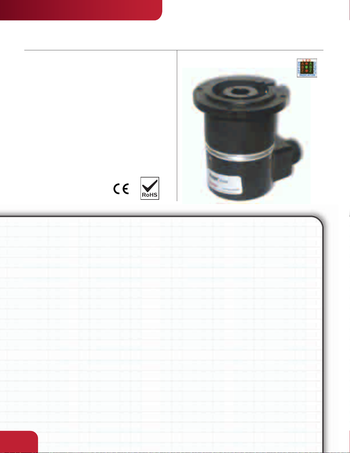
INDUSTRIAL DUTY
SERIES HC26
Integral Coupling Encoder
Key Features
• High 5000PPR Resolution Available
• Integral Coupling and Flange Provide
Thermal and Electrical Isolation
• Field Replaceable Coupling
Dynapar
™
brand
SPECIFICATIONS
STANDARD OPERATING CHARACTERISTICS
Code: Incremental
Resolution: 3000 to 5000 PPR (pulses/
revolution)
Accuracy: (worst case any edge to any other
edge) ±10.8°/PPR
Format: Two channel quadrature (AB) with
optional Index (Z) and complementary outputs
Phase Sense: A leads B for CW or CCW shaft
rotation as viewed from the shaft end of the
encoder; see Ordering Information
Quadrature Phasing: 90° ± 25° electrical
Symmetry: 180° ± 25° electrical
Index: 90° ± 25° electrical (gated with B low)
Waveforms: Squarewave with rise and fall times
less than 1 microsecond into a load capacitance
of 1000 pf
ELECTRICAL
Input Power:
4.5 min. to 26 VDC max. at 80 mA max., not
including output loads
Outputs:
7273 Open Collector: 30 VDC max., 40 mA sink
max.
7272 Push-Pull and Differential Line Driver: 40 mA
sink or source
Frequency Response: 250 kHz min.
Electrical Protection: Overvoltage, reverse voltage
and output short circuit protected
Noise Immunity: Tested to EN61326 (Industrial)
for Electro Static Discharge, Radio Frequency
Interference, Electrical Fast Transients, Conducted
and Magnetic Interference
Mating Connector:
7 pin, style MS3106A-16S-1S (MCN-N5);
10 pin, style MS3106A-18-1S (MCN-N6)
5 pin, style M12: Cable with connector available
8 pin, style M12: Cable with connector available
MECHANICAL
Shafts coupling: accepts 1/4", 3/8" and 1/2"
motor or machinery shafts
Shafts alignment: 0.002" max. TIR runout;
0.005" max. radial offset; 3° max. angular
Shaft Speed: 10,000 RPM max.
Starting Torque: (max at 25 °C) 1.0 oz-in
Moment of Inertia: 4.3 x 10⁻⁴ oz–in–sec
ENVIRONMENTAL
Operating Temperature:
Standard: 0 to +70 °C;
Extended: –40 to +85 °C
Storage Temperature: –40 to +90 °C
Shock: 50 G’s for 11 milliseconds duration
Vibration: 5 to 2000 Hz at 20 G’s
Humidity: to 98% without condensation
Enclosure Rating: NEMA12/IP54 (dirt tight,
splashproof)
2
2.58
by
INDUSTRIAL DUTY
SERIES HC26
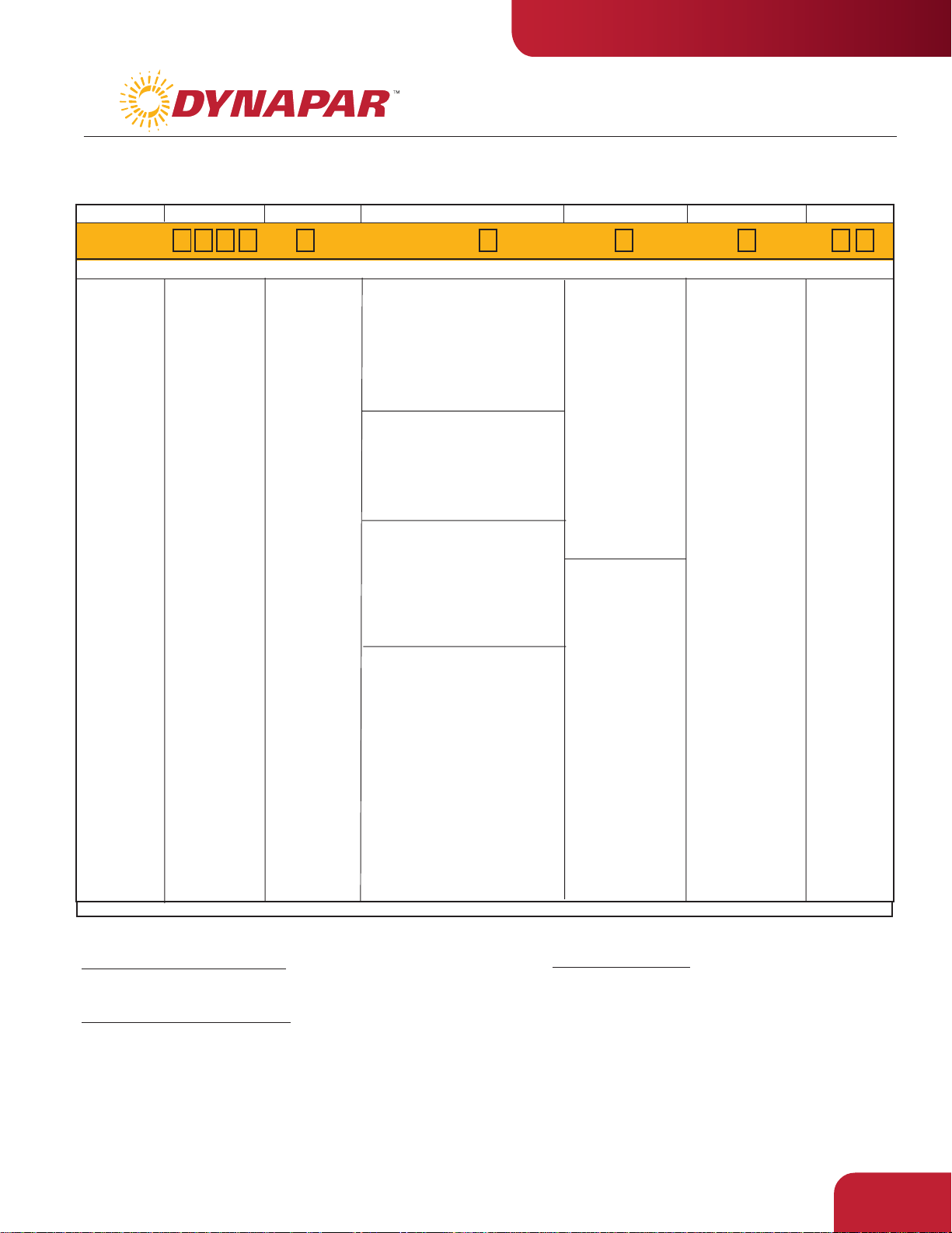
Ordering Information
To order, complete the model number with code numbers from the table below:
Code 1: Model
HC526
HC526
Size 25 Enclosed
with Integral
Coupling
and Flange
Adapter
Code 2: PPR
3000
3600
4096
5000
3,000
3,600
4,096
5,000
Code 3: Mechanical
A Flange Adapter
with Pilot
B Flange Adapter
without Pilot
C Flange Adapter
for NEMA Size
42 Motors
Code 4: Output
Ordering Information
7 Pin Connector or Cable
0 Single Ended, no Index, Format A, Table 1
1 Single Ended, with Index, Format A, Table 1
4 Single Ended, with Index, Format B, Table 1
A Single Ended, with Index, Format C, Table 1
C Single Ended, no Index, Format C, Table 1
G Single Ended, with Index, Format D, Table 1
10 Pin Connector or Cable
2 Differential, no Index, Format A, Table 2
3 Differential, with Index, Format A, Table 2
5 Differential, with Index, Format B, Table 2
B Differential, with Index Format C, Table 2
D Differential, no Index, Format C, Table 2
5 Pin M12 Connector
H Single ended, no index, Format A, Table 4
J Single ended, with index, Format A, Table 4
K Single ended, with index, Format B, Table 4
L Single ended, with index, Format C, Table 4
M Single ended, no index, Format C, Table 4
N Single ended, with index, Format D, Table 4
8 Pin M12 Connector
P Single ended, no index, Format A, Table 5
Q Single ended, with index, Format A, Table 5
R Single ended, with index, Format B, Table 5
S Single ended, with index, Format C, Table 5
T Single ended, no index, Format C, Table 5
U Single ended, with index, Format D, Table 5
V Differential, no index, Format A, Table 6
W Differential, with index, Format A, Table 6
X Differential, with index, Format B, Table 6
Y Differential, with index, Format C, Table 6
Z Differential, no index, Format C, Table 6
Code 5: Electrical
A Same as "0"
B Same as "1"
C Same as "2"
D Same as "3"
0 5-26V in; 5-26V
Open Collector
with 2.2kΩ
Pullup out
1 5-26V in;
5-26V Open
Collector out
2 5-26V in; 5V
Totem Pole
out
3 5-26V in; 5V
Differential
Line Driver out
(7272)
4 5-26V in;
5-26V
Differential
Line Driver out
(7272)
with extend.
temp range
with extend.
temp range
with extend.
temp range
with extend.
temp range
E Same as "4"
with extend.
temp range
Code 6: Termination
0 End Mount
Connector
1 Side Mount
Connector
2 18" Cable, Side
3 3' Cable, Side
4 6' Cable, Side
5 10' Cable, Side
6 15' Cable, Side
Code 7: Options
available when
Code 4 is 0 thru
G, and Code 6 is
0 or 1:
PS LED Output
Indicator
CPLX1250375 Flexible Coupling 3/8" to 1/4", 3/8" or 1/2"
10 foot Cable Assemblies with MS Connector
1400431-0010 7 Pin MS, Cable Assy. For Use with Single Ended w/Index Outputs
1400635-0010 10 Pin MS, Cable Assy. For Use with Differential Line Driver with Index Outputs
15 foot Cable Assemblies with M12 Connector
112859-0015 5 Pin M12, Cable Assy. For Use with Single Ended Outputs
112860-0015 8 Pin M12, Cable Assy. For Use with Single Ended Outputs
112860-0015 8 Pin M12, Cable Assy. For Use with Differential Line Driver Outputs
Mating Connectors (no cable)
7 pin, style MS3106A-16S-1S (MCN-N5)
10 pin, style MS3106A-18-1S (MCN-N6)
2.59
INDUSTRIAL DUTY
SERIES HC26
Dynapar
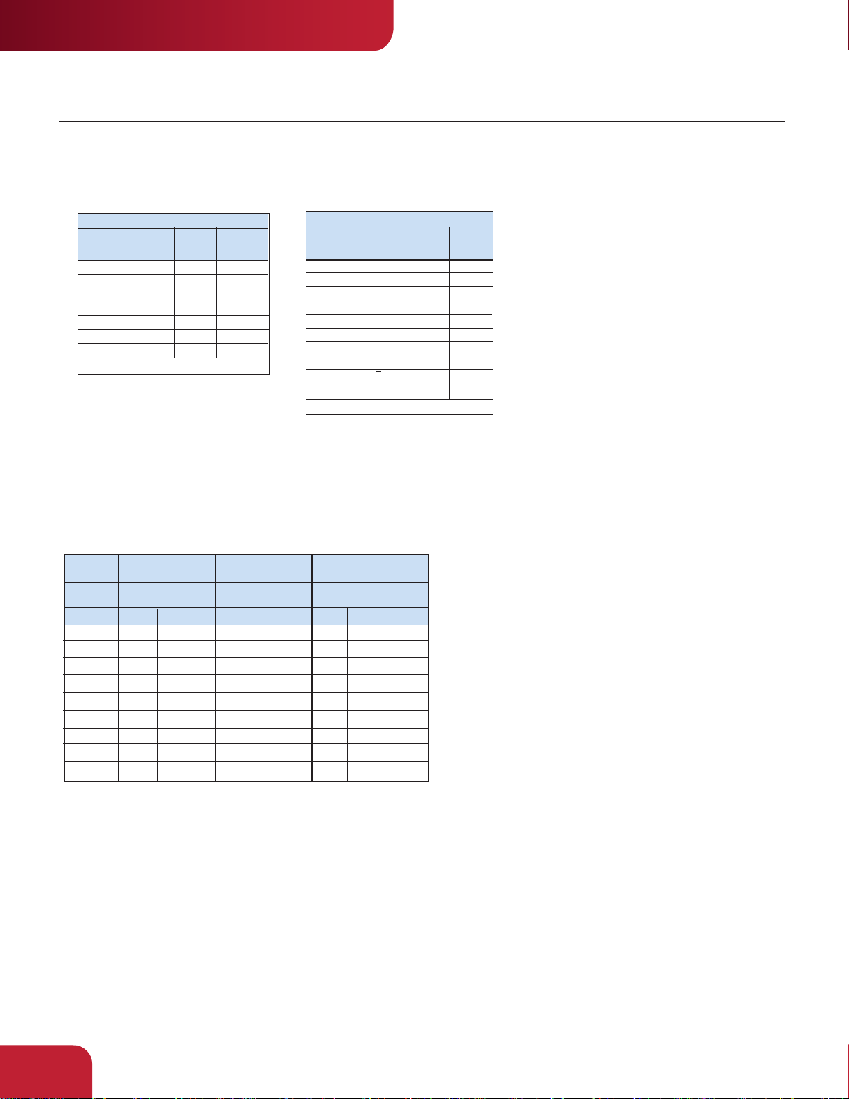
ELECTRICAL CONNECTIONS
Prewired Cable or Accessory Cables with 7 or 10 Pin MS Connector - when Code 4= 0 to 5, or A, B, C, D or G
Note: Wire color codes are referenced here for models that are specified with pre-wired cable. Connector/cables are described
in the Encoder Accessories section of this catalog and color-coding information is provided here for reference.
Table 1 – Single Ended
Wire
Function
Pin (If Used)
A Signal A BRN
B Signal B ORN
C Signal Z YEL
D Power Source RED
E No Connection —
F Common BLK
G Case GRN
*Cable Accessory: P/N 14004310010
Cable Configuration: PVC jacket, 105 °C rated, overall foil shield; 3 twisted
pairs 26 AWG (output signals), plus 2 twisted pairs 24 AWG (input power)
Color
Code
Cable*
Accessory
Color Code
RED
BLUE
YEL
WHT
GRN
BLK
SHIELD
Pin (If Used)
A Signal A BRN
B Signal B ORN
C Signal Z YEL
D Power Source RED
E No Connection —
F Common BLK
G Case GRN
H Signal A BRN/WH
I Signal B ORN/WH
J Signal Z YEL/WH
Table 2 – Differential
Function
*Cable Accessory: P/N
Wire
Accessory
Color
Color Code
Code
14006350010
Cable*
BRN
ORN
YEL
RED
—
BLK
GRN
BRN/WH
ORN/WH
YEL/WH
™
brand
Connector pin numbers and cable assembly wire color information is
provided here for reference.
Table 4 Table 5 Table 6
5 Pin Single Ended 8 Pin Single Ended 8 Pin Differential
Encoder
Function Cable # 112859-* Cable # 112860-* Cable # 112860-*
Sig. A
Sig. B
†Sig. Z
Power +V
Com
Sig. –A
Sig. –B
†Sig. –Z
Cable Configuration: PVC jacket, 105 °C rated, overall foil
shield; 24 AWG conductors, minimum
*Note: Standard cable length is 10 feet but may be ordered in any length in
†Note: Index not provided on all models. See ordering information
See “Accessories” Section for Connectors and Cable Assemblies Ordering Information
Pin Wire Color Pin Wire Color Pin Wire Color
4
2
5
1
3
–
–
–
5 foot increment. For example, -0020 is a 20 foot cable.
BLK
WHT
GRY
BRN
BLU
–
–
–
1
BRN
4
ORG
6
YEL
2
RED
7
BLK
–
–
–
–
–
–
1
4
6
2
7
3
5
8
BRN
ORG
YEL
RED
BLK
BRN/WHT
ORG/WHT
YEL/WHT
2.60

by
DIMENSIONS
A: Flange with Pilot B: Flange without Pilot C: NEMA 42 Flange
MOUNTING SURFACE
4 HOLES, .181 DIA.
EQUALLY SPACED 90°
APART ON A 2.952" DIA. B.C.
.120
INDUSTRIAL DUTY
SERIES HC26
Code 3: Mechanical
.27
MOUNTING SURFACE
4 HOLES, .181 DIA.
EQUALLY SPACED 90°
APART ON A 2.952" DIA. B.C.
.27
MOUNTING SURFACE
4 HOLES, .181 DIA.
EQUALLY SPACED 90°
APART ON A 2.952" DIA. B.C.
.200
2.439
2.436
1.94
3.25
REF.
3.940 MAX
Mating shaft lengths: Typically: 0.5" max. available into the coupling as measured from the A/B mounting surface.
1.3" max. available into the coupling as measured from the C mounting surface.
3.25
1.94
REF.
3.940 MAX
Code 4: Output
0 - 3: Format A G: Format D6 - D: Format C4 - 5: Format B
CCW
A
B
Z
CCW
A
B
Z
CW
A
B
Z
Code 6: Termination
0: End MS Connector 1: Side MS Connector 2 - A: Side Cable
When Code 5 is 0 to 5 or A to G When Code 5 is 0 to 5 or A to G
0.91"
Max.
2.18"
2.76"
Max.
1.93"
2.18"
3.25
1.32"
1.94
REF.
0.73
4.740 MAX
CCW
A
B
Z
1.78"
0: End M12 Connector
When Code 5 is H to Z
0.58"
2.18"
1: Side M12 Connector
When Code 5 is H to Z
0.58"
1.75"
1.93"
2.61
 Loading...