

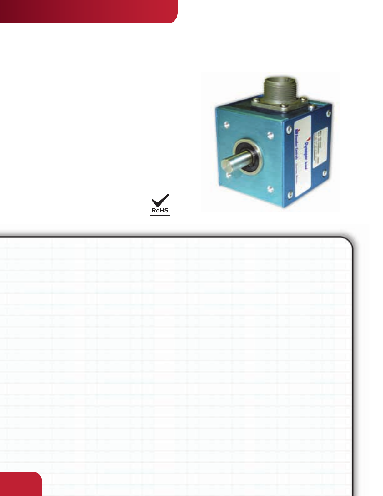
INDUSTRIAL DUTY
SERIES 22
“QUBE” Encoder
Key Features
• Economical Anodized Housing
• Dual Shaft Output Option
• Up to 1270PPR with Optional Index
Dynapar
™
brand
SPECIFICATIONS
STANDARD OPERATING CHARACTERISTICS
Code: Incremental
Resolution: 1 to 1270 PPR (pulses/revolution)
Accuracy: (Worst case any edge to any other edge)
±2.5 arc-min.
Format: Two channel quadrature (AB) with
optional Index (Z) and complementary outputs
Phase Sense: A leads B for CW shaft rotation as
viewed from the shaft end of the encoder farthest
from the connector or cable
Quadrature Phasing: 90° ± 18° electrical
Symmetry: 180° ± 18° electrical
Index: 225° ± 90° electrical (active high)
Waveforms: Squarewave with rise and fall times
less than 1 microsecond into a load capacitance of
1000 pf
ELECTRICAL
Input Power:
4.5 min. to 26 VDC max. at 110 mA max., not
including output loads
Outputs:
7273 Open Collector: 30 VDC max., 40 mA sink
max.
7272 Push-Pull and Differential Line Driver: 40 mA
sink or source
Frequency Response: 120 kHz min. data, 50 kHz
min. Index
CONNECTIONS
Mating Connector:
6 pin, style MS3106A-14S-6S (MCN-N4)
7 pin, style MS3106A-16S-1S (MCN-N5)
5 pin, style M12: Cable with connector available
8 pin, style M12: Cable with connector available
Mechanical
Shaft Loading: 40 lbs. radial, 30 lbs. axial
Shaft Speed: 6,000 RPM max.
Shaft Tolerance: Nominal -0.0003"/-0.0007"
Starting Torque: 2.5 oz-in max.
Moment of Inertia: 1.3 x 10⁻⁴ oz–in–sec
Weight: 14 oz. max.
ENVIRONMENTAL
Operating Temperature: 0 to +70 °C;
Storage Temperature: –40 to +90 °C
2
2.04
by
INDUSTRIAL DUTY
SERIES 22
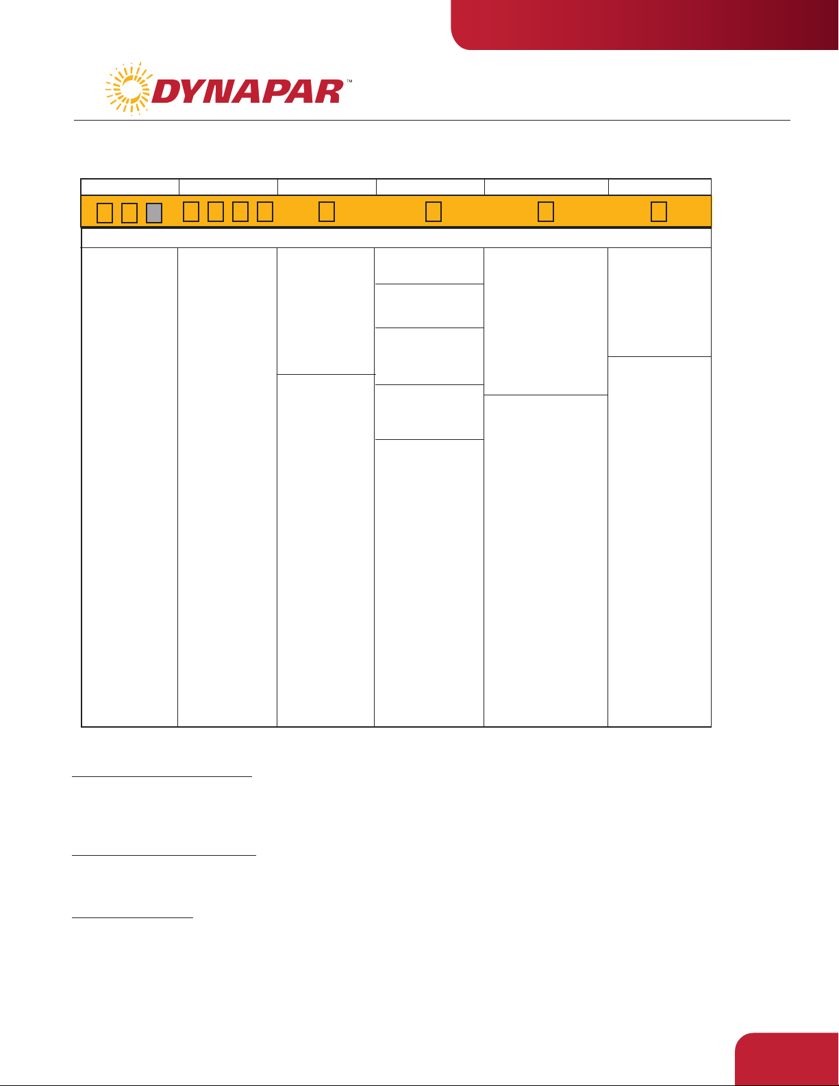
Ordering Information
To order, complete the model number with code numbers from the table below:
Code 1: Model
22 Qube
Encoder,
Bidirectional
22M Metric Qube
Encoder,
Bidirectional
Code 2: Pulses/Rev Code 3: Mechanical
Ordering Information
0001
0010
0050
0060
0100
0120
0125
0150
0180
0192
0200
0250
0256
0300
0360
0400
0480
0500
0512
0600
0720
0800
0900
1000
1024
1200
1250
1270
0 3/8" Double
Ended Shaft
1 3/8" Single
Ended Shaft
2 1/4" Double
Ended Shaft
3 1/4" Single
Ended Shaft
available when Code
1 = 22M:
4 6mm Double
Ended Shaft
5 6mm Single
Ended Shaft
Code 4: Output
0 Single Ended, Table 1
2 Differential, Table 2
available only when
code 6 is 0:
4 Differential, Table 4
available only when
Code 1 is 22 or 22M:
1 Single Ended, with
Index, Table 3
available only when
Code 6 is 1 to 5:
3 Differential, with
Index, Table 5
available only when
Code 6 is 6:
5 5 pin M12 connector,
single ended, no
index, Table 6
6 5 pin M12 connector,
single ended, with
index, Table 6
7 8 pin M12 connector,
single ended, no
index, Table 7
8 8 pin M12 connector,
single ended, with
index, Table 7
9 8 pin M12 connector,
differential, no index,
Table 8
A 8 pin M12 connector,
differential, with
index, Table 8
Code 5: Electrical
available when Code4 =
0, 1, 5, 6, 7 or 8:
0 5-26 VDC in, 5-26
VDC Open Collector
w/2.2k pull-ups out
1 5-26 VDC in, 5-26
VDC Open Collector
w/o pull-up out
2 5-26 VDC in, 5V
Totem Pole out
available when Code4 =
2, 3, 4, 9 or A:
3 5-26 VDC in, 5V
Line Driver out
4 5-26 VDC in, 5-26
VDC CMOS Line
Driver
Code 6: Termination
0 MS Connector
1 18" Cable
2 3' Cable
3 6' Cable
4 10' Cable
5 15' Cable
available when Code 4
= 5, 6, 7, 8, 9 or A:
6 M12 Connector
10 foot Cable Assemblies with MS Connector
1400607-0010 6 Pin MS, Cable Assy. For Use with Single Ended Outputs
108241-0010 6 Pin MS, Cable Assy. For Use with Single Ended w/Index Outputs
1400664-0010 6 Pin MS, Cable Assy. For Use with Differential Line Driver Outputs
1400431-0010 7 Pin MS, Cable Assy. For Use with Differential Line Driver Outputs
15 foot Cable Assemblies with M12 Connector
112859-0015 5 Pin M12, Cable Assy. For Use with Single Ended Outputs
112860-0015 8 Pin M12, Cable Assy. For Use with Single Ended Outputs
112860-0015 8 Pin M12, Cable Assy. For Use with Differential Line Driver Outputs
Mating Connectors (no cable)
6 pin, style MS3106A-14S-6S (MCN-N4)
7 pin, s
tyle MS3106A-16S-1S (MCN-N5)
2.05

INDUSTRIAL DUTY
SERIES 22
ELECTRICAL CONNECTIONS
MS Connector Accessory Cables - when Code 4= 0 to 4
Table 1 – Current Sink Output
Pin
A
B
C
D
E
F
Function
Common
Power Source
Case (Ground)
Signal A
Signal B
Supply Common
Wire Color
Code
BLK
RED
GRN/BLK
GRN
ORN
BLK
Cable Acc’y
#14006070010
Color Code
BLK
RED
GRN
BRN
ORN
BLK
Table 3 – Current Sink Output w/Marker
Pin Function
Common
A
Power Source
B
Signal Z
C
Signal A
D
Signal B
E
Common
F
Wire Color
Code
BLK
RED
WHT
GRN
ORN
BLK
Cable Acc’y
#108241-0010
Color Code
BLK
RED
GRN
BRN
ORN
BLK
Cable Configuration: PVC jacket, 105 °C rated, overall foil shield; 3 twisted pairs 26 AWG (output signals), plus
2 twisted pairs 24 AWG (input power)
Table 2 – 7 Pin Line Driver Output
A
B
Wire Color
Code
GRN
ORN
RED/BLK
RED
WHT/BLK
BLK
GRN/BLK
Pin
A
B
C
D
E
F
G
Function
Signal A
Signal B
Signal
Power Source
Signal
Common
Case (Ground)
Table 4 – 6-Pin Line Driver
A
B
Wire Color
Code
BLK
RED
GRN
RED/BLK
ORN
WHT/BLK
Pin
A
B
C
D
E
F
Function
Common
Power Source
Signal A
Signal
Signal B
Signal
Cable Acc’y
#14004310010
Color Code
Cable Acc’y
#14006640010
Color Code
BLK
RED
BRN
BRN/WHT
ORN
ORN/WHT
Dynapar
RED
BLU
YEL
WHT
GRN
BLK
Table 5 – Cable termination Line
Driver Output with Marker
Function
Signal A
Signal B
Signal Z
Power Source
Supply Common
Case (Ground)
Signal
Signal
Signal
A
B
Z
™
brand
Wire Color
Code
GRN
ORN
WHT
RED
BLK
GRN/BLK
RED/BLK
WHT/BLK
BLU
5 & 8 Pin M12 Accessory Cables - when Code 4= 5 to 9 and A
Connector pin numbers and cable assembly wire color information is
provided here for reference.
Table 6 Table 7 Table 8
5 Pin Single Ended 8 Pin Single Ended 8 Pin Differential
Encoder
Function Cable # 112859- Cable # 112860- Cable # 112860-
Sig. A
Sig. B
*Sig. Z
Power +V
Com
Sig. –A
Sig. –B
*Sig. –Z
* Index not provided on all models. See ordering information
Cable Configuration: PVC jacket, 105 °C rated, overall foil
shield; 24 AWG conductors, minimum
See “Accessories” Section for Connectors and Cable Assemblies Ordering Information
Pin Wire Color Pin Wire Color Pin Wire Color
4
2
5
1
3
–
–
–
BLK
WHT
GRY
BRN
BLU
–
–
–
1
BRN
4
ORG
6
YEL
2
RED
7
BLK
–
–
–
–
–
–
1
4
6
2
7
3
5
8
BRN
ORG
YEL
RED
BLK
BRN/WHT
ORG/WHT
YEL/WHT
2.06

by
DIMENSIONS
MS Connector Models
Approximate Dimensions (in inches)
INDUSTRIAL DUTY
SERIES 22
Prewired Cable Models
2.250
MS CONNECTOR
.63
2.250
6-32 UNC-2B THREADS x .187 DEEP
ON 2.00 DIA. B.C., 4 HOLES ON 3
FACES (FRONT, REAR & BOTTOM).
FOR MODELS 22M ONLY: M3 x 0.5
THREADS x 5mm DEEP ON A 50.8mm
DIA. B.C. ON (3) FACES
M12 Connector Models
45°
TYP.
1.125
-6H
FLAT
.969
SHAFT
A .2497
B .3747
C 6 mm
.750
.06
2.250
.94
OPTIONAL
DOUBLE-ENDED
SHAFT
.81
.15
FLAT
.969
SHAFT
A .2497
B .3747
C 6 mm
.750
.06
2.250
.66
OPTIONAL
DOUBLE-ENDED
SHAFT
.81
.15
0.58
2.250
2.07
 Loading...