

Dynapac Svedala Demag EB 34 Series, Svedala Demag EB34V, Svedala Demag EB34TV Operation & Maintenance Manual

OPERATION
&
MAINTENANCE
Screed
Svedala Demag
EB 34
Keep this manual for future reference
Order number for this manual: D900981487
02-0508
270.................
275.................

VALUE
QUALITY
THE ORIGINA L
Your Authorized Dynapac Dealer:

Table of conten ts
V Preface ..................................................................................... 1
1 General safety instructions ........................................................................2
1.1 Acts, directives, accident prevention regulations .......................................2
1.2 Warning instructions ..................................................................................2
1.3 Prohibitive signs ............................................. ......... .......... ......... ......... .......4
1.4 Protective gear ...................................... ......... ......... .......... ......... ......... .......5
1.5 Environmental protection ...........................................................................6
1.6 Fire prevention ...........................................................................................6
1.7 Further instructions ....................................................................................7
A Correct use and application ...................................................1
B Description of the screed .......................................................1
1 Application .................................................................................................1
2 Assemblies .................................................................................................2
3 Safety ......................................................................................................... 4
3.1 Remaining risks at the screed ....................................................................4
4 Technical data ............................................................................................6
4.1 Dimensions ................................................................................................6
4.2 Weights ...................................................................................................... 6
4.3 Adjustment/equipment featur es ........................................ .........................7
4.4 Compacting system ...................................................................................7
4.5 Gas heater system .....................................................................................8
4.6 Electric heater EB 34 (V) ...........................................................................9
4.7 Electric heater EB 34 (TV) .........................................................................9
5 Location of instruction labels and type plates ..........................................10
5.1 Screed type plate (1) ................................................................................11
5.2 Liquefied gas system type plate (2) ......................................................12
C Transporta tion ... .......... ..... ......... .......... .......... ......... .......... .......1
1 Safety regulations for transportation ..........................................................1
2 Transporting the removed screed ..............................................................2
2.1 Transportation by crane ........................ ......... ......... .......... ......... ......... .......2
2.2 Transportation by fork-lift truck ..................................................................2
EB34_GBIVZ.fm 1-4
1

D Operation ................................................................................. 1
1 Notes regarding safety ...............................................................................1
2 Operation of the screed .............................................................................2
2.1 Extend/retract screed .................................................................................2
2.2 Adjusting the tamper (o) .............................................................................3
Adjusting the vibration ...........................................................................3
Tamper/vibration frequency displays (o) (6) / (7) ...................................4
3 Operation of the gas heater system with flame monitoring ........................5
3.1 Switch cabinet for screed heating system ......................... ......... ......... .......5
3.2 Gas supply diagram ...................................................................................7
3.3 General notes on the gas heater system ...................................................8
3.4 Connection and leak test ...........................................................................9
3.5 Commissioning and checking the heating system ...................................10
Ignition process ....................... .......... ......... ......... .......... ......... ......... .....10
3.6 Function of the flame monitoring system .................................................11
3.7 Setting the temperature level ...................................................................12
3.8 Switching off the heater ...........................................................................13
3.9 Exchanging the gas bottles ......................................................................13
4 Operating the electric heater ....................................................................14
4.1 Switch cabinet for screed heating system ......................... ......... ......... .....14
4.2 General information on the heating system .............................................16
4.3 Isolation monitor .......................................................................................17
Insulation faults ....................................................................................18
4.4 Commissioning and checking the heating system ...................................19
4.5 Temperature display, setting temperature level .......................................20
4.6 Operating the control and monitoring unit ................................................20
4.7 Temperature setting .................................................................................22
4.8 Fault messages ........................................................................................22
Fault codes ..........................................................................................22
4.9 Switching off the heating system .............................................................23
5 Malfunctions .............................................................................................24
5.1 Problems during paving ..........................................................................24
5.2 Malfunctions on the screed .....................................................................26
2
EB34_GBIVZ.fm 2-4

E Set-up and modification .........................................................1
1 Notes regarding safety ...............................................................................1
2 General assembly ......................................................................................2
2.1 Fitting screed to finisher .............................................................................2
2.2 Mounting the side shields ..........................................................................3
2.3 Hydraulic connections ....................................................... ......... ......... .......4
Position and designation of the connections: .......................................4
2.4 Electrical connections ................................................................................5
3 Extending the screed ..................................... ......... ............................ .......6
3.1 Removing side shields ...............................................................................6
3.2 Preparing extension parts ..........................................................................7
3.3 Removing tamper deflector plate ...............................................................7
3.4 Assembly of tamper drive shaft ..................................................................7
3.5 Fitting tamper deflector plate .....................................................................7
3.6 Fitting extension parts ................................................................................8
3.7 Fitting side shield to extension part ............................................................8
3.8 Screed heating system gas connections ...................................................9
3.9 Screed heater system electrical connections .............................................9
4 Settings .................................................................................................... 10
4.1 Setting extendable parts ..........................................................................10
Basic setting: .......................... .......... ......... ......... .......... ......... ......... .....10
Fine adjustment, setting during installing work: ...................................10
4.2 Setting tamper height ...............................................................................11
4.3 Setting tamper deflector plate: .................................................................11
4.4 Setting side shields ..................................................................................12
4.5 Setting crowing ........................................................................................12
4.6 Setting positioning angle ..........................................................................13
4.7 Positioning angle correction
Adjustment section / central section ........................................................13
EB34_GBIVZ.fm 3-4
3

F Maintenance ............................................................................1
1 Notes regarding safety ...............................................................................1
2 Maintenance intervals - screed in general .................................................2
3 Maintenance intervals - gas system ...........................................................3
4 Maintenance intervals - electric heating system ........................................4
5 Lubrication points .......................................................................................5
5.1 Guide tubes ................................................................................................5
5.2 Other lubricating and maintenance points .................................................6
6 Checkpoints ...............................................................................................7
6.1 Guides of the extendable parts ..................................................................7
Adjustment of guide tube play ...............................................................7
6.2 Cleaning the screed .............................. ......... ............................ ......... .......8
Emptying the tamper compartment ........................................................8
Cleaning side shield ...............................................................................9
6.3 Check / adjust tamper deflector plate ......................................................10
6.4 Hydraulic hoses ................................... ......... ......... .......... ......... ......... .....10
7 Gas system ..............................................................................................11
7.1 Spark plugs ..............................................................................................11
7.2 Adjusting the flame ..................................................................................12
7.3 Injectors of the gas heater system ...........................................................12
8 Electric heating system ............................................................................13
8.1 Check insulation monitoring .....................................................................13
Insulation faults ....................................................................................14
9 Lubricants ................................................................................................15
10 Electric fuses ............................................................................................16
10.1 Equipment with gas heating system ........................................................16
Fuses in the compacting element (1) control box ................................16
Fuse board (1) .....................................................................................16
11 Test certificates .............................................. ............................ ......... .....17
11.1 Electric screed heating system ................................................................17
4
EB34_GBIVZ.fm 4-4

VPreface
Safe operation of the machine requires specific knowledge that is imparted by the
present operati ng instruction s. The information is pr ovided in a concise, cle arly structured form. The individual chapters are arranged in alphabetical order and every
chapter starts with page 1. The individual pages are identified by the chapter letter
and the page number.
Example: Page B 2 is the second page of chapter B.
These operating instructions cover various machine options. Make sure that during
operation and m aintenance w ork the description appropriate to the machin e option is
used.
Safety instructions and important notes are identified by the following pictograms:
f
m
A
Precedes safety inst ructions that must be obser ved in orde r to p revent danger t o personnel.
Precedes notes that must be observed to prevent damage to equipment.
Precedes general notes and explanations.
t Used to indicate standard equipment.
o Used to indicate optional equipment.
In the interest of continu ed development, the man ufacturer reserve s the right to make
changes to the machine ( which will not, however, change the essential features of the
type of m achine descr ibed) wi thou t up dating the pr esent oper ating i nstructi ons at the
same time.
Dynapac GmbH
Wardenburg
Ammerländer Strasse 93
D-26203 Wardenburg / Germany
Telephone:+49 / (0)4407 / 972-0
Fax: +49 / (0)4407 / 972-228
www.dynapac.com
V_01_GB.fm
V 1

1 General safety instructions
1.1 Acts, directives, accident prevention regulations
A
A
A
A
1.2 Warning instructions
The locally applicable acts, directives and accident prevention regulations shall be
obse rved, even if the attenti on is not specifically directed to these.
The operator hi mself shall be responsi ble for the observatio n and performa nce of the
related regulations and actions!
The following alerts, prohibitions and instructions refer to the risks to which people,
machinery and environment are exposed.
Ignoring these instructions, bans and commands may lead to fatal injuries!
Furthermore, the Dynapac publication "Directives for the correct and specified application of pavers" shall also be observed.
Warning pointing to hazardous place or danger!
Not observing the warning instructions may lead to injuries of life
and limb!
m
m
m
m
Warning: risk of pulling in!
In this area / with these equipment as a result of rotating or trans-
portation parts, there is a risk of pulling in!
Perform each operation only with equipment swicthed off!
Attention: electric voltage!
All maintenance and repair work on the screed's electrical system
must always be carried out by an electrician!
Attention: suspended load!
Never stand under suspended load!
Warning: risk of squeezing!
Risk of squeezing arises due to the operation of certain parts, use
of some functions and the movement of the machine.
Always make sure that no one stays in the areas exposed to risk!
V 2
V_01_GB.fm
Attention: risk of hand injury!
Attention: hot surfaces or hot liquids!
Warning, risk of falling off!
Attention: hazardous batteries!
Attention: materials harmful to health and irritating substances!
Attention: flammable materials!
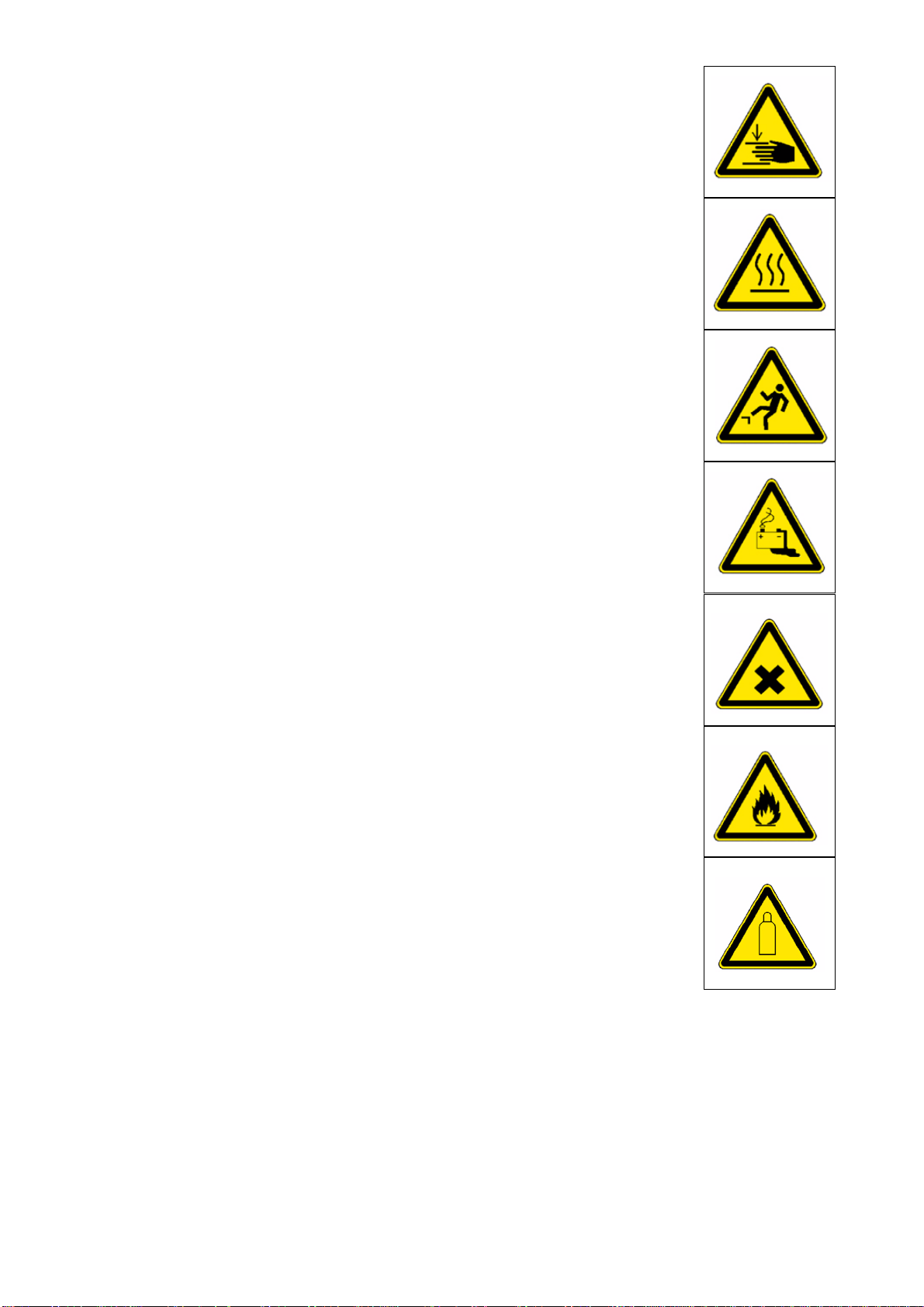
Attention: gas bottles!
V_01_GB.fm
V 3

1.3 Prohibitive signs
It is prohibited to open / step on / reach into / perform / adjust
during operation or when the traction engine is running!
Do not start the engine/drive!
Maintenance and repair works can be carried out only with the Diesel engine turned off!
Do not sprinkle with water!
Do not extinguish with water!
A
Do-it-yourself maintenance is prohibited!
Maintenance can be performed by skilled professionals only!
Contact the Dynapac service!
Danger of fire: do not use open flame and no smoking!
Do not turn on!
V 4
V_01_GB.fm

1.4 Protective gear
A
The applicable local regulations may define the use of different protective gear!
Observe these specifications!
Protect your eyes with googles!
Wear appropriate head protection!
Protect your hearing with appropriate ear mufflers!
Protect your feet with safety footwear!
Always wear tight, conforming working coveralls!
Wear visibility vest for good visibility!
In case of polluted air, wear respiratory mask!
V_01_GB.fm
V 5

1.5 Environmental protection
A
The locally applicable acts, directives and waste disposal regulations shall be observed, even if the attention is not specifically directed to these.
During cl eanin g, m ainte nance and r epair op erati o n th e mater ial s p olluting water e .g.:
- lubricants (oils, grease)
- hydraulic oil
-gas oil
- coolant
- detergents
may not enter the soil or the sewer system!
These materi als shall be colle cted, stored, tran sported in the cor rect
containers until professional disposal!
Material harmful for the environment!
1.6 Fire prevention
A
The applicable local regulations may specify the mounting of appropriate fire extinguishers!
Observe these specifications!
Fire fighting device
(optional equipment)
V 6
V_01_GB.fm

1.7 Further instructions
m
A
m
m
Observe the manufacturer's and other instructions!
e.g. the maintenance instructions of the engine manufacturer
Description / figure in case of an electrically heated design!
Description / figure in case of an electrically heated design!
V_01_GB.fm
V 7


A Correct use and application
A
The “Guidelines for the Correct Use and Application of Paver finishers” compiled by
Dynapac are included in the scope of delivery for the present machine. The guidelines are part of the present operating instructions and must always be heeded. National regulations are fully applicable.
The road construction machine described in the present operating instructions is a
paver finisher that is suited for laying mixed materials, roll-down concrete or leanmixed concrete , track-layi ng ballast and unbound m ineral aggregate s for founda tions
for paving.
This machine sh all be u sed, operat ed and ma intained for the pu rpose of the intended
work as included i n the oper ation manual. A ny other u se is regarded as improper use
and can cause injury to persons or damage to the paver finisher or other equipment
or property.
Any use going beyond the range of applications described above is regarded as improper use and is expr essly forbidden! E specially in those cases wher e the paver finisher is to be operated on inclines or where it is to be used for special purposes
(construction of dump s, dams), it is absolutely necessary to contact the m anufacturer.
Duties of th e u ser : A “ user” wi thin the m eaning of the presen t ope rati ng instru cti ons
is defined as any natural or legal person who either uses the paver finisher himself,
or on whose behalf it is used. In special cases (e.g. leasing or renting), the user is
considered the person who, in accordance with existing contractual agreements between the owner and the user of the paver finisher, is charged with the observation
of the operating duties.
The user must ensure that th e paver finisher is only used in the stipu lated mann er and
that all danger to life and limb of the operator, or third parties, is avoided. In addition
to this, it must be ensured that the relevant accident pr evention regulat ions and othe r
safety-related provisions as well as the operating, servicing and maintenance guidelines are observed. The user must also ensure that all persons operating the equipment have read and understood the present operating instructions.
Mounting of attachments: The paver finisher must only be operated in conjunction
with screeds that have been approved by the manufacturer. Mounting or installation
of any attachment s that will interfere with or supple ment the functions of the paver finisher is per mitted only after w ritten a ppro val by the ma nufact urer has bee n obtain ed.
If necessary, the approval of local authorities has to be obtained.
Any approval obtained from local authorities does not, however, make the approval
by the manufacturer unnecessary.
A_01_GB.fm 1-2
A 1


B Description of the screed
1 Application
The SVEDALA D EMAG EB 34 screed is ope rated in conjuncti on with a paver finish er .
The screed is used for laying:
- bitumen materials,
- roll-down concrete or lean-mixed concrete,
- track-laying ballast or
- unbound mineral aggregates for foundations for paving.
B_EB34_DEM_05.08_GB.fm. 1-12 -01.01.07
VB340.wmf
A
The hydraulically extendable screed is intended for laying with variable operating
widths.
For the technical specifications of the screed, refer to the section ”Technical Data”.
B 1

2 Assemblies
Tamper and vibration elements: The tamper knives converging in the middle area
prevent seams in the middle.
Auxiliary vibration (option) supports the compacting process, thus improving the texture.
The tamper and the vibration elements can be individually switched on and off and
controlled with regard to speed.
Continuous speed control always ensures optimum compacting results for the different materials and layer thicknesses.
Basic scre ed an d ext endab le pa rts: The screed parts which can be hydraulically
extended from the middle section („basic screed“) extend the working width of the
screed at the push of a button.
An expensive guide system ensures high levels of stability.
The angle and the height of the extendable parts in relation to the basic screed can
be quickly and easily readjusted.
A
These adjustments, the basic adjustments of the screed in relation to the paver finisher and adjustment of the crow ning are d escri be d in chap ter E , „Set- up a nd mo di fication“.
Extensio n pa r ts : The working width can be increased through the use of extension
parts which are very simple to install.
Side shields: The side shields serve to prevent the material from overflowing to the
outside.
- Heated side shields
- Cut-off shoes
Hinged walkway plates: During installation, the hinged walkway plates should be
folded down and snapped into place.
The walkway plates may on l y be folded up for a short tim e in speci al cases ( e.g. ma terial to be laid along a wall).
B 2
B_EB34_DEM_05.08_GB.fm. 2-12 -01.01.07

Screed heater system: Two different heater systems are available as options:
Gas heater: The propane gas flame band heater features a tried-and-tested design
and is easy to handle.
The electronic te mperatur e and f lame monito ring system ensures short hea ting times
and constant temperatures.
Air guides to the tamper knives and side plates ensure efficient use of heat.
Electric h eater: The advantages of the electr ic screed he ater are its trie d-and-te sted
design, problem-free handling and maximum possible service friendliness thanks to
maintenance-free
operation.
Short heating times, con stant temperature s and efficien t heat utilisation are the refore
assured than ks to the various, separ ately m oni tored and contr ol led he ating sections.
These are designed in the form of heating strips, sensibly arranged in the bottom
plates and tamper knives of each screed section.
If extension parts are fitted to the screed, only one single, easily installed plug connection need be fitted to the supply and control cable leading to the neighbouring
screed component.
The heating system is monitored and controlled in the switch cabinet.
A
Both types of heater and their operation are described in the following chapters of
these operating instructions.
Symbols are assigned to the different descriptions and figures:
- Description / depiction when equipped with gas heater
- Description / depiction when equipped with electric heater
B_EB34_DEM_05.08_GB.fm. 3-12 -01.01.07
B 3

3 Safety
f
3.1 Remaining risks at the screed
f
f
f
The safety devices of th e paver finisher and of the screed a re described in cha pter B,
section 3 of the operating instructions for the finisher.
Danger of squeezing!
At all moving parts of the screed, there is a danger of crushing , trapping or shearing.
Keep away from these parts!
Danger of being pulled in!
A danger of catching, winding or drawing-in exists at all rotating or
circulating parts of the screed.
Keep away from these parts!
Danger of falling!
Never jump on or off the when the machine is in motion! Only use
the access boards and steps provided!
f
f
Danger of fire and explosions!
Work on the heater system involves the danger of fire and explosion.
Do not smoke! Do not use open fires!
Danger of electric voltage
Any failure to follow the safety precautions and safety regulations
when operating the electric screed heater (o) leads to the risk of
electric shock.
Danger to life!
All maintenance and repair work on the screed's electrical system
may be carried out by a specialist electrician only.
B 4
B_EB34_DEM_05.08_GB.fm. 4-12 -01.01.07

Danger of burning!
f
Heating the screed heater l eads to danger due to hot surfaces, particularly on the bottom plates and side shields.
Keep away from these parts! Or wear protective gloves!
- Always wear all protective clothing required!
Failure to wear protective clothing or wearing protective clothing in an improper
manner can be dangerous to health.
- Ensure that all protective covers and hoods are fitted and secured accordingly!
- Immediately rectify any damage which is determined! Operation must not be con-
tinued when the machine is defective!
- Always make sure during operation that no-one is endangered by the machine!
B_EB34_DEM_05.08_GB.fm. 5-12 -01.01.07
B 5

4 Technical data
4.1 Dimensions
Basic width 1,70 1,70 m
Working width:
min. width with 2 cut-off shoes
hydraulically extendable to
Depth of the bottom plates:
basic screed
extendable parts
EB34(V) EB34(TV)
1,20
3,40
310
310
1,20
3,40
270
270
m
mm
A
As regards extension of the screed, refer to the chapter entitled „Set-up and modification“.
4.2 Weights
Basic screed with extendable parts 1,35 1,35 t
plus:
side shields
350 mm per extension part
500 mm per extension part
EB34(V) EB34(TV)
68
70
105
68
84
120
kg
B 6
B_EB34_DEM_05.08_GB.fm. 6-12 -01.01.07

4.3 Adjustment/equipment features
Crowning:
- Adjustment range -2%... +4 %
- Adjusting mechanism with ratchet via chain
Height/angle adjustment of extendable parts Separate systems
Hinged walkway plate Standard
Lubrication system Individual lubrication points
4.4 Compacting system
Tamper system Vertical impact tamper
Tamper stroke max. 3,5 mm
Tamper frequency 0 ... 1500 rpm
(infinitely adjustable) (0 ... 25 Hz)
Vibration (option) 0 ... 3300 rpm
(infinitely adjustable) 0 ... 55 Hz)
Oil motors:
- for tamper (in basic screed/extendable part) 2/2
- for vibration (in basic screed/extendable part) 2/2
B_EB34_DEM_05.08_GB.fm. 7-12 -01.01.07
B 7

4.5 Gas heater system
Fuel (liquefied gas) Propane gas
Burner type Pipe burner
Heater control system
(switch cabinet on the screed)
Gas bottles (on the screed)
- Capacity per bottle
- Gross weight per bottle
Operating pressure (downstream of pressure
reducer)
Electronic ignition,
temperature monitoring,
flame monitoring
1 units
70 l
33 kg
Approx. 1.5 bar
B 8
B_EB34_DEM_05.08_GB.fm. 8-12 -01.01.07

4.6 Electric heater EB 34 (V)
Type of heater
Number of heating strips
- Per bottom plate 2
Screed heating system total output:
- Main screed - bottom plate
- Extendable part - bottom plate
- Extension part, 350 mm - bottom plate
- Extension part, 500 mm - bottom plate
4.7 Electric heater EB 34 (TV)
Type of heater
Number of heating strips
- Per bottom plate
- Per tamper knife
Electric heater with heating
strips in bottom plates
1100
1100
450
650
Electric heater with heating
strips in bottom plates and
tamper knives
2
1
Units
Watts
Units
Screed heating system total output:
Main screed - bottom plate
Main screed - tamper knife
Extendable part - bottom plate
Extendable part - tamper knife
Extension part, 350 mm - bottom plate
Extension part, 350 mm - tamper knife
Extension part, 500 mm - bottom plate
- Extension part, 500 mm - tamper knife
1100
650
1100
650
450
250
650
350
Watts
B B_EB34_DEM_05.08_GB.fm.GB 9-12 -01.01.07
B 9

5 Location of instruction labels and type plates
2 3
5
g
n
u
t
4
h
u
c
i
3
r
t
r
r
e
h
2
f
r
a
2
u
e
F
1
n
r
w
o
i
e
n
4
t
f
i
1
r
k
e
n
n
e
h
e
i
o
o
w
c
t
i
S
N
n
t
k
i
S
k
e
O
e
e
S
h
1
S
3
c
N
n
S
O
o
i
t
1
k
r
e
e
f
S
r
e
w
n
i
e
h
c
S
N
g
O
n
-
N
u
1
O
r
N
-
e
1
O
N
h
-
c
O
1
i
-
s
t
1
p
u
a
H
N
O
N
O
1
-
N
1
O
N
1
O
N
O
1
-
N
1
O
-
1
A
L
A
D
E
V
S
C
°
4
n
O
T
o
i
U
t
6
4
k
A
F
e
F
2
O
S
2
1
F
F
F
n
3
0
o
O
F
i
F
-
0
t
O
0
0
F
k
F
-
K
2
e
0
O
F
F
S
-
O
O
C
0
F
T
-
F
1
O
0
F
S
-
F
n
0
O
F
o
-
i
F
t
0
F
O
k
-
0
O
e
-
S
0
3
F
F
n
F
o
O
i
t
F
-
F
k
0
O
F
-
e
F
0
F
O
S
-
F
0
F
O
-
F
0
F
O
-
F
0
F
O
-
F
O
F
0
0
O
-
0
4
VB340.wmf
Pos. Designation
1 Screed type plate
2 Gas system type plate *
3 Bottle valve operating instructions *
4 Warning plate „Hot surfaces“
5 Safety seymbols „Danger of electrical voltage“**
1
5
(o)
B 10
6 Electric heater operating instructions**
* With „gas heater“ equipment only
** With „electric heater“ equipment only
B B_EB34_DEM_05.08_GB.fm.GB 10-12 -01.01.07

5.1 Screed type plate (1)
1
4
Typ_Bohl3.tif
Pos. Designation
1 Screed type
5
3
2
2 Maximum operating weight of the screed
3 Screed number
4 Year of manufacture
5 Manufacturer
B B_EB34_DEM_05.08_GB.fm.GB 11-12 -01.01.07
B 11

5.2 Liquefied gas system type plate (2)
GASANL3.TIF
Pos. Designation
1 Year of manufacture
2 Type of gas to be used
1
2
3
4
5
6
3 Connection overpressure in mbar
4 Average gas consumption of the installed screed, in kg/h
5 Average gas consumption of the screed extension parts, in kg/h
Maximum permissible mass flow of the installed
6
hose rupture protection in kg/h
B 12
B B_EB34_DEM_05.08_GB.fm.GB 12-12 -01.01.07

C Transportation
1 Safety regulations for transportation
m
Accidents may occur when the paver finisher and the screed are not properly prepared for transportation or when transportation is carried out improperly!
Retract the e xtension parts of the screed to the basic width and r emove all exte nsi on
parts that may have been attached.
Remove all loose and protruding parts (limiting plates, remote controls, etc.). When
transporting under a special permit, secure these parts!
Stow all par ts which are not p ermanently installed on the screed in the boxes provided
for this purpose.
Properly reattach all guards after transportation.
C 614_DYN_DEM.GB 1-2 - 01.01.07
C 1

2 Transporting the removed screed
A
f
A
2.1 Transportation by crane
m
f
The procedure required to load and transport the screed when installed on the fin-
isher is described in the operating instructions for the finisher.
The screed must be retracted to the basic width. All protruding or loose parts and the
gas bottles for the screed heating system (o) (see Chapters E and D) must be removed. Hydraulic and electrical connections must be disconnected.
Heed the capacity of the fork-lift truck / of the crane and the lifting gear (chains, cables, hooks, etc.)!
For the weights and the dimensions of the screed, refer to Chapter B, section „Technical data“.
Attach the hooks to the attachment points (1, 2) provided for this purpose.
Make sure t hat th e scre ed is in a com pl etely h orizontal position w hen attache d to the
gear; otherwise, oil and grease can leak out.
This is harmful to the environment!
Suspended load!
Never step below the suspended load!
2.2 Transportation by fork-lift truck
m
f
Always note that the centre of gravity of the screed or accessories box may be offcentre.
When a fork-lift truck i s used for transpo rtatio n, ther e is the danger that the loa d may
tip over or that parts may fall down. Keep away from the danger area!
1 2
C 2
VB340.wmf
C 614_DYN_DEM.GB 2-2 - 01.01.07

D Operation
1 Notes regarding safety
f
Improper operation of the screed or the screed heater can endanger persons.
- Ensure that all protective devices and covers are available and appropriately secured!
- Immediately rectify any damage which is determined! Operation must not be continued when the machine is defective!
- Always ensure that no person is endangered when working!
- Do not let any person ride along on the screed!
D_E34_VB340_05.08_G B.fm 1-26- 01.01.07
D 1

2 Operation of the screed
A
For all general functions of the finisher
and the screed that are not specially related to the present screed, refer to the
operating instructions of the finisher.
2.1 Extend/r etr act screed
To extend or retract the hydraulica lly adjustable extension parts,
- actuate the switch (1) on the remote
controls installed on the right-hand
and the left-hand side of the screed
(option: on the contr ol panel of the fin isher).
- The screed h azard warning system ( at
the rear lights of the finisher) starts
flashing.
m
There is a danger of squeezing while t he
extension parts are extended or retracted.
Make sure that there is no-one in the
danger area!
1
3
2
- A pointer (2) and a scale (3), from
which the extended width can be read
off, can be found on each of the extendable parts.
Remote_F6.bmp/VB340_Skala.wmf
D 2
D_E34_VB340_05.08_G B.fm 2-26 -01.01.07

2.2 Adjusting the tamper (o)
The tamper function is switched on and
off using the switch (2) on the finisher's
operating panel (see finisher operating
instructions). (o Pavers equipped with
PLC system: Button (2a))
The tamper frequency (number of
strokes a minute) is set using the speed
regulator for the tamper (4). This can be
found on the railing on th e left- hand side
of the machine (under heating switch
cabinet).
2
3
Adjustment range:
Tamperswitch.bmp/Vibrationswitch.bmp
0 – 1500 rpm =
0 – 25 strokes a second
Adjusting the vibration
The vibration fun ction i s switched on and off usi ng the switch (3) on the fini she r's op erating panel (see finisher operating instructions).
The speed regulator for vibration (5) can be found on the railings on the right-hand
side of the machine (separator fluid system holder).
Adjustment range:
0 – 3300 rpm =
0 – 55 strokes a second
4
D_E34_VB340_05.08_G B.fm 3-26- 01.01.07
5
VibDrehz340.wmf/TampRPM340.wmf
D 3

Tamper/vibration frequency displays
(o) (6) / (7)
The display can be used to optimaly adjust the tamper and vibration speed to
different paving situations.
When the igniti on is switched on , the relevant frequency is automatically displayed (range 0 to maximum).
During paving, the frequencies can be
easily checked and, if necessary, readjusted using the rotary knobs (4),(5).
6
RPMVB340.bmp
7
D 4
D_E34_VB340_05.08_G B.fm 4-26 -01.01.07

3 Operation of the gas heater system with flame monitoring
3.1 Switch cabinet for screed heating system
9
10
11
18 17 2019
12
D_E34_VB340_05.08_G B.fm 5-26- 01.01.07
15 161314
D 5

Pos. Designation
Heating system master switch ON/OFF
9
- Position 1: Heating system ON (o) and tamper/vibration speed displays ON
- Position 0: Heating system OFF (o) and speed displays OFF
10 Controller for high/low temperature pre-selection, basic screed
11 Controller for high/low temperature pre-selection, extendable parts
12 Operating display, green
13 Left middle section operating display, yellow
14 Left extendable part operating display, yellow
15 Right middle section operating display, yellow
16 Right extendable part operating display, yellow
17 Left middle section malfunction display, red
18 Left extendable part malfunction display, red
19 Right middle section malfunction display, red
20 Right extendable part malfunction display, red
D 6
D_E34_VB340_05.08_G B.fm 6-26 -01.01.07

3.2 Gas supply diagram
6
5 5
32
4
6
1
Gaslauf_EB51.bmp
Pos. Designation
1 Gas bottles
2 Bottle valves
3 Pressure reducer with pressure gauge
4 Hose rupture protection devices
5 Flame band burner
6 Solenoid valves
D_E34_VB340_05.08_G B.fm 7-26- 01.01.07
D 7

3.3 General notes on the gas heater system
The heater of the screed burns propane
gas (liquefied gas). The gas bottle
stands on the finisher.
The heater is equipped with an electron ic flame and a temperature monitoring
system.
GHeiz_340.cdr
Heed the following points before commissioning the heater system:
29
- The gas bottles must always be in the
position provided for this purpose on
the screed, and must be secured using the supplied strap retainers.
The bottles must be fixed in position
so that they cannot turn around their
longitudinal axis even while the paver
finisher is in operation.
- The liquefied gas system must not be
operated without the hose rupture protection device (29). It is also absolutely necessary that the pressure
reducing valve is installed before the
system is put into operation.
Gasflas.tif
- The gas pressure must not fall below
1.0 bar. Danger of explosion in the burner!
- All gas hoses must be checked for external damage before use, and must be immediately replaced with new hoses if any defects are found.
f
D 8
There is a danger of fire and explosions when handling gas bottles and working on
the gas heater.
Do not smoke! No naked flames!
D_E34_VB340_05.08_G B.fm 8-26 -01.01.07

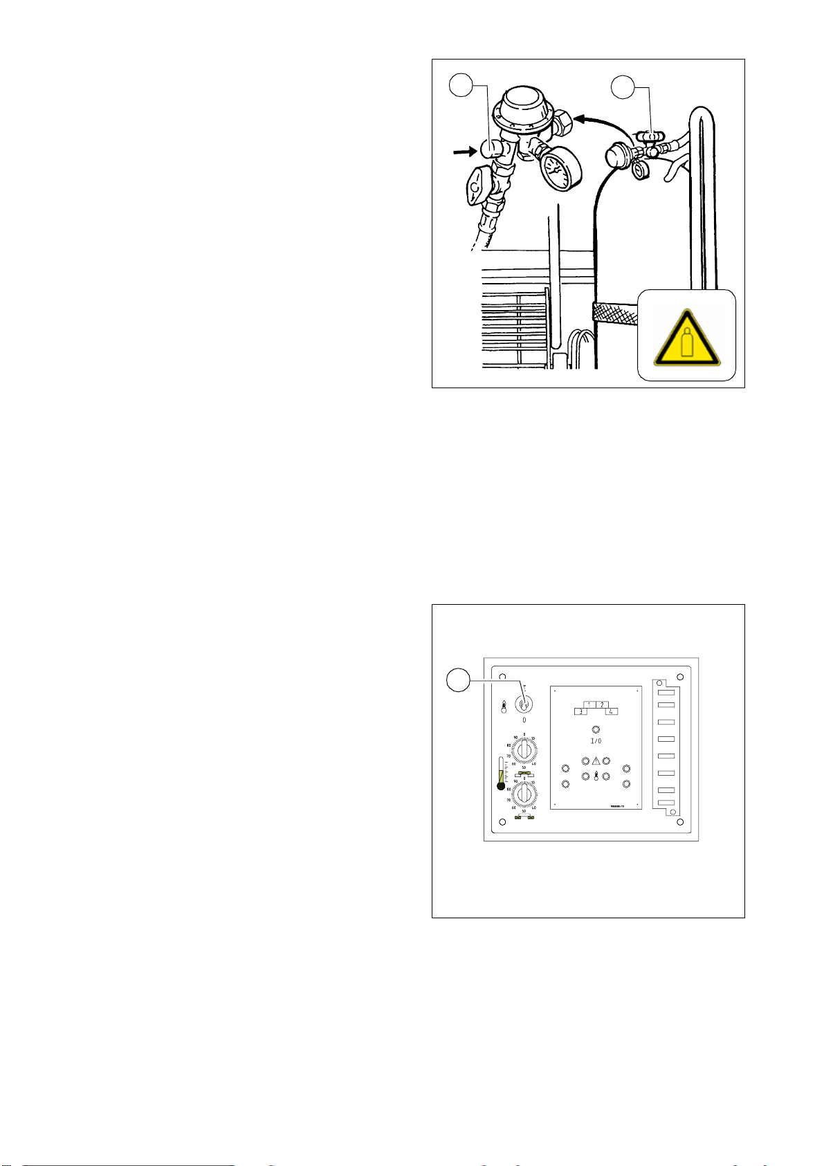
3.4 Connection and leak test
The gas pipe system of the basic screed
and the extend able pa rts is permanently
installed. To connect the gas bottles:
- Unscrew the protective caps from the
bottle valves and screw onto the rear
of the bottle bracket.
- Check whether the q uick action valves
are closed.
- Check that the bottle valves (30) are
properly closed.
Install the gas h oses with the pressure
reducers and the hose rupture protection devices (29) on the bottles.
A
Note:
The gas connections always have left-handed threads!
29
Gasflas.tif
30
m
Make sure the gas pipe system has no leaks.
D_E34_VB340_05.08_G B.fm 9-26- 01.01.07
D 9
3.5 Commissioning and checking the
heating system
The gas heating system is operated with
two gas bottles.
- Check whether the battery master
switch is switched on.
- Open the bottle valves (30).
Unlock the safety valve by pressing
the hose rupture protection device
(29).
- Open the quick action valves.
A
The following sequence must be adhered to in order to guara ntee a malfunction-free ignition and heating phase:
- 1. Place screed on the ground
- 2. Fully retract the finisher's levelling cylinders
- 3. Ignite the screed and allow to heat slightly in this position
- 4. As soon as sufficient heat is available, the screed can be raised
29
Gasflas.tif
30
Ignition process
- Switch on the On/O ff switch (27) in the
switch cabinet (upwards).
- This opens the electromagnetic
non-return valves for the gas supply
to the burners;
- It activates the electronic ignition
system, causing the gas to be automatically ignited by the spark plugs
and controlled by the flame monitoring system.
27
GHeiz_340.cdr
D 10
D_E34_VB340_05.08_G B.fm 10-26 -01.01.07

3.6 Function of the flame monitoring system
32
17
16
11
18
19
35 34
33
13
12
15
14
Pos. Designation
11 Operating display, green
12 Left middle section operating display, yellow
13 Left extendable part operating display, yellow
14 Right middle section operating display, yellow
15 Right extendable part operating display, yellow
16 Left middle section malfunction display, red
17 Left extendable part malfunction display, red
18 Right middle section malfunction display, red
19 Right extendable part malfunction display, red
D_E34_VB340_05.08_G B.fm 11-26- 01.01.07
32 Switch cabinet on the screed
33 Ignition boxes on the individual screeds
34 Red indicator lamp on the ignition box in the corresponding screed
35 Yellow indicator lamp on the ignition box in the corresponding screed
D 11

Via the temperature sensor and flame monitoring system, the electronics monitor gas
heater operation. If there is no stable flame at the ignition burner within 7 seconds,
the electronics indi cate a malfun ction. Th e gas supply is interrup ted and the red indi cator lamps on the ignition box and in the switch cabinet light up.
A
m
3.7 Setting the temperature level
In the event of a malfun cti on duri ng the switch-on phase, the starting process can be
repeated up to three times. If the malfunction still occurs after three start-ups, the
cause of the malfunction has to be eliminated before starting again.
When the flame is correct, the screed is heated until the temperature sensors in the
individual screed s interrupt the heating process. Du ring the heating phase, the yellow
indicator lamps (12, 13, 14, 15) in the switch cabinet and the yellow indicator lamps
on the ignition boxes (35) indicate a correct flame at the burners.
In the event of a malfunction, the red indicator lamps (16, 17, 18, 19) in the switch
cabinet and the red indicator lamps on the ignition boxes (34) indicate that the flame
at the burners is not correct.
The indicator lamps are important for trouble-free operation of the ignition system.
Therefore, defective bulbs should be immediately replaced!
Temperature level controller for the basic screed (9)
>: Higher temperature
<: Lower temperature
A
Temperature level controller for extendable parts (10)
>: Higher temperature
<: Lower temperature
Use the high temperature to preheat the
screed and the extendable parts/extension parts before starting work; this prevents bitumen materials from sticking to
the tamper knives and to the bottom
plates on the first meters laid.
Usually, the switches can be toggled to the low temperature after a short time.
9
10
GHeiz_340.cdr
D 12
D_E34_VB340_05.08_G B.fm 12-26 -01.01.07

3.8 Switching off the heater
After work has been comp leted, or when
the heater is no longer required:
- Switch off the On/Off switch (8) in the
switch cabinet.
- Close the quick action valves and both
bottle valves (30).
m
If these valves are not closed, there is a
danger of fire and explosion due to the
possible escape of uncombusted gas!
Always close the valves during breaks
and after work has been completed!
3.9 Exchanging the gas bottles
- Check whether the q uick action valves
and both bottle valves (30 ) are closed.
- Unscrew the gas hoses.
- Screw the protective caps for the bottle valves onto the gas bottles.
- Screw pressure reducer onto the
available mounting bracket.
8
GHeiz_340.cdr
30
f
Gas bottles that are full or not compl etely
emptied are under pressure.
Therefore, make sure that bottles with
their protective valve caps removed are
protected from severe impact (particularly in the area of the valves or on the
valves themselves)!
Gasflas.tif
- Connect new gas bottles (see section 3.4, „Connection and leak test“).
D_E34_VB340_05.08_G B.fm 13-26- 01.01.07
D 13

4 Operating the electric heater
4.1 Switch cabinet for screed heating system
15
16
17
18
22
23
24
6
8
4
5
1
3
2
7
9
11
13
21
19
A
D 14
10
20
12
Schalttafel_340E.wmf
18
The arrangement of the individual elements may vary slightly!
4 x 230 V
2827 29 30
D_E34_VB340_05.08_G B.fm 14-26 -01.01.07

Item Designation
1 EMERGENCY STOP button
2
Check button for insulation monitoring and insulation error pilot lamp
3 Insulation monitoring reset button
4 Generator telltale lamp
5 Heating ON/OFF
6 Circuit breaker for heating section 1
7 Circuit breaker for heating section 2
8 Circuit breaker for heating section 3
9 Circuit breaker for heating section 4
10 Heating section 1 telltale lamp
11 Heating section 2 telltale lamp
12 Heating section 2 telltale lamp
13 Heating section 4 telltale lamp
14 Headlights On / Off (sockets 25+26)
15 Headlights On / Off (sockets 27+28)
16
17
Circuit breaker for sockets 25+26
Circuit breaker for sockets 27+28
18 Socket (heating) for main screed on left
19 Socket (heating) for main screed on right
20
Socket (heating) for extendable part on left
21 Socket (heating) for extendable part on right
22 Circuit breaker for generator telltale lamp
23 Main fuse and EMERGENCY STOP trigger
24 Control and monitoring unit STC2000
25 230 volt socket for additional headlight
26 230 volt socket for additional headlight
27 230 volt socket for additional headlight
D_E34_VB340_05.08_G B.fm 15-26- 01.01.07
28 230 volt socket for additional headlight
D 15

4.2 General information on the heating system
The electric heating system is supplied
with power by a generator on board the
paver which is controlled fully-automatically controlled in accordance with requirements.
Heating resistors in the form of heating
strips ensure direct temperature transition and even distribution of heat.
Each screed section is heated by three
heating strips. Two can be found on the
bottom plate and one on the tamper
knife.
Temperature display and temperature
control are carried out independently of
one another and in an infinitely variable
manner for: The left basic screed, right
basic screed, left extendable part and
right extendable part by means of control unit STC2000 o n the hea ting syste m
switch cabinet.
The heating system is connected to other fitted screed components via simple
plug connections.
As an option, the switch cabine t can also
be fitted with additional 230 volt sockets
for external consumers (e.g. additional
lighting).
Since fuels (gas, diesel) are not handled
and insulation monitoring takes place,
maximum possible prote cti on of person nel is offered.
Schalttafel_340E.wmf/VB340.wmf
f
f
Beware of hot surfaces! Danger of burning!
Maintenance and repair work on electrical systems with medium voltage levels, e.g.
the screed heating system, may only be carried out by specialist electricians or persons instructe d in electr ical en gineeri ng work if the ap propri ate test devices ar e used.
Always comply with rel evant tech nical elec trical prote ction precau tions. Danger to life
as a result of accidents involving medium voltage levels!
D_E34_VB340_05.08_G B.fm 16-26 -01.01.07
D 16

4.3 Isolation monitor
The function of the protective insulation
monitoring measure must be checked
every day before starting work.
A
f
This check only checks the function of
the insulation m onitor, not whether an insulation fault has occurred on the heating sections or consumers.
- Start the paver's engine.
- Switch heating system switch (1)
to ON.
- Press test button (2).
- The indicator lamp integrated into the
test button signals „insulation fault“
- Press reset button (3) for at least 3
sec. to delete the simulated fault.
- The indicator lamp goes out.
If the test is conducted successfully,
work may be undertaken with the scre ed
and external consumers may be used.
If the „insulation fault“ indicator lamp displays a fault even before the test button is
pressed or if no fault is displayed during the simula tion, work must not be underta ken
with the screed or with connected, external equipment.
Schalttafel_EB5075_neu.wmf
3
2
1
f
f
f
The screed and equ ipm en t must be ch ecke d or rep air ed by a specia list elec tr ician. Only t hen may wor k aga i n be und er tak en wit h th e scr eed and equ ipm en t.
Danger due to electrical voltage
Non-adh er ence to t he safe ty pr ecau tio ns and s afet y r egu lat ion s
when operating the electric screed heating system leads to a
risk of electric shock.
Danger to life!
All maintenance and repair work on the screed's electrical system may be carried out by a specialist electrician only.
D_E34_VB340_05.08_G B.fm 17-26- 01.01.07
D 17

Insulati on fau lts
A
f
A
A
If an insula ti on f ault o ccurs dur ing o pera ti on, and the indi cator l am p d isplays a n insu lation fault, the operator may proceed as follows:
- Switch the switches of all external equipment and the heating system to OFF and
press the reset button for at least 3 seconds to delete the fault.
- If the indicator lamp does not go out, the fault lies in the generator.
No further work may be carried out.
- If the indicator lamp goes out, the switches of the heating system and external
equipment can be switched back to ON one after another until a message again
appears and the system is shut-down.
- The equipment found to be faulty must be removed or must not be engaged, and
the reset button must be pressed for at least 3 seconds to delete the fault.
Operation may now be continued - without the faulty equipment, of course.
The generator or electrical consumer found to be faulty must be
checked or repaired by a specialist electrician. Only then may
work again be carried out with the screed and equipment.
D 18
D_E34_VB340_05.08_G B.fm 18-26 -01.01.07

4.4 Commissioning and checking the
heating system
A
In order to reach the required temperature, the heating system should be
switched on approx. 15 - 20 minutes be fore the start of paving.
- Switch on the paver's engine.
- Switch on heating system ON / OFF
switch (1).
The heating system is activated and the
heating process begins.
During the hea ting process, t he individu al screed parts' heating systems' indicator lamps (2) light up.
Once the set temperature has been
reached, the indicator lamps go out one
after another.
Once all screed parts have reached the
desired temperature, paving operation
may begin.
1
3
A
If additional heating occurs during paving operation, this is indicated by the in-
Schalttafel_340E.wmf
2
dicator lamps (2).
The heating system indicator lamp s in th e contr ol an d mon i toring unit ( 3) can also be
observed.
D_E34_VB340_05.08_G B.fm 19-26- 01.01.07
D 19

4.5 Temperature display, setting temperature level
The temp erature display and t emperatu re lev el settin g fo r the indivi dual sc reed
elements ar e car rie d out vi a t he con tr ol and monitoring unit in the screed heating system's switch cabinet.
4.6 Operating the control and monitoring unit
2 3
1
4
STC20002.bmp
6
5
6a
6b
5a
5b
8
7
7a
7b
8a
8b
D 20
D_E34_VB340_05.08_G B.fm 20-26 -01.01.07

Pos. Designation / function
1 Display. Nominal and actual temperature display. Fault code display.
Auto / OFF button
2
- Starts and stops the system. When in the „OFF“ switch position, „OFF“
is shown in the display.
Increase in nominal temperature on the selected screed section.
3
- If pressed briefly, the current tem pera ture setting for the selected screed
section is displayed.
Reduction in nominal temperature on the selected screed section.
4
- If pressed briefly, the current tem pera ture setting for the selected screed
section is displayed.
5 Selection of basic screed, left
Indicator lamp (green/red)
- Not illuminated: Screed temperature < operating temperature
- Illuminated permanently, green: Screed temperature OK (+/- 3° C of
nominal temperature)
5a
- Flashing, green: Screed temperature too high (> +3°C of nominal temperature)
- Illuminated permanently, red: Malfunction! Screed section heating system switched off, fault code shown on display.
- Flashing, red: A temperature sensor is defective. The heating system
continues to operate.
Indicator lamp (yellow)
5b
- ON: Screed section heating system in operation
- OFF: Screed section heating system off
6 Selection of extendable part, left
6a
6b
Indicator lamp (green/red)
- Refer to (5a)
Indicator lamp (yellow)
- Refer to (5b)
7 Selection of basic screed, left
7a
7b
Indicator lamp (green/red)
- Refer to (5a)
Indicator lamp (yellow)
- Refer to (5b)
8 Selection of extendable part, right
8a
8b
Indicator lamp (green/red)
- Refer to (5a)
Indicator lamp (yellow)
- Refer to (5b)
D_E34_VB340_05.08_G B.fm 21-26- 01.01.07
D 21

4.7 Temperature setting
- Select screed se cti on by p ressing bu tton.
- Depending on the desired temperature change, press button (3) or (4).
- The current nominal temperature is
shown first. Adjustment in the corresponding direction is undertaken after
1.5 seconds.
2
3
4
A
When changing the te mper atur e setting,
4 dots light up on the display.
4.8 Fault messages
When a fault occurs, the small red lamp
(5a, 6a, 7a, 8a) for the relevant screed
section lights up and the corresponding
heating system is switched off.
The fault code and faulty screed section
are shown on the display.
If several faults occur, t he last fault to occur is shown on the display; the faults
which occurred previously can be called
up on the display by pressing the relevant buttons.
To delete the fault display, the fault first
has to be rectified and then the relevant
section button pressed until the small
red lamp goes out.
STC20002.bmp
5a
6a
STC20002.bmp
7a
8a
A
D 22
Fault codes
Fault code Meaning
50 - Defective temperature sensor
Heating system remains in operation as long as at least one temperat ure sensor functions.
If the temper ature sensor of e.g. a middl e section fails, the hea ting system is switched
to the other middle section's sensor.
A similar function is provided for the extendable parts.
D_E34_VB340_05.08_G B.fm 22-26 -01.01.07

4.9 Switching off the heating system
At the end of work or when the
heating system is not required:
- Switch off ON/OFF switch (1) of heating system.
2
1
Schalttafel_340E.wmf
D_E34_VB340_05.08_G B.fm 23-26- 01.01.07
D 23

5 Malfunctions
5.1 Problems during paving
Problem Cause
- change in the material temperature, demixing
- wrong material composition
- incorrect operation of the roller
- incorrectly prepared foundation
- long standstill times between loads
- grade control reference line is not suitable
- grade control jumps to the reference line
Wavy surface
(“short waves”)
- grade control toggles between up and down
(inertia setting is too high)
- bottom plates of the screed are loose
- bottom plates of the screed are warped or not uniformly
worn
- Screed is not operated in the float position
- too much play in the mechanical screed link/suspension
- paver finisher speed is too high
- augers are overloaded
- changing material pressure against the screed
Wavy surface
(“long waves”)
Cracks in the layer (over the entire width)
- change in the material temperature
- demixing
- roller has stopped on the hot material
- roller has turned or roller speed has been changed too fast
- incorrect operation of the roller
- incorrectly prepared foundation
- truck brake is applied too tight
- long standstill times between loads
- grade control reference line is not suitable
- incorrect installation of the grade control
- limit switch is not correctly set
- screed is empty
- screed has not been switched to the floating position
- too much play in the mechanical screed link
- auger is set too deep
- auger is overloaded
- changing material pressure against the screed
- material temperature is too low
- change in the material temperature
- moisture on the foundation
- demixing
- wrong material composition
- wrong layer height for maximum grain size
- cold screed
- bottom plates of the screed are worn or warped
- paver finisher speed is too high
D 24
D_E34_VB340_05.08_G B.fm 24-26 -01.01.07

Problem Cause
- material temperature
Cracks in the layer (centre strip)
- cold screed
- bottom plates are worn or warped
- wrong crowning
- material temperature
- screed extension parts are incorrectly installed
Cracks in the layer (outer strip)
- limit switch is not correctly set
- cold screed
- bottom plates are worn or warped
- paver finisher speed is too high
- material temperature
- change in the material temperature
- moisture on the foundation
- demixing
- wrong material composition
- incorrectly prepared foundation
- wrong layer height for maximum grain size
Layer composition inconsi stent
- long standstill times between loads
- vibration is too slow
- screed extension parts are incorrectly installed
- cold screed
- bottom plates are worn or warped
- Screed is not operated in the float position
- paver finisher speed is too high
- auger is overloaded
- changing material pressure against the screed
Marks in the surface
screed does not
react as expected to corrective
measures
- truck hits too much against the finisher while aligning to the
finisher
- too much play in the mechanical screed link/suspension
- truck brake is applied
- vibration is too high while standing on a spot
- material temperature
- change in the material temperature
- wrong layer height for maximum grain size
- incorrect installation of the grade control
- vibration is too slow
- Screed is not operated in the float position
- too much play in the mechanical screed link
- paver finisher speed is too high
D_E34_VB340_05.08_G B.fm 25-26- 01.01.07
D 25

5.2 Malfunctions on the screed
Malfunction Cause Remedy
Tamper or vibration is not functioning
Screed cannot be
lifted
Tamper is obstructed by cold
bitumen
Hydraulic oil level in the tank
is too low
Pressure limiting valve is defective
Properly heat the screed
Top up the oil
Replace the valve; if necessary, repair and adjust the
valve
Seal or replace the connec-
Leak in the suctio n li ne o f the
pump
tions
Tighten or replace the hose
clamps
Oil filter is soiled
Clean the filter; if necessary,
replace the filter
Oil pressure too low Increase the oil pressure
Leaking seal Replace the collar
Screed relieving or charging
is switched on
Switch must be in the centre
position
Power supply interrupted
Check fuses and cables; re-
place if necessary
D 26
D_E34_VB340_05.08_G B.fm 26-26 -01.01.07

E Set-up and modification
1 Notes regarding safety
f
f
f
Inadvertent starting of the paver finisher can endanger persons working on the
screed.
Only carry out such work with the finisher motor at a standstill unless the instruc-
tions state the opposite!
Make sure that the paver finisher is secured against being put into operation.
When lifted, the screed can still slide downwards if the mechanical screed transport
safeguard is not inserted on the finisher.
Only carry out work when the screed is secured by mechanical means!
When connecting or di sconnecting hyd raulic h oses and whe n workin g on the h ydraulic system, hot hydraulic fluid can spurt out at a high pressure.
Switch off the engine and de-pressurise the hydraulic system! Protect your eyes!
Always install exte nsi on p arts and co nversio n par ts in the p rope r m anner ! If in dou bt,
contact the manufacturer!
Mount all protective devices before re-commissioning the paver finisher.
The walking platform must always reach over the entire width of the screed.
The hinged walkway plate (option) may only be folded up under the following conditions:
- If the machine has to be backed up very closely to a wall or another obstacle,
- During transportation on a low-bed trailer.
E_EB34_VB340__05.08_G B.fm-14 02-05.08
E 1

2 General assembly
2.1 Fitting screed to finisher
- Lower screed onto a suitable base
(square pieces of wood etc.) and driv e
the finisher in reve rse to j ust in fr ont of
the screed.
Lower crossbeams and position so
that welded-on pivot of fulcrum point
on crossbeam (1) can be guided into
the relevant hole in the screed body.
Use screw and washer to secure fulcrum point inside screed body.
To assemble further, the following steps
must be undertaken on both crossbeams:
- Fit guide bolt (2) and spacer sleeve
(2a) between crossbeam and longitudinal slot of screed guidance and use
washer (2b) and self-locking nut (2c)
to secure that this produces perfect
guidance and a good degree of freedom to move.
- Use eye of turn buckle (3a) to fit retaining bolt (3) onto crossbeam to set
screed positioning angle and fit nut
(3b) provided for this purpose.
- Fit screw (4) with indicator of screed
positioning angle (4a), with washer
(4b) and self-locking nut (4c) onto
crossbeam to provide a good level of
movement.
3
Holm_Bohle340.wmf
4
2
1
4b 4c
4a
2a 2b
Holm_Bohle340_2.wmf
3
4
2
2c
3b
3a
E 2
E_EB34_VB340__05.08_G B.fm-14 02-05.08

2.2 Mounting the side shields
The side shields are mounted after all
other mounting and adjustment work on
the screed has been completed.
- Insert swing lever shaft on side shield
through hole in extendable part or extension part.
- Use clip (1) to secure internal section
of swing lever shaft to prevent shaft
from sliding back out.
Also on outer face of side shield:
- Attach control arm of parallel guide to
pivot (2) and use folding pin (3) to secure.
- Insert height adjustment crank in clip
(4) and use cotter pin (5) to secure.
1
Schildmon_340a.wmf
2
4
Schildmon_340b.wmf
3
5
E_EB34_VB340__05.08_G B.fm-14 02-05.08
E 3

2.3 Hydraulic connections
The hydraulic connections are on the rear of the finisher.
f
m
A
When installing the hydraulic connections, hot hydraulic oil can spurt out under high
pressure.
Switch off the engine and de-pressurise the hydraulic system! Protect your eyes!
When installing the hydraulic connections, make sure the environment is absolutely
clean.
Dirt in the hydraulic oil can cause the machine to fail!
The connections present depend on the screed equipment.
Position and designation of the connections:
4 3
Rück2_F6.wmf
8 7
5126
Item Designation
1 Tamper pu mp (O)
2 Tamper return –> tank (O)
3 Vibration pump
4 Vibration return –> tank
5 Extend screed, left
6 Retract screed, left
E 4
7 Extend screed, right
8 Retract screed, right
E_EB34_VB340__05.08_G B.fm-14 02-05.08

2.4 Electrical connections
A
On the rear of the finisher:
1
- Plug connector (1) for the electrical
consumers on the screed (electromagnetic valves, remote controls,
etc.).
Under the rear console (left and right):
Rück3_F6.wmf
- Sockets (2) for remote control connection cable.
The screed settings on the finisher can only be made after the electrical conne ctions
have been established.
E_EB34_VB340__05.08_G B.fm-14 02-05.08
E 5

3 Extending the screed
A
An extension part (width of 350 mm) can be fitted on either side! This produces a
maximum operating width of 4.1m.
Before the extension parts can be fitted, the following steps must be undertaken:
3.1 Removing side shields
- Remove clip (1) for securing swing lever axis from inside of screed body.
1
Schildmon_340awmf
Also on outside of side shield:
- Remove folding pin (2) from pivot (3).
- Pull splint (4) out of clip (5).
- Take off hand-operated crank.
- Pull side shield with swing lever axis
off extendable part.
3
5
2
4
Schildmon_340b.wmf
E 6
E_EB34_VB340__05.08_G B.fm-14 02-05.08

3.2 Prepari ng extension parts
If the screed is equi pped with a ta mper, to dr ive the tamper , the tamper shaft must be
fitted before fitting the extension part. The following steps are needed for this:
3.3 Removing tamper deflector plate
- Unfasten two nuts (1) from track rod
by unscrewing them several turns.
- Remove both retaining bolts (2) from
tamper deflector plate.
- Take off tamper deflector plate (3).
2 3
3.4 Assembly of tamper drive shaft
- Insert shaft (4) in relevant recess (5) of
screed body.
- Slide both parts of driver coupling (6)
onto one another with the inserted
plastic star.
3.5 Fitting tamper deflector plate
- Insert the ra il located inside th e deflector plates (3) into the grooves (7) of the
tightening rods
- Fit both retaining bolts (2) of tamper
deflector plates.
- Tighten both nuts (1) of track rods until stop is reached. To do this, the deflector
plate is tightened before the tamper.
Leitblech_340.wmf
4
Stampferwelle_340.wmf
1
6
5
7
E_EB34_VB340__05.08_G B.fm-14 02-05.08
A
The extension part is now prepared and ready to be fitted on the extendable part.
E 7

3.6 Fitting extension parts
m
The screw-on surface must be clean and, if the screed is already being used, must
be free of any bitumen residue.
This applies in particular to the base plate joints.
- Guide extension part and extendable
part together on a level support face.
The tamper drive shaft must be secured (unable to rotate) during this
process.
- Slide the drive shaft coupling half
through the releva nt hole in the screed
body of th e extendable p art with t he inserted plastic star and place on the
1
second coupling half located there.
- Abut the extension part and extendable part against one another.
- Gently tighten retaining bolts (1).
- Set height of extension part:
- Loosen lock nut (2).
- Use adjustment screw (3) to set the
3
correct height for the extendable
part.
- Tighten lock nut (2)
- Securely tighten retaining bolts (1)
2
3.7 Fitting side shield to extension part
A
Refer to Section 2.2
Gas340.wmf/Anbau_340.jpg
E 8
E_EB34_VB340__05.08_G B.fm-14 02-05.08

3.8 Screed heating system gas connections
After the extension parts have been
mounted, the connection hoses for the
extension parts' burners must be connected to the screed's pipe system.
- All hoses must be checked for exter-
nal damage prior to use and, if a ny defects are found, must be immediately
replaced with new hoses.
- The hose connection s are established
using screw connections. (1).
f
Danger of fire and explosions!
Work on the heating system involves t he
Gas_340.wmf
danger of fire and explosion.
Do not smoke! No naked flames!
- After the exten sion p arts have been rem oved , the hose s rem ain with the exte nsi on
part to which they are screwed.
3.9 Screed heater system electrical connections
Once extension parts have been fitted,
the screed heater system's corresponding electrical connections must be connected to one another.
1
5
3
f
Each screed section contains a distributor box (1), at which the plug connections for the heating strips in the bottom
plates (2) an d (3) and the heating str ip in
the tamper knife (4) have already been
established.
4
Before being used, all cables must be
2
1
checked for externally visible damage
and, if defects are found, must be replaced immediately with new cables.
614_Elektro1.eps
The connection (5) for the supply and
control cable to the neighbouring screed section
can be found on the upper side of the distribution box.
- Open the retaining tab and protective cover, plug in cable between extension part
and neighbouring screed part and secure using the retaining tab.
E_EB34_VB340__05.08_G B.fm-14 02-05.08
E 9

4Settings
4.1 Setting extendable parts
Should you need to readjust the extendable parts, this setting can be undertaken while the screed is fitted on the
finisher.
1
A
m
A
Basic setting:
- Unfasten retaining bolts (1) and lock
nuts (3).
- Adjust adjustment screws (2) and
(3a):
Raise extendable part: turn adjustment
screws (2) to the right and turn lock nut
(3) and/or adjustment screw (3a) to the
left.
All adjustment screws must be set to the
same height! This is the only way of ensuring that no scra ping occur s duri ng installation.
The extendable parts must be set to
3mm higher than the main screed!
- After the setting process:
retighten retaining bolts (1) and lock
nuts (3).
2
1
4
4b
4a
E 10
Fine adjustment, setting during installing work:
- Unfasten fasten ing bolts (1), scre w (4 )
and nut (4a).
- Perform fi ne adjustmen t by turning t he
setting nut (4b).
- Tighten down retaining screws (1) as
well as screw (4) and nut (4a) to secure the adjusting nut.
3a
3
Einstell1_340.wmf/Einstell4_340.wmf
E_EB34_VB340__05.08_G B.fm-14 02-05.08

4.2 Setting tamper height
The tampers have a fixed / non-variable
stroke of 3.5mm.
The tampers must be set to between –
0.2 mm and 0.0 mm (dimension A) in
their lower dead centre position.
The setting process always involves the
use of two thre aded pi ns (1) to which t he
drive shaft bearing blocks are secured:
1
2
A
To undertake setting, the tamper knife
must be in its lowest position:
- Loosen lock nuts (2).
- Use threaded pins (1) to set height.
- Check position of tamper knives in re-
lation to base p lates. If nece ssary, use
threaded pins (1) to correct position.
- Retighten lock nuts (2).
4.3 Setting tamper deflector plate:
Each tamper deflector plate is tightened
by means of two track rods (1) on the
tamper knife.
There should be a clearance (a) of 0.7
mm over entire width between tamper
deflector plate (4) and tamper knife (5)
-
+
Stampferwelle_340.wmf
A
B0073_A1.PIC
1
E_EB34_VB340__05.08_G B.fm-14 02-05.08
A
This dimension is set in the factory.
- The setting is undertaken using the
front nuts (2). D epend ing o n the direction of adjustment, the lock nuts (3)
have to be loosened and then retightened before adjustment.
Leitblech2_340.jpg
3
2
5
4
a
E 11

4.4 Setting side shields
The height of the side shield s is varia ble
and their sup port angle can be adjusted.
2a
To adjust height:
- Turn hand-oper ated cr ank ( 1) un til t he
height required is reached.
Setting support angle:
- Turn hand-oper ated cr ank ( 2) un til t he
angle required is reached.
A
The crank handl e can be move d into t he
recess (2b) for safekeeping.
4.5 Setting crowing
The screed is fitted with a spindle which
can be moved to positively or negatively
adjust the crowning required.
A
For adjustment range of crowning, refer
to Chapter B, Section “Technical data”.
1
2
seitenschild_340.wmf
1
3
A
- Use installed ratchet (1) to set crown-
ing.
The adjustment distance is displayed
on the scale (2) as a percentage.
To adjust in the other direction, the pin
(3) on the ratchet has to be moved.
2
DACHPR_340.wmf
E 12
E_EB34_VB340__05.08_G B.fm-14 02-05.08

4.6 Setting positioning angle
The screed positioning angle can be increased or decreased as required.
- Set the positioning angle using the
ratchet (2) installed on the upper control arm (1).
The adjustment distance is displayed
on the scale (3).
A
To adjust in the other direction, the pin
(4) on the ratchet has to be moved.
A
Ensure that both sides of the screed are
set equally!
4.7 Positioning angle correction
Adjustment section / central section
Should the positioning angle of the adjustment section have to be compared
with that of the central section, a correction can be undertaken.
1
Anstell_340.wmf
3
4
2
1a
Increase angle:
1
2a
- Unfasten lock nuts (1) and (2)
- Screw in threaded pin (2a) until the an-
2
gle required is set.
- Retighten lock nuts.
Decrease angle:
Einstell3_340.wmf
- Unscrew threaded pin (2a).
- Use stud bolt (1a) and lock nuts (1) to dr aw adjustment section back un til the angle
required is set.
- Retighten lock nuts.
E_EB34_VB340__05.08_G B.fm-14 02-05.08
E 13


F Maintenance
1 Notes regarding safety
f
f
f
Inadvertent starting of the paver finisher can endanger persons working on the
screed.
Only carry out such work with the finisher motor at a standstill unless the instruc-
tions state the opposite!
Ensure that the finisher is secured to prevent unintentional starting.
When lifted, the screed can still slide downwards if the mechanical screed transport
safeguard is not inserted on the finisher.
Only carry out work when the screed is secured by mechanical means!
- Replace spare parts, or have them replaced, properly.
! ATTENTION!
Components bea ring this sym bol may only be ope ned, check and re placed by specialist electricians!
Monitoring and repair work on electrical systems with medium levels
of voltage, e.g. the screed heating system, may only be carried out
by speciali st electricians or persons in structed in electrical engi neering work wh en using the appropriate test equipment.
Always comply with rel evant tech nical elec trical prote ction precau tions. Danger to life
as a result of accidents involving medium voltage levels!
m
Parts and spare parts that have not been approved by the manufacturer, unsuitable
tools and incorr ect instal latio n can cau se mal fu nctions, d amag e to pr oper ty or failur e
of safety devices and can endanger persons.
Use only approved parts and install them according to the specifications! If in doubt,
contact the manufacturer!
- Properly re-install all protective devices before re-commissioning the paver finish-
er.
F_EB34_VB340_05. 08_GB.fm 1-18
F 1

2 Maintenance intervals - screed in general
Interval
Maintenance point Note
50
100
250
500
10 / daily
1000 / annually
If necessary
2000 / every 2 years
q
- Clean / oil guide tubes After work is
finished
q
q
- Empty tamper compartment After work is
- Clean side shield After work is
q - Lubricate crowning adjuster
qq- Adjust guide tube play
q - Check tamper deflector plate play
q - Adjust tamper deflector plate play
q - Hydraulic hoses - vi sua l inspection
qq- Replace hydraulic hoses
q
- Have screed checked by an
expert
Maintenance q
Maintenance duri ng running- in period g
finished
finished
F 2
F_EB34_VB340_05. 08_GB.fm 2-18

3 Maintenance intervals - gas system
Interval
10
50
100
250
500
Maintenance point Note
1000 / annually
If necessary
2000 / every 2 years
q - Check the spark plugs
qq- Replace the spark plugs
q
- Have gas system checked by
an expert
Maintenance q
Maintenance during running-in per iod g
F_EB34_VB340_05. 08_GB.fm 3-18
F 3

4 Maintenance intervals - electric heating system
Interval
Maintenance point Note
10
50
100
250
500
A
1000 / annually
q - Check insulation monitoring
A
Maintenance q
Maintenance during running-in period g
All times given are the maximum permissible maintenance intervals. For aggrava t -
ed conditions of use, shorter intervals must be applied!
For the maintenance intervals and maintenance work required for the finisher, refer
to the operating instructions for the finisher.
Note national regulations on checking and inspection
intervals!
If necessary
2000 / every 2 years
Before
starting work
- Electrical system check by a
specialist electrician
F 4
F_EB34_VB340_05. 08_GB.fm 4-18

5 Lubrication points
5.1 Guide tubes
1 1
VB340.wmf
1
A
To keep the wear and thus the play of the guides as low as possible, any dirt on the
guide elements must be removed.
Always keep the tubes clean:
- After daily work has been terminated, clean the tubes using a piece of cloth and
- then slightly oil them.
F_EB34_VB340_05. 08_GB.fm 5-18
F 5

5.2 Other lubricating and maintenance points
2
VB340.wmf
2x
2
3
A
Grease the chains of the crowning
adjuster with a brush or spray-on
grease.
3
F 6
F_EB34_VB340_05. 08_GB.fm 6-18

6 Checkpoints
6.1 Guides of the extendable parts
VB340.wmf/VB340Adjust.tif
1
2
Adjustment of guide tube play
If a noticeable amount of backlash has built up in the slide guide bushes after long
periods of operation, this can be rectified as follows:
- First, unfasten the retaining screws (1).
- Use 3 clamping screws (2) to set slide guides so that there is no noticeable clearance but so that the piston rods can move freely. Retighten retaining screws.
- Repeat the same process for the other guide point.
F_EB34_VB340_05. 08_GB.fm 7-18
F 7

6.2 Cleaning the screed
Emptying the tamper compartment
VB340.wmf
1
2
2
1
F 8
F_EB34_VB340_05. 08_GB.fm 8-18

A
During operation, bitumen and fine particles enter the tamper frame. Heating keeps
them in a plastic state, thus making them available for lubricating the tamper knife.
When the screed cools down, these substances solidify. They must be liquefied by
heating before the tamper is put into operation again.
- Usually, the only cleaning work required at the end of the day is to operate the
tamper at slow speed for approx. 15 minutes and to spray some separating fluid
into the tamper compartment.
- If the tamper is not to be used for a longer per iod of ti me, the tampe r compa rtment
should be emptied as long as the material is still in a liquid state. If necessary,
switch on the heater!
To empty the tamper compartment, the tamper deflector plates of the screed parts
can be loosened.
- Loosen lock nuts (1) of track rod (2) and slide track rods back slightly so that the
deflector plate folds forwards slightly. If necessary, encourage it to fold forwards.
- Leave the tamper to run for a few minutes until the material has fallen out of the
tamper frame.
- Then retighten lock nut (1) of track rod.
- If necessary, adjust the gap dimension. See chapter E.
Cleaning side shield
- Remove material residue from sliding surface and from in the guides.
- Grease sliding surface and guides with temperature-resistant grease.
F_EB34_VB340_05. 08_GB.fm 9-18
F 9

6.3 Check / adjust tamper deflector plate
Before each laying operating, check the
tamper adjustment.
There should be a clearance (a) of 0.7
mm over entire width between tamper
deflector plate (4) and tamper knife (5).
A
If correction is necessary: See chapter
E.
a
6.4 Hydraulic hoses
- Specifically check the condition of the
hydraulic hoses.
- Replace any damaged hoses immediately.
f
A
Aged hoses become porous and may
burst! Danger of accidents!
A number stamped onto the threaded
connection provides information about
the date of manufacture (A) and the
maximum pressure permitted for this
hose (B).
4
Leitblech2_340.jpg
5
m
F 10
Never fit overlapped hoses and note the
permissible pressure level.
Hyd_VB610RH.eps
A B
DHH 09/00 225 BAR
F_EB34_VB340_05. 08_GB.fm 10-18

7 Gas system
The gas system consists of the following
main components:
- Ignition burner (1)
- Spark plug (2)
- Restrictor for air supply (3)
2
1
3
7.1 Spark plugs
The spark pl ugs of the gas heat er should
be checked once a month:
- Pull off the connectors of the spark
plugs.
- Remove the spark plug inser t from the
screed body.
- Check:
- Is there any visible damage to the insulator of the centre contact?
A
A
The electrode distance is 1 – 1.5 mm
The spark pl ugs should be repla ced every six months to ensure that the screed
heater always functions properly.
Gas2_340.wmf
Gas3_340.wmf
m
m
5
,
1
-
1
F_EB34_VB340_05. 08_GB.fm 11-18
F 11

7.2 Adjusting the flame
To ensure a perfect flame, the ignition
burner’s adjusting ring (3) will have to be
set.
- Unfasten locking screw of adjusting
ring.
- Adjusting ring should cover the four air
intake holes by approx. 50%.
- Retighten locking screw of adjusting
ring.
2
A
7.3 Injectors of the gas heater system
m
A
The flame should be bright blue on the
burner pipe.
- If necessary, undertake fine setting
using adjusting ring (3).
The injectors for preparing the gas/air
mixture are not subject to any maintenance intervals.
Impurities in the propane gas may soil
the filter.
In this case, unscrew the screwed fitting
(4) and then the gas nozzle (5). The filter
is connected with the gas nozzle. Carefully clean the filter using air.
Never use a pointed object to clean the
gas nozzle and the filter since this could
damage the filter or the bore hole of the
gas nozzle.
The screwed fitting (4) and the gas nozzle (5) have been glued-in at the factory
using „Loctite blue“.
Gas2_340.wmf
4
5
f
F 12
After cleani ng, glu e in the gas n ozzl e (5 )
and the screwed fitting (4) and screw
them down.
Make sure that all gas pipe connections
are firmly screwed together.
Danger of explosions in case of leaks.
Gas2_340.wmf/614_gaszünd.bmp
F_EB34_VB340_05. 08_GB.fm 12-18

8 Electric heating system
8.1 Check insulat ion monitor ing
The function of the protective insulation
monitoring measure must be checked
every day before starting work.
A
f
This check only checks the function of
the insulation m onitor, not whether an insulation error has occurred on the heating sections or consumers.
1
- Start the paver's drive engine.
- Switch heating system switch (1) to
ON.
- Press test button (2).
- The indicator lamp integrated into the
test button signals „insulation fault“
- Press reset button (3) for at least 3
sec. to delete the simulated fault.
- The indicator lamp goes out.
If the test is conducted successfully,
work may be undertaken with the scre ed
and external consumers may be used.
If the „insulation fault“ indicator lamp displays a fault even before the test button is
pressed or if no fault is displayed during the simula tion, work must not be underta ken
with the screed or with connected, external equipment.
Schalttafel340_neu.wmf
3
2
F_EB34_VB340_05. 08_GB.fm 13-18
f
f
f
The screed and equ ipm en t must be ch ecke d or rep air ed by a specia list elec tr ician. Only t hen may wor k aga i n be und er tak en wit h th e scr eed and equ ipm en t.
Danger due to electrical voltage
Non-adh er ence to t he safe ty pr ecau tio ns and s afet y r egu lat ion s
when operating the electric screed heating system leads to a
risk of electric shock.
Danger to life!
All maintenance and repair work on the screed's electrical system may be carried out by a specialist electrician only.
F 13

Insulati on fau lts
A
f
A
A
If an insula ti on f ault o ccurs dur ing o pera ti on, and the indi cator l am p d isplays a n insu lation fault, the operator may proceed as follows:
- Switch the switches of all external equipment and the heating system to OFF and
press the reset button for at least 3 seconds to delete the fault.
- If the indicator lamp does not go out, the fault lies in the generator.
No further work may be carried out.
- If the indicator lamp goes out, the switches of the heating system and external
equipment can be switched back to ON one after another until a message again
appears and the system is shut-down.
- The equipment found to be faulty must be removed or must not be engaged, and
the reset button must be pressed for at least 3 seconds to delete the fault.
Operation may now be continued - without the faulty equipment, of course.
The generator or electrical consumer found to be faulty must be
checked or repaired by a specialist electrician. Only then may
work again be carried out with the screed and equipment.
F 14
F_EB34_VB340_05. 08_GB.fm 14-18

9 Lubricants
m
Only use the lubricants listed below or brands of the same quality.
- Dynapac high-temperature grease
F_EB34_VB340_05. 08_GB.fm 15-18
F 15

10 Electric fuses
10.1 Equipment with gas heating system
Fuses in the compacting element (1) control box
1
GHeiz340.cdr
21
43 65 8
7
Fuse board (1)
No. Fused components A
1. Heating circuit 1 main screed, left 5
2. Heating circuit 2 main screed, right 5
3. Heating circuit 3 extendable part, left 5
4. Heating circuit 4 extendable part, right 5
5. not in use
6. not in use
7. not in use
8. Main heating fuse 10
F 16
F_EB34_VB340_05. 08_GB.fm 16-18

11 Test certificates
11.1 Electric screed heating system
F_EB34_VB340_05. 08_GB.fm 17-18
F 17


FORMATION
En tant que distributeur Dynapac,
nous vous proposons différents programmes de formation tels que conduite, entretien et mise en oeuvre.
Appelez-nous - vous exploiterez encore mieux votre matériel Dynapac!
Faites toujours appel à votre service aprèsvente Dynapac pour le service et I‘entretien.
Nous vous proposons le meilleur service au
prix le plus juste. Notre service dispose éga-
ENTRETIEN
lement de tous les outils et les équipements
spéciaux nécessaires pour mener à bien tout
type de réparation en cas de besoin.
INFORMATION
Le moyen le plus simple de régler un problème mineur sur chantier est de contacter
votre distributeur Dynapac pour qu‘il vous
adresse son diagnostic et ses recommandations. Rendeznous visite pour vous informer sur la gamme co mplè te de s matériels
Dynapac et sur toute notre expérience.

N‘hésitez pas à contacter
votre représentant local
pour I‘assistance tec hnique,
les pièce s de rechange,
la docu mentation,
les accessoires
et les informations
concernant
la gamme complète
de finisseurs et
de fraiseuses à froid
Dynapac
 Loading...