

DYNAPAC
CA121/141
OPERATION
O121EN4
Box 504, SE-371 23 Karlskrona, Sweden
Phone: +46 455 30 60 00, Fax: +46 455 30 60 30
www.dynapac.com

ILF015WO1
19
Vibratory roller
CA121/141
Operation
O121EN4, December 2003
Diesel engine:
CA121: John Deere 3029TF270
CA141: John Deere 3029TF270
These instructions apply from:
CA121: PIN (S/N) *60311000*
CA141: PIN (S/N) *60410600*
KEEP THIS MANUAL
AVAILABLE FOR
FUTURE REFERENCE
The CA121 is a 4-ton and the CA141 is a 5-ton vibratory roller designed for compaction operations in
pipe trenches, on road shoulders and in cramped spaces in connection with refilling work. The rollers
are also suitable for repair work on dams, power stations, parking lots and airfields.
The CA121 and CA141 are each available in two versions, D and PD. The smooth drum version with
drum drive (D) gives good maneuverability even on very steep slopes. The PD version, equipped
with pads and drum drive, is especially suitable for the compaction of silt and clayey soils.
We reserve the right to change specifications without notice.
Printed in Sweden.
CONTENTS
Page
Safety instructions (Also read the safety manual) .......3
Safety when driving ...................................................... 4
Safety (optional) ........................................................... 5
Safety decals, location and description .................... 6, 7
Machine and engine plates ........................................... 8
Instruments and controls .............................................. 9
Instruments and controls, functional description ..10, 11
Before starting ...................................................... 12, 13
Starting ....................................................................... 14
Operation ...................................................................15
Operation/Vibration ....................................................16
Operation (Optional) ................................................... 16
Braking .................................................................17, 18
Parking ....................................................................... 19
Instructions for lifting .................................................. 20
Towing/Retrieval ........................................................21
Instructions for towing ................................................ 21
Transportation ............................................................22
Operating instructions – Summary ............................. 23
WARNING SYMBOLS
Safety instructions—Personal safety
Special caution—Machine or component
damage
SAFETY MANUAL
Each operator of the roller must study the
safety manual, which accompanies each
machine. Always follow the safety rules
and do not remove the manual from the
roller.
GENERAL
This manual contains instructions for the operation and
use of the roller. For care and maintenance, see the
”MAINTENANCE, CA121/141” manual.
CALIFORNIA
Proposition 65 Warning
Remember that when you start and drive a
cold machine, the hydraulic fluid is cold
and the braking distance will be longer
than normal until the machine reaches
normal working temperature.
2
Diesel engine exhaust and some of its
constituents are known to the State of
California to cause cancer, birth defects,
and other reproductive harm.
CA121/141 O121EN4

SAFETY INSTRUCTIONS (Also read the safety manual)
1. The operator must be familiar with the contents of the OPERATION
MANUAL before starting the roller.
2. Make sure that all instructions in the MAINTENANCE MANUAL are
followed.
3. Only trained and/or experienced operators may drive the roller.
No passengers are allowed on the roller. Remain seated during all operation.
4. Never use the roller if it is in need of adjustment or repairs.
5. Board and leave the roller only when it is stationary. Use the grips and
railings. A ”three-point grip” is always recommended when boarding or
leaving the machine—either both feet and one hand, or one foot and both
hands in contact with the machine.
6. Always use the Roll Over Protective Structure (ROPS) when the machine
is used on risky ground.
7. Drive slowly in sharp bends.
8. Avoid driving at an angle on slopes; drive straight up or down.
9. When driving close to unsafe edges or holes, make sure that at least two
thirds of the drum width is firmly on material that has already been
compacted.
10. Make sure that there are no obstacles in the direction of travel, on the
ground or overhead.
11. Drive extra carefully on uneven ground.
12. Use the safety equipment provided. The seat belt must be worn on
machines with ROPS.
13. Keep the roller clean. Clean dirt and grease from the operator’s platform
without delay. Keep all signs and decals clean and clearly legible.
14. Safety measures before refueling:
– Stop the engine.
– Don’t smoke.
– No naked flame in the vicinity.
– Ground the nozzle of the filling device against the tank to prevent sparks.
15. Before repairs or service:
– Place chocks against the drum/wheels and against the strike-off blade.
– Lock the articulation if necessary.
16. Hearing protectors are recommended if the noise level is higher than 85
db(A).
The noise level will vary depending on the surface you are working on.
17. Do not make any changes or modifications on the roller that could affect
safety. Changes may only be made with Dynapac’s written consent.
18. Do not use the roller until the hydraulic fluid has reached its normal
working temperature. Braking distance will be longer than usual when the
fluid is cold. See the starting instructions in the OPERATION MANUAL.
CA121/141 O121EN4
3
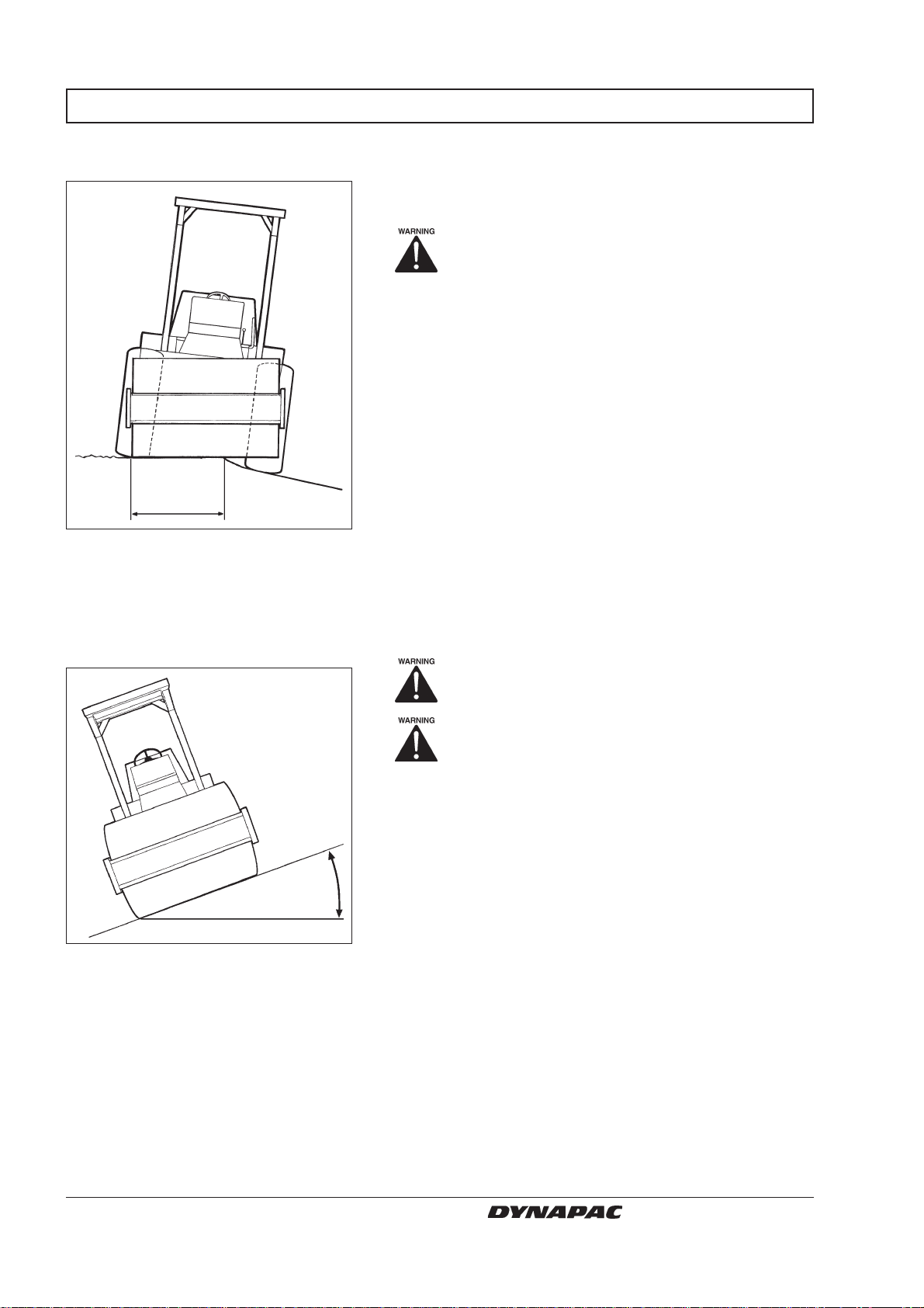
SAFETY WHEN DRIVING
Driving near an edge
At least
2/3
Fig. 1 Drum position when driving
near an edge
When you drive near an edge, at least two thirds of the
drum width must be on solid ground.
Remember that the machine’s center of
gravity is displaced outward when you
steer to one side. For example, it moves to
the right when you steer to the left.
Slopes
Max 20°
or 36%
Fig. 2 Tipping angle on side slopes
ROPS is always recommended when driving on slopes or insecure ground.
Wherever possible, avoid driving across a
slope. Instead, drive up and down on sloping ground.
The tipping angle is measured on level, hard ground
and a stationary machine. Steering angle zero, vibration switched OFF and all tanks full. Remember that
loose ground, steering of the machine, vibration switched ON, driving speed and raising the center of
gravity (as with accessories) may cause the machine
to topple even on a smaller slope than specified here.
4
CA121/141 O121EN4
SAFETY (OPTIONAL)
Strike-off blade
Fig. 3 Strike-off blade
The operator must make sure that nobody
is in the working area during operation.
Retract the strike-off blade to transportation
mode at the end of each working period.
Always lower the blade to the ground
before leaving/parking the roller.
CA121/141 O121EN4
5
SAFETY DECALS, LOCATION AND DESCRIPTION
532 7
11
14
8
6
12
12 7 10 2 3 1 17 5 6
8
6
12
9 1012 131
6
CA121/141 O121EN4

SAFETY DECALS, LOCATION AND DESCRIPTION
1.
Crush zone, articulation/
drum. Maintain a safe distance from the crush zone.
2.
Warning - rotating engine
components. Keep your
hands a safe distance from
the danger zone.
4.
Study the chapter about
towing before disengaging
the brakes. Danger of being
crushed.
5.
The operator is urgently
requested to read the safety
manual, and the operation
and maintenance instructions
before using the machine.
10.
904895
Lifting point
11.
Battery
disconnecter
12.
Securing point
13.
3.
Warning - very hot surfaces
in the engine compartment.
Do not touch.
7.
110 kPa
Tire pressure
15.
16 psi
991990
8.
Hoisting plate
6.
The articulation joint must be
locked while lifting. Read the
instruction manual.
Mass Kg
9.
Diesel fuel
14.
Handbook
compartment
13.
108
Sound Power level
CA121
13.
105
Sound Power level
CA141
Alt. 1 Alt. 2
791278
791275
= Optional
CA121/141 O121EN4
Hydraulic
fluid
Biological
hydraulic fluid
7

MACHINE AND ENGINE PLATES
Machine plate
1
Fig. 4 Left step
1. Machine plate
Serial number on frame
1
The machine plate (1) is affixed to the right side of the
steering column. The plate shows the manufacturer’s
name and address, type of machine, PIN (serial
number), weight in working order, engine power and
year of manufacture.
Please specify the roller’s PIN (serial number) when
ordering spares.
The machine’s serial number is punched on the right
edge of the forward frame. This number is identical with
the PIN (serial number) on the machine data plate.
Fig. 5 Front frame
1. Serial number
Engine plate
Fig. 6 Engine
1. Type plate
2. EPA sign (USA)
8
The engine data plate is on the right side of the engine,
close to the oil filter. The plate indicates the type of
engine, serial number and engine data. Please specify
the engine serial number when ordering spares. See
2
1
also the engine manual.
IMPORTANT ENGINE INFORMATION DEERE&COMPANY
*This engine is certified to run on Diesel Fuel. This engine conforms to XXXX
Model Year US EPA regulations on heavy-duty non road diesel cycle engine.
*Family No. xxxxx xx.xxxx*EU No.xxxx*97/68 xx*xxxx*xx
*Engine Model: 3029TF270. Displacement: 2.9L
*Valve Clearance: Intake 0.xxx mm Exhaust 0.xxx mm
*Fuel Rate: xx.x mm3/stroke @71 hp (53 kW) @2500 rpm
*Injection Timing: Ref:CTM. No Other Adjustments Required Rxxxxxx
John Deere Engine Manufacturing ISO 9001 Registered
For Engine Service and Parts Call 1-800-JD ENGINE
JOHN DEERE
Engine Serial Number
*CD3029TXXXXXX*
3029TF270 Abs.
DEERE&COMPANY MOLINE ILLINOIS MADE IN FRANCE
Coeff.
CA121/141 O121EN4

INSTRUMENTS AND CONTROLS
567 8
14
17
4
3
2
1
9
10
11
12
15
16
18
Fig. 7 Instruments and controls
1. Forward and reverse lever
2. Vibration ON/OFF
3. Reserve brake
4. Temperature gauge - coolant
5. Oil pressure gauge
6. Voltmeter
7. Fuel gauge
8. Tachometer/Hourmeter
9. Parking brake ON/OFF
CA121/141 O121EN4
13
10. Horn
11. Rev control
12. Starter switch
13. Pocket containing safety and
instruction manuals
14. Working lights ON/OFF
15. Strike-off blade UP/DOWN
16. Warning lamp, charging
17. Hazard beacon ON/OFF
18. Preheating ON/OFF
= Optional
9

INSTRUMENTS AND CONTROLS, FUNCTIONAL DESCRIPTION
Items Designation Symbol Function
in fig. 7
1 Forward and reverse lever Move the lever to the desired direction of
travel. Driving speed is proportional to movement of the lever. The roller brakes as the
lever is moved toward neutral. The engine
can only be started with the lever in neutral.
2 Vibration ON/OFF Switches vibration ON and OFF.
3 Reserve brake knob OFF (pulled out) is normal during operation.
(red knob) ON (pushed in) applies the brakes and
switches off the engine and electric power
supply. The F&B control must be restored to
neutral before restarting.
4 Temperature gauge, engine Indicates engine coolant temperature.
Normal gauge reading: 82–94°C. (180–
201°F) Above 99°C (210°F): Stop the engine
and determine the cause, see engine manual.
5 Oil pressure gauge Indicates engine oil pressure.
Normal indication: 140–415 kPa.
Below 100 kPa: Stop the engine and
determine the cause, see engine manual.
6 Voltmeter Indicates electrical system voltage.
Normal indication is 12–15 volts.
7 Fuel gauge Indicates level in the fuel tank.
8 Tachometer/Hourmeter Indicates current engine speed in RPM.
Multiply the gauge reading by 100. The
driving time is displayed digitally in hours.
9 Parking brake ON/OFF ON: Activates the parking brake.
OFF: Releases the parking brake. The
engine must be running before the parking
brake can be released.
10 Horn Press to honk the horn.
11 Rev control Released/engaged by the center button. Pull
out to increase engine revs. Push in to
reduce. Twist the handle for fine adjustment.
Counter-clockwise = increase, clockwise =
reduce. Minimum revs: 1000 r/min; Max:
2200 r/min.
10
CA121/141 O121EN4

INSTRUMENTS AND CONTROLS, FUNCTIONAL DESCRIPTION
Items Designation Symbol Function
in fig. 7
12 Starter switch In position
In position
controls are powered.
In position the start motor is activated.
13 Pocket for instruction manuals Manuals for safety, operating and
maintenance, which must not be removed
from the machine.
14 Working lights In ON mode, the four lamps in the ROPS
(Optional) arch will light.
15 Strike-off blade UP/DOWN/HOLD
UP/DOWN/HOLD(Optional)
16 Warning lamp, If the lamp lights while the engine is
battery charging running, the alternator is not charging.
Stop the engine and locate the fault.
17 Hazard beacon The rotating hazard flasher is on in ON
(Optional) mode.
18 Preheating button Press the preheating button for 30 seconds
before attempting to start the engine.
the electric circuit is broken.
all instruments and electric
CA121/141 O121EN4
11

BEFORE STARTING
Battery disconnecter
– Switching on
Fig. 8 Battery disconnecter
1. Handle
Operator’s seat – Setting
1
manual.
Make sure that the battery disconnecter (1) is switched
ON.
Lock the hood in the closed position with
the lever under the operator’s seat.
Position the operator’s seat so that the controls are
easily accessible.
Remember to perform daily service. See the operation
3
2
Fig. 9 Operator’s seat
1. Length adjustment
2. Seat-back setting
3. Cushioning adjustment
Instruments and controls
– Control
6
7
The seat can be adjusted as follows:
• Lengthwise (1).
• Seat-back slope (2).
• Cushioning in relation to the operator’s weight (3).
Always make sure that the seat is secure
before beginning operation.
1
Make sure that the reserve brake knob (3) is pulled out.
9
Turn the starter switch (12) to I. This powers up all
gauges and instruments.
The voltmeter (6) should indicate at least 12 volts.
The fuel gauge (7) should show a reading.
3
Fig. 10 Instrument panel
3. Reserve brake
6. Voltmeter
7. Fuel gauge
9. Parking brake knob
12. Starter switch
16. Warning lamp, charging
12
12
16
The warning lamp for charging (16) should light.
Make sure that the parking brake knob (9) is
in the applied mode.
If the parking brake is not applied, the roller
may start to roll when you start the engine
on sloping ground.
CA121/141 O121EN4

BEFORE STARTING
Seat belt
1
Fig. 11 Operator’s station
1. Seat belt
Always fasten the seat belt (1) that is provided if
ROPS is fitted on the roller, and wear a protective
helmet.
Always replace the seat belt (1) with a
new one if it is worn or has been subjected to a heavy load.
CA121/141 O121EN4
13

STARTING
Starting the engine
Set the forward and reverse lever (1) in neutral. The
8
engine can only be started in this mode.
6
5
4
2
1
Fig. 12 Instrument panel and controls
1. Forward/Reverse lever
2. Vibration control
4. Temperature gauge - coolant
5. Oil pressure gauge
6. Voltmeter
8. Tachometer/hourmeter
11. Rev control
12. Starter switch
18. Preheating knob (Optional)
11
12
18
Set the vibration control (2) to the OFF mode.
Pull up the rev control (11) to about 1/3 full throttle.
Hold the preheating button (18) pressed in for about 30
seconds (optional).
Turn the starter switch (12) to the right to start mode,
and release the knob as soon as the engine starts.
Do not run the starter motor too long. If the
engine does not start immediately, wait a
minute or so before making a new attempt.
Warm up the engine for a few minutes with the rev
control in the idling mode, longer if ambient temperature
is below +10°C (50°F).
Stop the engine immediately if the oil pressure
gauge does not show a reading within 15
seconds after starting.
Check while warming up that the voltmeter (6) indicates
13–15 volts, and that the coolant temperature gauge (4)
and the tachometer/hourmeter (8) give readings.
Remember that when you start and drive a
cold machine, the hydraulic fluid is cold and
the braking distance will be longer than
normal until the machine reaches normal
working temperature.
14
Make sure that ventilation (extraction) is
adequate if the engine is run indoors (risk of
carbon monoxide poisoning).
CA121/141 O121EN4
OPERATION
Under no circumstances may the machine
8
9
be operated from the outside. The operator
must remain seated inside the machine
during all operation.
5
4
3
1
Fig. 13 Instrument panel and controls
1. Forward/Reverse lever
3. Reserve brake
4. Temperature gauge - coolant
5. Oil pressure gauge
8. Tachometer/hourmeter
9. Parking brake
11. Rev control
11
Open the throttle (11) until engine speed is 2200 rpm on
the tachometer (8). Finely adjust by turning the control
knob – clockwise to reduce revs and counterclockwise to increase.
Check that the steering is working by turning the
steering wheel once to the left and once to the right,
while the roller is stationary.
Make sure that the area in front of and behind the roller is clear.
Move the toggle switch to the OFF position
to release the parking brake (9).
Be prepared because the roller may begin to
roll.
The reserve brake knob (3) must be pulled out.
Carefully move the forward and reverse lever (1) in the
desired direction of travel. The speed increases the
further the lever is moved from the neutral position.
Always regulate the speed with the forward and
reverse lever, not by changing the engine
speed.
Reserve brake – Check
3
Fig. 14 Instrument panel, left side
3. Reserve brake
CA121/141 O121EN4
Check while driving that the gauges show normal
values:
• Coolant temperature (4): 82–94°C (180–201°F)
(Above 99°C (210°F)—Stop the engine and locate the
fault.)
• Engine oil pressure (5): 140–415 kPa
(Below 100 kPa—Stop the engine and locate the fault.)
Test the reserve brake by pressing the
reserve brake knob (3) while the roller is
running slowly forward. Stop the roller and
identify the fault if the brake does not
work.
The engine stops when the reserve brake knob is
pressed. The control knob must be pulled out before
the engine can be restarted. The Forward/Reverse
control must be in neutral before the engine can be
restarted.
15

OPERATION/VIBRATION
Engaging the vibration
8
11
2
1
Fig. 15 Instrument panel and controls
1. Forward/Reverse lever
2. Vibration control
8. Tachometer/hourmeter
11. Rev control
Move the Forward/Reverse lever (1) forward or
backward.
Move the lever (2) to the ON position to engage vibration.
Never leave vibration on when the roller is
stationary. This may damage the surface and
the machine.
Compacting is usually done at 4–5 km/hour (6 1/2–8
mph) (normal walking speed). It is not necessary to
disengage vibration when changing the direction of
travel.
Move the lever (2) to the OFF position to disengage
vibration. Always switch off vibration before the roller
comes to a complete standstill.
OPERATION (OPTIONAL)
Operating the strike-off blade
15
Fig. 16 Instrument panel and controls
15. Lever
Optional
Make sure that the blade is at its uppermost
(raised) position before driving. Check the
state of the ground before using the blade.
The lever (15) has two modes.
Upward – Raising the blade.
Downward – Lowering the blade.
Lower the blade before leaving/parking the machine.
Use the blade only when driving FORWARD.
16
CA121/141 O121EN4

BRAKING
Normal braking and
reserve braking
3
9
Using the reserve brake
Normally you brake with the forward/reverse lever (1).
The hydrostatic transmission brakes the roller when
the lever is moved toward neutral. In addition there are
multi-disc brakes in the wheel motors that act as a
parking brake and are activated when the parking
brake (9) is applied.
1
Fig. 17 Instrument panel and controls
1. Forward/Reverse lever
3. Reserve brake knob
9. Parking brake
Normal braking
1
To brake in an emergency, press the reserve
brake knob (3), hold the steering wheel
firmly and be prepared for a sudden stop.
After braking, restore the forward/reverse lever to
neutral and pull up the reserve brake knob.
Remember that when you start and drive a
cold machine, the hydraulic fluid is cold and
the braking distance will be longer than
normal until the machine reaches normal
working temperature.
9
Move the lever (2) to the OFF position to disengage
vibration.
Move the forward/reverse lever (19) to neutral to stop
11
the roller.
Always activate the parking brake knob (9)
even for brief stops when on sloping
ground.
2
Turn back the rev control to idling. Always let the
engine idle for a few minutes to cool down.
Fig. 18 Instrument panel and controls
1. Forward/Reverse lever
2. Vibration ON/OFF
9. Parking brake
11. Rev control
CA121/141 O121EN4
Remember that when you start and drive a
cold machine, the hydraulic fluid is cold and
the braking distance will be longer than
normal until the machine reaches normal
working temperature.
17

BRAKING
Switching off
Fig. 19 Instrument panel and controls
12. Starter switch
12
Check the instruments to see if any faults are indicated, switch off all lights and other electrical functions.
Turn the starting knob (12) to position O. Lower the
instrument cover and lock it.
18
CA121/141 O121EN4

PARKING
Never leave the operator’s station with the
engine running unless the parking brake is
applied.
Make sure that the roller is parked in a safe
place for traffic. Chock the drum and wheels
if the roller is parked on sloping ground.
Remember the risk of freezing during the winter.
Fill the engine’s cooling system with antifreeze.
See also maintenance instructions.
1
Fig. 20 Chocking the drum and wheels
1. Chock
Battery disconnecter
Fig. 21 Battery disconnecter
1. Handle
The parking brake must always be set if the operator
has to leave his seat for any reason while the engine is
running. Another alternative is to use the reserve
brake, which also shuts down the engine.
1
Turn off the battery disconnecter (1) and remove the
handle before leaving the roller.
This will prevent the battery discharging and will also
make it difficult for any unauthorized person to start and
drive the machine. Lock the engine hood, too.
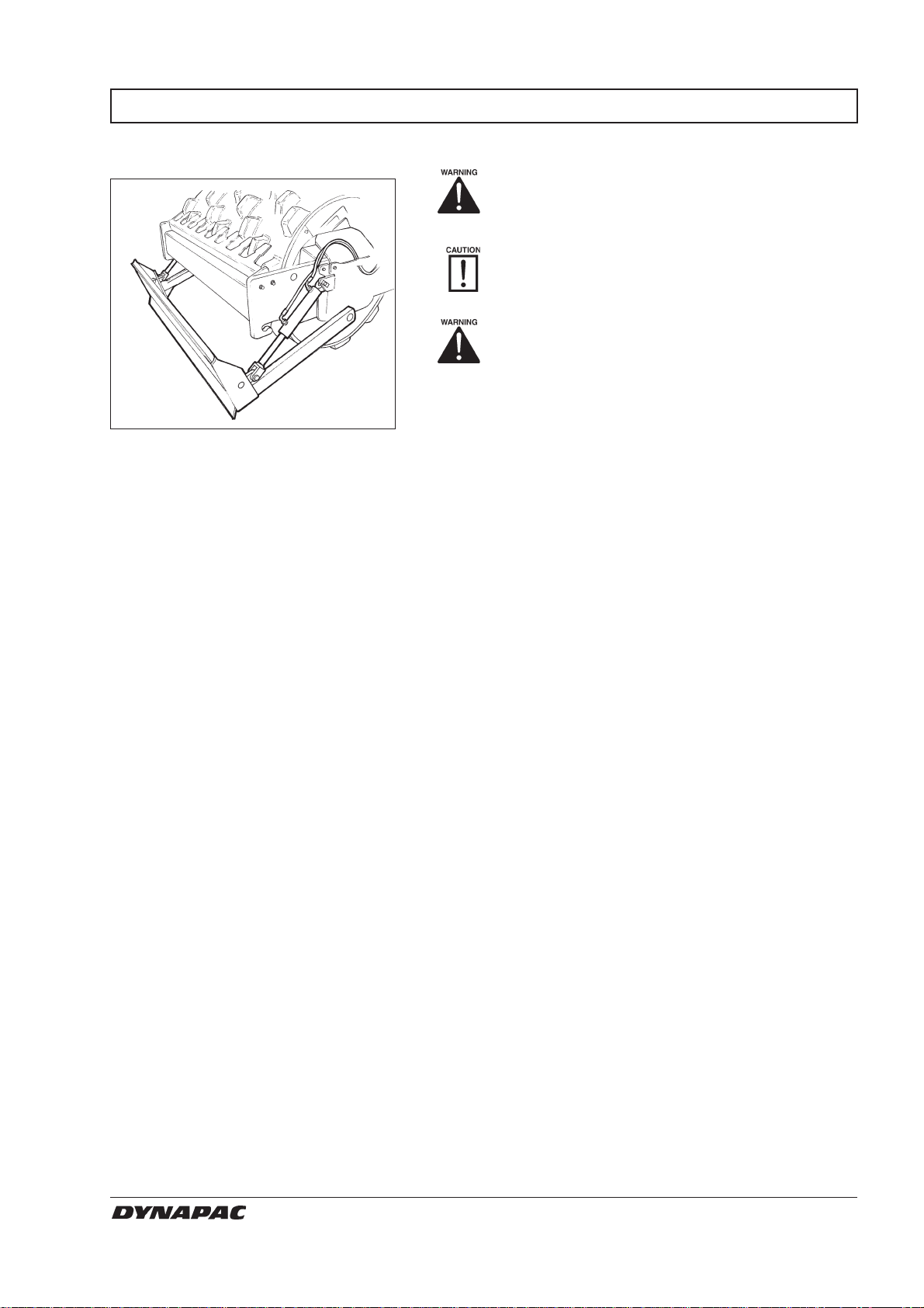
Strike-off blade (Optional)
Fig. 22 Strike-off blade
CA121/141 O121EN4
Always lower the blade to the ground
before leaving/parking the roller.
19

INSTRUCTIONS FOR LIFTING
Locking the articulation joint
12
Fig. 23 Left side of articulation
1. Articulation in interlocked mode
2. Cotter
The articulation must be locked to prevent
inadvertent turning before lifting the roller.
Turn the steering wheel so that the machine is set to
drive straight forward. Push the reserve brake knob.
Fold out the arm (1) and secure it to the rear machine
frame with the cotter (2). Attach the lifting chains and
ensure that no parts will be crushed when hoisting.
Weight: See data plate
on the roller
1
Fig. 24 Lifting the roller
1. Hoisting plate
Releasing the articulation joint
The maximum weight of the machine is
noted on the hoisting plate (1). See also
technical specifications in the maintenance
instructions.
Lifting gear, such as chains, steel wires,
straps, and lifting hooks, must be dimensioned
according to current regulations.
1
Keep well clear of the hoisted machine!
Make sure that hoisting hooks are securely
anchored.
Remember to restore the articulation interlock to
open mode before driving again.
2
Fig. 25 Left side of articulation
1. Articulation lock in open mode
2. Cotter
1
20
Release the cotter (2) and retract the locking arm (1).
Refit the cotter (2).
CA121/141 O121EN4

INSTRUCTIONS FOR TOWING
Alternative 1
Towing short distance with
engine working
2
Fig. 26 Drive pump
2. Disengagement screw (red)
Alternative 2
Towing short distance with
engine not working
Open the bypass valve on the right-hand side of the
drive pump by turning the red disengagement screw (2)
two whole turns counter-clockwise.
Start the engine and allow it to idle.
The roller can now be towed and can also be steered if
the steering system is in action.
The roller can be moved up to 300 yards according to
either of the options below.
1
Fig. 27 Wheel hub
1. Disengagement disc
TOWING/RETRIEVAL
Towing a roller
Fig. 28 Towing
Press the reserve brake knob to stop the
engine. Chock the drums to prevent the
machine from rolling.
Remove the disengagement discs (1) from both wheel
hubs and from the drum gearing. Reverse the discs
and screw them on with the raised part facing inward.
The roller must be counter-braked when
towing. Use a towbar, because the roller
will have no ability to brake.
The roller must be towed slowly (max. 3 km/h
(5 mph)) and only a short distance (max. 300
yds).
When towing/retrieval a machine, the towing
device must be connected to both lifting holes.
Pulling forces should act longitudinally on the
machine as illustrated. Maximum gross pulling
force 80 kN (18 lbf).
CA121/141 O121EN4
Restore all of the above towing items.
21

TRANSPORTATION
Roller prepared for
transportation
Interlock the articulation before hoisting
and transportation; follow the instructions
under the respective heading.
Secure the drum and wheels with chocks (1) and
anchor them to the transport vehicle.
Block up (2) under the drum frame to avoid overload on
the rubber suspension of the drum when lashing.
12
3
Fig. 29 Chocking the drum/frame
1.Chock
2.Block up
3.Lashing strap
3
Clamp down the roller with lashing strap at all four
corners; decals (3) indicate the fixing points.
Remember to restore the articulation interlock
to open mode before starting the roller again.
22
CA121/141 O121EN4

OPERATING INSTRUCTIONS – SUMMARY
1. Follow the SAFETY INSTRUCTIONS in the Safety Manual.
2. Make sure that all instructions in the maintenance manual are followed.
3. Turn the battery disconnecter to ON.
4. Make sure that the reserve brake knob is in OFF mode (pulled out).
5. Set the vibration lever in OFF mode.
6. Put the forward/reverse lever in neutral.
7. Pull out the rev control to 1/3.
8. Start the engine and let it warm up.
9. Set the rev control to working mode.
10. Drive the roller. Operate the forward/reverse lever with care.
11. Test the brakes.
Remember that the braking distance will be longer if the roller is cold.
12. Use the vibration only when the roller is in motion.
13. IN AN EMERGENCY: – Press the reserve brake knob.
– Grip the steering wheel firmly.
14. Parking: Press the emergency stop knob to stop the engine,
chock the drum and the wheels.
15. Lifting: See the operation manual.
16. Towing: See the operation manual.
17. Transport: See the operation manual.
18. Retrieval: See the operation manual.
CA121/141 O121EN4
23
 Loading...