

Page 1

VLAN Ethernet Switch
User’s Manual
Ver. 9.0
Dynamode Ltd
Page 2

1
Table of Contents
1. Brief Introduction of the product ----------------
2. Networking connection -----------------------
3. Connect with other Switch/Hub -------------
4. Application ------------------------------------
5. LED introduction -------------------------
6. Product Specification ----------------------
7. Management and software introduction ------
7-1 Status Menu --------------------------------
7-1-1 Overview --------------------------------
7-1-2 Port Status -------------------------------
7-2 Configuration Menu ----------------------
7-2-1 Port setting -------------------------------
7-2-2 Port trunking setting ------------------------
7-2-3 Overrall setting --------------------------
7-2-4 QoS setting ------------------------------
7-2-5 Priority Tag remove/insert ------------
7-2-6 VLAN overall setting ----------------7-2-7 VLAN setting
7-2-8 IGMP snooping------------
7-3 Security setting -----------7-4 Diagnostic function -------7-5 Reset to default configuration ---------
Dynamode Ltd
Page 3

2
7-6 Save configuration ---------------
1. Brief Introduction of the product
This is a 24 x 10/100Mbps + 2 x 10/100/1000Mbps managed
fast switch. This switch supports many advanced features like
supporting 10/100Mbps half/full duplexe auto negotiation,
MD/MDI-X auto sense, Port-VLAN and Tag-VLAN,
bandwidth control management ect.. It is an ideal choice for
users who are seeking for a higher standard networking
connection with a reasonable price.
2. Networking connection
Connect a device to the switch
When the switch is connected with a 10-base Tx device , pls
use UTP Cat 3 or 5 cable
The length of the cable should comply with the IEEE
standards and max. 100 meters (328ft)
If the switch has a Tx fibre port, you can use long range
fibre to connect the switch. The switch supports
MD/MDI-X auto sense, so you can use straight cable to
connect the workstation or another switch/hub.
Dynamode Ltd
Page 4

3. Connect with other Switch/Hub
The switch can connect with any 10Mbps or 100Mbps
switch/hub. Since all ports support MD/MDI-X auto sense, so
you can use straight cable or UTP cable to uplink the switch
through any port with other swit ch/hub.
4. Application
The switch can overcome the restriction of hub for uplink, and
improve the overall capacity and performance of the
networking. It can analyse the target address of the dada packet
to decide the forwarding destination of each packet. So the
switch can significately reduce the data flow in the networking.
3
Dynamode Ltd
Page 5

Below figure shows the segmentation ability of the switch. The
channel dispute of each node is reduced to the minimum, and
the usability of each port is efficiently improved.
5. LED introduction
LED indicator
LED indicators provide some useful information like status of
the switch and each port.
LED status introduction:
LED Name Status Description
4
Off No power Power
On Power on
On
There is a device linked to
the corresponding port but
no activity
Link/Act
Flash
There is an active device
linked to the corresponding
port
On The device in 100Mbps 100M bps
Off The device in 10Mbps
Dynamode Ltd
Page 6

5
On Transfer in full duplex Duplex
Off Transfer in half duplex
Giga port LED status introduction
6. Product Specification
-STANDARDS:IEEE802.3 10BASE-TxIEEE802.3u 100BASE
-Tx, IEEE802.3ab 1000BASE-Tx, IEEE802.1p,
IEEE802.1Q
-RATE: 10/100/1000Mbps RJ-45
-MODE: full/half duplex
-MEDIA: 10BASE-Tx UTP Cat 3,4,5; 100BASE-Tx UTP
Cat 5; 1000BASE-Tx UPT Cat 5e.
-PANEL LED: Power, Link/Act, 100Mbps, Duplex
-PORTS: 24 ports 10BASE-Tx/100BASE-Tx RJ45, 2
1000BASE-Tx RJ45
MDI-X/MDI: Auto sense
VLAN: Yes
QoS: Yes
TRUNK: Yes
Bandwidth Control: Yes
7. Management and software introduction
This switch support VLAN, Trunk, QoS, Ports
configuration (enable/disable, auto negotiation, half/full duplex,
flow control) ect. networking management functions. It can be
managed by management software through serial port(RS-232)
or browser.
Management through console port
Dynamode Ltd
Page 7

Before the management, pls follow below steps:
1. Connet the switch console port with the PC serial port
(RS-232) through the cable enclosed.
2. Run the hyper terminal software of the windows. If your
PC hasn’t installed the hyper terminal software, pls
install it under “ control panel ----> add/delete software
---> Windows installation software ----> Communication
---> Hyper terminal” (Windows 98). For Windows 2000
the hyper terminal is intalled by default.
3. Input the name for the connection in the new link
dialogue.
4. Set the COM port according to the PC main board
( usually COM1).
6
Dynamode Ltd
Page 8

5. Serial port settings:
Bit rate: 19200bps
Data location: 8
Parity check: None
Stop bit: 1
Flow control: None
7
Dynamode Ltd
Page 9

After setting, switch on the power of the switch. The
software starts and enter into the log interface below:
Note:
If the hyper terminal interface has disorder words or no
reaction, pls check the serial port property settings, and if
the serial port is correctly connected or if the power of
the switch is on.
Input any key to enter into the main menu. See below
figure:
8
Dynamode Ltd
Page 10

Note:
When you finished the settings /configuration, pls choose
“save” to save them. After finishing all settings, restart
the switch to effect the settings.
Key explanation:
Digital keys: choose the relative option;
F : Refresh the current page;
There are 6 options on the main menu, for details pls see
below:
7-1 Status Menu
See figure below:
9
Dynamode Ltd
Page 11

Explanation:
Overview: Overview the status of the switch
Port Status: Show status of the ports
Key “0”: return to the previous page
7-1-1 Overview
See figure below:
10
Dynamode Ltd
Page 12

Explanation:
1. Input “E”, enter into switch name change
2. after change, press “enter” key to confirm
7-1-2 Port Status
100M ports:
1000M ports:
11
Dynamode Ltd
Page 13

Explanation:
Digital key “1”: PageUP
Digital key “2”: PageDown
“Speed”: Show the ports speed
“Duplex”: Show status of half/full duplex of the port
“Link”: Show Link status of the port. Up means link,
Down means not link.
“Flow Control”: Port flow control status. Enable
means open, Disable means close.
“Auto Negotiation”: Port auto negotiation status.
“Enable” means open, Disable means close
“Trunk”: Shows if the port is in any Trunk group
7-2 Configuration Menu
See figure below:
12
Dynamode Ltd
Page 14

7-2-1 Port setting
See figure below:
13
Dynamode Ltd
Page 15

Explanation:
“I/M/J/L”: Up/Down/Left/Right seperately
“Space”: Change the chosen option
“R” Key: Restart and set to auto negotiation mode
“Enable”: Port Enable/Disable setting. “Enable” is open,
“Disable” is close.
“Speed advertisement”: Port connection speed and
full/half duplex settings.
“100M Full” means 100Mbps/Full duplex
“100M Half” means 100Mbps/Half duplex
“10M Full” means 10Mbps/Full duplex
“10M Half” means 10Mbps/Half duplex
“1000M Full” means 1000Mbps/Full duplex
“Flow Control”: Port flow control settings
“Enable” means flow control is enabled
“Disable” means flow control is disabled
14
“Tx Only” means only enable flow control for
Dynamode Ltd
Page 16

15
port transmitting package
“Rx Only” means only enable flow control for
port receiving package
“Symmetric” means balance flow control for
the ports
“Rx Bandwidth”: Receiving bandwidth control
“Non-control”: no bandwidth control
“128Kbps”: the port can only transmission data
at 128Kbps bandwith
“256Kbps”: the port can only transmission data
at 256Kbps bandwith
“512Kbps”: the port can only transmission data
at 512Kbps bandwith
“1Mbps”: the port can only transmission data at
1M bps bandwith
“2Mbps”: the port can only transmission data
at 2M bps bandwith
“4Mbps”: the port can only transmission data
at 4M bps bandwith
“8Mbps”: the port can only transmission data at
8M bps bandwith
“Tx Bandwidth”: Transmisstion bandwidth control
(settings same as above)
7-2-2 Port trunking setting
Port trunking is mainly used for improve the uplink
Dynamode Ltd
Page 17

bandwith for two switches connection. The switch
support non-dynamic load-balance distribution mode
based on port.
Non-dynamic load-balance distribution mode based
on port should be assigned each port flow to the
appointed trunking port according to the actual port flow
in accordance with the principal of average to improve
the bandwidth. The assighment principal is according to
the sequence of the port number averagely.
Note:
This switch is already preset 8 trunk group. The user
can choose to enable the relative Trunk group according
to actual requirement.
7-2-3 Overrall setting
See below figure:
16
Dynamode Ltd
Page 18

Explanation:
“Half Duplex Back Pressure Flow”
“Broadcast Storm Filtering Control”
“Loop Detect”
7-2-4 QoS setting
QoS function provide two internal sequence system
to support two different level of communication. High
priority and Low priority. The dada flow with High
priority has more short delay with the internal process
of the switch, reduce the time waiting maximumly for
some delay sensitive communication.
See figure below:
17
Dynamode Ltd
Page 19

Explanation:
“TOS/Diff Serv. Priority”: Enable/Disable
“802.1p Priority”: 802.1p Enable/Disable
“Adapted Flow Control”: If Enable this functi on, during
data transmission, if the port priority is setted High,
the flow control of the port will be disabled
automatically; If the port priority is setted Low, the
flow control of the port will be Enabled
automatically.
“Priority Weighted Ration (High: Low)”: The firmware
preseted 4 kinds of priority, 1:0, 4:1, 8:1, 16:1
seperately. The user can set it according to their
requirement.
Note:
The priority of static port is higher than 802.1p and
OS/Diff Serv.
18
Dynamode Ltd
Page 20

7-2-5 Priority Tag Insert/Remove
See figure below:
802.1Q VLAN tag principle:
Behind the original MAC address, 4 octet tag
will be inserted. If the Ether type of data package is
0 x8100, it means this data package include
IEEE802.1Q/802.1p tag. In the tag, except for the
above mentioned 2 octet, there are 3 bit priority
information, 1 bit CFI information (Canonical
Format Identifier, used to compress the Token Ring
data package, so it can transmission in the Ethernet),
12 bit VLAN ID(VID). 3 bit priority information is
for 802.1p, VID is identifier of VLAN for 802.1Q.
Since there are 12 bits for VID, so it can set 4094
VLAN.
19
Dynamode Ltd
Page 21

20
Insert tag ahead the data package, the data
package will increase 4 octet, the information in the
original data package will not change.
EtherType and VLAN ID insert behind the
MAC address (MAC source address), but ahead the
original Ethertype/Length or Logical Link Control.
Since the present data package is longer than the
original, so the CRC(Cyclic Redundancy Check)
should be recount.
Explanation:
“Don’t touch”: Not control to the 802.1Q VLAN
member.
“Remove Tag”: After Enable this, Tag information for
802.1Q VLAN member will be removed.
“Insert Tag (high-priority only)”: After Enable this,
It will insert a tag to the ports with High
priority of the 802.1Q VLAN member.
“Insert Tag (all frame)”: After enable this, it will
insert a tag to all ports of the 802.1Q VLAN
member.
7-2-6 VLAN overall setting
See figure below:
Dynamode Ltd
Page 22

Explanation:
“VLAN Function”: Enable/Disable VLAN
“Unicast Packet Inter-VLAN Leaky”: Enable/Disable
“ARP broadcast Packet Inter-VLAN Leaky”:
Enable/Disable
“IP Multicast Packet Inter-VLAN Leak”:
Enable/Disable
“802.1Q VLAN tag aware”: Enable/Disable
“Ingress Rule for Acceptable frame types”:
Clasify rules for received frame within
one VLAN
“Admit all Frames”
“Admit only VLAN-Tagged Frames”
“Ingress Rule for Ingress Filtering”:
Enable/Disable
21
Dynamode Ltd
Page 23

22
7-2-7 VLAN setting
Virtual Local Area Network (VLAN) is a logical
networking toplogical setting and not a physical
networking design. VLAN can segment the networking
into several broadcasting group logically. In this way, the
data packet can only transmission withing the VLAN.
You can consider a VLAN as a subnet. VLAN can
improve the overall performance and security of data
transmission for the networking.
VLAN connects the networking nods logically and
not physically. Through VLAN you can segment the
networking into several group without change the
physical connection of the devices.
For instance, you can segment the networking according
to below method:
According to department, like one VLAN for
Engineering department, one for Accounting
department and one for Sales department.
According to position levels, like one for directors,
one for managers and one for other staff.
According to users, like one for email users and one
for multimedia users.
Dynamode Ltd
Page 24

(一). Set up a Port Based VLAN group
See figure below:
Set up steps:
1. “E” to enter into the revise mode
2. “A” to set up a VLAN group
3. After creating a Port Base VLAN, appoint the
members belong to the VLAN group
4. Press “Enter” to confirm the set up.
23
Dynamode Ltd
Page 25

5. “O” to finish and escape the set up
6. Press “Save” to save the settings
(二)Set up a 802.1Q VLAN group
See figure below:
Set up steps:
1. “E” to enter into the revise mode
2. “A” to set up a VLAN group
3. After creating a Port Base VLAN, press “Space”
to return to “802.1Q VLAN”
4. Set VLAN ID and VLAN members for the group
5. Press “Enter” to confirm the settings
6. “O” to finish and escape the set up
7. Press “Save” to save the settings
(三)Delete a VLAN group
See figure below:
24
Dynamode Ltd
Page 26

Set up steps:
1. “E” to enter into the revise mode
2. “D” to delete a VLAN group
3. Choose the VLAN group you want to delete
4. “Y” to confirm the change
5. Press “Enter” to confirm the settings
6. “O” to finish and escape the set up
7. Press “Save” to save the settings
Note:
1.When using VLAN, pls Enable the VLAN function
under the VLAN overall setting
2.If there is no VLAN setup, all the ports are in the
same VLAN group.
Advice: Not use Port Base VLAN and 802.1Q VLAN at
the same time.
7-2-8 IGMP snooping
See figure below:
25
Dynamode Ltd
Page 27

“IGMP snooping”: Enable this function, it can
snoop the broadcasting informtin through this
7-3 Security setting
See figure below:
26
Dynamode Ltd
Page 28
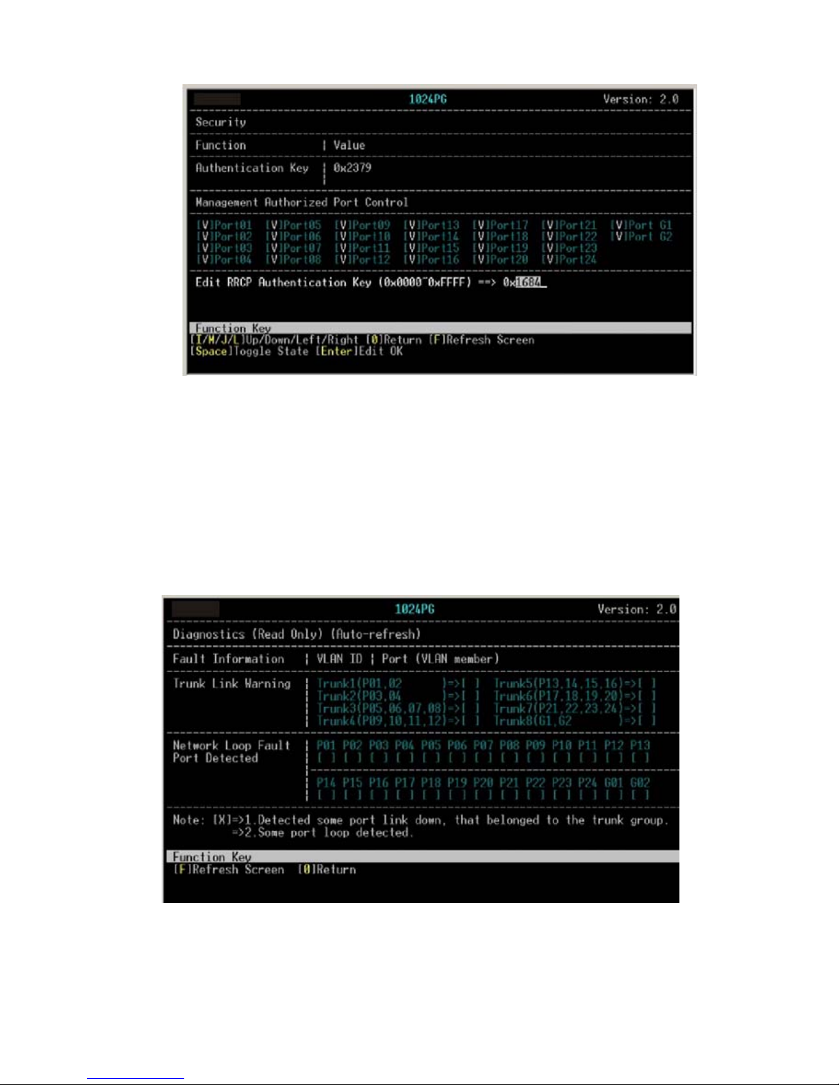
“Authentication Key”: In the “Value” volume input 4 keys.
Advice: If not necessary pls don’t change this value
7-4 Diagnostic function
See figure below:
“Diagnostics”: 1. To detect if any member within a Trunk
27
Dynamode Ltd
Page 29

group connect successfully. If not, it will
shows “x” in the “[]” within the Trunk group.
2. To detect if the port has any problem.
If the port can use properly, it will show “x”
in the relative “[]”
7-5 Reset to default configuration
See figure below:
“Load Factory Defaults”: If you choose this, the switch
will ask if your confirm the choice. Choose “Y”, the
switch will reset all the setting to the factory
defaults.
Note: This will delete all the user settings
7-6 Save configuration
See figure below:
28
Dynamode Ltd
Page 30

“Save”: After the switch settings, pls choose this option
to save the settings, the switch will ask if
confirm the choice, “Y” to confirm, “N” to
cancel.
29
Dynamode Ltd
 Loading...