


Dynamix UM-V2
VDSL2 LAN Extender
User Manual
Version 1.00
March 2009

Dynamix UM-V2 VDSL LAN Extender
User Manual, V100
Page: 1

Dynamix UM-V2 VDSL LAN Extender
User Manual, V100
Tables of Contents
Chapter 1 Introduction ...........................................................................3
1.1 Features ........................................................................................................................ 3
1.2 Specification .................................................................................................................. 3
1.3 Applications ................................................................................................................... 4
Chapter 2 Hardware Installation ....................................................................5
2.1 Front Panel............................................................................................................................... 5
2.2 Real Panel................................................................................................................................ 7
2.3 Installation................................................................................................................................ 7
Appendix I ......................................................................................................8
Connector Architecture ............................................................................................................... 8
Appendix II .....................................................................................................9
Chassis Accessory...................................................................................................................... 9
Page:2

Dynamix UM-V2 VDSL LAN Extender
User Manual, V100
Chapter 1 Introduction
Dynamix UM-V2 VDSL LAN Extender is a long reach Ethernet media converter with one
Ethernet port (RJ-45 connector) and one VDSL port (RJ-45 connector) It is a bridge mode
modem, well accommodating VDSL2 (Very-high-data-rate Digital Subscribe Loop)
technologies to extend Ethernet service over single-pair phone line. Supporting both
symmetric and asymmetric transmission, it can reach up to 100/75 Mbps bandwidth (line
rate) within 300M or 10/10 Mbps (line rate) for 1 Km long range connections. By providing
ultra-high speed, Dynamix UM-V2 VDSL LAN Extender makes your telephone line achieve
its best performance than before. It has the advantage of minimum installation time (simply
as plug-n-play) and minimum expense by allowing video streaming and data to share the
same telephone pair without interference.
1.1 Features
Ø Cost effective bridge function to connect two Ethernet LAN
Ø Support flow control on Fast Ethernet port via PAUSE frame or Back Pressure
Ø IEEE 802.1Q VLAN tag transparent
Ø Easy installation via simple plug-and-play
Ø Selectable CPE and CO mode via DIP switch:
Two working modes are built in the same unit, which keep the flexibility of
installation and easy provision of service but lower inventory of service provider.
Ø Selectable fast and interleaved mode:
Fast mode guarantees a minimum end to end latency less than1 ms. Interleaved
mode provides impulse noises protection for any impulse noise with a duration
less than 250 us, Interleaved mode has a maximum end to end latency of 10 m
sec. Interleaved mode is the default mode.
Ø Selectable target data rate and target SNR margin:
User has the ability to select fixed SNR margin (9 dB) or fixed target data rate.
When fixed SNR margin is selected, the systems will maintain the SNR margin at
9 dB across all usable loop length. When fixed target data rate is selected, the
system will lock the data rate up to 50 Mbps/30 Mbps whenever the calculated
SNR margin is higher than 9 dB. This gives best system stability and is the
default mode.
1.2 Specification
Ø LAN Interface:
RJ-45 connector
Complying with IEEE 802.3/802.3u/802.3x
10/100 Base-T Auto-Negotiation, Auto-MDI/MDI-X.
Ø VDSL Interface:
RJ-45 connector
DMT Encoding
Complying with ITU-T G993.1/993.2
On-board surge protection
Ø 4-position DIP Switch
Ø LED:
LAN: ACT/LNK, 10/100 Mbps, Half/Full Duplex
VDSL: Power On/Off, CO/CPE, Idle/Trained/Link
Ø Power supply:
DC single 12 Volt over 35mm DC jack
Ø Power consumption: 4.2 Watt maximum.
Ø Dimension: 95.5 x 69.4 x 22mm
Page: 3
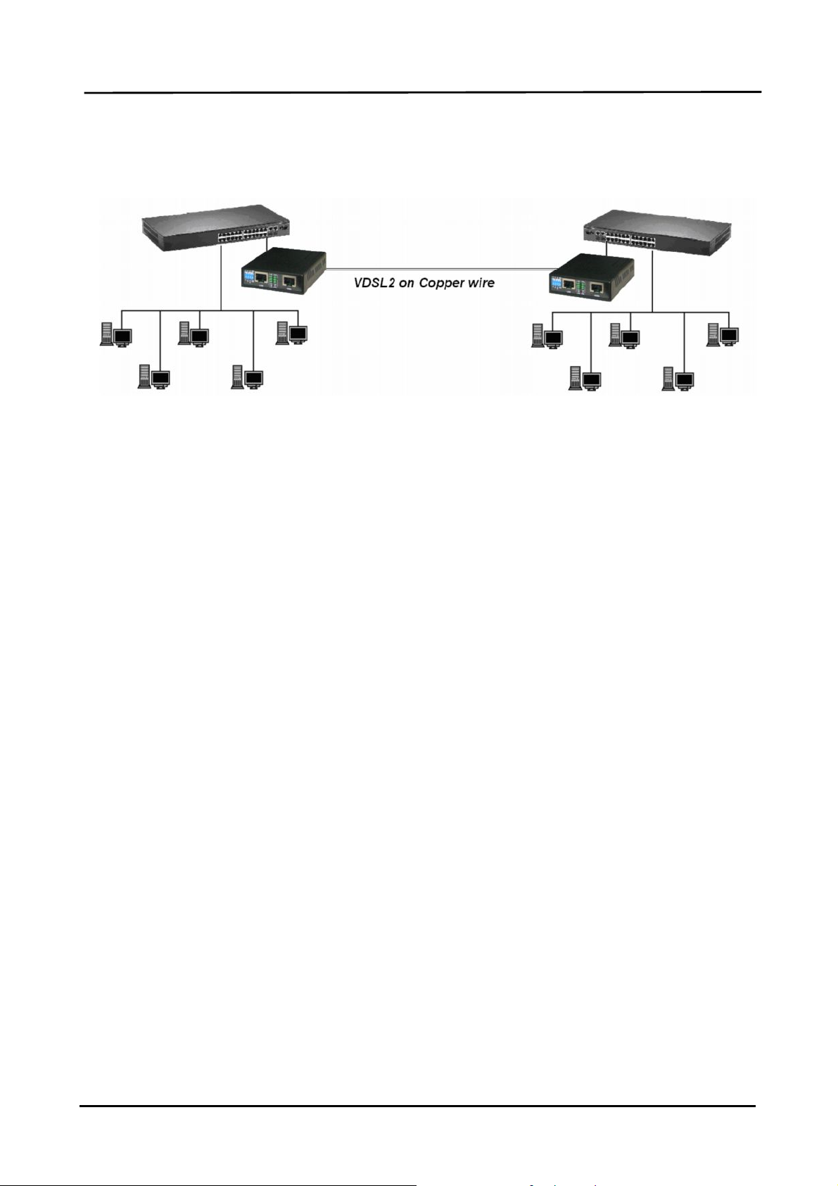
1.3 Applications
Dynamix UM-V2 VDSL LAN Extender
User Manual, V100
LAN Extender Application
Page:4

Dynamix UM-V2 VDSL LAN Extender
User Manual, V100
Chapter 2 Hardware Installation
This chapter shows the front panel and how to install the hardware.
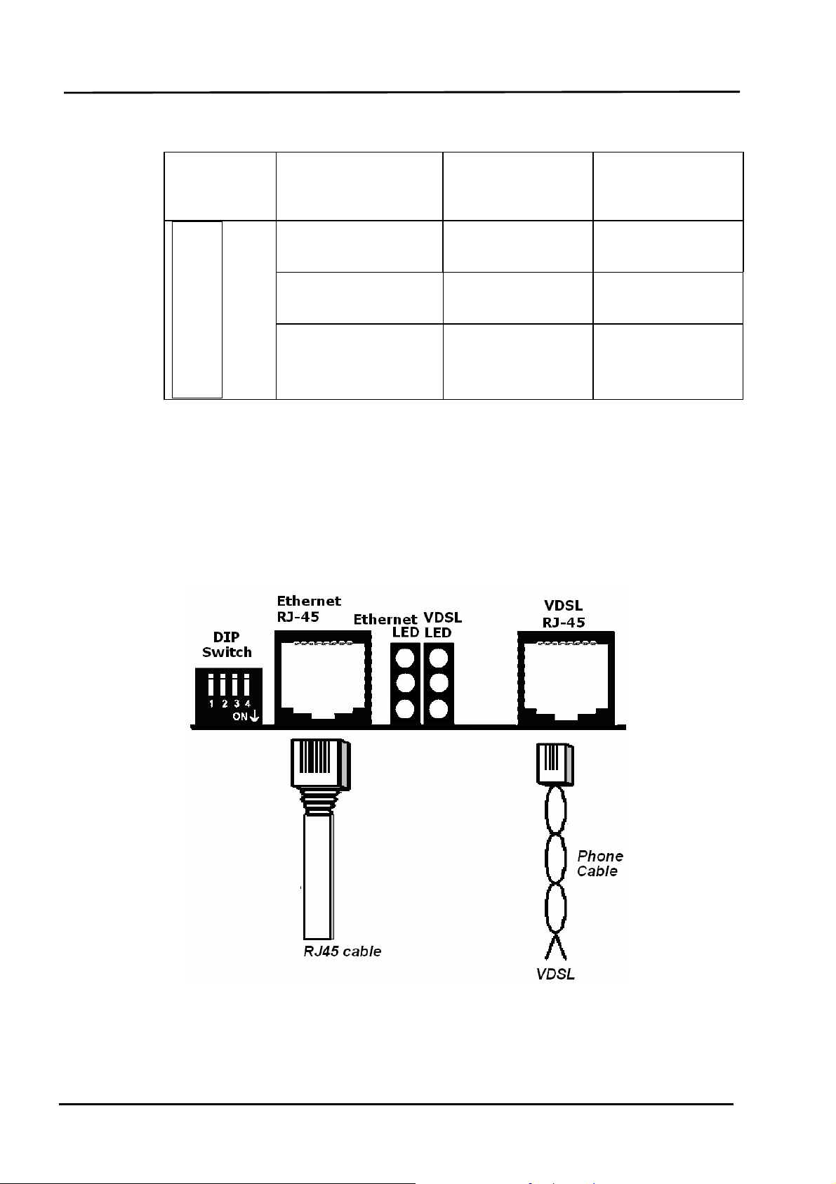
2.1 Front Panel
Please see the side view below configure 2.1:
Front panel can be separated into five parts fron left to right:
(1) DIP switch
(2) RJ-45 connector for Ethernet
(3) LEDs for Ethernet
(4) LED for VDSL
(5) RJ-45 connector for VDSL
1. The RJ-45 is designed to connect to the Local Network with the Unshielded
Twisted Pair (UTP) cable. The LEDs on top of RJ-45 connector show the status
below:
LED for
Ethernet
¡
®
Blinking
Activity Link UP Link Down
l
On
100Mbps 10Mbps
¡
Off
¡
Full Duplex Half Duplex
¡
Page: 5

Dynamix UM-V2 VDSL LAN Extender
User Manual, V100
2. The following table describes the DIP Switchs’ setting.
Pin 1 Pin 2 Pin 3 Pin 4
Side Channel Rate Limit SNR
Off CO Interleave Symmetric 9dB
On CPE Fast Asymmetric 6dB
Pin 1: CO, CPE switch
GO: LAN Extender acts as Central Office (CO) side.
GPE: LAN Extender acts as Customer Premise Equipment (CPE) side.
Pin 2: Impulse noise protection
Interleave mode: Provides communication protection for up to 250ms impulse noise
with latency less than 6 ms.
Fast mode: Direct data transmission with latency less than 1 ms.
Pin 3: Band Plan
Symmetric: Support the band plan G.997 and provide the symmetric transmission on
both down stream and upstream.
Asymmetric: Provides highest line rate in short range in asymmetric mode.
Pin 4: General protection
9dB: Better channel noise protection with SNR up to 9 dB
6dB: Original channel noise protection with 6 dB SNR.
Page:6
Dynamix UM-V2 VDSL LAN Extender
User Manual, V100
3. The following table describes the LEDs’ function of the product.
LED for
VDSL
¡
®blinking l On ¡ Off
Power ON Power OFF
CPE-mode CO-mode
¡
Slow: Idle
Linked Off line
¡
2.2 Real Panel
The DC Jack on the rear panel can be connected to power supply adaptor with the DC
input.
2.3 Installation
Please see the illustation below
Fast: Training
Page: 7

Appendix I
The Ethernet Port interface is a 8 position Modular Jack. The table below displays the
pin out assignments.
Pin Number Assignment (MDI-X) Figure
Dynamix UM-V2 VDSL LAN Extender
User Manual, V100
Connector Architecture
Ethernet Port Connector (RJ-45)
1
2
3
4
5
6
7
8
RX+; Receive data +
RX-; Receive data -
TX+; Transmit data +
Not used
Not used
TX-; Transmit Data -
Not used
Not used
1 8
1 8
Front View
Top View
VDSL Interface Pin Assignments (RJ-45)
The VDSL interface is standard eight-pin modular jack. The table below
displays the pin out assignments.
Pin Number Description Figure
1
2
3
Not used
Not used
Not used
4 ANALOG Input/Output
5 ANALOG Input/Output
6
7
8
Not used
Not used
Not used
1 8
1 8
Front View
Top View
Page:8

Dynamix UM-V2 VDSL LAN Extender
User Manual, V100
Appendix II
Chassis Accessory
Dynamix also provide the Mini-Chassis solution for application on the rack in CO side.
The major factor of Dynamix UR-V8 is listed below:
2 U high
Support 8-slot in one unit
Two units of mini-chassis are able to fit into the 19-inch standard rack to support 16-slot in
2U height., as the illustration below
Power Input: 90-230V AC, 47~63Hz
Embedded 10A/230V fuse.
Page: 9
 Loading...