

Dynamix UM-S4FB
Series rev.2
G.SHDSL .bis Router
User Manual
Version 0.06

Table of Contents
1
DESCRIPTIONS ................................................................................................................................. 3
1.1 FEATURES ........................................................................................................................................ 3
1.2 SPECIFICATION .................................................................................................................................. 4
2-WIRE G.SHDSL.BIS EFM ROUTER WITH 4 LAN PORTS ............................................ 6
4-WIRE G.SHDSL.BIS EFM ROUTER WITH 4 LAN PORTS ............................................ 6
1.3 APPLICATIONS................................................................................................................................... 7
2 GETTING TO KNOW ABOUT THE ROUTER ........................................................................................ 8
2.1 FRONT PANEL ................................................................................................................................... 8
2.2 REAR PANEL ..................................................................................................................................... 8
2.3 SHDSL.BIS LINE CONNECTOR ............................................................................................................ 10
2.4 CONSOLE CABLE.............................................................................................................................. 10
3 INSTALL THE ROUTER ..................................................................................................................... 11
3.1 CHECK LIST .................................................................................................................................... 11
3.2 INSTALL THE SHDSL.BIS ROUTER ........................................................................................................ 13
4 CONFIGURATION VIA WEB BROWSER ............................................................................................ 14
4.1 BASIC SETUP .................................................................................................................................. 16
4.1.1 Reference diagram ................................................................................................................. 19
4.2 STATU S ........................................................................................................................................ 21
4.2.1 Information ............................................................................................................................ 22
4.2.2 NETWORKING ........................................................................................................................ 22
4.2.3 PACKET STATISTICS ................................................................................................................. 23
4.2.4 G.SHDSL ................................................................................................................................. 23
4.3 ADVANCED SETUP ........................................................................................................................... 24
4.3.1 SHDSL.bis ............................................................................................................................... 24
4.3.2 WAN ....................................................................................................................................... 25
4.3.3 LAN ........................................................................................................................................ 27
4.3.4 DNS ........................................................................................................................................ 27
4.3.5 DHCP ...................................................................................................................................... 28
4.3.6 VLAN ...................................................................................................................................... 29
4.3.7 QoS ........................................................................................................................................ 30
4.3.8 RIP .......................................................................................................................................... 32
4.3.9 NAT/ D M Z ............................................................................................................................... 33
4.3.10 Virtual Server .................................................................................................................... 34
4.3.11 DDNS ................................................................................................................................. 34
4.3.12 FIREWALL .......................................................................................................................... 35
4.3.13 Content Filter .................................................................................................................... 36
4.3.14 IGMP ................................................................................................................................. 36
4.3.15 SNTP .................................................................................................................................. 37
Dynamix UM-S4FB Series rev.2 User Manual V0.06
1

4.4 ADMIN ........................................................................................................................................ 38
4.4.1 Security .................................................................................................................................. 38
4.4.2 Management ......................................................................................................................... 39
4.4.2.1 SNMP .......................................................................................................................................... 39
4.4.2.2 WWW ......................................................................................................................................... 40
4.4.2.3 TELNET ........................................................................................................................................ 40
4.4.2.4 SSH ............................................................................................................................................. 41
4.5 UTILITY ......................................................................................................................................... 41
4.5.1 SYSTEM LOG ........................................................................................................................... 42
4.5.2 System Tool ............................................................................................................................ 43
4.5.3 Upgrade ................................................................................................................................. 43
4.5.4 Restart ................................................................................................................................... 44
4.6 LOGOUT ...................................................................................................................................... 44
4.6.1 LAN-to-LAN connection with bridge Mode ............................................................................ 45
4.6.1.1 CO side ....................................................................................................................................... 45
4.6.1.2 CPE Side ...................................................................................................................................... 46
5 CONFIGURATION VIA SERIAL CONSOLE OR TELNET ........................................................................ 47
5.1 INTRODUCTION ............................................................................................................................... 47
5.1.1 Serial Console ........................................................................................................................ 47
5.1.2 Telnet ..................................................................................................................................... 47
5.2 MAIN MENU .................................................................................................................................. 48
5.3 KEY CLI COMMAND TREE OVERVIEW ................................................................................................... 49
Dynamix UM-S4FB Series rev.2 User Manual V0.06
2

1
1
DDeessccrriippttiioonnss
UM-S4FB Series 2/4-wire SHDSL.bis EFM Bridges/Routers comply with the latest G.SHDSL.bis
technology standards and supports symmetric data rate up to 15.3Mbps/Pair under TC-PAM 128.
Up to four pairs can be bonded together for aggregated bandwidth over 30.6 Mbps. It provides a
secure and symmetrical high-speed connectivity over existing copper-line infrastructure that is
ideal for service providers as well as SOHO and SME users.
UM-S4FB supports back to back connectivity for long reach Ethernet extension. Users can make
a direct connection betwe en two SHDSL.bis routers by using a standard tele phone cable, and
configure one as CO and the oth er as CPE. The c onnection offers a cost eff ective solution for
service providers and SME users who need high-speed dedicated network applications.
The SHDSL.bis EFM routers are integrated with high-end Bridging/Routing capabilities that
support flexible traffic management policies and Quality of Service, enabling business-class
Ethernet services with flexibility of mapping user traffic into Ethernet flows. The unit can be
managed by different ports and applications including comprehensive command-line interface
(CLI), Telnet, user-f r iendl y GUI-based Web Browser Interface and SNMP.
The SHDSL.bis routers help customers to meet their growing data comm unication needs by the
latest broadband technologies. Through the power of SHDSL.bis products, you can access
superior manageability and reliability.
11..1
1
FFeeaattuurreess
Symmetrical high-speed Ethernet service with SHDSL.bis, backward compatible with SHDSL
EFM bonding up to 30.6 Mbps (4-Wires, TC-PAM 128)
Support both EFM mode and ATM mode(1 PVC)
Support point to point connectivity
Support dying gasp
Dynamix UM-S4FB Series rev.2 User Manual V0.06
3

11..2
2
SSppeecciiffiiccaattiioonn
WA N Interface
SHDSL.bis: ITU-T G.991.2 (2004) Annex A/B/F/G supported
Support EFM Bon di ng and SHD SL M-Pair mode
Encoding scheme: TC-PAM 16/32/64/128
Data Rate:
N x 64 Kbps (N=3~89) using TC-PAM 16/32
Max. 5.696Mbps (1-Pair)
Max. 11.392Mbps (2-Pair)
N x 64 Kbps (N=3~239) using TC-PAM 64/128
Max. 15.296 Mbps (1-Pair)
Max. 30.592 Mbps (2-Pair)
Impedance: 135 ohms.
Compliant with IEEE 802.3ah
LAN Interface
4-Ports 10/100M Switch, Auto-negotiation for 10/100Base-TX and Half/Full Duplex,
Auto-MDIX Supported.
Bridging
Up to 1024 MAC address learning bridge
IEEE 802.1D transparent learning bridge
IEEE 802. 1Q / 1 P VLAN Por t -based/Tagging
QoS Class-based (Prioritization/Traffic/DSCP Mark), Rate Limiting, Up to 8 priority
queues
Routing
Support IP/TCP/UDP/ARP/ICMP/IGMP protocols
IP routing with static routing and RIPv1/RIPv2 (RFC1058/2453)
IP multicast and IGMP proxy (RFC1112/2236)
Network address translation (NAT/PAT) (RFC1631)
DHCP server, client and relay (RFC2131/2132)
DNS relay/proxy and caching (RFC1034/1035)
Dynamic DNS
IP precedence (RFC 791)
ATM
Multiple Protocols over AAL5
Ethernet over ATM (RFC 2684/1483)
1 PVC
EFM
EFM mode compliant to IEEE 802.3,
PPP over Ethernet (RFC2516)
Support of OAMPDU information and functionality ( ITU-T Y.1731)
OAMPDU Event Notification, Variable Request, Variable Response, Loopback Control
VLAN base QOS (802.1P/Q), Priority Queue
Dynamix UM-S4FB Series rev.2 User Manual V0.06
4

Network Protocol
VoIP(SIP) pass-through
IPv4 (ARP/RARP, TCP/UDCP, ICMP)
SNTP (Time Zone/ Daylight Savings)
Security
Natural NAT/PAT firewall
DMZ host
Virtual server mapping (RFC1631)
Advanced stateful packet inspection (SPI) firewall Denial of Service (DoS)
Application level gateway for URL and keyword blocking (Content Filter)
Access Control List (ACL)
Support PAP/CHAP/MS-CHAP client
Management
Web-based GUI for quick setup, configuration and management
Command-line interface (CLI) for local console and Telnet/SSH access
Password protected management and access control list for administration
Remote m anagement via WWW/SSH/Telnet local/remote
Real-time system log logging
SNMP SNMPv1/SNMPv2 (RFC 1157/1901/1905) and MIB-II (RFC 1213/1493)
Software upgrade via Web-browser/CLI, supported TFTP/FTP
Dying Gasp
Diagnostics/Monitoring
Routing Table
Packet Statistics
Hardware Interface
WAN: RJ-45 x 1
LAN: RJ-45 x 4
Console Port: RS232 female
Reset Button: Load factory default
Power Jack
Indicators
System: PWR, ALM
WAN 1~4: LNK/ACT
LAN 1~4: LINK/ACT
Physical / Electrical
Dimensions: 18.7 x 3.3 x 14.5cm (WxHxD)
Power: 100~240VAC (via power adapter)
Power Consumption: 9 watts Max
Operating T e mperature: 0~45°C
Storage Te mperature: -20°C~70°C
Humidity: 0%~95%RH (non-condensing)
Dynamix UM-S4FB Series rev.2 User Manual V0.06
5

Memory
128MB Flash Memory, 64MB DDR2 DRAM
Regulatory
CE
FCC Part 15 Class A
VCCI
EN60950
*We reserves the right to change specifications without prior notice.
Products’ Information
UM-S4FB 2-Wire G.Shdsl.bis EFM Router with 4 LAN Port
UM-S4FB/4w 4-Wire G.Shdsl.bis EFM Router with 4 LAN Ports
Dynamix UM-S4FB Series rev.2 User Manual V0.06
6

11..3
3
AApppplliiccaattiioonnss
Combination with EFM or ATM DSLAM
Point-to-point connection
.
Dynamix UM-S4FB Series rev.2 User Manual V0.06
7

2
2
GGeettttiinngg ttoo kknnooww aabboouutt tthhee rroouutteerr
This chapter introduces the main features of the router.
22..1
1
FFrroonntt PPaanneell
The front panel contains LEDs which show status of the router.
LED status of SHDSL.bis Router
LEDs Active Description
PWR
On
The power adaptor is connected to this device
DSL
WAN
LINK 1
On
SHDSL.bis line 1 connection is established
Blink
SHDSL.bis line 1 handshake
Transmit or received data over SHDSL.bis link 1
LINK 2
On
SHDSL.bis line 2 connection is established
Blink
SHDSL.bis line 2 handshake
Transmit or received data over SHDSL.bis link 2
LAN
LINK/ACT1
On
Ethernet cable is connected to LAN 1
Blink
Transmit or received data over LAN 1
LINK/ACT2
On
Ethernet cable is connected to LAN 2
Blink
Transmit or received data over LAN 2
LINK/ACT3
On
Ethernet cable is connected to LAN 3
Blink
Transmit or received data over LAN 3
LINK/ACT4
On
Ethernet cable is connected to LAN 4
Blink
Transmit or received data over LAN 4
ALM
On
SHDSL.bis line connection is dropped
Blink SHDSL.bis self-test
Off
No Alarm
22..2
2
RReeaarr PPaanneell
The rear panel of SHDSL.bis router is where all of the connections are made.
Dynamix UM-S4FB Series rev.2 User Manual V0.06
8

Connectors Description of Dynamix UM-S4FB
DC-IN
LAN (1,2,3,4)
Power adaptor inlet: Input voltage 12VDC
Four Ethernet10/100BaseT auto-sensing and auto-MDI/MDIX for LAN ports
(RJ-45)
CONSOLE
RS- 232C (DB9) for system configuration and maintenance
LINE
SHDSL.bis interface for WAN port (RJ-45)
RST
Reset button for reboot or load factory default
!
The reset button can be used only in one of two ways.
(1) Press the Reset Button for 1 second to make the system reboot.
(2) Pressing the Reset Button for 4 seconds will make the system load the factory default
settings and lose your ex isting conf iguration. W hen you want to c hange its c onfiguration b ut
forget the user nam e or password, or if the product is having problem s connecting to the
Internet and you want to configure it again by clearing all config urations, press the Reset
Button for 4 seconds with a paper clip or sharp pencil.
Dynamix UM-S4FB Series rev.2 User Manual V0.06
9

22..3
3
SSHHDDSSLL..bbiiss LLiinnee CCoonnnneeccttoorr
Below figure show the SHDSL.bis line cord plugs pin asignment:
22..4
4
CCoonnssoollee CCaabbllee
Below figure show the cosole cable pins asignment:
Pin Number
Description
Figure
1
No connection
12345
6789
2
RxD (O)
3
TxD (I)
4
No connection
5
GND
6
No connection
7
CTS (O)
8
RTS (I)
9
No connection
Dynamix UM-S4FB Series rev.2 User Manual V0.06
10

3
3
IInnssttaallll tthhee RRoouutteerr
This chapter will guide you to install the SHDSL.bis Router via Web Configuration and Serial
Console. Please follow the instructions carefully.
Note: There are three methods to configure the router: Serial console, Telnet or Web Browser.
Only one configuration method is used to setup the Router at any given time. Users have to
choose one method to configure it.
For Web configuration, you can skip item 3.
For Serial Console Configuration, you can skip item 1 and 2.
33..1
1
CChheecckk LLiisstt
(1) Check the Ethernet Adapter in PC or NB
Make sure that Ether net Adapter had been installed in PC or NB used for configuration of the
router. TCP/IP protocol is necessary for web configur ation, so please check the TCP/IP protocol
whether it has been installed.
(2) Check the supported Web Browser in PC or NB
In order to set up the rout eter by Web Configuration, your PC or notebook computer needs to
install the supported web browser
(3) Check the Terminal Access Program
For Serial Console and T elnet Configuration, users need to setup the term inal access program
with VT100 terminal emulation.
(4) Determine Connection Setting
Users need to know the Inter net Protocol supplied by your Service Provid er and determine the
mode of setting.
Protocol Selection
RFC1483
Ethernet over ATM
RFC1577
Classical Internet Protocol over ATM
RFC2364
Point-to-Point Protocol over ATM
RFC2516
Point-to-Point Protocol over Ethernet
Dynamix UM-S4FB Series rev.2 User Manual V0.06
11

The difference Protocols need to setup differ ence WAN parameters. After knowing the Protocol
provided by ISP, you have to ask the necessary WAN parameters to setup it.
Bridge EoA
Route EoA
PPPoE
VPI:
VCI:
Encapsulation:
IP Address:
Subnet Mask:
Gateway:
DNS Server:
VPI:
VCI:
Encapsulation:
Gateway:
Host Name:(if applicable)
VPI:
VCI:
Encapsulation:
User Name:
Password:
DNS Server:
Host Name:(if applicable)
Dynamix UM-S4FB Series rev.2 User Manual V0.06
12

33..2
2
IInnssttaallll tthhee SSHHDDSSLL..bbiiss RRoouutteerr
!
To avoid possible damage to this Router, do not turn on the router before Hardware Installation.
Connect the power adapter to the port labeled DC-IN on the rear panel of the product.
Connect the Ethernet cable.
Note: The r outer supp orts auto-MDI/MDIX switch in g so both s traight thr oug h and c ross -over
Ethernet cable can be used.
Connect the phone cable to the router and the other side of phone cable to wall jack.
Connect the power adapter to power source inlet.
Turn on the PC or NB, which is used for configuration the Router.
SHDSL.bis 4-ports router with complex network topology
Dynamix UM-S4FB Series rev.2 User Manual V0.06
13

4
4
CCoonnffiigguurraattiioonn vviiaa WWeebb BBrroowwsseerr
OVERVIEW
The web configuration is an HTML-based management interf ace for quick and easy set up of the
SHDSL.bis Routers by using an Internet browser.
After properly connecting the hardware of SHDSL.bis router as previously explained. Launch
your web browser and enter http://192.168.0.1 as URL
The default IP address and sub net-mask of the Router is 192.168.0.1 and 255.255.255.0.
Because the router acts as DHC P server in your network, the r outer will automatically assi gn IP
address for PC or NB in the network.
Type User Name root and Password root and then click OK.
The default user name and password both is root. For the system security, suggest changing them
after configuration.
Note: After changing the User Name and Password, strongly recommend you to save them
because another time wh en you login, the User Name and Password have to be used the
new one you changed.
Dynamix UM-S4FB Series rev.2 User Manual V0.06
14

Function Listing
Below is the full function list of G.Shdsl.bis router
BASIC
STATUS
• Information
• Networking
• Packet Statistics
• G.SHDSL
ADVANCED
• SHDSL.bis
• WAN
• LAN
• DNS
• DHCP
• VLAN
• QoS
• RIP
• NAT/DMZ
• Virtual Server
• DDNS
• Firewall
• Content Filter
• IGMP
• SNTP
ADMIN
• SECURITY
• MGMT
UTILITY
• SYSTEM LOG
• SYSTEM TOOL
• UPGRADE
• RESTART
LOGOUT
Dynamix UM-S4FB Series rev.2 User Manual V0.06
15

44..1
1
BBaassiicc SSeettuupp
OVERVIEW
Basic setup includes Bridg e and Routing operatio n modes. User can use it to s etup the Sh dsl.bis
router quickly. After completing it successfully, you can access Internet or use a pair of Shdsl.bis
Routers as LAN extenders. This is the easiest and quickest way to setup the router.
Click BASIC for basic installation.
G.SHDSL
Item
Description
Dynamix UM-S4FB Series rev.2 User Manual V0.06
16

Transfer Mode
Click on the drop-down lis t and selec t Transfer Mode as ATM (Asynchronous
Transfer Mode) or PTM (Packet Transfer Mode).
ATM uses asynchronous time-division multip lexing, and encodes data into
small, fixed-sized packets called cells.
SHDSL interfaces support Packet Transfer Mode (PTM). In PTM, packets (IP,
PPP, Ethernet, MPLS, and so on) are transported over DSL links as an
alternative to using Asynchronous Transfer Mode (A TM). PTM is based on the
Ethernet in the First Mile (EFM) IEEE 802.3ah standard.
*Note: This mode is changed, the system will need to reboot.
Pair Mode
Click on the drop-down list and select Pair Mode as Pair-1 or Pair-2.
Pair-1 for 2-Wire Shdsl.bis Router
Pair-2 for 4-Wire Shdsl.bis Router
STU Mode
Click on the drop-down list and select STU Mode as STU-C or STU-R
STU-C means the terminal of central office and STU-R means customer
premise equipment. For point to point application, STU-
C is the
server/master unit while STU-R is the client/slave unit.
Multiplexing
Click on the drop-down list and select Multiplexing used by your ISP as VC or
LLC.
VC-mux (VC-
based Multiplexing): Each protocol is assigned to a specific
virtual circuit. VC-
based multiplexing may be dominant in environments
where dynamic creation of large numbers of ATM VCs is fast and economical.
LLC (LLC-based Multiplexing): One VC carries multiple
protocols wit h protocol
identifying information be ing contained in each packet header. Despite
the
extra bandwidth and processing overhead, this method may be advantageous
if it is not practical to have a separate VC for each carried protocol.
*This is available only when you select ATM as Transfer Mode.
VPI
Enter the VPI (Virtual Path Identifier ) range from 0 to 255.
*This is available only when you select ATM as Transfer Mode.
VCI
Enter the VCI (Virtual Channe l Ide ntifier) range from 32 to 65535.
*This is available only when you select ATM as Transfer Mode.
WAN
Item
Description
Mode
Click on the drop-down list and select Mode as Routing or Bridge
Choose Routing if your ISP provides you with only one IP address and you
need several computers to use the same Internet account. C hoose Bridge
when your ISP provides you with more than one IP address and you need
several computers to
get individual IP address from your ISP’s DHCP server .
When Bridge is selected, NAT, DHCP server and Firewall become unavailable.
*Note: This mode is changed, the system will need to reboot.
Encapsulation
Click on the drop-down list and select Encapsulation used by your ISP as
PPPoE or RFC1483
WAN-IP
Item
Description
IP Address Type
Click on the drop-down list and select IP Address Type as Static or Dynamic
A static IP address is a fixed IP provided by your ISP . A dynamic IP address
is different every time when you connect to the Internet.
IP Address
Enter IP address for WAN when select Static IP address Type.
Submask
Enter a subnet mask in dotted decimal notation when select Static IP address
Type.
Gateway IP Address
Enter a gateway IP address provided by your ISP when select Static IP
address Type.
Dynamix UM-S4FB Series rev.2 User Manual V0.06
17

LAN
Item
Description
IP Address
Enter IP address for LAN
Subnet Mask
Enter a subnet mask in dotted decimal notation when select Static IP
address Type.
When select PPPoE as Encapsulation, you are required to enter the User Name and Password provided by your
IS P.
PPPoE
Item
Description
User Name
Enter User Name provided by the ISP for PPPoE
Password
Enter Password provided by the ISP for PPPoE
Click on Apply to save the parameters or Cancel to start configuring this page from beginning.
Dynamix UM-S4FB Series rev.2 User Manual V0.06
18

44..11..1
1
RReeffeerreennccee ddiiaaggrraamm
Bridge mode
When configured in Bridge Mode, the router will act as a pass-through device and allow the
workstations on your LAN to have public addresses directly on the internet.
EoA
EoA (Ethernet-over-ATM) protocol is com monly used to carry data b etween local area network s
that use the Ethernet protocol and wide-area networks that use the ATM protocol. Many
telecommunications industry networks use the ATM protocol. ISPs who provide DSL services
often use the EoA protocol for data transfer with their customers' DSL modems.
EoA can be implement ed t o prov i de a br idged connection betw ee n a DS L m ode m an d t h e I SP. In
a bridged connection, data is shared between the ISP's netw ork and their customer's as if th e
networks were on t he same physical LAN. Bridged connec tions do not use the IP protoco l. EoA
can also be configur ed t o p rovide a ro uted c onnect ion with the I SP, w hich us es t he I P prot ocol t o
exchange data.
Dynamix UM-S4FB Series rev.2 User Manual V0.06
19

PPPoE
PPPoE (point-to-point protocol over Ethernet) are authentication and connection protocols used by
many service provider s for broadband Internet acces s. These are specifications for con necting
multiple computer users on an Ethernet local area network to a remote site through common
customer premises equ ipment, which is the telep hone company's term for a mo dem and similar
devices. PPPoE can be us ed to office or b uilding . Users share a comm on Digital Subsc riber Line
(DSL), cable modem, or wireless connection to th e Internet. PPPoE combine th e Point-to-Point
Protocol (PPP), commonly used in dialup connections, with the Ethernet protocol or ATM protocol,
which supports multiple users in a local area network. The PPP protocol information is
encapsulated within an Ethernet frame or ATM frame.
Dynamix UM-S4FB Series rev.2 User Manual V0.06
20

44..2
2
SSTTAATTUUSS
OVERVIEW
STATUS allows you to monitor the current status of the SHDSL.bis Router including basic software
and hardware information, networking status, detailed packet statistics and G.SHDSL(WAN)
status.
Information
Basic Device Inf ormation including Host Name, HW MCSV, SW MCSV, Software
Version, MAC Address, Serial Number, DSL Chip information, System Time and
System Update Time.
Networking
Current status of Network, DSL and Route Table.
Packet Statistics
System Status and Packet statistics for WAN port and LAN port.
G.SHDSL
Mode, Line rate and P erformance inform ation including SNR margin, atteunation
and CRC error count.
Dynamix UM-S4FB Series rev.2 User Manual V0.06
21

44..22..1
1
IInnffoorrmmaattiioonn
STATUS > Information
INFORMATION page displays basic device information including Host Name, HW MCSV, SW
MCSV, Software Version, Ethernet MAC Address, Serial Number, DSL Chip Name, DSL Hardware
Pair Number, DSL Firmware Version, System Current Time and System Update Time.
44..22..2
2
NNEETTWWOORRKKIINNGG
STATUS > Networking
NETWORKING STATUS page displays Network Status, DSL Status and Route Table information
Dynamix UM-S4FB Series rev.2 User Manual V0.06
22

44..22..3
3
PPAACCKKEETT SSTTAATTIISSTTIICCSS
STATUS > Packet Statistics
PACKET STATUS page displays System Status and packet statistics for WAN port and LAN port.
44..22..4
4
GG..SSHHDDSSLL
STATUS > G.SHDSL
G.SHDSL STATUS page displays current status of DSL line including Channel Name, State,
Annex, TCLayer, Line Rate, SNR, Loop Attenuation, TxPower and CRC.
Dynamix UM-S4FB Series rev.2 User Manual V0.06
23

44..3
3
AAddvvaanncceedd SSeettuupp
OVERVIEW
Advanced setup includes SHDSL.bis, WAN, LAN, DNS, DHCP, VLAN, QoS, RIP, NAT/DMZ,
Virtural Server, DDNS, Firewall, Content Filter, IGMP and SNTP.
Note: The advanced functions are only for advanced users to setup advanced functions. The
incorrect setting of ad vanced functions will affect the performance or result system error, even
disconnection.
44..33..1
1
SSHHDDSSLL..bbiiss
ADVANCED>SHDSL.bis
Dynamix UM-S4FB Series rev.2 User Manual V0.06
24

Service Type
Item
Description
Pair Mode
Click on the drop-down list and select Pair Mode as Pair-1 or Pair-2.
Pair-1 for 2-Wire Shdsl.bis Router
Pair-2 for 4-Wire Shdsl.bis Router
Pair Config
Item
Description
Mode Type
Click on the drop-down list and select STU Mode as STU-C or STU-R
STU-C means the terminal of central office and STU-R means customer
premise equipment. For point to point application, STU-
C is the
server/master unit while STU-R is the client/slave unit.
Line Probe
Click on the drop-down list and select Enable to enable Line Probe or Disable
to disable Line Probe.
For adaptive mode, you have to Enable Line Probe function. The router will
adapt the data rate automatically according to the line status.
Note: The TCPAM-64/128 did not support Line Probe Disable.
Transfer Max Rate
Select the maximum rate for sending and receiving data.
Transfer Min Rate
Select the minimum rate for sending and receiving data.
Standard Mode
There are four Annex types: Annex A (ANSI), Annex B (ETSI), Annex AF and
Annex BG.
Select the Standard Mode supported by yo ur I SP.
For point to point applications, you may choose one of the four types
according to which line rate you need.
Modulation
Select the modulation supported by your ISP.
Click on Apply to save the parameters or Cancel to start configuring this page from beginning.
44..33..2
2
WWAANN
ADVANCED>WAN
Dynamix UM-S4FB Series rev.2 User Manual V0.06
25

General
Item
Description
Transfer Mode
Click on the drop-down lis t and selec t Transfer Mode as ATM (Asynchronous
Transfer Mode) or PTM (Packet Transfer Mode).
ATM uses asynchronous time-division multip lexing, and encodes data into
small, fixed-sized packets called cells.
SHDSL interfaces support Packet Transfer Mode (PTM). In PTM, packets (IP,
PPP, Ethernet, MPLS, and so on) are transported over DSL links as an
alternative to using Asynchronous Transfer Mode (A TM). PTM is based on the
Ethernet in the First Mile (EFM) IEEE 802.3ah standard .
Note: This mode is changed, the system will need to reboot.
Operation Mode
Click on the drop-down list and select Operation Mode as Routing or Bridge
Choose Routing if your ISP provides you with only one IP address and you
need several computers to use the same Internet ac count. Choose Bridge
when your ISP provides you with more than one IP address and you need
several computers to get individual IP address from your ISP’s DHCP server.
When Bridge is selected, NAT , DHCP server and Firewall become unavailable.
Note: This mode is changed, the system will need to reboot.
Encapsulation
Click on the drop-down list and select Encapsulation us ed by your ISP as
PPPoE or RFC1483
When select PPPoE as Encapsulation, you are required to enter the User
Name and Password provided by your ISP.
User Name
Enter User Name provided by the ISP for PPPoE
Password
Enter Password provided by the ISP for PPPoE
Service Name
Enter Service name for PPPoE
IP Address
Item
Description
IP Address Type
Click on the drop-down list and select WAN IP Address Type as Static or
Dynamic
A static IP address is a fixed IP provided by your ISP . A dynamic IP address
is different every time when you connect to the Internet.
IP Address
Enter IP address for WAN when select Static IP address Type.
Submask
Enter a subnet mask in dotted decimal notation when select Static IP address
Type.
Gateway IP Address
Enter a gateway IP address provided by your ISP when select Static IP
address Type.
Click on Apply to save the parameters or Cancel to start configuring this page from beginning.
Dynamix UM-S4FB Series rev.2 User Manual V0.06
26

44..33..3
3
LLAANN
ADVANCED>LAN
IP Setting
Item
Description
LAN IP
Enter IP address for LAN
Subnet Mask
Enter a subnet mask in dotted decimal notation when select Static IP
address Type.
Click on Apply to save the parameters or Cancel to start configuring this page from beginning.
44..33..4
4
DDNNSS
ADVANCED>DNS
DNS Server
Item
Description
First DNS Server
Click on the drop-down list and select below options for DNS Servers;
Obtained From ISP: Select this option when your ISP dynamically assigns
the DNS server information.
User Defined: Select this option when you have the IP address of a DNS
server.
DNS Relay: Select this option when your ISP uses IPCP DNS server
extensions and the SHDSL.bis Router acts as DNS proxy.
Second DNS Server
Third DNS Server
Dynamix UM-S4FB Series rev.2 User Manual V0.06
27

None: Select this option when you don’t want to configure DNS servers.
Click on Apply to save the parameters or Cancel to start configuring this page from beginning.
44..33..5
5
DDHHCCPP
ADVANCED>DHCP
DHCP
Item
Description
DHCP
Click on the drop-down list and select below options for DHCP;
None: Select this option to disable DHCP server.
Server: Select this option when the route r ca n assig n I P address e s . Then
enter the fields for IP Pool Starting Address, Pool Size and Lease Time.
Relay: Select this option the router will relay DHCP requests and responses
between the remote server and the clients. Then enter the field for Remote
DHCP Server.
IP Pool Starting Address
Enter the 1st address in the IP address pool.
*This field is required only when you enable DHCP server.
Pool Size
Enter the size of IP address pool.
*This field is required only when you enable DHCP server.
Lease Time
Enter the lease time for IP addresses.
*This field is required only when you enable DHCP server.
Client List
The table displays th e list a nd status of clients wit h their Host Nam e, State, IP address, MAC a nd
Expired Time.
Static DHCP
Item
Description
IP Address
Enter IP address to change the static DHCP setting
MAC Address
Enter the MAC address of the Ethernet device.
Static List
Dynamix UM-S4FB Series rev.2 User Manual V0.06
28

The table displays IP addresses and MAC added to the Static DHCP list.
Click on Apply to save the parameters or Cancel to start configuring this page from beginning.
44..33..6
6
VVLLAANN
VLAN (Virtual Local Area Net work) allows a physical net work to be parti tio ned int o multiple logical
networks. Devices on a logical network belong to one group. A device can belong to more th an
one group. With VLAN, a device cannot directly talk to or hear from devices that are not in the
same group.
With MTU (Multi-Tenant Unit) applications, VLA N is vital in pr o v iding is o lat ion and security among
the subscribers. When properly configured, VLAN pr events one subscriber from accessing the
network resources of another on the same LAN.
VLAN also increases network performance by limiting broadcasts to a smaller and more
manageable logical broadcast domain. In traditional switched environments, all broadcast packets
go to each every individua l port. With VLAN, all broa dcasts are confined to a specif ic broadcast
domain.
The IEEE 802.1Q defines the op erat ion of VLAN brid ges that permit the definition, operat ion, a nd
administration of VLAN topologies within a bridged LAN infrastructure.
The router supports two types of VLAN: 802.1Q Tag-Based VLAN and Port-Based VLAN.
VID: (Virtual LAN ID) It is an definite number of ID range from 1 to 4094.
PVID: (Port VID) It is an untagged member from 1 to 4094 of default VLAN.
ADVANCED>VLAN
Dynamix UM-S4FB Series rev.2 User Manual V0.06
29

VLAN Mode
Item
Description
Active Mode
Active 802.1Q VLAN function
On: Enable VLAN Configure
Off: Disable VLAN Configure
Group Config (Summary Table)
Item
Description
Name
This field displays the name of the VLAN group
VID
This field displays the ID number for a VLAN group.
MGMT
Specify the selected VLAN group as manageable.
Port Number
The columns display the VLAN settings on each port.
“Tag” for a tagged port.
“UnTag” for an untagged port.
“Not Group“for ports without VLAN settings.
PVID
This field displays the ID number of the VLAN group
Note: The LAN/WAN’s PVID need to belong to valid entry’s VID.
Click on Apply to save the parameters or Cancel to start configuring this page from beginning.
44..33..7
7
QQooSS
QoS is the func tion to decide the priorities of s etting IPs to trans fer packets under the situ ation of
overloading bandwidth. Use QoS set up for traffic management of the SHDSL.bis router.
ADVANCED>QoS
General
QoS
Item
Description
Active QoS
Active QoS for traffic management
WAN Management
Bandwidth
Specify the bandwidth allocated to WAN using QoS.
Matching the bandwidth to WAN’s actual speed is recommended.
Ethernet Priority & IP
Precedence
This field is not effective when traffic matches the class configured under
CLASS SETUP.
When select ON and traffic doesn’t match the class configured under CLASS
SETUP, the router assigns priority to unmatched traffic based on IEEE
Dynamix UM-S4FB Series rev.2 User Manual V0.06
30

802.1p priority level, IP precedence.
When select OFF, unmatched traffic is mapped to Queue Two.
Packet Length
This field is not effective when traffic matches the class configured under
CLASS SETUP.
When select ON and traffic doesn’t match the class configured under CLASS
SETUP
, the router assigns priority to unmatched traffic based on IEEE
802.1p priority level, Packet Length.
When select OFF, unmatched traffic is mapped to Queue Two.
Click on Apply to save the parameters or Cancel to start configuring this page from beginning.
CLASS SETUP
Click on Add to create a new class
Class Configuration
Item
Description
Active
Activate the classifier
Name
Enter the name of the classifier
Interface
Only from LAN Side for the traffic of the classifier
Priority
Assign priority to the traffic of the classifier
Order
Ordering number of the classifier
Tag Con figuration
Item
Description
DSCP Value
Select Same to keep the DSCP field in the packets.
Select Auto to map the DSCP value to 802.1 priority level automatically
802.1Q Tag
Select Same to keep the priority setting and VLAN ID of the frames.
Select Auto to map 802.1 priority level to the DSCP value automatically
Dynamix UM-S4FB Series rev.2 User Manual V0.06
31

Filter Configuration
Item
Description
Active
Activate the classifier
Name
Enter the name of the classifier
Interface
Select from WAN or from LAN for the traffic of the classif ier
Priority
Assign priority to the traffic of the classifier
Order
Ordering number of the classifier
Click on Apply to save the parameters or Cancel to start configuring this page from beginning.
44..33..8
8
RRIIPP
RIP (Routing Information Protocol) allows one router to exchange routing information with another.
ADVANCED>RIP
Click Modify to edit each entry information
RIP>Entry Config
Entry Config
Item
Description
Direction
Select Directions from:
Off: No RIP packets will be sent, and incoming RIP packets will be ignored
Both: Routing table will be broadca
sted periodically and incorporated
received information from both direction
In Only: Only RIP information received will be incorporated
Out Only: Only broadcast device’s routing table periodically
Dynamix UM-S4FB Series rev.2 User Manual V0.06
32

Version
Select from:
RIP-V1: Only sends RIP v1 messages only
RIP-V2: Sends RIP v2 messages in multicast and broadcast format
Auth Type
Select from (1)Simple (2)MD5
Auth Code
Enter the Corresponded Authentication Code for the Type picked above
Split Horizon
Enable or Disable Split Horizon feature
Click Apply to save the parameters changed or Back to return to previous page
44..33..9
9
NNAATT//DDMMZZ
NAT (Networ k Addres s Translation) is the trans lation of an I nternet Protocol address (IP address)
used within one ne twork to a different IP address known with in another networ k. One network is
designated the inside n etwork and the other is the outside. Typically, a company maps its local
inside network address es to one or more glob al outside IP addresses and reverse the gl obal IP
addresses of incoming packets back into local IP addresses. This ensure security since each
outgoing or incoming request must go through a translation process, that also offers the
opportunity to qualify or authenticate the request or match it to a previous request. NAT also
conserves on the nu mber of global IP addresses that a co mpany needs and l ets the company to
use a single IP address of its communication in the Internet world.
DMZ (Demilitarized zone) is a computer host or small network inserted as a “neutral zone”
between a company private network and the outside public network. It prevents outside users from
getting direct access to a server that has company private data.
In a typical DMZ configura tion for an enterprise, a separate comput er or host receives requests
from users within the private network to access via Web sites or other companies accessible on the
public network. The DMZ host then initiates sessions for these requests to the public network.
However, the DMZ host is not able to initiate a ses sion back into the private n etwork. It can only
forward packets that have already been requested.
Users of the public networ k outside the company can acces s only the DMZ host. The DMZ m ay
typically also have the company’s Web pages so these could serve the outside world. However, the
DMZ provides acces s to no other com pany data. In t he eve nt that an outside user penetrated t he
DMZ host’s security, the Web pages might be corrupt ed, but no other c ompany inf ormation woul d
be exposed.
ADVANCED>NAT/DMZ
NAT vs. DMZ Setup
Item
Description
NAT/DMZ Mode
Select to Enable or Disable NAT/DMZ mode
Dynamix UM-S4FB Series rev.2 User Manual V0.06
33

DMZ Host
Assign IP address for the DMZ Host
Click on Apply to save the parameters or Cancel to start configuring this page from beginning.
44..33..110
0
VViirrttuuaall SSeerrvveerr
ADVANCED>Virtual Server
Virtual Server
Item
Description
Service Name
Select the desired Service name from the drop down list with pred efined
parameters or manually define the Serv ice with corresponded IP address
and Por t range.
Server IP Address
Specify the IP address of the Service’s Hosting Server
Click on Apply to save the parameters or Cancel to start configuring this page from beginning.
44..33..111
1
DDDDNNSS
ADVANCED>DDNS
Dynamix UM-S4FB Series rev.2 User Manual V0.06
34

DDNS
Item
Description
Enable
Select On to enable or Off to disable DDNS function
Providers
Drop down menu to select desired DNS service provider
Service Type
Select the type of service you have registered with your DDNS service
provider. It can be one of the following:
Dynamic DNS:
Static DNS:
Custom DNS:
Host Name
Domain name assigned to the device by the DDNS provider
User Name
Username for the registered DDNS service provider
Password
Password for the registere d D DNS se rvic e pr o vi de r
Enable Wildcard
Check the box to enable Wildcard feature
IP Policy
Use WAN IP Address: Update the IP address of the Host Name with the
WAN IP address
Server Auto Detect: This allows DDNS server to automatically detect and
use the IP address of the NAT router that has a public IP address. Note:
therefore, select this option only when there is at least one NAT router
available in-between device and DDNS server
Specified IP Address: Specify a static IP address for the Host Name.
Specified IP Address
Input the static IP address for the Host Name if IP Policy is selected with
Specified IP Address option.
Click on Apply to save the parameters or Cancel to start configuring this page from beginning.
44..33..112
2
FFIIRREEWWAALLLL
ADVANCED>FIREWALL
Dynamix UM-S4FB Series rev.2 User Manual V0.06
35

Firewall Setup
Item
Description
Firewall Settings
Select OFF to disable Firewall, or ON to enable Firewall
Click on Apply to save the parameters or Cancel to start configuring this page from beginning.
44..33..113
3
CCoonntteenntt FFiilltteerr
Content Filter allows you to limit access to specific websites based on keywords in the URL
ADVANCED>Content Filter
Url Filter
Item
Description
Mode
Select OFF to disable Content Filter, or ON to enable Content Filter feature
Filter Config
Item
Description
Mode
Turning Off or On of the selected Filter condition
Keyword
Specify the desired keywords to be filtered with
44..33..114
4
IIGGMMPP
IGMP (Internet Group Multic ast Protocol) is a network layer protoco l which is used to establish
membership in a Multicast group.
ADVANCED>IGMP
Dynamix UM-S4FB Series rev.2 User Manual V0.06
36

IGMP
Item
Description
Mode
Select from the drop down menu for desired IGMP mod es:
None: Don’t support any of the IGMP
IGMP-v1: Support only version1
IGMP-v2: Support only version2
IGMP-v3: Support only version3
IGMP-all: Support all the available versions
44..33..115
5
SSNNTTPP
ADVANCED>SNTP
Time Setup
Item
Description
Current Time (hh:mm:ss)
Display current system time
Current Date
(yyyy-mm-dd)
Display current system date
*Manual
New Time (hh:mm:ss)
Manually define the new time
New Date (yyyy/ m m/dd)
Manually define the new date
*Get from Time Server
Time Protocol
Time protocol used to communicate with Time server
Time Server Address
Specify the IP address or URL of the Time server
Time Zone
Specify the Time zone
Daylight Savings
Check box to enable Daylight Savings function
Start Date
Specify the date when daylight saving starts
End Date
Specify the date when daylight saving ends
Dynamix UM-S4FB Series rev.2 User Manual V0.06
37

Click on Apply to save the parameters or Cancel to start configuring this page from beginning.
44..4
4
AADDMMIINN
Overview
Administration session introduces security and management features (SNMP, WWW, TELNET,
SSH) of the SHDSL.bis router.
44..44..1
1
SSeeccuurriittyy
ADMIN>SECURITY
System Setup
Item
Description
System Name
Enter desirable System/Host Name
Domain Name
Enter desirable Domain Name
Authentication Timeout
Enter desirable Authentication Timeout period in minutes
Note: The character support [A-Z], [a-z], [0-9], [_(underline), -(dash), .(dot)]
Dynamix UM-S4FB Series rev.2 User Manual V0.06
38
System Password
Item
Description
Admin Password
Enter Password
Retype Admin Password
Enter Password again for confirmation
For system secur ity, please change the default pass wo r d in th e f irs t s etup ot herwise unauthorized
persons can access the router and change the param eters. If you don’t change it, a ll users on
your network can access the router using the default password: “root”.
Click on Apply to save the parameters or Cancel to start configuring this page from beginning.
44..44..2
2
MMaannaaggeemmeenntt
ADMIN>MGMT
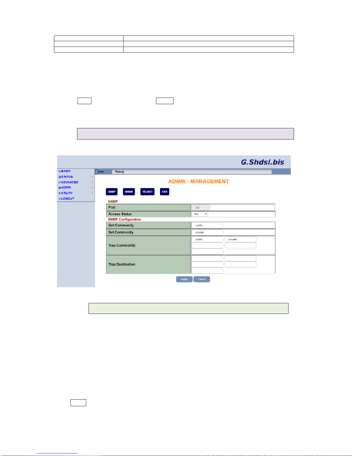
44..44..22..11
SSNNMMPP
Simple Network Management Protocol (SNMP) defines the exchange of messages between a
network management client and a network management agent for remote management of network
nodes. These mes sages contain reques ts to get and set variables that ex ist in net work nodes in
order to obtain statistics, set configuration parameters, and monitor network events. SNMP
communications can occur over LAN or WAN connection.
The router can generate SNMP traps to indicate alarm conditions, and it relies on SNMP
community strings to implement SNMP security. The SHDSL.bis routers support
SNMPv1/SNMPv2 (RFC 1157/1901/1905) and MIB-II (RFC 1213/1493)
Click SNMP to configure the parameters for remote management via SNMP.
Dynamix UM-S4FB Series rev.2 User Manual V0.06
39

SNMP
Item
Description
Port
Enter port number for the SNMP service
Access Status
Click on the drop-down list and select ALL to allow the service or Disable
WAN to disable the remote management serv ic e
SNMP Configuration
Item
Description
Get Community
Enter the password for the incoming Get and Get Next requests from the
management station. The default is public which allows all requests.
Set Community
Enter the password for the incoming Set requests from the management
station. The default is public which allows all requests .
Trap Community
Enter the password sent with each trap to the SNMP manager. The default
is public which allows all requests.
Trap Destination
Enter the IP address of the station to send SNMP traps
Click on Apply to save the parameters or Cancel to start configuring this page from beginning.
44..44..22..22
WWWWWW
Click WWW to configure the parameters for remote management via WWW
WWW
Item
Description
Port
Enter port number for remote management via WWW
Access Status
Click on the drop-down list and select ALL to allow the service or Disable
WAN to disable the remo te manageme nt serv ic e
44..44..22..33
TTEELLNNEETT
Click TELNET to configure the parameters for remote management via TELNET
Dynamix UM-S4FB Series rev.2 User Manual V0.06
40

TELNET
Item
Description
Port
Enter port number for remote management via TELNET
Access Status
Click on the drop-down list and select ALL to allow the service or Disable
WAN to disable the remote management servic e
Default: The TELNET allow accessible from LAN side only.
44..44..22..44
SSSSHH
Click SSH to configure the parameters for remote management via SSH
SSH
Item
Description
Port
Enter port number for remote management via SSH
Access Status
Click on the drop-down list and select ALL to allow the service or Disable
WAN to disable the remote management serv ic e
Default: The SSH allow accessible from LAN side only.
44..5
5
UUttiilliittyy
Overview
This section describes the utility of the SHDSL.bis router including:
SYSTEM LOG
Capturing log information
SYSTEM TOOL
Backup and restore configuration, and load the factory default
configuration
UPGRADE
Upgrade the firmware
Dynamix UM-S4FB Series rev.2 User Manual V0.06
41

RESTART
Restart the router.
44..55..1
1
SSYYSSTTEEMM LLOOGG
44..55..11..11
SSYYSSTTEEMM LLOOGG
UTILITY>SYSTEM LOG
SHDSL.bis routers s upport detailed logging inform ation via System Log function. The system log
protocol allows devices to send event notification messages across an IP network to syslog
servers that collect the event message. The router can generate a syslog message and send it to a
syslog server.
You may click Refresh to renew the Sytem Log page or Clear Log to delete all log information.
44..55..11..22
SSYYSSTTEEMM LLOOGG SSeerrvveerr SSeettttiinngg
SYSLOG Server Setting
Item
Description
Active
Activate the syslog server
Dynamix UM-S4FB Series rev.2 User Manual V0.06
42

Syslog IP Address
Enter IP address for syslog server
Log Facility
The log facility allows you to log the messages to different files in the syslog
server . R efer to the documentation of your syslog program for more details.
Priority
Assign priority to the traffic of the classifier
Order
Ordering number of the classifier
44..55..2
2
SSyysstteemm TTooooll
UTILITY>SYSTEM TOOL
System Tool provides three main functions: Backup Configuration, Restore Configuration and
Load Factory Default settings.
Click Backup to save config.cfg in your computer.
To res tore a previousl y saved conf ig file from your com puter. Click Browse to select th e file and
then click Upload.
Click Reset to load factory default settings to the router. A warning message will appear.
Confirm by clicking on OK.
44..55..3
3
UUppggrraaddee
UTILITY>UPGRADE
Dynamix UM-S4FB Series rev.2 User Manual V0.06
43

You can upgrade the SHDSL.bis router using the upgrade function.
Click Browse to select the firmware file and then click Upload. The system will reboot
automatically after finish the firmware upgrade operation.
44..55..4
4
RReessttaarrtt
UTILITY>RESTART
Use RESTART to reboot the SHDSL.bis router.
Click on Restart to reboot the system.
44..6
6
LLOOGGOOUUTT
Overview
To logout the router, click on LOGOUT. A warning message will appear. Confirm by clicking on OK.
Dynamix UM-S4FB Series rev.2 User Manual V0.06
44

Example
44..66..1
1
LLAANN--ttoo--LLAANN ccoonnnneeccttiioonn wwiitthh bbrriiddggee MMooddee
44..66..11..11
CCOO ssiiddee
Click Bridge and STU-C Side to setup Bridge mode of the Router
Enter LAN Parameters
IP: 192.168.0.1
Subnet Mask: 255.255.255.0
Gateway: 192.168.0.1
Enter WAN Parameters
VPI: 0
VCI: 32
Click LLC
Dynamix UM-S4FB Series rev.2 User Manual V0.06
45

Click Apply
The router will reboot with the new setting.
44..66..11..22
CCPPEE SSiiddee
Click Bridge and STU-C Side to setup Bridge mode of the Router
Enter LAN Parameters
IP: 192.168.0.2
Subnet Mask: 255.255.255.0
Gateway: 192.168.0.2
Enter WAN Parameters
VPI: 0
VCI: 32
Click LLC
Click Apply
The router will reboot with the new setting.
Dynamix UM-S4FB Series rev.2 User Manual V0.06
46

5
5
CCoonnffiigguurraattiioonn vviiaa SSeerriiaall CCoonnssoollee oorr TTeellnneett
In this section, the basic of console line configuration will be described on below.
55..1
1
IInnttrroodduuccttiioonn
55..11..1
1
SSeerriiaall CCoonnssoollee
Check the connectivit y of the RS-232 cable. Connect the male 9-pin end of console port of the
router and connect the female end to a serial port of your computer.
Start your terminal access program by VT100 terminal emulation with the following parameters:
Parameter
Value
Baudrate
115200bps
Data Bits
8
Parity Check
No
Stop Bits
1
Flow-control
No
Press the SPACE k ey until the login screen appe ars. When you see the login s creen, you can
logon to Router.
5242-0000-1220160511
Beta r400
Wed May 11 05:34:57 UTC 2016
=======================================================
Welcome to Shdsl.bis Router Configuration Tool
UserName : root
Password : ****
Note: Only SPACE key invoke the login prompt. Pressing other keys does not work.
Note: The factory default User and Password are “root” for both.
55..11..2
2
TTeellnneett
Make sure the correct Ethernet cable connected the LAN port of your computer to this Router. The
LAN LNK LED indicator on the f r ont panel sha ll l ig ht if a c orr ect cab le is used. Starting your Telnet
client with VT100 term inal em ulation and c onnect ing t o th e m anagem ent IP of R outer, wait for the
login prompt appears. Input User and Password after login screen pop up,
Dynamix UM-S4FB Series rev.2 User Manual V0.06
47

User: root
Password: ****
Note: The default IP address is 192.168.0.1.
55..2
2
MMaaiinn mmeennuu
When enter to pr ompt s creen, you can inp ut comm and ? to view the available to p level m enus of
each command set:
For example: type ? after the #, will display the current level of available command sets as below:
Dsl#?
config enter submenu system
status enter submenu status
show enter submenu information
utility enter submenu utility
reboot reboot system
quit logout
Dsl#
Top level Command set Description:
Command
Description
config
Config parameters of router by entering submenu:
network
advance
mgmt
exit
status
View the status of router.
show
Show the system and configuration of router.
utility
Upgrade software and backup and restore configuration.
reboot
Reset and boot system. After you have completed all necessary setting,
make sure to app ly the n ew configur ati on to NVRAM and rebo ot the s ystem,
otherwise, all of your changes will not take effect.
quit
Quit system.
Dynamix UM-S4FB Series rev.2 User Manual V0.06
48

55..3
3
KKeeyy CCLLII CCoommmmaanndd ttrreeee oovveerrvviieeww
Dynamix UM-S4FB Series rev.2 User Manual V0.06
49
 Loading...