


DYNAMIX UM-A4W
ADSL Router
4 Port 10/100 Mbps
Fast Ethernet Switch
User Manual

Contents
Chapter 1 : Introduction 7
1.1 Features 7
1.2 Scope 11
1.3 Audience 12
1.4 Document Structure 13
1.5 System Requirement 14
Chapter 2 : Getting To Know IEEE 802.1 1b Wireless ADSL Router 15
2.1 The IEEE 802.11b Wireless ADSL Router’s Back Panel 15
2.2 The IEEE 802.11b Wireless ADSL Router’s Front Panel 16
2.3 Connection Mechanism 17
Chapter 3. Administrator’s Computer Setting 19
3.1 Windows 98/ME 20
3.2 Windows 2000 22
3.3 Windows XP 24
Chapter 4. Device Administration 26
4.1 Login 26
4.2 Quick Setup 29
4.2.1 Quick Setup : Automatic Setting 30
4.2.2 Quick Setup : Manual Setup 33
4.3 Advanced Mode 38
4.3.1 Advanced Setup—Status 39
4.3.1.1 Status – Main Status 40
4.3.1.2 Status – PPP 42
4.3.1.3 Status – ADSL 44
4.3.2 Advanced Setup—Configuration 47
4.3.2.1 Configuration—WAN 48
4.3.2.2 Configuration—LAN 57
4.3.2.3 Configuration—PPP 60
4.3.2.4 Configuration—NAT 67
4.3.2.5 Configuration – Virtual Server 69
4.3.2.6 Configuration – Bridge Filtering 71
4.3.2.7 Configuration—DNS 73
4.3.2.8 Configuration – Wireless 75
4.3.2.9 Configuration – WLAN Security 77
IEEE 802.11b Wireless ADSL Router P 4

4.3.2.10 Conf iguration – User Password Configuration 79
4.3.2.11 Configuration – Save Setting/Reboot 80
4.3.3 Advanced Setup – Admin Privilege 81
4.3.3.1 Admin Privilege – WAN Status 82
4.3.3.2 Admin Privilege – ATM Status 83
4.3.3.3 Admin Privilege – ADSL Configuration 84
4.3.3.4 dmin Privilege – Route Table 85
4.3.3.5 Admin Privilege – Learned MAC Table 87
4.3.3.6 Admin Privilege – RIP Configuration 88
4.3.3.7 Admin Privilege – Misc Configuration 92
4.3.3.8 Admin Privilege – TCP Status 96
4.3.3.9 Admin Privilege – Admin Password Configuration 97
4.3.3.10 Admin Privil ege – Reset To Factory Default 98
4.3.3.11 Admin Privilege – Diagnostic Test 99
4.3.3.12 Admin Privilege – System Log 103
4.3.3.13 Admin Privil ege – Local Code Image Update 104
4.3.3.14 Admin Privil ege – Network Firmware Im age Update 105
4.3.3.15 Admin Privilege – Boot Code Image Update 106
4.3.3.16 Admin Privilege – Firewall 107
4.3.3.16.1. 1 Advanced Options – Protection Policy 108
4.3.3.16.1.2 Adva nced Options – Hacker Log 110
4.3.3.16.1.3 Advanced Options – Service Filtering 111
4.3.3.16.2.1 Firewall Databases – IP Group 112
4.3.3.16.2.2 Fir ew all D atab ase s – Service G rou p 113
4.3.3.16.2. 3 Fire w al l Da taba se s – Time Window 114
4.3.3.16.3.1 Inbound/Outbound Policies – Inbound Policy 115
4.3.3.16.3.2 Inbound/Outbound Policies – Outbound Policy 119
4.3.4 Advanced Modep – Manage Public Servers 126
4.4 Status 128
4.4.1 Status – Current Setting 128
4.4.2 Status – System Log 129
IEEE 802.11b Wireless ADSL Router P 5

Appendix A : Network Address Translation 131
A.1 Basic NAT 132
A.2 Static NAPT 133
A.3 Functional Descriptions 134
A.3.1 Outbound Access 135
A.3.2 Inbound Access 137
Appendix B Frequently Asked Questions 138
Appendix C Troubleshooting Guide 141
Appendix D Network Setup Guide 142
Appendix E Common Error Messages 145
Appendix F Glossary 146
IEEE 802.11b Wireless ADSL Router P 6

Congratulations on your purchase of this outstanding IEEE 802.11b Wireless ADSL Router.
Dynamix UMA4W is an IEEE 802.11b Wireless and 4 Port Switch built-in ADSL Router that
allows ADSL connectivity while providing Wireless LAN capabilities for residential, industries
and SOHO environments. Wireless-B or the so-called 11b is the upcoming 11Mbps wireless
networking standard that’s widely deployed found in homes, businesses, and public wireless
hotspots around the world.
Dynamix UMA4W allows ADSL connectivity while providing Wireless LAN capabilities for
home or office users. It provides a downstream rate of up to 8Mbps and upstream rate of up to
1Mbps for ADSL connection and 11Mbps transfer data rate for the 11b connection.
With minimum setup, you can install and use the router within minutes.

ATM Protocols
Support PPPoA ( RFC2364 ).
Support PPPoE ( RFC2516 ).
Router/Bridged Ethernet over ATM ( RFC1483 ).
Classical IP over ATM ( RFC1577 ).
ATM Forum UNI 3.1/4.0 PVC, ATM SAR, ATM AAL5 and OFM F4/F5.
Support up to 8PVCs.
802.11b Wireless Networking
IEEE 802.11b standard compliant.
DSSS modulation with data rate up to 11Mbps.
Support 2.412GHz ~ 2.484GHz frequency ranges.
64-bit and 128-bit WEP encryption security.
Wireless access can be restricted by MAC address.
Wireless network name broadcast can be turned off so that only devices that have
the net
work name (SSID) can connect.
Built-in dual dipole diversity antenna.
Router Mode
IP Routing – RIPv1 and RIPv2.
Static Routing.
DHCP Server and Client.
Support DNS proxy.
Support NAT and NAPT functionality.
Support IPSec, L2TP, PPTP Pass-Through.
Support ICMP and IGMP.
Firewall
Statefull Packet Inspection ( SPI ).
DoS ( Denial of Service ) protection.
Service Filtering.
Access Policies based on IP Address, Service Group, Time, Inbound/Outbound Policy.
Hacker Log.
Ethernet Standards
Built-in 4 Port 10/100Mbps Ethernet Switch which compliant with IEEE 802.3x
standards
Automatic MDI/MDI-X crossover for 10/100Base-T/port.
Web-Based Management
Firmware upgrade via FTP.
WAN and LAN connection statistics.
Configuration of static routes and routing table, NAT/NAPT and VCs.
PPP user ID and password.
IEEE 802.11b Wireless ADSL Router P 8

Security Support
Hidden by NAT. NAT opens a temporary path to the Internet for requests originating
from the
local network. Requests origin ating from outside the LAN are d isc arded,
preventing use rs
LAN.
Port Forwarding with NAT. The IEEE 802.11b Wireless ADSL Router allows
you to direct incoming traffic to specific PCs based on the service port number of
the incoming request, or to one designated “DMZ” host computer. Forwarding of
single ports or ranges of ports are configurable.
Support URL Blocking. Prevent any LAN clients from accessing specific Internet site
by set-
ting the URL keywords. The IEEE 802.11b Wireless ADSL Router will reject
all those web site whose URL names are matched or partially matched with the
keywords.
Support MAC Fil t ering function. This function ena ble the adminis trator to control
LAN client
the
Content Filtering
Blocks unwanted traffic from the Internet to your LAN.
Blocks access from your LAN to Internet locations or services that you’d specified.
Logs security incidents. The IEEE 802.11b Wireless ADSL Router will log
security events such as blocked
administrator logins.
Extensive Protocol Support
IP Address Sharing by NAT. The IEEE 802.11b Wireless ADSL Router allows several
networked PCs to share an
may be statically or dynamically
Automatic Configuration of DHCP. The IEEE 802.11b Wireless ADSL Router
dynamically assigns network configuration information, including IP Address, WAN
Gateway, Domain Name Server ( DNS ) Addresses, … etc. This greatly simplifies
configuration of PCs on your local network.
Dynamic DNS. This is a method of keeping a domain name linked to a changing IP
Address as not all computers use Static IP addresses. Typically, when a user connects
to the Internet,
and this address
PPP over Ethernet (PPPoE). PPPoE is a method for the encapsulation of PPP packets
over
Ethernet frames from the user to the ISP over the Internet. One reason PPPoE is
preferred
addition to data transport. A PPPoE session can be initiated by either a client
application residing on a PC, or by client firmware residing on a modem or router.
PPTP (Point-to-Point Tunneling Protocol) – PPTP is a protocol ( set of communication
rules )
that allows c or porations to ex t en d their own corp or at e n et work through p riv ate
" Tunnels "
network as a single large
own lines for wide-area com
kind of interconnection is known as a virtual private network.
out-side the LAN from finding and directly accessing the PCs on the
computers to access the Internet by the hardware MAC Address.
incoming traffic, port scans, attacks, and
Internet account using only a single IP address, which
assigned by your Internet service provider (ISP).
the user's ISP assigns an unused IP address from a po ol of IP addresses,
is used only for the duration of that specific connection.
by ISPs is because it provides authentication (username and password) in
over the public Internet. Effectively, a corporation uses a wide-area
local area network. A company no longer needs to lease its
munication but can securely use the public networks. This
IEEE 802.11b Wireless ADSL Router P 9

Easy Installation and Management
Quick Setup. The Quick Setup is meant to help you install the product quickly and
easily.
Browser-based man agement. Browser-b ase d configuration all ows you to easily
configure
Macintosh or
your router from almost any type of personal computer, such as Windows,
Linux.
Visual monitoring. The IEEE 802.11b Wireless ADSL Router’s front panel’s LEDs
provide an easy way to monitor the connection status and activity.
IEEE 802.11b Wireless ADSL Router P 10

1.5 System Requirement
Personal computer (PC)
Pentium II compatible processor and above
Internet Browser
64 MB RAM or more
50 MB of free disk space minimum
Ethernet Network Interface Controller (NIC) RJ45 Port
An installed IEEE 802.11b or IEEE 802.11g wireless Adaptor
Ethernet (CAT5) Cable
Power adaptor for IEEE 802.11b Wireless ADSL Router
CD-ROM drive
IEEE 802.11b Wireless ADSL Router P 14

Chapter 2 : Getting To Know Wireless ADSL Router
2.1 Back Panel :
The back panel of the IEEE 802.11b Wireless ADSL Router contains WAN/LAN Connection,
USB Port Connection and Power Switch.
WAN
Ports 1-4
USB
Power
Switch
Port for connecting the IEEE 802.11b Wireless ADSL Router to the
ADSL Service Provider.
Four 10/100Mbps Ethernet Port for connecting the IEEE 802.11b
Wireless ADSL Router to the network devices, such as PCs.
USB Rev. 1.1 specification compliant for host computer connection.
12VDC/1A Power adapter outlet.
Power Switch to ON/OFF the IEEE 802.11b Wireless ADSL Router.
IEEE 802.11b Wireless ADSL Router P 15
!
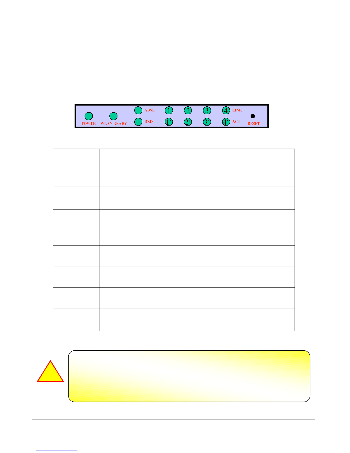
2.2 Front Panel
The IEEE 802.11b Wireless ADSL Router’s LEDs indicators display information about the
device’s status.
POWER
WLAN
READY
ADSL
RXD
1 : LINK/ACT
2 : LINK/ACT
3 : LINK/ACT
Steady green light indicates the router is powered on.
Wireless system status indicators when blinking indicate wireless
system is alive.
Steady green light indicates a valid ADSL connection. This will light
after the ADSL negotiation process has been settled.
Blinking green light indicates an active WAN session.
Steady green light indicates a valid Ethernet connection. Blinking
green light indicates active Ethernet session.
Steady green light indicates a valid Ethernet connection. Blinking
green light indicates active Ethernet session.
Steady green light indicates a valid Ethernet connection. Blinking
green light indicates active Ethernet session.
4 : LINK/ACT
RESET
The Reset button can be used in one of two ways :
1. Reboot the IEEE 802.11b Wireless ADSL Router while keeping all of its setting.
2. Restore the IEEE 802.11b Wireless ADSL Router’s factory defaults and clear
Steady green light indicates a valid Ethernet connection. Blinking
green light indicates active Ethernet session.
Restore the IEEE 802.11b Wireless ADSL Router’s factory default
setting.
all the setting.
IEEE 802.11b Wireless ADSL Router P 16

!
A
2.3 Connection Mechanism
This section describes the hardware connection mechanism of your IEEE 802.11b Wireless ADSL
Router on your Local Area Network (LAN) connect to the Internet, how to configure IEEE
802.11b Wireless ADSL Router for Internet access or how to manually configure your Internet
connection.
You need to prepare the following items before you can establish an Internet connection through
your IEEE 802.11b Wireless ADSL Router :
1. A computer which must have an installed Ethernet Adaptor and an Ethernet Cable or
2. A computer which have an installed IEEE 802.11b or IEEE 802.11g Wireless Adaptor.
3. An ADSL service account and configuration information provided by your Internet Service
Provider ( ISP ). You will need one or more of the following configuration parameters to
connect your IEEE 802.11b Wireless ADSL Router to the Internet :
a. VPI/VCI parameters
b. Multiplexing Method
c. Host and Domain Names
d. ISP Login Name and Password
e. ISP Domain Name Server ( DNS ) Address
f. Fixed or Static IP Address.
Figure below shows the overall hardware connection mechanism of your IEEE 802.11b Wireless
ADSL Router.
ll the Ethernet port of the IEEE 802.11b Wireless ADSL Router supports auto
crossover capability.
IEEE 802.11b Wireless ADSL Router P 17

A
!
Follow the following steps or instructions for connecting your IEEE 802.11b Wireless ADSL
Router :
1. Turn off your computer.
2. Connect the ADSL port of your IEEE 802.11b Wireless ADSL Router to the splitter DS L port
with a RJ-11 cable.
3. Connect the Ethernet cable ( RJ-45 ) from your IEEE 802.11b Wireless ADSL Router to the
Ethernet Adaptor in your computer.
4. Connect the Power adaptor to the IEEE 802.11b Wireless ADSL Router and plug the other
end into a Power outlet.
5. Turn on your IEEE 802.11b Wireless ADSL Router.
The Power light will lit after turning on the IEEE 802.11b Wireless ADSL Router.
uto and self diagnostic process will turn the LED indicators ON and OFF during
the process.
6. Turn on your computer.
7. Refer to the next chapter to setup or configure your Network Adaptor.
IEEE 802.11b Wireless ADSL Router P 18

Chapter 3. Administrator’s Computer Setting
The instruction in this section will help you configure your computers to be able to communicate with
this IEEE 802.11b Wireless ADSL Router.
Computers access the Internet using a protocol called TCP/IP (Transmission Control Protocol/ Internet
Protocol). Each computer on your network must have TCP/IP installed and selected as its networking
protocol. If a Network Interface Card (NIC) is already installed in your PC, then TCP/IP is probably
already installed as well.
The following description assumes the IEEE 802.11b Wireless ADSL Router been set to factory default.
(If not, please hold the reset button down for 10 seconds). The default IEEE 802.11b Wireless ADSL
Router’s LAN IP is 10.0.0.2.
Follow the procedures below to set your computer function as a DHCP Client.
IEEE 802.11b Wireless ADSL Router P 19

3.1 Windows 98/ME
Step 1: Click Start→Settings→Control Panel.
Step 3: Select the network adapter
installed and click on Properties.
1
2
Step 2: Double-click the Network icon.
Step 4: Select Obtain an IP address automatically.
IEEE 802.11b Wireless ADSL Router P 20

1
2
Step 5: Erase all the previous setting.
Step 7: System may request to restart the Windows operating system. Press Yes to restart your computer.
Step 6: Select Disable DNS then click OK.
IEEE 802.11b Wireless ADSL Router P 21

3.2 Windows 2000
Step 1: Click Start→Settings→Control Panel.
Step 3: Right Click on the Local Area
Connection and select Properties.
Step 2: Double-click the Network and Dial-up
Connections icon.
Step 4: Select Internet Protocol(TCP/IP) and
click Properties.
IEEE 802.11b Wireless ADSL Router P 22

1
Step5: Select Obtain an IP address automatically
and Obtain DNS server address
automatically . Then click OK.
3
2
IEEE 802.11b Wireless ADSL Router P 23

3.3 Windows XP
Click Switch to Classic View.
Step 1: Click Start→Click Control Panel.
Step 3: Right Click on the Local Area
Connection and select Properties.
Step 2: Double-click the Network Connections icon.
Step 4: Select Internet Protocol(TCP/IP)
and click Properties.
IEEE 802.11b Wireless ADSL Router P 24

1
2
Step5: Select Obtain an IP address automatically and
Obtain DNS server address automatically. Then
click OK.
3
IEEE 802.11b Wireless ADSL Router P 25

Chapter 4. Device Administration
For your convenience, an Administrative Utility has been programmed into the IEEE 802.11b Wireless
ADSL Router. This chapter will explain all the functions in this utility. All IEEE 802.11b Wireless
ADSL Router based administrative tasks are performed through this web utility.
4.1 Login
Levels of Access : There are two levels of access rights/privileges for the IEEE 802.11b Wireless
ADSL Router:
Administrator : User name admin, the administrator account has complete read/write access
on all pages (Status, Configuration, Admin Privilege, and Firewall Configuration). Admin
account also has FTP server access.
User : User name user, the User account has read/write access to pages under the Status and
Configuration sections.
The following steps will enable you to log into the IEEE 802.11b Wireless ADSL Router.
1. Launch the Web browser (Internet Explorer, Netscape, etc.).
2. Enter the LAN port default IP address (default gateway) http://10.0.0.2
3. Entry of the username and password will be prompted. Enter the default login User Name and
Password :
The default login User Name of the administrator is “admin”, and the default login Password
is “epicrouter”.
The default login User Name for the non-administrator is “user”, and the default login
Password is “password”.
in the address bar.
IEEE 802.11b Wireless ADSL Router P 26

4. Remember my password check box : By default, this box is not checked. Users can check this box
so that Internet Explorer will remember the User name and Password for future logins. It is
recommended to leave this box unchecked for security purposes.
“Admin” and “User” passwords can be changed after login. Refer to Section 4.3.2.8 for User
Password configuration and Section 4.3.3.9 for Admin Password configuration for further instruction.
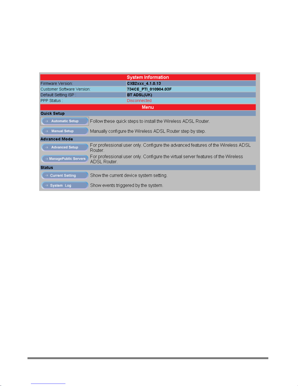
Upon entering the address into the web browser, the configurable main page with all the device status
information will pop up as shown in Figure below :
IEEE 802.11b Wireless ADSL Router P 27

1. System Information : Show the current IEEE 802.11b Wireless ADSL Router
Firmware version, Customer Software version, Current ISP setting and PPP Status
2. Menu : Describe the way to Setup/Configuration your IEEE 802.11b Wireless
ADSL Router.
A. Quick Setup : The Quick Setup is meant to help you install the IEEE 802.11b
Wireless ADSL Router Quickly and easily.
i. Automatic Setup : Automatic Setup by selecting country and ISP from
the list step by step.
ii. Manual Setup : Entering all the setting/configuration manually. Check
your ISP for the setting details.
B. Advanced Mode :
installation
/configurations for advance user. No changes should be ma de
to this section without a
The Advanc e d M ode de s cribe the detail instruction on
thorough understanding of networking concepts.
i. Advanced Setup : For professional user ONLY. No changes should be
made to this section without a thorough understanding of networking
concepts.
ii. Manage Public Server : For professional user ONLY. No changes should
be made to this section without a thorough understanding of networking
concepts.
C. Status :
previous connection, setting and con
provided under the Status tab are read only and can be
Display the IEEE 802.11b Wireless ADSL Router’s current or
figuration status. All the information
changed upon
setting/configuration of the IEEE 802.11b Wireless ADSL Router.
i. Current Setting : Shows the current setting/configuration status.
ii. System Log : Shows the System connection information.
IEEE 802.11b Wireless ADSL Router P 28
4.2 Quick Setup
The Quick Setup is meant to help you install the IEEE 802.11b Wireless ADSL Router quickly and
easily. Click “Automatic Setup” and follow the steps describe below to complete your installation.
IEEE 802.11b Wireless ADSL Router P 29

4.2.1 Quick Setup : Automatic Setting
1. Automatic Setup :
STEP 1. Select the presetting country form the list.
For 1483 Bridged LLC encapsulation, there are two available IP mode :
i. Bridge Mode : Click “Enable” or “Disable” for the connection mode.
Check your ISP for the connection/setting details.
ii. IP Mode : Click “Dynamic IP” or “Static IP” for the connection mode.
Check your ISP for the connection/setting details.
If “Static IP” mode is chosen, more terms need to be filled before any
Internet access is available. Check your ISP for the setting/configuration
details.
IEEE 802.11b Wireless ADSL Router P 30

For PPPoA VC-Mux and PPPoE LLC encapsulation :
Manually enter your “Service Name”, “User Name” and “Password” which will be
provided by your ISP. Check your ISP for the details.
IEEE 802.11b Wireless ADSL Router P 31

STEP 2.
Click “Save Setting” after your choice.
The IEEE 802.11b Wireless ADSL Router system will reboot and activate your setting. Click
“Back To Home” after the reboot process. Connection to the Internet is available after the above
process.
IEEE 802.11b Wireless ADSL Router P 32

4.2.2 Quick Setup : Manual Setup
“Manual Setup” allows you to manually configure the IEEE 802.11b Wireless ADSL Router step by
step by selecting User Configured in the field. Click “Manual Setup” and follow the installation
wizard to complete the installation process.
Manually enter the “Encapsulation” type, “VPI” and “VCI” setting. Check your ISP for the
setting/configuration details. These modes are guidelines for setting up the WAN interface. Table
below lists the example of the mode configurations.
IEEE 802.11b Wireless ADSL Router P 33

A. Bridge Mode: Bridge Mode is used when there is one PC connected to the LAN-side
Ethernet port. IEEE 802.1D method of transport bridging is used to bridge between the WAN
(ADSL) side and the LAN (Ethernet) side, i.e., to store and forward. There are two
encapsulation type for Bridge Mode :
i. 1483 Bridged IP LLC : If 1483 Bridged IP LLC mode is selected, select
“Enable” or “Disable” to activate the WAN configuration setting. Select
“Dynamic IP”, which will automatically assigned by your ISP or “Static
IP”, which will be provided by your ISP.
ii. 1483 Bridged IP VC-Mux : If 1483 Bridged IP VC-Mux mode is
selected, select “Enable” or “Disable” to activate the WAN
configuration setting. Select “Dynamic IP”, which will automatically
assigned by your ISP or “Static IP”,
which will be provided by your ISP.
iii. 1483 Routed IP LLC : If 1483 Router IP LLC mode is selected, select
“Enable” or “Disable” to activate the WAN configuration setting. Select
“Dynamic IP”, which will automatically assigned by your ISP or “Static
IP”, which will be provided by your ISP.
iv. 1483 Routed IP VC-Mux : If 1483 Routed IP VC-Mux mode is selected,
select “Enable” or “Disable” to activate the WAN configuration setting.
Select “Dynamic IP”, which will automatically assigned by your ISP or
“Static IP”, which will be provided by your ISP.
IEEE 802.11b Wireless ADSL Router P 34

For “Dynamic IP”, nothing have to fill in, just click “Save Setting” to activate your configuration.
For “Static IP”, please check with your ISP to fill in the necessary setting before clicking “ Save
Setting” to activate your configuration.
“Set IP” : Static IP Settings are for users who have a Static IP Address (WAN side) from
their ISP.
“Static IP Address” : This is the static IP Address given by the ISP.
Range for IP Address is x.x.x.y, where 0
≦ x≦
255 and 1 ≦ y≦ 254, default is
192.168.241.101.
“Subnet Mask” : This is the subnet mask given by the ISP.
Range for Subnet Mask is x.x.x.x, where 0
≦
x ≦ 255, default is 255.255.255.0
“Gateway” : This is the Gateway given by the ISP.
Range for Gateway is x.x.x.y, where 0
≦ x≦
255 and 1 ≦ y≦ 254, default is
0.0.0.0.
IEEE 802.11b Wireless ADSL Router P 35

“DNS Proxy” : The DNS proxy on the IEEE 802.11b Wireless ADSL Router records the
available DNS servers and forwards DNS query messages to one of DNS servers.
“DNS Proxy Enable/Disable” : When the DNS Proxy is Disabled, the
LAN port does not process the DNS query message. For the DHCP
requests from local PCs, the DHCP server will set the user-configured
DNS server as the DNS server. Then all DNS query messages will be
directly sent to the DNS servers. DNS Proxy is enabled by default.
“Auto Discovered Enable/Disable” : When enabled (default), the DNS
proxy will store the DNS server IP addresses obtained from DHCP client
or PPP into the table. All DNS query messages will be sent to the
dynamically obtained DNS server. Select this option when the DNS
Server address is unknown but provided (automatically) by the ISP.
“User Configured Enable/Disable” : When enabled, the DNS proxy
will use the user-configured DNS server. All DNS query messages will
be sent to the DNS server. Enter the DNS IP in the DNS Server field.
Select this option when the DNS Server address assigned by the ISP is
known. User Configured is disabled by default.
“DNS Server” : This is the user defined DNS server URL name and IP. Default is
“Disable”.
“URL Name Add/Delete” : This is the URL name for the DNS server.
This can be up to 255 characters.
“Host IP (Add Only)” : This is the IP address of the DNS Server.
“Save Setting” : Clicking this will link the user to the “Save Settings” page.
B. Router Mode : Router Mode is used when there is more than one PC connected to the
LAN-side Ethernet port. This enables the ADSL WAN access to be shared with multiple
nodes on the LAN. Network Address Translation (NAT) is supported so that one WAN-side
IP address can be shared among multiple LAN-side devices. DHCP is used to serve each
LAN-side device and IP address. There are four encapsulation type for Router Mode :
i. PPPoA VC-Mux : If PPPoA VC-Mux mode is selected, manually enter
your “User Name”, “Input Password” and “Confirm Password” then
click “Save Setting” after your configuration. Check with your ISP for
the VPI/VCI setting details.
ii. PPPoA LLC : If PPPoA LLC mode is selected, manually enter your
“User Name”, “Input Password” and “Confirm Password” then click
“Save Setting” after your configuration. Check with your ISP for the
VPI/VCI setting details.
IEEE 802.11b Wireless ADSL Router P 36

iii. PPPoE VC-Mux : If PPPoE VC-Mux mode is selected, manually enter
your “User Name”, “Input Password” and “Confirm Password” then
click “Save Setting” after your configuration. Check with your ISP for
the VPI/VCI setting details.
iv. PPPoE LLC : If PPPoE LLC mode is selected, manually enter your
“User Name”, “Input Password” and “Confirm Password” then click
“Save Setting” after your configuration. Check with your ISP for the
VPI/VCI setting details.
PPP Half Bridge: Although the Router mode is capable of terminating the PPP in the
modem and hence does not require PPPoE client software on the host PC, there are some
disadvantages to Router mode when only single-user support is required. For instance, Router
mode uses NAT which requires ALG support. PPP Half Bridge also terminates the PPP in the
modem and does not require a PPPoE client on the PC. However, PPP Half Bridge does not
use NAT and is not limited by ALGs. PPP Half Bridge will work with Ethernet interface to
the PC.
Single-User Mode: Only one computer is connected at the LAN side through Ethernet.
Multi-User Mode: Multiple computers are connected at the LAN side through Ethernet.
IEEE 802.11b Wireless ADSL Router P 37

4.3 Advanced Mode
The Advanced Mode describe the detail instruction on installation/configurations for advance user.
Click “Advanced Setup” icon to login the configuration/setting pages.
IEEE 802.11b Wireless ADSL Router P 38

4.3.1 Advanced Setup—Status
Click “Advanced Setup”, the device “Home Page” or “Main Status” window will pop up. It shows
all the current setting/configuration information of the IEEE 802.11b Wireless ADSL Router.
IEEE 802.11b Wireless ADSL Router P 39

4.3.1.1 Status – Main Status
The links under the Main Status column are associated with the pages that represent the status of
system
(computer and IEEE 802.11b Wireless ADSL Router) and interfaces (Connections). This
includes
LAN, WAN and ADSL status. These pages can be viewed and modified by both user and
admin accounts.
System Info
Firmware Version
Shows the firmware version you are using. Future firmwar
e
version of this IEEE 802.11b Wireless ADSL Router will b
e
posted
and
available
for
download
on
website
at www.godynamix.com.
Customer
Software
Version
Shows the software control code
WAN
IP Address
Shows the IEEE 802.11b Wireless ADSL Router’s IP Address.
The
default value is 10.0.0.2.
Subnet Mask
Shows the Subnet Mask of the WAN (ADSL) Interface
MAC Address
Shows the WAN MAC Address of the WAN (ADSL) Interface.
IEEE 802.11b Wireless ADSL Router P 40

LAN
IP Address
Shows the IEEE 802.11b Wireless ADSL Router’s IP Address.
The default value is 10.0.0.2.
Subnet Mask
Shows the Subnet Mask of the LAN Interface
MAC Address
Shows the WAN MAC Address of the LAN Interface.
LAN
Index
Shows the number of Ethernet device connected to the IEEE
802.11 b W ireless ADSL Router.
IP Address
Shows the IEEE 802.11b Wireless ADSL Router’s IP Address.
The default value is 10.0.0.2.
MAC Address
Shows the WAN MAC Address of the LAN Interface.
IEEE 802.11b Wireless ADSL Router
P 41

4.3.1.2 Status – PPP
The PPP Status page shows the status of each PPP session for each PPP interface. This page contains
information that is dynamic and will refresh every 8 seconds.
Note: PPP interfaces can be created, modified, and deleted in the PPP Configuration page.
PPP (Point-to-Point Protocol): The table displays the following fields:
Connection Name: This is user defined. User defined connections for PPP can be created in
PPP Configuration page.
Interface: States the interface that is being used (PVC0 ... PVC7).
Mode: There are two available modes for the connection:
PPP over Ethernet (PPPoE)
PPP over ATM (PPPoA)
Status: States whether PPP connection is Connected or Not Connected.
Packets Sent: Number of packets sent by a particular PPP Connection.
Packets Received: Number of packets received by a particular PPP Connection.
Bytes Sent: Number of bytes sent by a particular PPP Connection.
Bytes Received: Number bytes received by a particular PPP Connection.
Connect and Disconnect: This field allows you to manually connect/disconnect the PPP
connection for each PPP interface. In other words, each PPP session can be connected and
disconnected individually.
Connection #: Specifies the PPP session to be connected/disconnected.
Connect/Disconnect Execute: Press this button to either connect or disconnect. Connection
status dialog will be displayed below the Execute button after it is pressed. Sample dialog
with explanation:
IEEE 802.11b Wireless ADSL Router P 42

PPP X: Connecting... This is displayed while the PPP session is attempting to
connect to the ISP.
PPP X: Connect ERROR This is displayed when a connection cannot be made
due to an error.
PPP X: is currently not connected This is displayed when a disconnect attempt is
made on a session that is not currently connected.
PPP X: does not exist! This is displayed when a connect or disconnect attempt is
made on a session number that does not exist.
Click “Check the WAN configuration” will show you all the detail WAN setting/configuration of
this IEEE 802.11b Wireless ADSL Router. Refer to Section 4.3.2 for details.
IEEE 802.11b Wireless ADSL Router P 43

4.3.1.3 Status – ADSL
The ADSL Status page shows the ADSL physical layer or link status. The information displayed on
this page is either inherent to the IEEE 802.11b Wireless ADSL Router or set by the ADSL Central
Office (CO) DSLAM, neither of which cannot be changed by the user. This page contains information
that is dynamic and will refresh every 2 seconds.
Showtime Firmware Version: This field displays the ADSL data pump firmware version
number.
Line State: This field displays the ADSL connection process and status. The different states
for this field are as follows:
Activation: The IEEE 802.11b Wireless ADSL Router is in this state when it is
attempting to start the activation process.
Initialization: The IEEE 802.11b Wireless ADSL Router is initializing handshake
with the CO.
Training: This is a part of the handshake process with the CO.
Channel Analysis: This is a part of the handshake process with the CO.
Exchange: This is a part of the handshake process with the CO.
Down: This indicates that the ADSL connection is down.
Showtime: This indicates that a connection has been established between the IEEE
802.11b Wireless ADSL Router and the CO.
IEEE 802.11b Wireless ADSL Router P 44

Modulation: This field displays the ADSL modulation status, which can either be G.dmt or
T1.413.
Annex Mode: This field displays the ADSL annex mode, which can either be Annex A or
Annex B.
Startup Attempts: This field displays the number of ADSL connection attempts after loss of
showtime. A connection attempt is recorded only if showtime is attained.
Max TX Power: This field displays the transmit output power level of the CPE (Customer
Premise Equipment), which is the transmit output power level of the IEEE 802.11b Wireless
ADSL Router.
CO Vendor: This field displays the Central Office (CO) DSLAM vendor name, if available.
If the IEEE 802.11b Wireless ADSL Router is not connected to an ADSL vendor, then
“UNUSED_VENDOR_0” will appear in this field.
Elapsed Time: This field displays the time of the IEEE 802.11b Wireless ADSL Router has
been in operation.
This is the amount of time the IEEE 802.11b Wireless ADSL Router is on, not the amount of
time it is connected to the PC or in ADSL status.
SNR Margin: Signal to Noise Ratio (SNR) is the measure of signal intensity relative to the
background noise. The SNR Margin is the amount of increased noise that can be tolerated
while maintaining the designated BER (bit error rate). The SNR Margin is set by Central
Office DSLAM. If the SNR Margin is increased, bit error rate performance will improve, but
the data rate will decrease. Conversely, if the SNR Margin is decreased, bit error rate
performance will decrease, but the data rate will increase.
Line Attenuation: Attenuation is the decrease in magnitude of the ADSL line signal between
the transmitter (Central Office DSLAM) and the receiver (Client IEEE 802.11b Wireless
ADSL Router), measured in dB. It is measured by calculating the difference in dB between
the signal power level received at the Client IEEE 802.11b Wireless ADSL Router and the
reference signal power level transmitted from the Central Office DSLAM.
Errored Seconds: During Showtime, if any given second contains a CRC error, then that
second will be declared and recorded as an Errored Second.
Loss of Signal: Loss of signal refers to the IEEE 802.11b Wireless ADSL Router losing an
ADSL signal, not the computer losing a signal with the modem. Loss of Signal event is only
recorded if the signal is lost while the IEEE 802.11b Wireless ADSL Router is in showtime
status. This field displays the count of ADSL signal loss events.
Loss of Frame: A frame is a unit of data in ATM. This field displays the count of ADSL
frame loss events. A Loss of Frame event is only recorded if the signal is lost while the IEEE
802.11b Wireless ADSL Router is in showtime status.
IEEE 802.11b Wireless ADSL Router P 45

CRC Errors: Cyclic Redundancy Check (CRC) is a method for checking errors in data
transmissions. This field displays the number of transmit data frames containing CRC errors.
Data Rate: This field displays the ADSL data rate in kbps.
Latency: Latency, synonymously delay, is the amount of time it takes for a packet of data to
get from one designated point to another. This field displays the two mapping modes for
latency (fast and interleaved).
IEEE 802.11b Wireless ADSL Router P 46

4.3.2 Advanced Setup — Configuration
The links under Configuration column are associated to the pages that represent the configurations of
system and interfaces. These pages can be viewed and modified by both user and admin accounts.
Note: When any settings are changed, please go to the Save Settings page to save the new setting(s)
and reboot the IEEE 802.11b Wireless ADSL Router. Changes will not take effect until the settings
are saved and the IEEE 802.11b Wireless ADSL Router is rebooted. If power is lost before saving,
all new configurations since the last save will be lost, even if they were submitted.
IEEE 802.11b Wireless ADSL Router P 47

4.3.2.1 Configuration—WAN
The WAN configuration page allows you to set the configuration for the WAN/ADSL ports. Before
you enter the WAN Configuration page, you will be asked to select an adapter (PVC0 through PVC7)
first.
Once you select the adaptor, then following page will appear.
IEEE 802.11b Wireless ADSL Router P 48

A. Change Adapter : Click the “Change Adapter” tab to select the PVC Setting. Click “Submit after
your choice to view the setting/configurations details.
B. Main Setting :
Virtual Circuit: Select Enable to activate the current PVC configuration. The current PVC is
displayed at the top of the page in parenthesis. Default is Enabled for PVC0 and Disabled for
PVC1-PVC7.
VPI: Virtual Path Identifier is a virtual path used for cell routing that is identified by an eight
bit field in the ATM cell header. The VPI field specifies this eight bit identifier for routing.
Range for VPI field is 0-255, default is 0.
VCI: A Virtual Channel Identifier is a virtual channel that is identified by a unique numerical
tag that is defined by a 16-bit field in the ATM cell header. The purpose of the virtual
channel is to identify where the cell should travel. The VCI field specifies this 16 bit
numerical tag that determines the destination.
Range for VCI field is 0-65535, default is 35.
C. Static IP Settings :
Static IP Settings are for users who have a Static IP Address (WAN side) from their ISP.
IP Address: This is the static IP Address given by the ISP.
Range for IP Address is x.x.x.y, where 0
≦ x≦
192.168.241.101.
Subnet Mask: This is the subnet mask given by the ISP.
Range for Subnet Mask is x.x.x.x, where 0
≦ x≦
Gateway: This is the Gateway given by the ISP.
Range for Gateway is x.x.x.y, where 0
≦ x≦
255 and 1 ≦ y≦ 254, default is 0.0.0.0.
D. Encapsulation :
The different types of encapsulation include :
i. PPPoA VC-Mux
ii. PPPoA LLC
iii. 1483 Bridged IP LLC
iv. 1483 Routed IP LLC
v. 1483 Bridged IP VC-Mux
vi. 1483 Routed IP VC-Mux
vii. Classical IP over ATM
viii. PPPoE VC-Mux
ix. PPPoE LLC
x. PPPoE None.
255 and 1 ≦ y≦ 254, default is
255, default is 255.255.255.0
IEEE 802.11b Wireless ADSL Router P 49

E. DHCP Client :
DHCP Client: This is to enable or disable (default) the IEEE 802.11b Wireless ADSL Router
WAN as a DHCP client, where the ISP would be the DHCP server. DHCP Client is generally
used in the following encapsulations: 1483 Bridged IP LLC, 1483 Routed IP LLC, 1483
Bridged IP VC-MUX, 1483 Routed IP VC-Mux, and Classical IP over ATM. This option is
for non-static (dynamic) IP addresses.
Host Name: When DHCP Client is Enabled, copy the ISP recognized Host Name here. The
Host Name can be up to 19 characters.
IEEE 802.11b Wireless ADSL Router P 50

F. PPP “Advanced PPP Configuration” :
The PPP “Advanced PPP Configuration” allows you to configure multiple PPP sessions for
each PVC. Multiple PPP sessions enables you to set up different connection settings and be able to
toggle/choose those settings for each PVC. The IEEE 802.11b Wireless ADSL Router can support
up to total of 16 PPP sessions, and each PVC can support up to 8 PPP sessions. The multiple PPP
sessions may be configured with any combination over 8 PVCs.
Service Name: The Service Name of the PPP session is required by some ISPs. If the ISP
does not provide the Service Name, please leave it blank.
User Name: Enter the PPP user name (provided by the ISP). The User Name can be up to 127
characters.
Note: You cannot have two different user accounts with the same account name. If a
different User Name with an already existing Account ID is submitted, it will replace the
previous account with that Account ID. You can have the same User Name and
Password for two different accounts (Account ID).
Password: Enter the PPP password (provided by the ISP). The Password is not needed to
delete or modify the account. The Password can be up to 127 characters.
Disconnect Timeout: The Disconnect Timeout allows you to set the specific period of time,
in minutes, to disconnect from the ISP. The default is 0, which means never disconnect from
the ISP.
Note : Range for Disconnect Timeout field is 0-32767, default value is 0.
MRU: The MRU (Maximum Receive Unit) field indicates the maximum size IP packet that
the peer of PPP connection (this device) can receive. During the PPP negotiation, the peer of
the PPP connection will indicate its MRU and will accept any value up to that size. The
actual MTU of the PPP connection will be set to the smaller of the two (MTU and the peer’s
MRU). In the normal negotiation, the peer will accept this MRU and will not send packet
with information field larger than this value.
Note : Range for MRU field is 0-32767, default value is 1492.
MTU: Maximum Transmission Unit (MTU) is the largest size packet that can be sent by the
modem. If the network stack of any packet is larger than the MTU value, then the packet will
be fragmented before the transmission. During the PPP negotiation, the peer of the PPP
connection will indicate its MRU and will accept any value up to that size. The actual MTU
of the PPP connection will be set to the smaller of the two (MTU and the peer’s MRU).
Note : Range for MTU field is 0-32767, default value is 1492.
IEEE 802.11b Wireless ADSL Router P 51

MSS: Maximum Segment Size is the largest size of data that TCP will send in a single,
unfragmented IP packet. The LAN client and the WAN host will indicate their MSS during
the TCP connection handshake.
Note : Range for MSS field is 0-32767, default value is 1432.
Lcp Echo Interval: This is the time interval, in seconds, between PPP session connection
attempts.
Note :Range for Lcp Echo Interval field is 0-32767, default value is 10.
Lcp Echo Maximum Consecutive Failure: This is the number of times a PPP session can fail
while trying to connect before stopping. If a PPP session fails this number of times, you must
manually reconnect the PPP session.
Note : Range for Lcp Echo Maximum Consecutive Failure field is 0-32767, default
value is 6.
Authentication: The different types of available authentications are:
Auto: When auto is selected, PAP mode will run by default. However, if PAP fails,
then CHAP will run as the secondary protocol. This is the default setting.
PAP: Password Authentication Procedure. Authentication is done through
username and password.
CHAP: Challenge-Handshake Authentication Protocol. Typically more secure than
PAP, CHAP uses username and password in combination with a randomly
generated challenge string which has to be authenticated using a one-way hashing
function.
Automatic Reconnect: When it is checked, the IEEE 802.11b Wireless ADSL Router will
reconnect a PPP session when it is terminated by the ISP. If a PPP session is terminated
under any other conditions (i.e. by Disconnect Timeout or manual disconnect), the Automatic
Reconnect will not reconnect the session. This box is unchecked by default.
IEEE 802.11b Wireless ADSL Router P 52

G. Bridge :
Bridge: Enable to connect the LAN to the WAN (bridge the two connections). This is available in
Bridge Mode only (see Table G). Default is Disabled.
Table G : Packet process
H. IGMP :
IGMP: IGMP (Internet Group Management Protocol) relay/proxy specification and environment,
default is Disabled. IGMP is available in all modes and all encapsulations. Support IGMP
proxy/relay function for IEEE 802.11b Wireless ADSL Router, based on the following
requirement and cases:
On CO side, there must be at least one IGMP querier (router) present. IGMP querier will
send IGMP query packet. The IEEE 802.11b Wireless ADSL Router is responsible to relay
these IGMP queries to Ethernet.
End-user multicast application device sends IGMP report while receiving IGMP query or
being activated by the user. The IEEE 802.11b Wireless ADSL Router should be responsible
to proxy (that is, change source IP to IEEE 802.11b Wireless ADSL Router’s WAN IP) the
IGMP report to ADSL WAN side, including all PVCs. The same case is for IGMP leave
packet.
Not necessary to relay multicast routing between two ADSL PVCs or two interfaces in LAN
side.
Special purpose multicast packet (such as RIP 2 packet) should run without Interference.
Note: Before the IGMP mode is enabled; please go to the Miscellaneous Configuration page
to enable the IGMP proxy. Otherwise, the IGMP selection will not be valid.
IEEE 802.11b Wireless ADSL Router P 53

Q: Where can I download the free software to test IGMP?
A: Please go to this link http://manimac.itd.nrl.navy.mil/MGEN/
I. MAC Spoofing :
MAC Spoofing: Enable MAC Spoofing to make a different MAC Address appear on the
WAN side. This is also used to solve the scenario where the ISP only recognizes one MAC
Address.
Note : Default is Disabled.
MAC Address: When MAC Spoofing is enabled, copy the ISP-recognized MAC address here.
Format for MAC address is six pairs of hexadecimal numbers (0-9, A-F) separated by colons.
Note : Default is 00:00:00:00:00:00.
J. ATM :
Asynchronous Transfer Mode: A method of transfer in which data is organized into 53-byte cell
units. ATM cells are processed asynchronously in relation to other cells.
Service Category: This field allows you to select from the following service categories, with
UBR as the default.
UBR (Unspecified Bit Rate): When configured as UBR, traffic is delivered with
best efforts but with no guarantee. This allows for fluctuation in times of temporary
increase of available bandwidth. For example, if a PVC with CBR is temporarily
inactive, the PVC(s) with UBR will utilize that bandwidth while it is available.
UBR is intended for applications that do not require any maximum bound on the
transfer delay.
CBR (Constant Bit Rate): When a PVC is specified as a CBR, that PVC is
guaranteed a certain bandwidth, characterized by the Peak Cell Rate (PCR). The
CBR does not have to transmit with a peak cell rate, and when it does, it is only
when the bandwidth specified by the PCR is guaranteed.
VBR-nrt (Variable Bit Rate - non real time): An PVC enabled with VBR-nrt can
transmit a cell only if the PVC has a token available. The PVC accumulates tokens
at the rate of the Sustainable Cell Rate, and the PVC can only accumulate a
maximum of the value specified by Maximum Burst Size tokens. When a PVC
has a token available, it can transmit cells at the rate of PCR. After a cell is
transmitted, the PVC loses the token it has accumulated.
IEEE 802.11b Wireless ADSL Router P 54

Note: In the case of multiple PVCs, CBR specified PVCs will have higher
priority than PVCs with UBR. For example, the CBR PVCs will take their
bandwidth and the remaining bandwidth will be split among the UBR PVCs.
In the case of total PVC CBR bandwidth exceeding ADSL upstream, the total
upstream bandwidth will be shared proportionally to the bandwidth allocated
for each CBR PVC.
Peak Cell Rate: This value specifies the maximum, and in some cases guaranteed, cell rate
for CBR and VBR-nrt. Peak Cell Rates are typically measured in Cells/Second, however, the
user entered value is in kbps and is then converted by the firmware.
Note : Range for Peak Cell Rate field is 0-32767, default is 0.
Sustainable Cell Rate: This is the sustained rate at which a PVC enabled with VBR-nrt can
transmit ATM cells. Sustainable Cell Rate (SCR) can be considered as the true reserved
bandwidth for a PVC.
Note :Range for Sustainable Cell Rate field is 0-32767, default is 0.
Max Burst Size: This is the number of cells a PVC enabled with VBR-nrt can transmit
continuously at peak cell rate (PCR).
Note : Range for Max Burst Size field is 0-32767, default is 0.
IEEE 802.11b Wireless ADSL Router P 55

A. Example: CBR and UBR :
This example is provided to further explain the dynamics of UBR and CBR and how different
PVCs with different service category specifications coexist.
In this example, the ADSL upstream is 900 kbps.
B. Example: VBR-nrt :
This example is provided to further explain the dynamics of VBR-nrt. A PVC has a service
category of VBR-nrt with the following parameters:
1. PCR = 400 kbps
2. SCR = 100 kbps
3. MBS = 22 cells (Note that 22 cells * 48 bytes/cell = 1056 bytes)
If the PVC has been idle for a while (meaning it has accumulated a MBS of 22 cells), and it just has
two packets of the same size (1000 bytes) to send. It can transmit the first packet of size (1000 bytes) in
20ms: (1000 bytes * 8bit/byte / 4000kbps). Immediately after the first second packet is transmit, it will
take about 80ms to transmit the second packet because the PVC can only transmit the second packet at
SCR (100kbps).
Click “Save Setting” after configuration/setting to activate your IEEE 802.11b Wireless
ADSL Router.
IEEE 802.11b Wireless ADSL Router P 56

4.3.2.2 Configuration—LAN
The LAN configuration allows you to set the configuration for the LAN port.
A. LAN IP :
LAN IP Address & Subnet Mask: The LAN IP Address is what the computer uses to identify
and communicate with the IEEE 802.11b Wireless ADSL Router (this is the address you
enter in the address bar of Internet Explorer to access these pages). You can change this to
another private IP address and subnet mask, such as 192.168.1.2 and 255.255.255.0.
Note : Range for IP Address and Subnet Mask is x.x.x.x, where 0
10.0.0.2 and 255.0.0.0, respectively.
≦ x≦
255; the default is
B. DHCP Server :
Dynamic Host Configuration Protocol (DHCP) is a communications protocol that allows network
administrators to manage and assign IP addresses to computers within the network. DHCP
provides a unique address to a computer in the network which enables it to connect to the Internet
through Internet Protocol (IP). DHCP is controlled by the DHCP Server. The following settings
allow you to configure the DHCP server.
DHCP Server: Select Enabled (default) to activate DHCP Server.
IEEE 802.11b Wireless ADSL Router P 57

DHCP Address Pool Selection: Two types of Address Pool selections are available, with
System Allocated as the default.
System Allocated: The DHCP address pool is based on LAN port IP address plus
12 IP addresses. For example, when the LAN IP address is 10.0.0.2; the DHCP
address pool the range from 10.0.0.3 to 10.0.0.14.
User Defined: When User Defined is selected, the DHCP address pool starts at the
User Defined Start Address and ends at the User Defined End Address. The
maximum pool size can be 253 IP addresses: 255 total IP addresses – 1 broadcast
address – 1 LAN port IP address.
User Defined Start Address: This is the starting IP address of the DHCP pool for User
Defined DHCP Address Pool Selection.
Note : Range for User Defined Start Address is x.x.x.x, where 0
≦ x≦
255, default
value is 10.0.0.4.
User Defined End Address: This is the last IP address in the DHCP pool. User Defined
DHCP Address Pool Selection.
Note : Range for User Defined End Address is x.x.x.x, where 0
≒ x≒
255, default
value is 10.0.0.15.
DHCP Gateway Selection: The default setting for the DHCP Gateway Selection is Automatic.
You can select User Defined and specify User Defined Gateway Address. The DHCP server
will issue the User Defined Gateway Address to the LAN DHCP clients.
User Defined Gateway Address: The purpose for the User Defined Gateway Address is to
have two gateway addresses, as the LAN IP Address at the top of the LAN Configuration
page is also a gateway address.
Lease time: The Lease time is the amount of time a network user will be allowed to connect
with DHCP server. If all fields are 0, the allocated IP addresses will be effective forever.
Note : Ranges for Lease Time fields: Days 0-36500, Hours 0-23, Minutes 0-59, Seconds
0-59, default value is 1 days 0 hours 0 minutes 0 seconds.
User mode: Under the Single User mode, the DHCP server only allocates one IP address to a
local PC. Under the Multiple User mode (default), the DHCP server allocates the IP
addresses specified by the DHCP address pool.
IEEE 802.11b Wireless ADSL Router P 58

C. Ethernet Mode Setting :
The Ethernet Mode configuration page allows you to set the LAN port into the following modes:
AutoSense: The IEEE 802.11b Wireless ADSL Router will automatically sense which mode
to use, selecting between 100 Mbps Full Duplex, 100 Mbps Half Duplex, 10 Mbps Full
Duplex, and 10 Mbps Half Duplex. This is the default setting.
100 Mbps Full Duplex: Data can be transferred and received simultaneously at the transfer
rate of 100 Mega-bits per second.
100 Mbps Half Duplex: Data cannot be transferred and received at the same time. For
example, data can be sent, and once the transmission is complete, data can be received. This
is done at a transfer rate of 100 Mega-bits per second.
10 Mbps Full Duplex: Data can be transferred and received simultaneously at the transfer rate
of 10 Mega-bits per second.
10 Mbps Half Duplex: Data cannot be transferred and received at the same time. For example,
data can be sent, and once the transmission is complete, data can be received. This is done at
a transfer rate of 10 Mega-bits per second.
Note : Default is “AutoSense”.
Save Configuration : Clicking this will link you to the Save Settings / Reboot page.
IEEE 802.11b Wireless ADSL Router P 59

4.3.2.3 Configuration—PPP
A. PPP Configuration :
The PPP Configuration page allows you to configure multiple PPP sessions for each PVC.
Multiple PPP sessions enables you to set up different connection settings and be able to
toggle/choose those settings for each PVC. The IEEE 802.11b Wireless ADSL Router can support
up to total of 16 PPP sessions, and each PVC can support up to 8 PPP sessions. The multiple PPP
sessions may be configured with any combination over 8 PVCs.
Session Name: This field allows you to enter a Session Name. This is user defined to help
distinguish different session for different PPP accounts and different PVCs.
PVC: This field allows you to choose the specific PVC for the PPP session.
Service Name: The Service Name of the PPP session is required by some ISPs. If the ISP
does not provide the Service Name, please leave it blank.
Account to Use: You must select an account created in PPP Account Configuration page
here.
Disconnect Timeout: The Disconnect Timeout allows you to set the specific period of time,
in minutes, to disconnect from the ISP. The default is 0, which means never disconnect from
the ISP.
Note : Range for Disconnect Timeout field is 0-32767, default value is 0.
PPP Idle Timer Config: This will link you to the PPP Disconnect Timer Configuration page.
IEEE 802.11b Wireless ADSL Router P 60

MRU: The MRU (Maximum Receive Unit) field indicates the maximum size IP packet that
the peer of PPP connection (this device) can receive. During the PPP negotiation, the peer of
the PPP connection will indicate its MRU and will accept any value up to that size. The
actual MTU of the PPP connection will be set to the smaller of the two (MTU and the peer’s
MRU). In the normal negotiation, the peer will accept this MRU and will not send packet
with information field larger than this value.
Note : Range for MRU field is 0-32767, default value is 1492.
MTU: Maximum Transmission Unit (MTU) is the largest size packet that can be sent by the
modem. If the network stack of any packet is larger than the MTU value, then the packet will
be fragmented before the transmission. During the PPP negotiation, the peer of the PPP
connection will indicate its MRU and will accept any value up to that size. The actual MTU
of the PPP connection will be set to the smaller of the two (MTU and the peer’s MRU).
Note : Range for MTU field is 0-32767, default value is 1492.
MSS: Maximum Segment Size is the largest size of data that TCP will send in a single,
unfragmented IP packet. The LAN client and the WAN host will indicate their MSS during
the TCP connection handshake.
Note : Range for MSS field is 0-32767, default value is 1432.
Lcp Echo Interval: This is the time interval, in seconds, between PPP session connection
attempts.
Note :Range for Lcp Echo Interval field is 0-32767, default value is 10.
Lcp Echo Maximum Consecutive Failure: This is the number of times a PPP session can fail
while trying to connect before stopping. If a PPP session fails this number of times, you must
manually reconnect the PPP session.
Note : Range for Lcp Echo Maximum Consecutive Failure field is 0-32767, default
value is 6.
Authentication: The different types of available authentications are:
Auto: When auto is selected, PAP mode will run by default. However, if PAP fails,
then CHAP will run as the secondary protocol. This is the default setting.
PAP: Password Authentication Procedure. Authentication is done through
username and password.
CHAP: Challenge-Handshake Authentication Protocol. Typically more secure than
PAP, CHAP uses username and password in combination with a randomly
generated challenge string which has to be authenticated using a one-way hashing
function.
Automatic Reconnect: When it is checked, the IEEE 802.11b Wireless ADSL Router will
reconnect a PPP session when it is terminated by the ISP. If a PPP session is terminated
under any other conditions (i.e. by Disconnect Timeout or manual disconnect), the Automatic
Reconnect will not reconnect the session. This box is unchecked by default.
IEEE 802.11b Wireless ADSL Router P 61

Example : Create a PPP session and connect it to the ISP?
To create and connect a PPP session, follow the steps below:
First you must create a PPP account. To do this, go to PPP Configuration page and click on
PPP Account Configuration. Enter the appropriate Acct ID, User Name, and Password, make
sure Add/Modify is currently selected in the dropdown menu, and click Submit.
Got back to the PPP Configuration Page by clicking Go back to PPP Configuration. Type in
an appropriate Session Name and select the account you just created in the Account to Use
dropdown menu. Everything else has default values, which you can modify to suit your needs.
Make sure Add/Modify is currently selected in the dropdown menu, and click Submit.
The PPP session has been created. Now you must go to the PPP Status page, select the
connection (session), and click Execute. The PPP session should then connect.
Save Configuration : Clicking this will link you to the Save Settings / Reboot page.
B. PPP Account Configuration :
To begin PPP Session configuration, you must first go to the PPP Account Configuration page
(below) to set up an account. The link to this page can be found on the PPP Configuration page.
On the PPP Account Configuration page, you must configure the Account ID, User Name and
Password.
Account ID: This field allows you to create an account ID to help distinguish different
accounts, up to 16 maximum. The Account ID can be up to 31 characters.
User Name: Enter the PPP user name (provided by the ISP). The User Name can be up to 127
characters.
Note: You cannot have two different user accounts with the same account name. If a
different User Name with an already existing Account ID is submitted, it will replace the
previous account with that Account ID. You can have the same User Name and
Password for two different accounts (Account ID).
IEEE 802.11b Wireless ADSL Router P 62

Password: Enter the PPP password (provided by the ISP). The Password is not needed to
delete or modify the account. The Password can be up to 127 characters.
PPP Account Configuration Status table will be displayed at the bottom of this page to show
all the accounts (Table headings: Account Name and User Name). The status table does not
display the password.
The Number of PPP Accounts: This field displays the total number of PPP Accounts entered.
Save Configuration: Clicking this will link you to the Save Settings / Reboot page.
C. PPP Disconnect Timer Configuration :
The PPP Disconnect Timer Configuration page enables you to configure what action will bring a
PPP Session out of the Idle state (disconnected state) and reset the Idle Timer. This is done by
specifying criteria contained in packets, namely IP Protocol and Port. The Idle Timer refers to the
Disconnect Timeout, specified on the PPP Configuration page.
The PPP Idle Timer is recommended to be disabled (Disconnect Timeout = 0 on PPP
Configuration page) if you want an always on connection. PPP Disconnect Timer Configuration
is intended for users who do not desire an always on connection and/or their ISP charge by
connection time.
IEEE 802.11b Wireless ADSL Router P 63

I. Enable/Disable Idle Timer Filter :
All Traffic will reset Idle Timer (ignore filter below): Selecting this option will disable the
PPP Idle Timeout filter and allow any traffic through any protocol or port to reset the idle
timer. The only dependency is that the traffic must correspond with the Filter Application
(Inbound and/or Outbound). For example, if Outbound Traffic Only is selected, only traffic
in the outbound direction will reset the idle timer. When this option is selected, all user
configured criteria (displayed in the filter table) is bypassed.
Only filtered traffic will reset the Idle Timer (use filter below): Selecting this option will
enable the PPP Idle Timeout filter and only allow traffic specified in the filter table to reset
the idle timer. The traffic specified in the filter table must also correspond with the Filter
Application selection. For example, outbound traffic with criteria matching that of the filter
table will only be allowed to pass if either Outbound Traffic Only or Inbound and
Outbound Traffic is selected.
Note: PPP reconnect on WAN access must be enabled for the Idle Timer to reconnect a
PPP Session when a request is made from the LAN to the WAN.
Click “Execute” to activate your setting.
II. Apply Filter :
The Filter Application consists of three options that determine which sources (LAN and/or
WAN) will be able to reset the Idle Timer and reconnect the PPP session.
Inbound Traffic Only: Selecting this option will allow PPP requests from the WAN side to
reset the Disconnect Timeout timer. Note that requests from the WAN side cannot bring a
PPP Session out of Idle state. This is because when a PPP Session is in Idle state, the
connection is down (if they match the filter table criteria).
Outbound Traffic Only: When this option is selected (default), PPP sessions can only be
activated (Idle Timeout) when a request is made on the LAN side to the WAN side. The
disconnect timer will reset when outbound traffic is detected (if they match the filter table
criteria).
Inbound and Outbound Traffic: Selecting this will allow both WAN and LAN source
packets to reset the idle timer.
Click “Execute” to activate your setting.
IEEE 802.11b Wireless ADSL Router P 64

III. Filter Details :
The table displayed in the Filter Details section of the page shows all the current Idle Filters.
Traffic must match the criteria of one of these filters in order to cause an Idle Timeout, unless
All Traffic will reset Idle Timer is selected. As a default and starting point for configuration,
WWW browsing (HTTP), FTP, and Telnet related packets are part of the filter table.
IP Protocol: This is the IP Protocol name corresponding to the Protocol Number.
Protocol #: This is the IP protocol (number) through which the PPP session can be activated.
The Protocol Numbers for filters are:
TCP Protocol Number: 6
UDP Protocol Number: 17
ICMP Protocol Number: 1
IGMP Protocol Number: 2
IEEE 802.11b Wireless ADSL Router P 65

Port #: This is the Port through which the PPP session can be activated. The default filters
are:
HTTP TCP Port: 80
FTP TCP Port: 20 and 21
Telnet TCP Port: 23
DNS UDP: 53
Action: You can add a rule by entering the appropriate information, selecting Add on the
Action dropdown menu, and clicking Submit. To delete an entry, you can enter the
information of an entry that already exists on the table, select Delete on the Action dropdown
menu, and click Submit.
IEEE 802.11b Wireless ADSL Router P 66

4.3.2.4 Configuration—NAT
The NAT Configuration page allows you to set the configuration for the Network Address Translation.
The NAT module provides Dynamic Network Address and Port Translation (Dynamic NAPT)
capability between LAN and multiple WAN connections, and the LAN traffic is routed to appropriate
WAN connections based on the destination IP addresses and the Route Table. This eliminates the need
for the static NAT session configuration between multiple LAN clients and multiple WAN
connections.
When Dynamic NAPT is chosen (default), there is no need to configure the NAT Session and NAT
Session Name Configuration.
I. NAT Configuration :
NAT: Use this field to Enable/Disable NAT. Default is Enable.
Mode: Options for the NAT dropdown menu are:
NAT: Static peer-to-peer mode (1x1).
NAPT: Static multiple mapping mode (1xN).
Dynamic NAPT: Dynamic multiple mapping mode (NxN). This is the default
setting.
IEEE 802.11b Wireless ADSL Router P 67

Session Name: This field allows you to select the session from the configured NAT Session
Name Configuration.
User’s IP: This field allows you to assign the IP address to map the corresponding
NAT/NAPT sessions.
Number of NAT Configurations: This field displays the total number of NAT Sessions
entered.
Note: NAT allows only one entry (User IP) per session, while NAPT allows many entries
(User IPs) per session.
Available Sessions: This table will be displayed at the bottom of the page to show all the
available Session Names with their corresponding WAN Interface.
Number of Sessions: This field displays the total number of NAT Sessions entered.
II. NAT Session Name Configuration :
Session Name: This field allows you to enter a Session Name to help distinguish different
NAT Sessions for different interfaces among different PPP sessions and PVCs. The Session
Name can be up to 31 characters, and there can be up to 16 different NAT session names.
Interface: This field allows you to choose specific WAN Interfaces (PVC or PPP Session)
for NAT Session. The options for this field are PVC0 ... PVC7 and any PPP session that was
created by the user.
NAT Session Name Status: This table is displayed at the bottom of this page to show all the
NAT Session Names with their corresponding WAN Interfaces.
IEEE 802.11b Wireless ADSL Router P 68
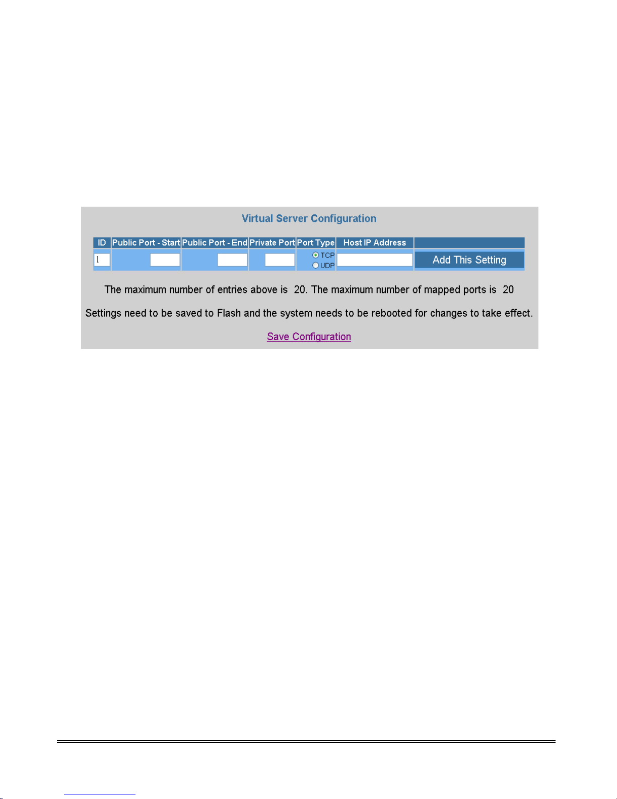
4.3.2.5 Configuration – Virtual Server
Virtual Servers are used for port forwarding from the WAN to LAN networks.
The Virtual Server Configuration page allows you to set the configuration of the Virtual Server. All
UDP/TCP ports are protected from intrusion. If any specific local PCs need to be mapped to the
UDP/TCP port on WAN side, please input the mappings here.
Note :There can be up to 20 different Virtual Server Configurations.
ID: This is the ID number corresponding to the Virtual Server configuration.
Public Port - Start: This field allows you to enter the port number of the Public Network
(WAN or external network). If you are entering a range of ports, this is the first port.
Public Port - End: This field represents the last port number in a port range. If you only want
one port number (no port range), simply enter the same number here as in the
Public Port – Start field.
Note : The maximum number of the mapped Port is 20.
Private Port: This field allows you to enter the port number of the Private Network (LAN or
internal network). In most cases, the private port number is same as public port number. This
port number cannot be seen from the WAN side.
Host IP Address: This field allows you to enter the private network IP address for the
particular server. Well-known TCP/IP ports are listed in Table below:
IEEE 802.11b Wireless ADSL Router P 69

IEEE 802.11b Wireless ADSL Router P 70

4.3.2.6 Configuration – Bridge Filtering
Bridge Filtering allows packets to be forwarded or blocked, depending on the MACbaddress. The
Bridge Filtering configuration page allows you to set the configuration of MAC filtering.
There can be up to 4 different Bridge Filtering configurations.
Source MAC: This is the Source MAC to block or from which to forward. See the next page
for instructions on how to configure this. The Source MAC must consist of 12 hexadecimal
characters.
Destination MAC: This is the Destination MAC to block or to forward to. See the next page
for instructions on how to configure this. The Destination MAC must consist of 12
hexadecimal characters.
Type: Enter the hexadecimal number for the Ethernet type field in Ethernet_II packets. For
example, 0800 is for IP protocol. The Type must consist of 4 hexadecimal characters.
Block: When block is selected, everything from the Source MAC with destination MAC will
be blocked.
Forward: When forward is selected, everything from the Source MAC will be forwarded to
the Destination MAC.
IEEE 802.11b Wireless ADSL Router P 71

Example :
Q1 : How do I forward packets with MAC address 000002fa6fab to destination MAC
000003dc8faa through IP protocol?
ANS : First go to the Bridge Filtering page under Configuration. Then type 000002fa6fab in the ID
Source MAC field, 000003dc8faa in the Destination MAC field, and 0800 in the Type field. If bridge
filtering is not already enabled, select Yes under the Enable Bridge Filtering field. Then select
Forward and click Submit.
Q2: How do I block packets from MAC address 000002fa6fab through IP protocol?
ANS : First go to the Bridge Filtering page under Configuration. Then type 000002fa6fab in the ID
Source MAC field and 0800 in the Type field. If bridge filtering is not already enabled, select Yes
under the Enable Bridge Filtering field. Then select Block and click Submit.
Q3: How do I block incoming packets with destination MAC address 000003dc8faa through IP
protocol?
ANS : First go to the Bridge Filtering page under Configuration. Then type 000003dc8faa in the
Destination MAC field, and 0800 in the Type field. If bridge filtering is not already enabled, select
Yes under the Enable Bridge Filtering field. Then select Block and click Submit.
IEEE 802.11b Wireless ADSL Router P 72

4.3.2.7 Configuration—DNS
The DNS Configuration page allows you to set the configuration of the DNS proxy.
For the DHCP requests from local PCs, the DHCP server will set the LAN port IP as the default DNS
server. Thus, all DNS query messages will come into LAN port first. The DNS proxy on the IEEE
802.11b Wireless ADSL Router records the available DNS servers and forwards DNS query messages
to one of DNS servers.
DNS Proxy Enable/Disable: When the DNS Proxy is Disabled, the LAN port does not
process the DNS query message. For the DHCP requests from local PCs, the DHCP server
will set the user-configured DNS server as the DNS server. Then all DNS query messages
will be directly sent to the DNS servers. DNS Proxy is enabled by default.
Auto Discovered: When enabled (default), the DNS proxy will store the DNS server IP
addresses obtained from DHCP client or PPP into the table. All DNS query messages will be
sent to the dynamically obtained DNS server. Select this option when the DNS Server
address is unknown but provided (automatically) by the ISP.
User Configured: When enabled, the DNS proxy will use the user-configured DNS server.
All DNS query messages will be sent to the DNS server. Enter the DNS IP in the DNS Server
field. Select this option when the DNS Server address assigned by the ISP is known. User
Configured is disabled by default.
Auto Discovery + User Configured: Selecting both options will cause the DNS proxy’s table
to have all the IP addresses of dynamically obtained and user configured DNS servers.
DNS Server: This is the user defined DNS server URL name and IP. Default is Disabled.
URL Name (Add/Delete): This is the URL name for the DNS server. This can be up to 255
characters.
Host IP (Add Only): This is the IP address of the DNS Server.
DNS Proxy Setting: This is a table of all DNS server IP addresses.
DNS Server Setting: This is a table of all DNS sever URL names.
Save Configuration: Clicking this will link the user to the Save Settings / Reboot page.
IEEE 802.11b Wireless ADSL Router P 73

IEEE 802.11b Wireless ADSL Router P 74

4.3.2.8 Configuration – Wireless
This page allows you to configure basic wireless properties and security.
SSID : The Service Set Identifier (SSID) is a unique name for your wireless network. If you
have other wireless access points in your network, they must share the same SSID.
The SSID can be up to 31 characters.
Channel : Select the appropriate channel to correspond with your network settings, between
1 and 14. All access points and wireless PC adaptors must share the same channel to
interoperate.
Range is for Channel field is 1 – 14, default is 6. If any number greater than 14 is
entered, the field will default to the value 14.
Security : The IEEE 802.11b Wireless ADSL Router provides a security encryption tool
known as WEP (Wired Equivalent Privacy). WEP is designed to provide security and privacy
equivalent to that found in a wired network. This is done by encrypting the data packets sent
between client and host with an encryption key. Both the client (PC) and the host (access
point/router) must have the same WEP key in order to communicate. The available WEP
settings are 64 bit and 128 bit. The higher the bit value on the encryption, the more secure the
data transmission. Select Enable Encryption to activate this feature.
Key Length: Choose between 64 bit (default) and 128 bit. 128 bit offers more security, but
at the cost of slower packet processing.
IEEE 802.11b Wireless ADSL Router P 75

Key 0-4: You are able to enter 4 encryption keys, only one of which is enabled at any given
time. All devices on the network must share the selected key in order to communicate with
the IEEE 802.11b Wireless ADSL Router. The key length for 64 bit is 10 hexadecimal
characters and the key length for 128 bit is 26 hexadecimal characters.
Note: If you have the WLAN Security (see next section) enabled, always choose
WEP Key ID 2. This will allow the 802.1x client and non-802.1x client to work
simultaneously in the 802.1x WLAN security Method.
Save Configuration: Clicking this will link the user to the Save Settings / Reboot page.
IEEE 802.11b Wireless ADSL Router P 76

4.3.2.9 Configuration – WLAN Security
IEEE 802.1X defines the architecture that contains three major components : Authenticator, Supplicant,
and Authentication Server.
Authenticator : Provides the mechanism to enforce authentication before a user is allowed
to access services through a certain port on the device. An authenticator can be a Wireless
Access Point, while the user is a device connected to the Wireless AP, such as a laptop. The
port refers to the wireless channel that the user and authenticator are associated with.
Supplicant : Provides the feature to request for access to the services that are accessed
through the authenticator’s port. A supplicant is a device connected to the Wireless AP, such
as a laptop.
Authentication Server : Provides the mechanism to check for the supplicant’s credentials on
behalf of the authenticator. 802.1X utilizes the existing standard security protocols, such as
Remote Authentication Dial-In User Service (RADIUS), to provide centralized user
identification, dynamic key management, and accounting.
The Wireless LAN Security page allows you to configure advanced security options.
IEEE 802.11b Wireless ADSL Router P 77

I. WLAN Security
Firmware Version : This is the version of the Wireless Security firmware.
WLAN Security Status : This field allows you to enable/disable WLAN Security.
WLAN Security Method : There are three available methods of WLAN Security:
802_1X : This option uses 802.1X for authentication with the RADIUS server
while using WEP encryption.
WPA RADIUS : This option uses 802.1X for authentication with RADIUS server
while using TKIP encryption.
WPA PSK : This option uses a pre-shared key for authentication while using TKIP
encryption.
WPA Pre-Shared Key : This is the pre-shared key for use in WPA PSK security method.
WPA Group Key Timeout (sec) : This is the time-out value for the WPA Group Key.
RADIUS Re-Auth Timeout (sec) : When this value is timed out, 802.1X will
re-authenticate every associated client.
Note: With WLAN Security enabled, select “Enable Encryption” and choose WEP Key
ID 2 on the Wireless Page (see previous section). This will allow the 802.1x client and
non-802.1x client to work simultaneously in the 802.1x WLAN security Method.
II. Primary and Secondary RADIUS Servers
Status : This is the status of the primary RADIUS server.
Shared Secret : This is the password shared between an 802.11 access point and the
RADIUS server.
IP Address : This is the IP address of the RADIUS server.
Port Number : This is the UDP port of the RADIUS server.
Response Time (3~180 sec) : This is the amount of time the 802.11 access point will wait
before it retries.
Maximum Retry (1~5) : This is the maximum amount of retry attempts to connect to the
RADIUS server before the server responds with and “authentication failure” message to the
supplicant.
Save Configuration: Clicking this will link the user to the Save Settings / Reboot page.
IEEE 802.11b Wireless ADSL Router P 78

4.3.2.10 Configuration – User Password Configuration
The User Password Configuration page allows the user or admin to set the password for the user
account.
The User Password can be up to 65 characters (excluding ‘&’).
Note: User Account cannot be used to access FTP server.
Save Configuration: Clicking this will link the user to the Save Settings / Reboot page.
IEEE 802.11b Wireless ADSL Router P 79

4.3.2.11 Configuration – Save Setting/Reboot
The Save Settings / Reboot page allows you to either save the new configuration to the flash and
reboot the IEEE 802.11b Wireless ADSL Router or simply reboot the IEEE 802.11b Wireless ADSL
Router without saving changes.
Save & Reboot: Click this to apply all changes.
Reboot Only: Do this to discard all changes since last save.
After either one of these buttons are clicked, the IEEE 802.11b Wireless ADSL Router will do the
following:
I. Save & Reboot: Two pages will appear after pressing this button. The first one states:
“Your settings are being saved and the modem being rebooted. Savereboot in progress,
please wait….” Followed by “Your settings have been saved and the modem has
rebooted. Done”
II. Reboot Only: Two pages will appear after pressing this button. The first one states:
“The modem is being rebooted. Reboot in progress, please wait….” Followed by “The
modem is being rebooted. Done.”
IEEE 802.11b Wireless ADSL Router P 80

4.3.3 Advanced Setup – Admin Privilege
The links under Admin Privilege are only accessible when user is logged in as Admin.
Regular user account does not have authorization to view or alter the content on the pages in the
Admin Privilege section.
IEEE 802.11b Wireless ADSL Router P 81

4.3.3.1 Admin Privilege – WAN Status
The WAN Status page shows the information and status of WAN PVCs.
WAN: This field displays the IP address, Subnet Mask and MAC address for the WAN
(ADSL) interface. Use the Virtual Circuit selection to select different PVCs for status
display.
Virtual Circuit: Select the Virtual Circuit that you want to release/renew, select the
appropriate option on the menu dropdown and click Execute.
IEEE 802.11b Wireless ADSL Router P 82

4.3.3.2 Admin Privilege – A T M Status
The ATM Status page shows all the statistics information of ATM cells. This page contains
information that is dynamic and will refresh every 2 seconds.
Reset Counters: This button allows user to reset the ATM Status counter.
ATM Status Fields: Tx Bytes, Rx Bytes, Tx Cells, Rx Cells, Rx HEC Errors, Tx Mgmt Cells,
Tx CLP0 Cells, Rx CLP0 Cells, Tx CLP1 Cells, Rx CLP1 Cells, Rx Errors, Tx Errors, and
Rx Misrouted Cells.
Note: For more information on HEC, Cell, CLP0, and CLP1, please refer to Appendix F:
Glossary.
IEEE 802.11b Wireless ADSL Router P 83

4.3.3.3 Admin Privilege – ADSL Configuration
The ADSL Configuration page allows you to set the configuration for ADSL protocols.
Annex Mode Config : This allows you to manually configure the IEEE 802.11b Wireless
ADSL Router for Annex A or Annex B mode by selecting User Configured and choosing the
Annex Mode in the next field.
User Selected Annex Mode : This allows you to select from Annex A and Annex B.
Trellis : Trellis Code is an advanced method of FEC (Forward Error Correction). This field
allows you to enable or disable the Trellis Code. By default, it is always enabled.
Handshake Protocol: This field allows you to select from the following ADSL handshake
protocols : Autosense – G.dmt first (default), Autosense – T1.413 first, G.dmt/G.lite, T1.413,
G.dmt, and G.lite.
Wiring Selection : This field allows you to enter the wiring selection for the RJ-11. Tip/Ring
is the default for the IEEE 802.11b Wireless ADSL Router without the inner/outer pair relay.
Available types are Auto, Tip/Ring (default), and A/A1, where Tip/Ring is the inner-most
pair of wires on the RJ11 and A/A1 is the second inner-most pair.
Bit Swapping : This field allows you to enable or disable the upstream bit swapping. Bit
Swapping is disabled by default.
IEEE 802.11b Wireless ADSL Router P 84

4.3.3.4 Admin Privilege – Route Table
The Route Table page displays the routing table and allows you to manually enter a routing entry. The
routing table will display the routing status of Destination, Netmask, Gateway, and Interface. The
interface br0 indicates the USB interface; lo0 indicates the loopback interface; ppp1 indicates the PPP
interface. The Gateway is the learned Gateway.
The Gateway field of the static route entry allows users to either enter a Gateway IP address
or select a Network Interface.
All user-defined routes retained in the CPE memory, regardless if they are already in the
Routing Table, are displayed on the same Route Table page.
All user defined route entries kept in the CPE memory during run time are saved to flash
when the user chooses to save and reboot the CPE. When the CPE restarts, it reloads all
saved user-defined routes to the CPE memory and tries to apply to the system.
IEEE 802.11b Wireless ADSL Router P 85

A user-defined route entry is added to the Routing Table whenever the system provides an
environment that makes the route entry applicable. It is removed from the Routing Table
whenever the route entry becomes not applicable. e.g. If the route entry’s Gateway is
associated with a dynamic Network Interface but the connection is not established, then the
route entry does not appear in the Routing Table. When that interface comes up later, the
route entry is then added.
If the selected Network Interface is static or dynamic and the connection is already up, then
the route entry appears in the Routing Table immediately. If there is a Gateway associated
with the selected Network Interface, then that Gateway’s IP address appears in the Gateway
field of the route entry.
If the selected Network Interface is dynamic but the connection is not established, then the
route entry does not appear in the Routing Table. When the interface comes up later, the
route entry is then added.
I. System Default Gateway Configuration
The system-wide Default Gateway provides three options: Auto (default), User-selected
Network Interface, and None.
None : This field allows you to choose to have no Default Gateway in the CPE.
Auto : This field allows you to enable the Bridge/Router to automatically decide the Default
Gateway.
User-selected Network Interface : This field allows you to select a Network Interface from a
list (PVCs, PPP Sessions, USB and LAN). This option allows you to associate the
system-wide Default Gateway to a Network Interface, static or dynamic, and provides a way
to fix the Default Gateway to a dynamic Network Interface before the interface is established.
Note : The options for this field are IP PVC0 ... IP PVC7, IP Ethernet 0, IP BridgeMux0,
and any PPP session that was created by the user.
Specify IP : This field allows you to specify the IP address of the default gateway.
II. Route Configuration
Destination : This field allows you to enter the remote network or host IP address for the
static routing.
Netmask : This field allows you to enter the Subnet Mask for the static routing.
Gateway : This field allows you to enter the IP address of the gateway device that allows the
router to contact the remote network or the host for Specified IP or select an Interface for the
Gateway.
Manually Configured Routes: This field displays the static route entries entered by the user.
IEEE 802.11b Wireless ADSL Router P 86

4.3.3.5 Admin Privilege – Learned MAC Table
Network bridges operate at the physical network layer. The purpose of a bridge is to connect two or
more networks and enable packet sharing between them. Bridges are different from routers because
they forward packets based on physical addresses, whereas routers use IP address to forward packets.
Bridges must learn all the physical (MAC) addresses of the devices so it can forward the packets
reliably. The purpose of the Learned MAC Table is to store and display these bridge-recognized
MAC addresses.
The Learned MAC Table page shows the current learned Bridge MAC table. This page contains
information that is dynamic and will refresh every 8 seconds.
Aging Timeout: This field allows you to enter the update period for the MAC table. Have this
number lower if you want a more frequent refresh rate.
Note :Range for Aging Timeout field is 0 – 32767, default is 100.
IEEE 802.11b Wireless ADSL Router P 87

4.3.3.6 Admin Privilege – RIP Configuration
RIP (Routing Information Protocol) is a management protocol that ensures that all hosts in a particular
network share the same information about routing paths. In a RIP, a host computer will send its entire
routing table to another host computer every X seconds, where X is the supply interval. The receiving
host computer will in turn repeat the same process by sending the same information to another host
computer. The process is repeated until all host computers in a given network share the same routing
knowledge. There are several components to RIP, including the authenticator, supplier, and listener.
Authenticator: Authentication is only available for RIPv2. When it is disabled, RIPv2 messages
containing authentication entries are discarded. When it is enabled, all RIPv2 messages must have
proper authentication entries, and all RIPv2 messages without verified authentication entries and all
RIPv1 messages are automatically rejected.
Supplier: The RIP Supplier has two functions:
I. It transmits route updates over every RIP Supplier interface at the interval specified by
Supply Interval (see below).
II. It transmits route updates in response to specific requests from other routers.
Listener: The RIP Listener listens and processes all RIP messages it receives from other RIP routers
and updates the host routing tables accordingly. The RIP Listener is always enabled when RIP is
enabled. By default, RIP is disabled.
The announcement messages RIP sends are based on two configuration parameters: RIP Version
number and Multicast:
The RIP messages that can be received and processed are based on two configuration parameters: RIP
Version number and Multicast:
IEEE 802.11b Wireless ADSL Router P 88

The RIP Configuration page allows you to set the configuration for the system wide configuration of
RIP. The actual RIP configuration is in the RIP Per Interface Configuration.
RIP: This field allows you to Enable or Disable the RIP session. The resulting RIP session
will monitor all network interfaces that are currently available for messages from other RIP
routers. RIP is disabled by default.
Border Gateway: RIP implements Border Gateway as specified in RFC 1058 and RFC 1723.
This limits all subnet routes and host routes to routers within that same network. Updates sent
outside that network will only include a single entry representing the entire network,
including all subnets and host-specific routes. The Border Gateway is enabled by default.
Supplier Interval: This field allows you to enter the Supplier Interval timer in seconds. This
timer specifies how often the RIP sends announcements as a RIP Supplier.
Note : Range for Supplier Interval field is 0 – 2147483647, default value is 30.
Expire Timeout: This field allows you to enter the Expire Timeout in seconds. This timer
specifies the expiration time of a route. When a route has not been updated for more than the
“expire” period of time, it is removed from the Route Table. This route is then invalidated
and remains in the internal RIP Route Table. It will be included in the RIP announcements to
let other routers know the changes.
Note : Range for Expire Timeout field is 0 – 2147483647, default is 180.
Garbage Timeout: This field allows you to enter the Garbage timer in seconds. This timer
specifies how long the expired and invalidated routes are kept in the Internal RIP Route
Table before they are removed from it.
Note : Range for Garbage Timeout field is 0 – 2147483647, default is 120.
IEEE 802.11b Wireless ADSL Router P 89

I. Advance Configuration :
The RIP Per Interface Configuration page allows you to set the configuration for each
Interface (PVCs, PPP Sessions, USB and LAN).
Interface: This field allows you to choose the Interface (PVCs, PPP Sessions, USB and LAN),
for the RIP to be configured. The available selections are: IP Ethernet 0, IP USB 0, IP
PVC0...IP PVC7, IP BridgeMux 0, and any PPP user defined sessions (maximum of 16)
Enable: This field allows you to Enable (Yes) or Disable (No) the specified interface for RIP.
Supplier: This field allows you to select the Supplier Mode (RIP Transmit).
1. Disabled: The supplier transmit is disabled.
2. V1 BC: The supplier transmits in RIPv1 Broadcast.
3. V2 BC: The supplier transmits in RIPv2 Broadcast.
4. V2 MC: The supplier transmits in RIPv2 Multicast.
IEEE 802.11b Wireless ADSL Router P 90

Listener: This field allows you to select the Listener Mode (RIP Receive)
1. V1: The listener receives the RIPv1 only.
2. V2: The listener receives the RIPv2 only.
3. V1+V2: This listener receives the both RIPv1 and RIPv2.
Current RIP Settings: This field displays the each interface’s RIP status.
IEEE 802.11b Wireless ADSL Router P 91

4.3.3.7 Admin Privilege – Misc Configuration
The Miscellaneous Configuration page allows you to set miscellaneous configurations for the
following: HTTP, FTP, TFTP, DMZ, Command Line Interface, DHCP, PPP, IGMP, and SNTP.
I. HTTP Server Access :
This field allows you to configure where these Web pages can be accessed from.
All: When this field is checked, it allows both WAN and LAN access to the Web pages. This
is the system default.
Restricted LAN: This field allows the Web pages access from LAN side.
Restricted WAN Specified IP & Subnet Mask: This field allows the Web access from
WAN side with a specify IP and subnet mask.
HTTP Server Port: This field allows you to specify the port of the Web access. . For
example, when it is changed to 8080, the HTTP server address for the LAN side is
http://10.0.0.2:8080
IEEE 802.11b Wireless ADSL Router P 92
. Range for HTTP Server port is 0 – 32767, default value is 80.

II. FTP Server :
FTP server: This field allows you to enable or disable the FTP server connection. System
default is Enabled.
Disable WAN side FTP access: This will disable WAN side access to the FTP server,
default is Disabled.
TFTP server: This field allows you to enable or disable the TFTP connection. System
default is Disabled.
An example for the TFTP client updating the vxworks.z product image code is:
III. DMZ :
DMZ: A DMZ (De-Militarized Zone) is added between a protected network and an external
network, in order to provide an additional layer of security. When there is a suspected packet
coming from WAN, the firewall will forward this packet to the DMZ host.
DMZ Host IP: The IP address of the DMZ host viewable at the WAN (external) side.
IEEE 802.11b Wireless ADSL Router P 93

IV. DHCP :
DHCP Relay :
NONE: This will disable the DHCP server. Note that this setting will override the
DHCP Server Enable/Disable on the LAN configuration page.
DHCP Server (default): Select this to activate the DHCP server.
DHCP Relay: If it is enabled, the DHCP requests from local PCs will forward to
the DHCP server runs on WAN side. To have this function working properly,
please disable the NAT to run on router mode only, disable the DHCP server on the
LAN port, and make sure the routing table has the correct routing entry.
DHCP Relay Target IP: If DHCP Relay is enabled, DHCP requests are relayed to DHCP
Target IP on the WAN side.
V. IGMP Proxy :
IGMP Proxy: This is the global setting for IGMP Proxy. If it is enabled, then the enabled
IGMP Proxy on WAN PVCs will be working. Otherwise, no WAN PVC can have IGMP
Proxy working on it. System default is Disabled.
PPP Half Bridge: When PPP Half Bridge is enabled, only one PC is able to access the
Internet, and the DHCP server will duplicate the WAN IP address from the ISP to the local
client PC. Only the PC with the WAN IP address can access the Internet. System default is
Disabled.
PPP reconnect on WAN access: If enabled, the PPP session will automatically establish a
connection when a packet tries to access the WAN. System default is Disabled.
IEEE 802.11b Wireless ADSL Router P 94

Connect PPP when ADSL link is up: If this option is enabled, the bridge/router will
connect the PPP session whenever an ADSL connection is established. If this option is
disabled, the PPP session will not connect whenever the ADSL Showtime is reached. System
default is Enabled.
Note: For more information/clarification, please refer to PPP Configuration section.
VI. SNTP :
SNTP: Simple Network Time Protocol is a efficient method of obtaining the time from a
Time Server.
Time Zone: This specifies the time zone (geographical location).
Daylight Saving Time: You can select yes to activate Daylight Savings Time.
User defined Time server: This is the time server from which the IEEE 802.11b Wireless
ADSL Router retrieves the time.
IEEE 802.11b Wireless ADSL Router P 95

4.3.3.8 Admin Privilege – TCP Status
The TCP Status page shows the statistics for all TCP connections. This page contains information that
is dynamic and will refresh every 2 seconds.
Reset Counters: This button allows user to reset the TCP Status counter.
General: Total Packets, Data Packets, Data Bytes, Out of Order Packets, Out of Order Bytes.
Discarded Packets: Bad Checksum, Bad Offset Header, Too Short.
Connections: Initiated, Accepted, Established, Closed.
IEEE 802.11b Wireless ADSL Router P 96

4.3.3.9 Admin Privilege – Admin Password Configuration
The Admin Password Configuration page allows you to set the password for administrator.
The Admin password is same as the FTP password, so it must have at least 8-characters for the FTP to
work.
The Admin password can be up to 65 characters (excluding ‘&’).
IEEE 802.11b Wireless ADSL Router P 97
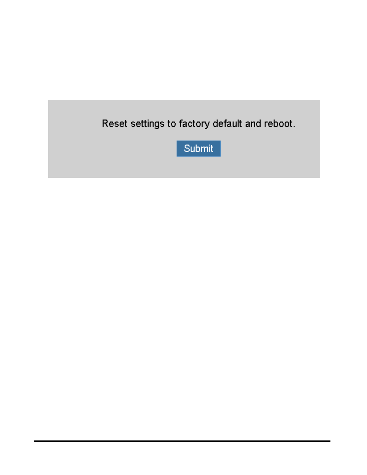
4.3.3.10 Admin Privilege – Reset To Factory Default
The Reset to Factory Default page allows you to reset the IEEE 802.11b Wireless ADSL Router to
original factory default configuration (factory.reg).
IEEE 802.11b Wireless ADSL Router P 98

4.3.3.11 Admin Privilege – Diagnostic Test
The Diagnostic Test page shows the test results for the connectivity of the physical layer and protocol
layer for both LAN and WAN sides. This page will continually refresh every 2 seconds until all tests
are complete.
I. Checking LAN Connection :
Testing Ethernet LAN Connection: This test passes if the Ethernet LAN interface is
working properly.
IEEE 802.11b Wireless ADSL Router P 99

II. Checking ADSL Connection :
Testing ADSL Synchronization: This test checks your IEEE 802.11b Wireless ADSL
Router to see if it can successfully negotiate and establish an ADSL connection with your
service provider. The test returns PASS if an ADSL connection is established.
If this test returns FAIL, please try the test again a few minutes after this test is completed.
Your IEEE 802.11b Wireless ADSL Router needs up to one minute to establish the ADSL
connection depending on your phone line quality. If this test returns FAIL, make sure your
phone line is connected to your IEEE 802.11b Wireless ADSL Router secured, and also
check with your service provider to see if your service is activated.
If this test returns FAIL, all other tests will be skipped.
III. Checking Circuit 0 For Network Connection :
Test ATM OAM Segment Loop Back: This test sends ATM OAM F5 Segment loop back
request cells to the CO. This test will pass if a response cell is received. Since some service
providers might not support this test, it could still work even if this test fails. If this test fails
consistently and the IEEE 802.11b Wireless ADSL Router seems not working, make sure the
VPI and VCI are configured correctly.
This test returns FAIL if the ADSL synchronization test failed.
Test ATM OAM End-to-End Loop Back: This test sends ATM OAM F5 End to End loop
back request cells to the central office equipment through your ADSL connection. This test
returns PASS if response cell is received. Since your service provider might not support this
test, your IEEE 802.11b Wireless ADSL Router could still be working properly even if this
test fails.
If this test returns FAIL consistently and your IEEE 802.11b Wireless ADSL Router seems to
not be working, check to make sure the VPI and VCI are configured correctly.
This test returns SKIPPED if the ADSL synchronization test failed.
Test Ethernet Connect to ATM: This test returns PASS if the ATM AAL5 module is
loaded correctly in your IEEE 802.11b Wireless ADSL Router. If this test returns FAIL, an
internal error has occurred.
This test returns SKIPPED if the ADSL synchronization does not return PASS.
Test PPPoE Connection: This test returns PASS if your IEEE 802.11b Wireless ADSL
Router can see the PPPoE server.
If this test returns FAIL, run this test again a few minutes after this test is completed,
especially if your PPPOE connection has just been improperly disconnected.
If this test consistently returns FAIL, make sure that the PPPoE settings are in the correct
configuration as instructed by your service provider, make sure the VPI and the VCI settings
of the current VC are configured correctly.
This test returns SKIPPED if the “AAL5 Connection” test does not return PASS.
IEEE 802.11b Wireless ADSL Router P 100

Test PPP Layer Connection: This test returns PASS if your login name and password have
passed authentication with your service provider.
If this test returns FAIL, run this test again a few minutes after this test is completed,
especially if your PPP connection has just been improperly disconnected. If this test
consistently fails, first make sure your login name and password are correct. Remember that
login names and passwords are case sensitive.
This test returns SKIPPED if the “PPPoE Connection” test does not return PASS and your
ADSL modem is configured as PPPoE encapsulation.
This test also returns SKIPPED if the “AAL5 Connection” test does not return PASS and
your IEEE 802.11b Wireless ADSL Router is configured for PPPOA encapsulation.
Test IP Connect to PPP: This test returns PASS if your IEEE 802.11b Wireless ADSL
Router has been assigned a valid IP address by your service provider through DHCP or your
IEEE 802.11b Wireless ADSL Router is assigned a valid IP address statically.
If this test returns FAIL, run this test again a few minutes after this test is completed. If this
test returns FAIL consistently and your IEEE 802.11b Wireless ADSL Router is statically
assigned an IP address, make sure the IP address is the correct one assigned by your service
provider.
This test returns SKIPPED if the “AAL5 Connection” test does not return PASS.
IV. Testing Internet Connection :
Ping Gateway: This test returns PASS if the gateway can be reached through a ping request.
The gateway is assigned by your service provider, or obtained from your service provider by
PPP or DHCP negotiation.
If this test returns FAIL, run this test again a few minutes after this test is completed. If this
test returns FAIL consistently and your IEEE 802.11b Wireless ADSL Router seems not
working, check to make sure your statically assigned IP address is configured correctly or the
DHCP client is enabled on with the current VC.
This test returns SKIPPED if the “IP Assignment” test does not return PASS.
Ping Prima r y D N S : This test returns PASS if the primary DNS can be reached through a
ping request. The primary DNS is assigned by your service provider or obtained from your
service provider by PPP or DHCP negotiation.
If this test returns FAIL, run this test again a few minutes after this test is completed. If this
test returns FAIL consistently and your IEEE 802.11b Wireless ADSL Router seems to not
be working, check to make sure your statically assigned primary DNS IP address is
configured correctly or DHCP client is enabled with the current VC.
This test returns N/A if there is no DNS configured.
IEEE 802.11b Wireless ADSL Router P 101

4.3.3.12 Admin Privilege – System Log
The System Log page shows the events triggered by the system. This page contains information that is
dynamic and will refresh every 5 seconds.
Clear Log: This field allows you to clear the current contents of the System Log.
Save Log: This field allows you to save the current contents of the System Log by right click
“HERE” and select “Save Target As” to save it into a text file.
The System Log records:
ADSL Layer :
ADS L Link detected
ADS L Link connected
ADS L Link disconnected
ATM Layer :
ATM detected
ATM connected
ATM disconnected
ATM setting up VPI/VCI
PPP Layer :
PPP authenticated
PPP invalid user name or password
PPP unable to connect with PPP server
IP Layer :
IP protocol up
PPP IP address
PPP Gateway IP address PPP DNS Primary IP address
PPP DSN Secondary IP address
IEEE 802.11b Wireless ADSL Router P 103

4.3.3.13 Admin Privilege – Local Code Image Update
The Code Image Update page allows you to upgrade the image code locally.
Browse the location of file, firmware.dlf or bootrom.dlf file, and click the Upload to start the update.
The IEEE 802.11b Wireless ADSL Router will reboot as part of the process of updating code.
IEEE 802.11b Wireless ADSL Router P 104

4.3.3.14 Admin Privilege – Network Firmware Image Update
The Network Firmware Image Update page allows you to upgrade the image code from the remote
FTP server.
Assume an FTP server stores the updated image firmware.dlf on Internet. Click Image Download to
initiate the updating. The IEEE 802.11b Wireless ADSL Router will reboot as part of the process of
updating code.
IEEE 802.11b Wireless ADSL Router P 105

4.3.3.15 Admin Privilege – Boot Code Image Update
Assume an FTP server stores the updated image boorom.dlf on Internet. Click Image Download to
initiate the updating. The IEEE 802.11b Wireless ADSL Router will reboot as part of the process of
updating code.
IEEE 802.11b Wireless ADSL Router P 106
 Loading...