

Page 1

DYNAMIX DC - E112
HomePNA Switch
USER’S MANUAL
Page 2

HomePNA Switch Installation and Setup Manual
FOREWORD 3
1. INTRODUCTION 4
2.
HOME
PNA SWITCH TECHNICAL SPECIFICATIONS 5
3. HARDWARE DESCRIPTION & PACKAGE CONTENTS 6
4. EQUIPMENT MOUNTING SETUP 7
4.1 R
4.2 S
4.3 S
4.4 C
ACK MOUNT 7
IMPLE STACK UP 7
TACK MOUNTING 7
ABLE SELECTION
7
5. LED INDICATORS 8
6. H
OMEPNA SWITCH CONNECTION 9
7. H
OMEPNA SWITCH AND HOMEPNA MANAGEMENT SWITCH CONNECTION 10
8. DEPLOYMENT DIAGRAM 12
9. USER INTERFACES 13
9.1 T
HE CONSOLE PORT SETUP 13
10. ICD COMMAND INDEX 14
11. SETTING VLAN FUNCTIONALITY 15
12. AUTO NOISE LEVEL FEATURE 17
13. AUTO RESET 18
14. HIGH/LOW POWER MODE 18
15. FREQUENTLY ASKED QUESTIONS (FAQ) 19
15.1 H
15.2 S
PNA 19
OME
WITCH 19
15.3 LAN 21
15.4 WAN 22
15.5 PBX 22
1
Page 3

HomePNA Switch Installation and Setup Manual
16. TROUBLESHOOTING 23
17. APPENDIX 25
17.1 H
17.2 C
17.3 DB-9 T
OMEPNA SWITCH FACTORY DEFAULTS 25
OMPLETE ICD COMMAND INDEX 25
O PS/2 CABLE DIAGRAM 26
2
Page 4

HomePNA Switch Installation and Setup Manual
FOREWORD
This guide has been constructed in a simple to follow and navigate style,
meant for VAR, SI, and reseller installation situations. This guide is also
available in Traditional Chinese, Simplified Chinese and Japanese.
Keep this guide in a safe place; it contains useful commands required for
the setup of the switches core functions in the event of a power loss or other
interruption.
Information printed within this guide is subject to change at any time
without notice. All specifications and parameters, including commands are
subject to change without notice.
Some information in this guide is acquired from the World Wide Web.
3
Page 5

HomePNA Switch Installation and Setup Manual
1. INTRODUCTION
Thank you for choosing the HomePNA Switch for your MDU Solution. We
have been on the forefront of HomePNA technology since its inception, and
will always strive to create quality, cost-effective solutions for HomePNA
installers and users.
By choosing the HomePNA Switch, you have enabled your network to have
the ultimate in flexibility. The HomePNA Switch has plenty of Ethernet ports, to
offer you many paths for upgrading your network, as well as 12 VLAN
HomePNA ports ready to plug in to your existing wiring system using current
Cat.3/RJ-11 installations.
Some highlights of the HomePNA Switch included:
Supports security with port based VLAN function.
Supports Virtual LAN (VLAN) Grouping.
Auto Noise Leveling (Automatic & Manual).
Twelve 1Mbps HomePNA Ports
Four 10/100 Mbps Base-Tx Ethernet Ports
One Console Port for HomePNA Switch.
Easy installation – no new wire required inside the building.
Easy To Use Menu System and Command Interface.
HomePNA and Ethernet ports status Monitoring.
Frequency division multiplexing for uninterrupted simultaneous
voice/data transmission.
Layer 2 Switching.
Supports Full and half duplex modes.
Store-and-Forward mechanism.
HomePNA port transmission speed up to 1Mbps
Back pressure and IEEE 802.3X compliant flow control.
Supports 8K MAC addresses entries.
Standard 19” Rack-mountable.
Less distance restriction (500 ft or 160 m) than regular Ethernet (100 m).
4
Page 6

HomePNA Switch Installation and Setup Manual
2. HOMEPNA SWITCH TECHNICAL SPECIFICATIONS
Twelve (12) HomePNA Ports
HomePNA Specs 1.1
1Mbps Speed
Transmit Distance: 500 ft Full Throughput, 1000 ft Factory Tested
LED: Link, Activity, Collision
RJ-11 Port Type for use with Twisted Pair Cable
Four (4) Ethernet Ports
10/100 Base-Tx, Auto-Negotiation
IEEE 802.3, 802.3u
LED: Link/Activity, 10/100, Full Duplex/Collision
One (1) Console Port
Baud Rate: 19200Bps, 8 Data Bits, 1 Stop Bit, No Parity, No Flow
Control
Console Management Command (Local Mode)
Manageable by HomePNA Management Switch (Remote Mode)
Physical Specifications:
AC Input: 100 - 250 VAC, 47 - 63 Hz, Internal Universal Power Supply
Power Consumption: 12W Max
Operating Temp: 0 - 50°C
Storage Temp: -25 - 70°C
Humidity: 10% - 90% Non-Condensing
Certification: FCC Part 15/68, CE, VCCI, JATE Safety Compliance &
Emissions
Weight (Net): 3.04 kg
Dimensions: 443.6 mm × 222 mm × 44 mm
Other Features
1 MB Buffer Memory
Broadcast Storm Control
Support Back Pressure and 802.3x Flow Control
Support 8K MAC Addresses Entries
Frequency Division Multiplexing for Simultaneous Voice/Data
Standard 19” Rack-mountable
5
Page 7

HomePNA Switch Installation and Setup Manual
3. HARDWARE DESCRIPTION & PACKAGE CONTENTS
Upon opening your package you should have the following items:
(1) Power Cord w/Ground
(1) HomePNA Switch
(1) Installation and Setup Manual
(4) Mounting Feet (Shelf Install)
(2) Mounting Brackets (Rack Install)
(4) Mounting Diamonds (Stack Install)
(8) Screws For Shelf or Rack Install
(1) Cat.5 Patch For Switch To Switch Connection (1.80m)
If any of these items are missing, please contact your vendor immediately
before continuing. For additional manuals or mounting feet please contact your
vendor.
Before removing the switch from the package please make sure to
remove all static devices and static electricity from your body by touching an
available metal plate or grounding point.
Your new HomePNA Switch has 12 HomePNA RJ-11 Ports, 4 Ethernet
Ports, 1 Console Module.
6
Page 8

HomePNA Switch Installation and Setup Manual
EQUIPMENT MOUNTING SETUP
2
EIA23
4.1 RACK MOUNT
The HomePNA Switch is supplied with mounting ears for easy
installation into a Standard 19” rack configuration cabinet. Simply use the
supplied ears and screws to mount it to your current rack.
1. Use the included screws to secure ears into the sides of the
HomePNA Switch in the provided pre-drilled holes.
2. Align the unit into a single 19” rack space and secure using
standard rack mount screws, the use of a nut is optional.
4.2 SIMPLE STACK UP
When mounting the HomePNA Switch on a shelf, be sure to install the
included rubber feet onto the bottom of the unit to prevent scratching of the
mounting surface, as well as to allow clearance between the switch and
surface for better airflow. Once feet are installed onto the switch unit, allow for
a clearance of at least 5 inches from rear to wall, and 1 to 2 inches on each
side, for adequate airflow.
2
EIA23
2
4.3 STACK MOUNTING
EIA23
Use the diamond shaped stackable mounts to attach to units together
from the sides. Simply apply the diamonds to each side using the included
screws to the upper holes on the bottom device, and the lower holes on the top
device.
4.4 CABLE SELECTION
Selecting the correct cable type(s) and length(s) will assist you to make
a clean and error free installation. For Ethernet uplinks and connections use
Cat.5 or higher certified cables, to minimize cross talk and noise in the cable.
For easier connection and safer operation use booted RJ-45 connections as
well. For HomePNA ports, use of shielded Cat.5 is highly recommended, but is
not a must. Refrain from using excess cable when installing to further reduce
line noise and cross talk.
7
Page 9

HomePNA Switch Installation and Setup Manual
5. LED INDICATORS
HomePNA Switch
EIA 232
LEDs Function Color Status Description
Power Power Indication Green
Ethernet Port
LNK/ACT
10/100
FDX/COL
HomePNA Port
Ethernet Port
Active
Ethernet port
Transmit And
Receive Speed
Full Duplex
Transmission And
Collision Indicator
Green
Green
Yellow
On
Off
On
Blinking
Off
On
Off
On
Blinking
Off
Power on
Power off
The Ethernet port is linked
The Ethernet port is sending
or receiving data
Port is not connected
The speed is at 100Mbps
The speed is at 10Mbps
Port is operating at full
duplex
Transmission collisions have
occurred on the Ethernet port
Port is operating at halfduplex
On The HomePNA port is linked
LINK Link Indication Green
ACT Activity Indication Green
COL Collision Indication Yellow Blinking
Blinking
Off
On
Off
The HomePNA port is not
linked
The HomePNA port is
sending and receiving data
The HomePNA port is linked
but not active
The HomePNA port is not
linked
Transmission Collision has
occurred on the HomePNA
port
Module
LEDs Function Color Status Description
SNMP SNMP Mode Green -- Reserved
XTLK
VLAN Virtual LAN status Green
Alarm -- -- -- Reserved
ID 0,1,2,3 -- -- -- Reserved
Auto noise level
status
Green
On
Off
On
Off
Auto Noise Level function is
on
Auto Noise Level function is
off
VLAN and VLAN Grouping is
on
VLAN and VLAN Grouping is
off
8
Page 10
HomePNA Switch Installation and Setup Manual
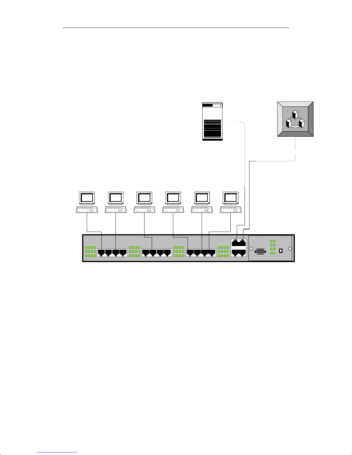
6. HOMEPNA SWITCH CONNECTION
The following illustrates the HomePNA Switch and of its ports.
Cat.5
Server
Terminal Terminal Terminal Terminal Terminal Terminal
HomePNA Switch
EIA 232
Wide Area
Network
Cat5
Figure 1
9
Page 11

HomePNA Switch Installation and Setup Manual
7. CONNECTING HOMEPNA SWITCH TO HOMEPNA
MANAGEMENT SWITCH
One of the main features of the HomePNA Switch is manageable by
other switches within the family such as SNMP Agent HomePNA Switch. The
SNMP Agent HomePNA Switch is a master management switch that serves as
master HomePNA Switches over slave HomePNA Switches such as
HomePNA Switch.
To setup the Management Switch, the slave HomePNA Switch must
contain a DB-9 type console port on the front of the unit to connect to the
Management Switch. The Management Switch Console port then uplinks to
the connecting Switch DB-9 console port. Once connected, set the first DIP
switch on the front of the Management Switch management module to the
down position, this will allow the port to communicate with the slave switch.
Once two units are connected, you can issue ICD commands to both
units through Telnet or Web interfaces for basic monitoring and maintenance.
Use the HomePNA Switch port “D” to uplink to the HomePNA Management
Switch port “C”.
This illustration shows how HomePNA Switch is connected to
HomePNA Management Switch.
Terminal Terminal Terminal Terminal Terminal
Server
HomePNA Ma nagement Switch
Terminal Terminal Terminal Termin al Terminal Terminal
HomePNA Swit ch
Figure 2
Cat. 5
Wide Area
Network
Cat. 5
Cat. 5
Patch
Cat. 5 Patch
EIA 232
DB-9 To PS/2
10
Page 12

HomePNA Switch Installation and Setup Manual
Take note of how the WAN, Server, SNMP module, and managed
switch uplink are connected to the unit. For optimal functionality and less
troubleshooting, you should connect your equipment as shown in this diagram.
The Ethernet ports on The HomePNA Management Switch are labeled A, B, C,
D; they should be connected as follow:
Port A: Connect to SNMP Module
Port B: Connect to Server or Additional WAN
Port C: Connect to Down Link Switch
Port D: Connect to Up Link Switch
Next to Ethernet ports, you will find an “Uplink” button. When connecting
port “D” to your WAN or Internet connection using cross-over cable, place the
“Uplink” button to normal or raised position. When using straight-through cable,
press down the “Uplink” button to connect the devices to the ports.
Since there is only one available Console port, the HomePNA
Management Switch cannot connect to the Console port for Console interface
and for additional switch management simultaneously. Therefore, users
should first assign an IP to the master unit through the Console interface.
Then connect the Console port to the slave switch and use Telnet to perform
modifications to the master/slave switches.
11
Page 13
HomePNA Switch Installation and Setup Manual
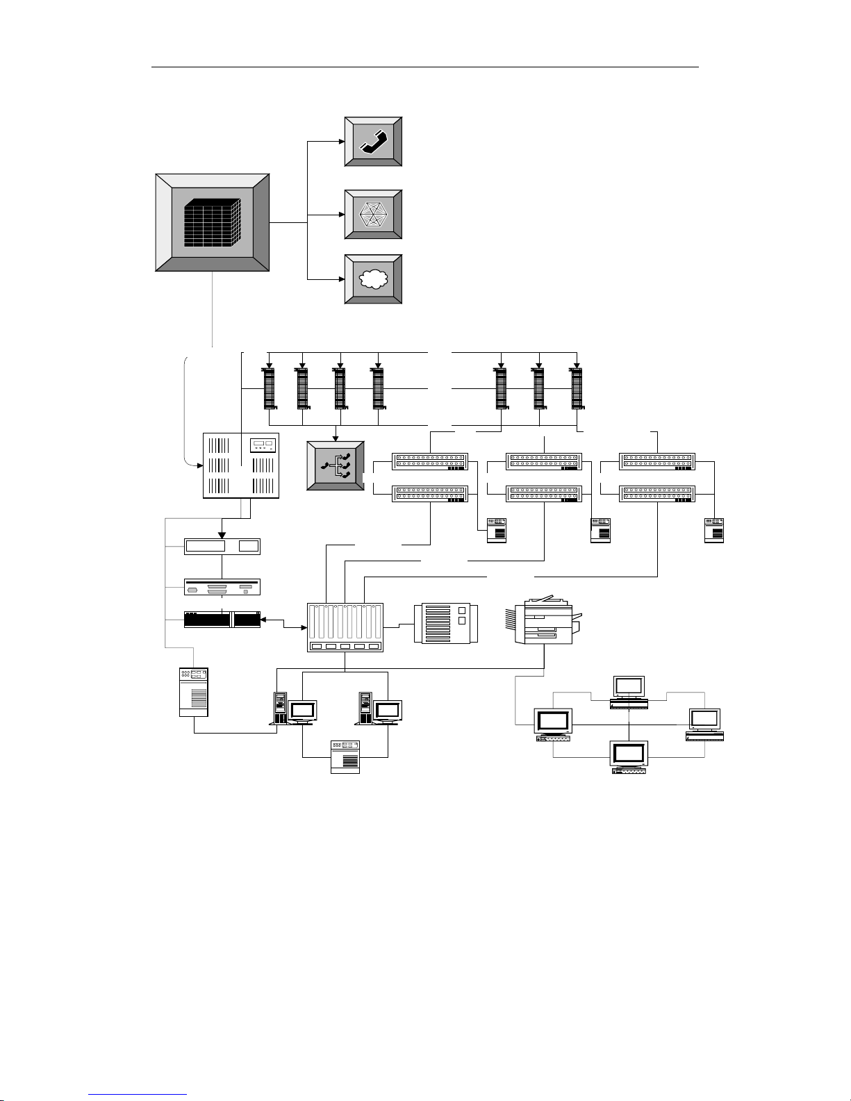
8. DEPLOYMENT DIAGRAM
POTS
Network
Private Data
CO/Telco
Inter net
This Diagram illustrates how to connect multiple
SNMP Agent HPNA Switch and HPNA Switches to
your existing Network setup.
Note: Cat. 5 is connected to PBX punchdowns and added by
use of terminal bridges on the punchdown block Lines are then
added to new punchdown blocks and from there new lines are
terminated with RJ-11 connecttors. Each set of HPNA
Switches are uplinked to each other via RJ-45 from Port C on
the SNMP Agent HPNA Switch then to Port D on HPNA Switch
. Port D of each SNMP Agent HPNA Switch is connected to
your WAN switch or ethernet device.
Each switch will give you HPNA access for 12 computers,
here we have 6 switches, giving 72 computer accesses. Be
sure to setup your Router correctly to allow these needed IP
Addresses. Also, be sure you have enough bandwidth to
satisfy user demands.
T1/T3/POTS
DSU/CSU
U.P.S.
Gateway
Router
Punch
Down
PBX
Cat.3
10/100 Switch From WAN
Server Database
Extensions
From PBX
Cat.5
Punch
Down
Cat.5
Cat.5
HomePNA Management
RJ45 RJ45 RJ45
10/100Mbps
Switch
HomePNA
Switch
To Port
D(WAN)
10/100Mbps
Disk array Network Printer
U.P.S. U.P.S. U.P.S.
10/100Mbps
RJ11RJ11 RJ11 Termintated
HomePNA Management
Switch
HomePNA
Switch
To Port
D(WAN)
Mac II
HomePNA
Management Switch
HomePNA
Switch
To Port
D(WAN)
Mac IIWorkstation
12
Figure 3
Page 14

HomePNA Switch Installation and Setup Manual
9. USER INTERFACES
9.1 THE CONSOLE PORT SETUP
This portion of the manual will discuss connection to the switches core
functions via the Console Port. For connection to the HomePNA Switch via the
console port, you must use DB-9 to Serial DB-9 cable (not included). Connect
the Console port on the unit to PC COM port using the DB-9 to Serial DB-9
cable. These cables have custom pin out assignments, and the use of other
cables or converters may cause damage or malfunction to the equipment.
Once you have connected the module to your console port, start any
terminal program, such as HyperTerminal by Hilgraeve® Software in
Windows® 98. Once you have started your terminal application, you will need
to set the terminal with the following settings:
Baud Rate Data Bits Parity Stop Bits Flow Control
19200Bps 8 None 1 None
Also note that this switch can be used with a dumb terminal that has a
DB-9 serial type port installed. If using a dumb terminal, set the DIP switches
on the terminal to the appropriate settings as listed above.
Now that you are logged into the switch, proceed to the next chapter for
an explanation of ICD commands.
13
Page 15

HomePNA Switch Installation and Setup Manual
10. ICD COMMAND INDEX
ICD Console Command & Description
ICD COMMAND COMMAND DESCRIPTION
AO## Enable Auto Noise Level on given port or all ports
when port number is not entered (Please refer to
Auto Noise Level Functionality section)
AF## Disable Auto Noise Level on given port or all ports
when port number is not entered (Please refer to
Auto Noise Level Functionality section)
A Display Auto Noise Level Status
VF VLAN Off
VO VLAN On
V Display VLAN Status
VG Set VLAN Groups (Please refer to Setting VLAN
Functionality section for complete explanation)
P Display Status of All Ports
PD## Disable given port (only for HPNA Port)
PE## Enable given port (only for HPNA Port)
C Clear Packet Counters of All Port Counter or Given
Port
PC## Display Transmit/Receive/Collision Counters in Hex
of given port or all ports when port number is not
enter
U Display Unit Information
S Save Data
RSP<S or U>,<YY> Set switch to auto reset every (1-24) hour (Please
refer to Auto Reset section for complete explanation)
RSP <F> Turn Auto Reset off
RS Reset Unit
RSW Restore MIB Agent Factory Defaults and Reset
Switch
? Display console command help
HPHS## Set Port to High Power, High Speed
LPHS## Set Port to Low Power, High Speed
HPLS## Set Port to High Power, Low Speed
LPLS## Set Port to Low Power, Low Speed
X To Exit ICD Command Mode
Symbol Key:
## HomePNA Port Number
<S> reset Switch and port
<U> reset unit
<YY> the interval between each reset; from 01 to 24 hours
14
Page 16

HomePNA Switch Installation and Setup Manual
11. SETTING VLAN FUNCTIONALITY
The VLAN function offers security and flexibility of controlling each port
access from one to another. This feature is useful in MDU and hotel situations
where you would not want each computer to be able to “see” all other
computers connected to the switch. However, in some situation you may need
to have a few ports with the capability of communicating with one another.
Such situations may arise for sharing of files, collaboration software, faster
multi-player gaming, etc.
Activating the VLAN function allows each port to be individualized, and
non-communicative to other ports on the switch in regards to local traffic.
Deactivating VLAN allows the switch to act as a normal Ethernet/HomePNA
Switch by passing along multicast and broadcast traffic to each port. Disabling
this feature would be useful when installing the switch in an office setting and
file sharing/print sharing.
Through ICD command interface you can turn the VLAN function on or
off. In ICD interface simply type “VO” to activate VLAN function, and “VF” to
deactivate the VLAN function.
HomePNA Switch also allows VLAN Grouping, which enable switch
administrators to defined ports to communicate with each other, while
remaining isolated from the other ports (outside the defined range) traffic.
The HomePNA Switch supports up to 16 different groupings, and can only be
set within the ICD Command Interface.
The command line format is as follow:
[VG][group][-][port1,…,portN]
Syntax Description
[VG] Command string.
[group]
[-]
[port1,…, portN]
Important: Each invocation of the VG for the same group will overwrite the
previously saved list for that group.
Group number (in decimal) to set, from 1
to the number of ports + trunks.
Separator between the group number and
the ports.
List of ports to be included in the group
separated by commas, the ports are
numbered from 1 to12, the trunks are
considered as ports and are numbered
using letters from A to D.
15
Page 17

HomePNA Switch Installation and Setup Manual
Note: There are no spaces between command strings.
Below are examples of VLAN Grouping through telnet:
Example 1: Place ports 1, 2, 5 and 8 to group 5 and link them to trunk port A
and B.
Command >VG5-1,2,5,8,A,B
Sample Output 1:
Setting Group 5–1,2,5,8,A,B
Example 2: Add port 10 and 11 to group 5 from example 1.
Command>VG5-1,2,5,8,10,11,A,B
Sample Output 2:
Setting Group 5-1,2,5,8,10,11,A,B
Example 3: Delete port 5 and 8 from group 5 from example 2.
Command>VG5-1,2,10,11,A,B
Sample Output 3:
Setting Group 5-1,2,10,11,A,B
Example 4: Empty group 10
Command>VG10-
Sample Output 4:
Setting Group 10 –
16
Page 18

HomePNA Switch Installation and Setup Manual
12. AUTO NOISE LEVEL FUNCTIONALITY
Auto Noise Level Adjustment is a very useful feature in HomePNA Switch
when installing under noisy line conditions, or with old wiring. The unit can
automatically compensate for noise within the line by analyzing the signal of
each port and adjust its noise floor accordingly.
You can turn on/off the Auto Noise Level feature through the ICD
command interface via Console or Telnet. The commands to activate and
deactivate this feature within the ICD command interface are “AO” and “AF”
respectively.
You can also turn on/off Auto Noise Level to individual port using ICD
commands. Please contact your vendor for more information on turning
on/off to individual port.
Occasionally you will find that the Auto Noise Level feature unable to
compensate for the noise in certain lines. This is uncommon, usually caused
by noisy lines and surroundings or bad wiring (high impedance). Signs of
trouble with the noise floor would be indicated by excessive collisions on the
affected port, or loss of link status with a sudden gain in status.
If you believe your switch needs adjustment, please contact your vendor.
17
Page 19

HomePNA Switch Installation and Setup Manual
13. AUTO RESET
The auto reset function enables the HomePNA Switch to automatically
reset the switch & ports or the whole unit periodically. By default, Auto Reset
function is off, to enable Auto Reset simple issue the “RSP” command on the
ICD command interface.
Example 1:
Set unit to auto reset switch and ports every 8 hours
RSP S,8
Example 2:
Set unit to reboot unit every 8 hours
RSP U,8
Example 3:
Turn off Auto Reset
RSP F
You may view the Auto Reset status in the Unit Information through the “U”
command at ICD Command Interface. When the unit is restored to its factory
defaults using the RSW command, Auto Reset is off.
14. HIGH/LOW POWER MODE
The HomePNA Switch contains two power modes for transmission:
low power, and high power. This setting was integrated within the switch for
installations that contain some long distance HomePNA port installations of
500 ft and 1000 ft. Power modes are adjustable on a per port basis, but with
the following side effects:
I. High Power Mode will cause much more Cross Talk within the line of
the port modified.
II. Data Rate may be slightly affected by raising the power mode, resulting
in slower transmission.
The command to change the power mode must be obtained from your
vendor.
18
Page 20

HomePNA Switch Installation and Setup Manual
15. FREQUENTLY ASKED QUESTIONS (FAQ)
15.1 H
OMEPNA
Q: What does HomePNA stand for?
A: HomePNA Stands for Home Phoneline Networking Alliance
Q: With HomePNA, Can I use my phone or fax and my Internet
at the same time?
A: Yes, you can use them at the same time.
15.2
SWITCH
Q: How many users can log into the switch through telnet at
once?
A: Telnet accepts only 1 connection at a time, however with the
Http interface you can have unlimited administrators logged in.
The console port supports only one user per session.
Q: Can I turn off ports individually?
A: Yes, Use the Console or Http Interface to do so.
Q: Can I adjust bandwidth per port?
A: No, you cannot change the throughput thresholds.
Q: Do I have to set the speeds on the Ethernet ports?
A: No, the ports are fully auto-negotiating for duplex and
10/100Mbps speed.
Q: Will the switch ever get “too busy” to handle large volumes
of data?
A: No, with the flow control mechanisms and Back Pressure
features in place, the unit will always be able to operate at
maximum throughput.
19
Page 21

HomePNA Switch Installation and Setup Manual
Q: If I turn off my HomePNA Switch, will the settings be saved?
A: YES, as long as you used the “S” save command in the ICD
command interface, all manual changes will be saved in the
event that you turn off, or lose power to your switch.
Q: Can I use one port to support multiple users?
A: Yes, the HomePNA standard supports up to 25 subscribers
per port, for shared 1Mbps access on that port, however VLAN
functionality is based per port on the switch itself. If multiple
users are connected to the same port, then they will be able to
communicate with each other regardless of the VLAN setting on
the switch.
Q: I am using my HomePNA Switch for my office network; I
cannot see the file-sharing computer. Is there something wrong
with my switch?
A: Not at all, just set the VLAN function to OFF and all ports will
be able to communicate with one another.
Q: Is the 1Mb of speed per port, or for the whole backplane?
A: The ports are capable of 1Mb full duplex max throughput per
port; the backplane can handle vast amounts of traffic.
Q: Is there a way to go back to the default passwords?
A: If you have lost or forgotten your passwords, there is a way
to set them back to the defaults, you must contact your vendor
directly for this procedure.
Q: Is the switch firmware upgradeable?
A: Yes, contact your vendor for updates.
Q: Are there serviceable parts inside?
A: No, you should not open the case at anytime, due to risk of
shock and void of warranty.
20
Page 22

15.3 LAN
HomePNA Switch Installation and Setup Manual
Q: Should the FDX/COL light stay on all the time on my
Ethernet ports?
A: Yes, if you have full duplex Ethernet running, the light will be
always on. Collisions are only present when the light flashes.
Q: Can I connect computers using HomePNA at distances
longer than 1000ft?
A: Under certain conditions it may be possible, our tests have
proved 1000ft. as acceptable.
Q: How many pairs (cable pairs) does HomePNA transmission
require?
A: One pair.
Q: Which pair runs the data in a 2 pair RJ-11?
A: It will run on either pair, just be sure that both ends of the
cable have the same wiring configuration.
Q: Can I use Cat.5 Cable to make 4 RJ-11 connections?
A: Yes.
Q: Will other types of HomePNA CPE (Customer Premises
Equipment) work with the HomePNA Switch?
A: Yes, however all Manufacturers do not guarantee the
performance of their products when used with other
manufacturer products.
21
Page 23

15.4 WAN
15.5 PBX
HomePNA Switch Installation and Setup Manual
Q: What types of WAN connections are compatible with the
HomePNA Switch?
A: Virtually any connection that has an Ethernet interface can be
used.
Q: What router should I use for best results?
A: Any router should perform well with the HomePNA switch.
Q: My router has a firewall, how do I get through remotely to my
switch to monitor and change settings?
A: In your firewall you should have a private connection-tunneling
feature, to allow direct connections between addresses on your
network and out of band workstations. Refer to your Router
User Manual.
Q: Will the switch work with all PBXs?
A: Your Switch will work with all analog PBXs and most Digital
systems, however not all PBX is compatible with this product,
you may require a low pass filter, contact your vendor for
availability.
Q: What PBX should I use for the best results?
A: Any analog PBX should work well with our system. Because
HomePNA is based on FDM (Frequency Division Multiplexing) it
sometimes conflicts with digital PBX carrier signals
22
Page 24

HomePNA Switch Installation and Setup Manual
16. TROUBLESHOOTING
This section covers some common problem areas, also known
fixes and solutions. Although the solutions offered in this section
should solve your problem, occasionally a problem might arise that
takes on a symptom of an issue, hence cannot be solved in the same
fashion. If you are unable to fix the problem after going through this
section, contact your vendor technical support for assistance.
Cross Talk Noise: Can Include Collisions and Link On/Off
Cross Talk Noise can be generated by HomePNA signals of
bundled pairs of telephone wire. When two pairs are adjacent to each
other, or twisted around each other they can create cross talk noise. A
significant amount of cross talk noise can be generated on the
HomePNA switch due to the high power output of the switch.
Therefore, when telephone pairs are close together and twisted at the
switch, the adjacent port may suffer from above problem.
Available solutions for this issue are:
1. Use Cat.5 certified cables between the MDF and
switches, including Cat.5 punchdown blocks and
shielded/booted RJ-11 connectors going into the
switch.
2. Turn on the Auto Noise Leveling Feature
3. Make manual adjustments if previous solutions failed.
Manual adjustments are covered in the “Auto Noise
Level Feature” chapter.
Reflection Noise: Caused by Un-Terminated Phone Jacks
HomePNA uses Frequency Division Multiplexing to allow
simultaneous flow of data and voice services on same pair of wires.
For this reason, your phone lines also act as data transmission lines for
the frequency range of 5.5 MHz to 9.5 MHz. Therefore, if there is any
open jack at the end of the circuit in HomePNA port, the frequency
information (data) will have nowhere to go, and reflect back into the
system, causing noise and non-function.
Solution:
Terminate those jacks using a Terminator or one of its
specifications. Otherwise, remove the excess jacks from the circuit.
23
Page 25

HomePNA Switch Installation and Setup Manual
HomePNA Switch Causes Inoperable or Malfunctioning PBX
There are many models of PBX worldwide today. Some PBX
does not correspond to certain standards when it comes to data
transmission and FDM (Frequency Division Multiplexing).
Occasionally, when a HomePNA switch is installed on a system with a
PBX, the PBX will cease to operate or the HomePNA switch stops
functioning. The problem occurs due to the two devices use FDM to
allow the sharing of the telephone wire. When one device is attached
to the other, the impedance values begin to change the expected
frequency responses, rendering both devices making one of them
unusable.
Solution:
Install an impedance matching filter to correct the frequency
domain shift. Depending on the frequency domain, type of PBX, and
amount of impedance shift a filter may be needed between the PBX and
the MDF or the CPE and Telephone set equipment. Contact your
vendor for more information on troubleshooting impedance matching
and the installations of Filter and Tester kits.
Standard Ethernet Frame Dropping
The HomePNA Switch will discard all illegal frames per Ethernet
Standards:
1. Packets Less Than 64Bytes
2. Oversized Packets Larger Than 1522Bytes
3. Bad CRC Frames
All Ports Show Collision and Flashing Link Lights
Reset the switch through the command interface or power cycle
the unit.
Cannot Connect To Internet or WAN From HomePNA Ports
Verify port and link status connecting to the router in the trunk unit. If
LED is on, ping Gateway to see if routing is configured correctly. If
LED is off, check RJ-45 cable to see if cross-over cable is being used.
24
Page 26

HomePNA Switch Installation and Setup Manual
17. APPENDIX
17.1 H
HomePNA Switch Factory Defaults
MIB Agent Factory Defaults
17.2 COMPLETE ICD COMMAND INDEX
OMEPNA SWITCH FACTORY DEFAULTS
IP Address –192.168.1.1
Gateway Address–0.0.0.0
Subnet Mask–255.255.255.0
Auto Refresh Time–15 sec
Auto Reset–OFF
Auto Noise Level Adjustment–ON
Power and Speed Mode–Low Power High Speed
Complete ICD Command index is available upon request.
25
Page 27

HomePNA Switch Installation and Setup Manual
17.3 DB-9 To PS/2 Cable Diagram
11/21/02
26
 Loading...