

Page 1
Warranty and Repair Policy
The Dynamite®T-Maxx Conversion Kit components are guaranteed against defects in workmanship and
manufacturing defects. Warranty repair will not cover units that have been modified, assembled or serviced
by an unauthorized service center.
If any part of the T-Maxx Conversion Kit needs to be replaced, package the item and ship freight prepaid to:
Horizon Service Center
Attn: Dynamite Service
4105 Fieldstone Rd.
Champaign, IL 61822
(877) 504-0233
Include your complete name and address information inside the package, as well as clearly writing it on
the outer label/return address area.
Include a brief summary of the difficulty. Date your correspondence and be sure that your name and
address appear on the enclosure. Also, please include a phone number where you can be reached during
the business day.
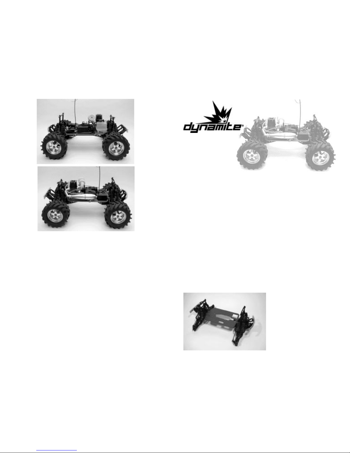
Left Side View
Right Side View
Larger pinion gears are
available to take advantage of
the additional power.
TRA4118 Clutch Bell 18T
TRA4120 Clutch Bell 20T
TRA4122 Clutch Bell 22T
Thank-you for purchasing the Dynamite
®
T- Maxx Conversion Kit. This easy-to-install
kit strengthens your T-Maxx and allows you to fit a more powerful .21-.26 size engine
(Mach 26 enginge included in some kits). By replacing the chassis with a hardanodized version and updating the drive system to metal CV (constant velocity)
joint-type axles, you can get the most out of your T-Maxx.
Kit Contents
Hard-anodized chassis Dynamite
®
polished tuned pipe Air Cleaner
Universal Metal CV shafts (4) Drive Cups (6) Hardware
Hard anodized Chassis braces F/R Center Metal Driveshafts (2)
Hard anodized engine mount Clutch nut & shims
Important
This conversion should only take a few hours to complete. It would be helpful to
complete the conversion in one day to maintain your familiarity with the assembly
process. When disassembling the T-Maxx, keep all screws and other hardware pieces
with the part they secure for easy identification. Use a threadlocking compound on
all threaded screws and nuts.
Step 1.
Remove the front and rear suspension
from the stock chassis and chassis rails.
Mount the front and rear suspension to
the new anodized chassis in the
direction shown. The front suspension
is to the right in Photo 1.
T-MAXX .21CONVERSION KIT
Instructions
Spare Part Listing
DYN2614 Complete Air Filter System: .21
DYN7410 Chassis, Conversion Kit: TMX 2.5
DYN7411 Braces, Conv Kit: TMX 2.5 (2)
DYN7412 Motor Mount, Conv Kit: TMX 2.5
DYN7413 HD Center CV Shaft Kit: TMX 2.5
DYN7414 In-line Exhaust system Polished TMX
DYN7685 CV-Driveshafts (Pr.) : TMX, EMX
DYN7689 CV-Driveshafts (Pr.) : TMX 2.5
Page 2
Step 2.
Place the vehicle upside down on the
body posts to access the lower
suspension arms. Remove the lower
suspension arm from the differential
housing to access the drive axles.
Remove the stock shafts and install
the Universal CV shafts as shown.
Replace the drive cups with the ones
provided. You may have to remove
one end of the tie rods and stabilizer
rods to access the drive axles.
Note: The setscrew that retains the drive cups must be completely removed from
the drive cup before the drive cup can be removed. Assemble in reverse order and
repeat for each suspension. Don’t forget to use threadlock on the setscrews!
Step 3.
Mount the radio system as shown. Be
sure to keep all linkages and wiring in
the proper order. When mounting the
steering servo, the output shaft
should be furthest from the front of
the chassis. Secure wiring with tie
wraps to keep them away from
moving parts.
Step 4.
Mount the fuel tank in the direction
shown.
Step 5.
Install the front and rear CV drive
shafts to the front and rear
differentials using the same
technique used in Step 2. Mount the
chassis rails to the bulkheads in the
direction shown.
Step 6.
Remove the nylon spacer on the
transmission front output shaft.
New Style T-Maxx
Slide the included hex adapter over
the front output shaft and inside the
brake disk.
Old Style T-Maxx
The hex adapter is not used.
Install the drive cups to both ends of the transmission. Slide both drive shafts into
the drive cups as you attach the transmission. Mount in the direction shown, with
respect to braking linkage.
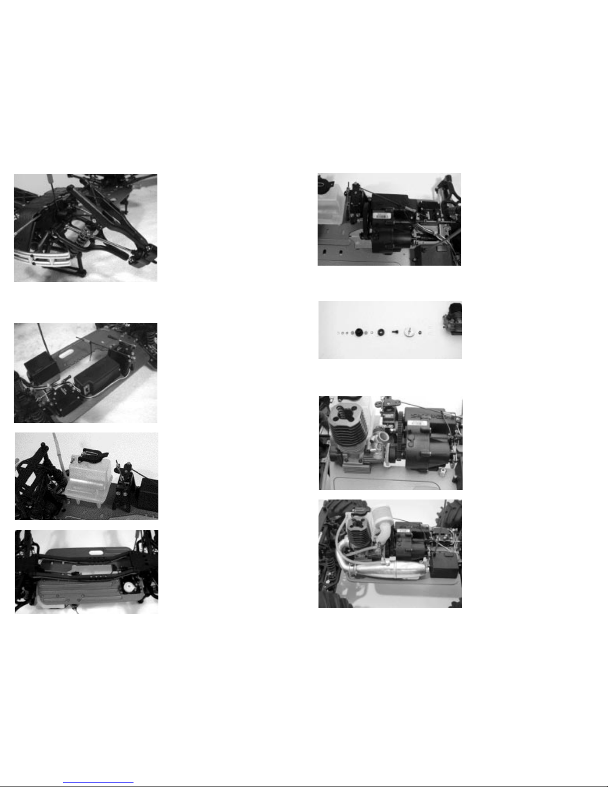
Step 7.
Assemble the clutch in the order
shown. It may be necessary to cut
away part of the engine’s crankshaft.
Be sure to leave at least three
revolutions of threads on the
crankshaft to secure the pilot shaft.
You may have to add shims behind the collet and on the pilot shaft for a proper fit.
If you purchased a kit with the Mach 26 engine included, the photo to the left shows
the exact shim placement.
Step 8.
Attach the engine mounts to the
engine as shown then secure the
assembly to the chassis. The gear mesh
between the clutch bell and the drive
gear should be as close as possible
without causing resistance. Snap the
throttle linkage to the slide carburetor.
Step 9.
Mount the exhaust manifold and tuned
pipe as shown. Be sure to secure the
manifold to the engine and pipe with
the included springs. Mount the front
of the pipe to the chassis with the
included hardware.
Attach the fuel lines to the engine
and pipe. The fuel line nearest the top
of the fuel tank attaches to the tuned
pipe. The other fuel line attaches to the
carburetor. Slide the air cleaner over
the carburetor air intake as shown.
MACH 26 Exploded View
 Loading...