

Page 1
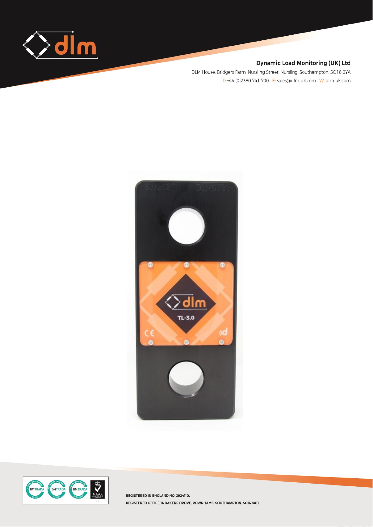
TL3.0 Telemetry Tensile Link
User Manual
Page 2
REVISION HISTORY
Revision
Date
Changes
1.0
29.10.2018
Initial Release
Page 3
CONTENTS
Section
Page
1.0
Overview
4
1.1
Networks
5
2.0
Quick Start
6
2.1
Power 6 2.2
Safe Rigging Practice
7
2.3
Pairing 8 2.4
Charging and Battery Life
11
3.0
Technical Specifications
13
3.1
Summary
13
3.2
Battery Specification
14
3.3
Wireless Specification
14
3.4
Physical Specification
14
4.0
Warranty
15
5.0
Standards and Approvals
16
5.1
CE Marking
16
5.2
FCC
Page 4
1.0 OVERVIEW
The TL-3.0 Telemetry Link is designed for use with the DLM TW-3.0 Telemetry
Handheld and any other product within the d+ range.
The TL-3.0 operates on a free band 2.4GHz frequency and utilises a bespoke
frequency hopping protocol which hops frequency 20 times per second to help
reduce interference.
The TL-3.0 is “paired” with a receiving device and can be viewed simultaneously on as
many receiving devices as required.
The TL-3.0 has a wireless range of 800m; therefore to avoid interference when
multiple TL-3.0 devices paired with their own individual display (i.e. another load cell
and handheld pair within an 800m radius) they should be configured on different
networks.
Some network setup examples are shown overleaf to illustrate the operation.
Page 5
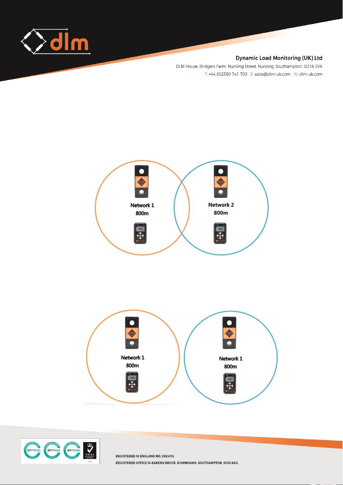
1.1 NETWORK SETTING EXAMPLES
Example 1: Using two TW-3.0 Handheld devices with two TL-3.0 Telemetry
Tensile links within range of each other.
Pair 1 needs to be paired on a network, i.e. Network 1
Pair 2 needs to be paired on a different network, i.e. Network 2
Example 2: Using two TW-3.0 Handheld devices with two TL-3.0 Telemetry
Tensile links outside of the range of each other.
Both pairs can be paired on the same network as they are far enough apart
that interference will not occur.
Page 6
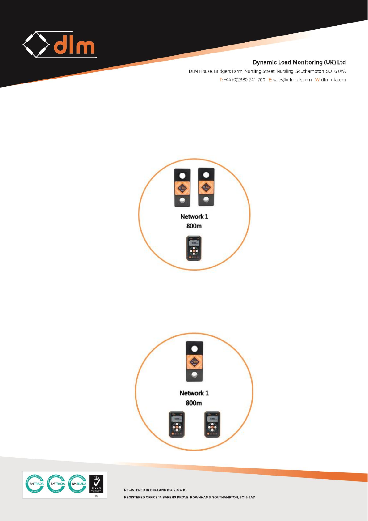
Example 3: Using one TW-3.0 Handheld device with two TL-3.0 Telemetry
Tensile links.
The TW-3.0 is set to operate on network 1 and both TL-3.0 Telemetry Tensile
Links are paired, as channel 1 and channel 2 to the TW-3.0.
Example 4: Using two or more TW-3.0 Handheld devices with one TL-3.0
Telemetry Tensile link.
One TW-3.0 is set to Master on network 1, the second TW-3.0 is set to a Slave
on network 1 and the TL-3.0 is paired on channel 1.
Page 7
2.0 QUICK START
2.1 POWER
Power On:
To power the TL-3.0 on for use follow the steps below:
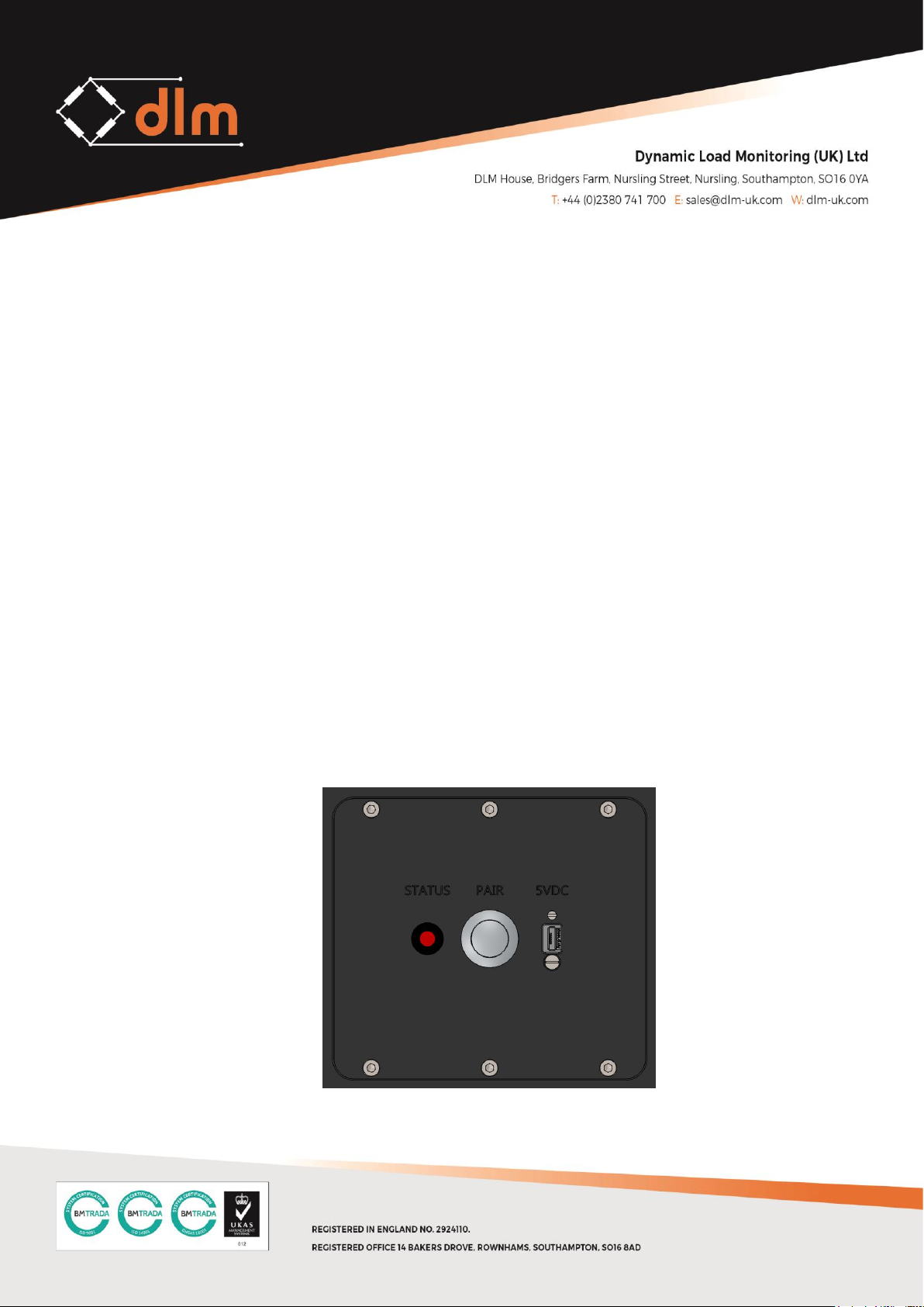
1. Press and hold the PAIR button until the LED becomes solid
2. The LED will flash once every 3 seconds if the TL-3.0 is connected to a receiving
device such as the TW-3.0 Handheld Display.
3. The LED will flash once per second if the TL-3.0 is not connected to a receiving device
Power Off:
To power the TL-3.0 off for use follow the steps below:
1. Press and hold the PAIR button, the LED becomes solid and then after 2 seconds turn
off
Page 8
Low Power Mode:
When the TL-3.0 is powered but not connected to a receiving device, it will
enter a low power mode which will look for signal once every 30 seconds. This
is to conserve battery life when the receiving device is powered off, but it is
not possible to reach the TL-3.0 to power it off.
2.2 PAIRING
The TL-3.0 needs to be paired with a receiving device, in order to establish
communication with a new device such as the TW-3.0 Handheld follow the steps
below:
1. Press the MENU button on the TW-3.0
2. Select the CHANNELS menu
3. Select the CHANNEL with which the new device is to be paired to
4. Scroll down to the PAIR menu option
5. On the device to be paired with the TW-3.0 locate the PAIRING button
6. Ensure the device is powered off
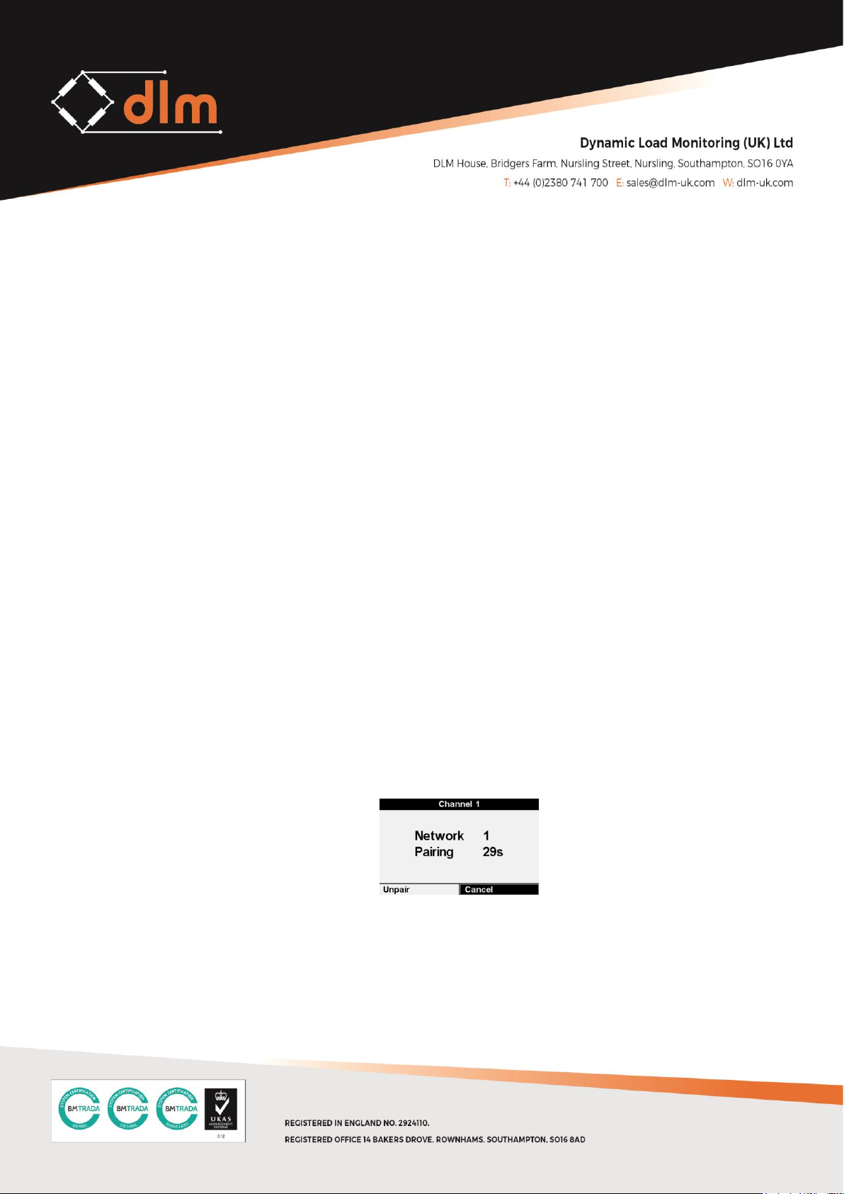
7. Press and hold the PAIR button for 8secs until the LED flashes twice per second
8. Press the PAIR function on the TW-3.0 Handheld
9. A 30 second count down timer will be initiated to search for the new device
10. Once the device has been paired the TW-3.0 will exit the pairing screen and the
LED on the new device will blink at once per second briefly
This completes the pairing process; the new device will now be present on the paired
channel.
Page 9
2.3 SAFE RIGGING
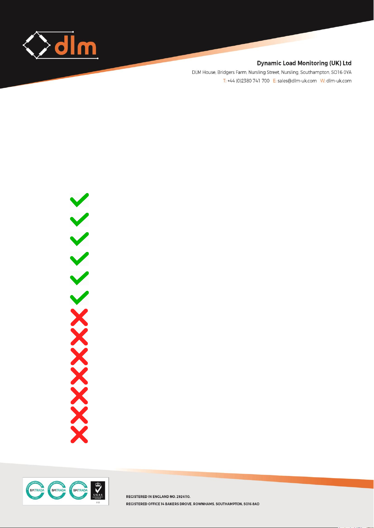
The TL-3.0 Telemetry Tensile Link makes up part of the lifting equipment during any
and all lifting applications, it is therefore necessary to ensure it is safe to use.
This information below is of a general nature only covering the main points for the
safe use of shackles. It may be necessary to supplement this information for specific
applications.
General Advice:
Store and handle shackles correctly.
Inspect shackles before use and before placing into storage.
Select the correct pattern of shackle and pin for the application.
Allow for the full resultant imposed load.
Fully tighten the pin.
Ensure the load acts through the centre line of the shackle using spacers if
necessary to meet this requirement.
Never use the shackle above its WLL
Use shackles with bent pins or deformed bodies.
Force, hammer or wedge shackles into position.
Eccentrically load shackles.
Replace the pin with a bolt
Fit pins in contact with moving parts which may loosen or unscrew them.
Shock load shackles.
Page 10
Using Shackles Safely
Do not attempt lifting operations unless you understand the use of the equipment, the
slinging procedures and the mode factors to be applied.
Do not use defective shackles or unidentified pins.
Shackles should be fitted so that the body takes the load along its centre line and is not
subjected to side bending loads. When connecting a number of sling legs, and similar
applications, position them so that they do not impose a side load on the shackle jaws. Use
spacers to position them if necessary.
With bolt and nut pins ensure the nut jams on the inner end of the thread and not on the
eye of the shackle. The bolt should be free to rotate with minimal side float. The split cotter
pin must be fitted before making a lift.
When using shackles with slings in choke hitch, or in other applications where there may be
movement, place the pin through the eye or link of the sling and never in contact with the
bight of the choke or moving parts which may cause the pin to unscrew.
In-service Inspection and Maintenance
Maintenance requirements are minimal. Keep shackles clean, the threads free of debris and
protect from corrosion.
Regularly inspect shackles and, in the event of the following defects, refer the shackle to a
Competent Person for thorough examination: illegible markings; distorted, worn, stretched
or bent body; bent pin; damaged or incomplete thread forms; nicks, gouges, cracks or
corrosion; incorrect pin; any other defect.
Page 11
2.4 CHARGING AND BATTERY LIFE
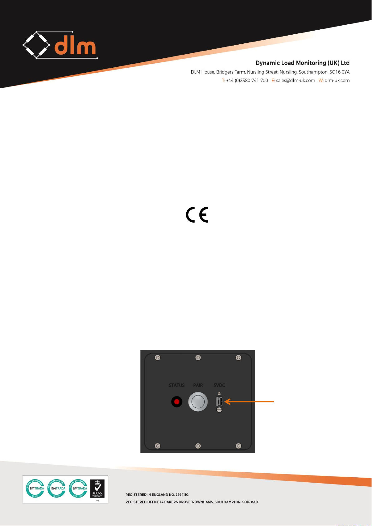
The TL-3.0 contains a single Li-Polymer battery pack which is charged via the USB
port on the front of the TL-3.0. WARNING! DO NOT CHARGE BELOW 0°C
The power source can be supplied from any PC/laptop or any mains to USB charger
plug of suitable quality. WARNING: Cheap charging devices often fail to meet the
requirements of the Electrical Equipment Regulations Act 1994, as a minimum any
charger plug must have a CE mark, shown below. It is the responsibility of the
operator to ensure any charger plug is safe to use.
The time taken to fully charge the TL-3.0 will depend on the type of charger, a simple
calculation is:
Charge Time (hours) = Battery capacity (mAh) ÷ charging current (mA)
For example:
2000mAh battery capacity charging from a laptop at 500mA:
2000 ÷ 500 = 4 hours
USB
CHARGING
PORT
Page 12
The battery life of the TL-3.0 depends on the how it is being used, the lower the
sample rate the longer the battery life will be. One example is:
Sample rate
Ambient Temperature
Battery Life
1Hz
20°C
700Hours
WARNING! DO NOT CHARGE BELOW 0°C
Page 13
3.0 TECHNICAL SPECIFICATIONS
3.1 SUMMARY
Loadcell Material
Body – 2014 T6 Aircraft Aluminium
Side Plates – Acetal (Polyoxymethylene Plastic)
Design
Designed to fit fed spec shackle / Pairing switch / Signal LED /
Charging socket
Bridge Resistance
350Ω or 700Ω
Battery
3.7V Li-Po Rechargeable battery
Battery Life
700 hours continuous (2 years storage)
Charger
USB/5VDC
Operating
Temperature
-20°C to +60°C
Handheld Display
One or more TW-3.0 displays
Frequency
2.4GHz
Range
Up to 800m line of sight
Calibration
Calibration and proof load certificates to BS EN 10002/2 1992
Protection
IP67
Packaging
Rugged watertight cast up to 50T / Custom made wooden case for
larger capacities
Approvals
CE approved and FCC compliant (pending)
Page 14
3.2 BATTERY SPECIFICATION
Minimum
Nominal
Maximum
Unit
Type
Battery pack
Quantity
1
Chemistry
Li-Po
Voltage
3.4
3.6
3.9
V
Capacity
2000
mAh
3.3 WIRELESS SPECIFICATION
Minimum
Maximum
Unit
License
2.4GHz Licence Exempt
Radio Type
Transceiver
Modulation
FHSS
Frequency
2.402
2.480
GHz
Power <100
mW
Channels
79
3.4 PHYSICAL SPECIFICATION
Specification
Unit
1T / 2T
Dimensions
214 x 81 x 16
Overall L x W x D in mm
Weight
1.0
Kg
5T
Dimensions
260 x 109 x 25
Overall L x W x D in mm
Weight
2.0
Kg
12T
Dimensions
260 x 109 x 40
Overall L x W x D in mm
Weight
2.6
Kg
17T
Dimensions
320 x 127 x 45
Overall L x W x D in mm
Weight
4.0
Kg
Page 15
25T
Dimensions
340 x 127 x 50
Overall L x W x D in mm
Weight
5.0
Kg
35T
Dimensions
370 x 149 x 50
Overall L x W x D in mm
Weight
6.5
Kg
50T
Dimensions
395 x 160 x 73
Overall L x W x D in mm
Weight
11.0
Kg
80T
Dimensions
465 x 180 x 98
Overall L x W x D in mm
Weight
18.0
Kg
100T
Dimensions
535 x 220 x 100
Overall L x W x D in mm
Weight
26.5
Kg
120T
Dimensions
535 x 240 x 100
Overall L x W x D in mm
Weight
29.5
Kg
150T
Dimensions
587 x 260 x 125
Overall L x W x D in mm
Weight
43.5
Kg
200T
Dimensions
658 x 320 x 125
Overall L x W x D in mm
Weight
62.0
Kg
300T
Dimensions
790 x 370 x 147
Overall L x W x D in mm
Weight
100.5
Kg
400T
Dimensions
950 x 500 x 175
Overall L x W x D in mm
Weight
200.0
Kg
500T
Dimensions
950 x 500 x 200
Overall L x W x D in mm
Weight
220.5
Kg
Page 16
4.0 WARRANTY
Subject to the terms and conditions set out below, Dynamic Load Monitoring (UK) Ltd
(hereinafter 'DLM' or 'the company') warrants its products against defects in materials or
workmanship for a period of one year from the date of original purchase.
Should a circumstance or condition be observed which might give rise to a claim under this
warranty; the user should immediately take the unit out of operation. The item should then
be returned carriage paid (including any and all taxes and duties) to DLM. It is advisable to
notify DLM, by telephone or fax, of the details of the case prior to dispatch.
The extent of the company's liability under the terms of this warranty shall be the repair or
replacement of the defective product, or defective part thereof, and the decision whether to
repair or replace shall be made by DLM at its sole discretion.
After completion of any remedial work / replacement, the company will return the goods
carriage paid.
Exclusions
Defects arising from the following circumstances are excluded from the benefit of this
warranty:
• Unauthorised modification;
• Misuse, mishandling, abuse;
• Improper or inadequate maintenance;
• Operation outside the environmental specifications of the product.
Page 17
5.0 STANDARDS AND APPROVALS
5.1 CE Mark
Simplified EU Declaration of Conformity for Radio Equipment Directive (2014/53/EU)
This text is provided as an example of what should be included in the user manual as per 2014/53/EU Annex VII with the name
of the manufacturer and product(s) inserted in the relevant places
This information is provided for information purposes only and the accuracy of the text is not guaranteed and may be checked
at in the relevant language version of 2014/53/EU published on the EU EUR-LEX website at https://eur-lex.europa.eu/legal-
content/EN/TXT/?uri=CELEX:32014L0053
Dynamic Load Monitoring (UK) Ltd tímto prohlašuje, že tento TL-3.0 je ve shodě se základními požadavky a
dalšími příslušnými ustanoveními směrnice 2014/53/EU.
Undertegnede, Dynamic Load Monitoring (UK) Ltd erklærer herved, at følgende udstyr TL-3.0 overholder de
væsentlige krav og øvrige relevante krav i direktiv 2014/53/EU.
Hiermit erklärt, Dynamic Load Monitoring (UK) Ltd dass sich das Gerät TL-3.0 in Übereinstimmung mit den
grundlegenden Anforderungen und den übrigen einschlägigen Bestimmungen der Richtlinie 2014/53/EU
befindet.
Käesolevaga kinnitab , Dynamic Load Monitoring (UK) Ltd seadme TL-3.0 vastavust direktiivi 2014/53/EL
põhinõuetele ja nimetatud direktiivist tulenevatele teistele asjakohastele sätetele.
Hereby, Dynamic Load Monitoring (UK) Ltd declares that TL-3.0 is in compliance with the essential requirements
and other relevant provisions of Directive 2014/53/EU.
Por medio de la presente Dynamic Load Monitoring (UK) Ltd declara que el TL-3.0 cumple con los requisitos
esenciales y cualesquiera otras disposiciones aplicables o exigibles de la Directiva 2014/53/UE.
ΜΕ ΤΗΝ ΠΑΡΟΥΣΑ, Dynamic Load Monitoring (UK) Ltd ΔΗΛΩΝΕΙ ΟΤΙ TL-3.0 ΣΥΜΜΟΡΦΩΝΕΤΑΙ ΠΡΟΣ ΤΙΣ
ΟΥΣΙΩΔΕΙΣ ΑΠΑΙΤΗΣΕΙΣ ΚΑΙ ΤΙΣ ΛΟΙΠΕΣ ΣΧΕΤΙΚΕΣ ΔΙΑΤΑΞΕΙΣ ΤΗΣ ΟΔΗΓΙΑΣ 2014/53/ΕE.
Par la présente, Dynamic Load Monitoring (UK) Ltd déclare que l'appareil TL-3.0 est conforme aux exigences
essentielles et aux autres dispositions pertinentes de la directive 2014/53/UE.
Con la presente , Dynamic Load Monitoring (UK) Ltd dichiara che questo TL-3.0 è conforme ai requisiti essenziali
ed alle altre disposizioni pertinenti stabilite dalla direttiva 2014/53/UE.
Ar šo Dynamic Load Monitoring (UK) Ltd deklarē, ka TL-3.0 atbilst Direktīvas 2014/53/ES būtiskajām prasībām un
citiem ar to saistītajiem noteikumiem,
Page 18
Šiuo Dynamic Load Monitoring (UK) Ltd deklaruoja, kad šis TL-3.0 atitinka esminius reikalavimus ir kitas
2014/53/ES Direktyvos nuostatas.
Hierbij verklaart , Dynamic Load Monitoring (UK) Ltd dat het toestel TL-3.0 in overeenstemming is met de
essentiële eisen en de andere relevante bepalingen van richtlijn 2014/53/EU.
Hawnhekk, Dynamic Load Monitoring (UK) Ltd, jiddikjara li dan TL-3.0 jikkonforma mal-ħtiġijiet essenzjali u ma
provvedimenti oħrajn relevanti li hemm fid-Dirrettiva 2014/53/UE.
Alulírott, , Dynamic Load Monitoring (UK) Ltd nyilatkozom, hogy a TL-3.0 megfelel a vonatkozó alapvetõ
követelményeknek és az 2014/53/EU irányelv egyéb elõírásainak.
Niniejszym Dynamic Load Monitoring (UK) Ltd oświadcza, że TL-3.0 jest zgodny z zasadniczymi wymogami oraz
pozostałymi stosownymi postanowieniami Dyrektywy 2014/53/UE.
Dynamic Load Monitoring (UK) Ltd declara que este TL-3.0 está conforme com os requisitos essenciais e outras
disposições da Directiva 2014/53/UE.
Dynamic Load Monitoring (UK) Ltd izjavlja, da je ta TL-3.0 v skladu z bistvenimi zahtevami in ostalimi
relevantnimi določili direktive 2014/53/EU.
Dynamic Load Monitoring (UK) Ltd týmto vyhlasuje, že TL-3.0 spĺňa základné požiadavky a všetky príslušné
ustanovenia Smernice 2014/53/EÚ.
Dynamic Load Monitoring (UK) Ltd vakuuttaa täten että TL-3.0 tyyppinen laite on direktiivin 2014/53/EU
oleellisten vaatimusten ja sitä koskevien direktiivin muiden ehtojen mukainen.
Härmed intygar Dynamic Load Monitoring (UK) Ltd att denna TL-3.0 står I överensstämmelse med de väsentliga
egenskapskrav och övriga relevanta bestämmelser som framgår av direktiv 2014/53/EU.
Hér með lýsir Dynamic Load Monitoring (UK) Ltd yfir því að TL-3.0 er í samræmi við grunnkröfur og aðrar kröfur,
sem gerðar eru í tilskipun 2014/53/EU.
Dynamic Load Monitoring (UK) Ltd erklærer herved at utstyret TL-3.0 er i samsvar med de grunnleggende krav
og øvrige relevante krav i direktiv 2014/53/EU.
Noi, Dynamic Load Monitoring (UK) Ltd, declarăm pe propria noastră răspundere că produsul TL-3.0 este în
conformitate cu cerinţele esenţiale şi celelalte prevederi aplicabile ale Directivei 2014/53/UE.
Page 19
5.2 FCC
This device complies with Part 15 of the FCC rules. Operation is subject to the following two
conditions:
1) This device must accept any interference and
2) This device must accept any interference received including interference that may
cause undesired operation
Changes or modifications not expressly approved by Dynamic Load Monitoring Ltd. could
void the user’s authority to operate the equipment.
 Loading...