

Page 1
DYNAMIC ENGINEERING
150 Dubois St. Suite C, Santa Cruz, CA 95060
831-457-8891 Fax 831-457-4793
http://www.dyneng.com
sales@dyneng.com
Est. 1988
User Manual
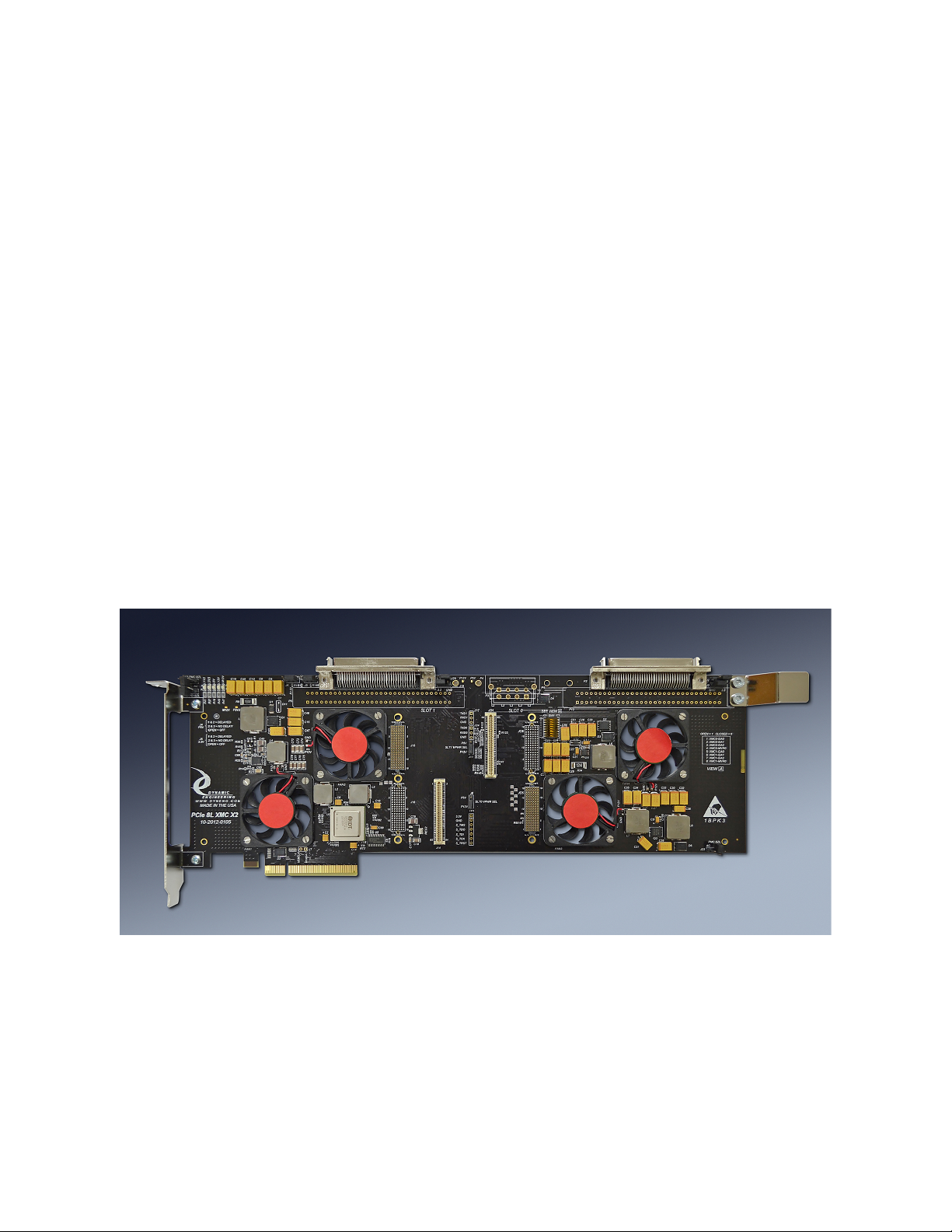
PCIe8LXMCX2
PCIe 8 Lane 2 Position XMC Compatible Carrier
Shown With PMC/SCSI rear IO connector
Revision E3 12/28/18
Corresponding Hardware: Revision C-F
Fab number 10-2012-0106
Page 2

Embedded Solutions Page 2
PCIe8LXMCX2
PCIe and XMC Compatible Carrier
Dynamic Engineering
150 Dubois St. Suite C
Santa Cruz, CA 95060
831457-8891
831457-4793 FAX
This document contains information of
proprietary interest to Dynamic Engineering. It
has been supplied in confidence and the
recipient, by accepting this material, agrees that
the subject matter will not be copied or
reproduced, in whole or in part, nor its contents
revealed in any manner or to any person except
to meet the purpose for which it was delivered.
Dynamic Engineering has made every effort to
ensure that this manual is accurate and
complete. Still, the company reserves the right
to make improvements or changes in the
product described in this document at any time
and without notice. Furthermore, Dynamic
Engineering assumes no liability arising out of
the application or use of the device described
herein.
The electronic equipment described herein
generates, uses, and can radiate radio
frequency energy. Operation of this equipment
in a residential area is likely to cause radio
interference, in which case the user, at his own
expense, will be required to take whatever
measures may be required to correct the
interference.
Dynamic Engineering’s products are not
authorized for use as critical components in life
support devices or systems without the express
written approval of the president of Dynamic
Engineering.
Connection of incompatible hardware is likely to
cause serious damage.
©2012-2018 by Dynamic Engineering.
Other trademarks and registered trademarks are owned by their
respective manufactures.
Page 3

Embedded Solutions Page 3
PRODUCT DESCRIPTION 5!
Headers and TestPoints 6!
DipSwitch Settings 7!
Options 8!
XMC Module Backplane IO Interface Pin Assignment 10!
XMC Module Jn4 Ethernet and Serial Pin Assignment 11!
APPLICATIONS GUIDE 12!
Interfacing 12!
Construction and Reliability 13!
Thermal Considerations 13!
WARRANTY AND REPAIR 14!
Service Policy 14!
Out of Warranty Repairs 14!
For Service Contact: 14!
SPECIFICATIONS 15!
ORDER INFORMATION 16!
Table of Contents
Page 4

Embedded Solutions Page 4
FIGURE 1! PCIE8LXMCX2 JN4/JN6 INTERFACE STANDARD 10!
FIGURE 2! PCIE8LXMCX2 JN4 ETHERNET, SERIAL 11!
List of Figures
Page 5

Embedded Solutions Page 5
Product Description
PCIe8LXMCX2 is part of the Dynamic Engineering PCI and XMC Compatible family of
modular I/O components. PCIe8LXMCX2 adapts 2 XMC’s to one PCIe slot.
Embedded applications frequently require real time processing coupled with special
purpose IO. With PCIe8LXMCX2’s two XMC positions; a PrXMC can be matched with
another XMC to make a high bandwidth processing node. The PrXMC can
communicate with the host for set-up, and then use the local bus to control and transfer
data with the special purpose IO card.
Special features:
• 24 lane Gen1/2 compliant Switch
• 8 lanes allocated to PCIe “gold finger” interface. 8 lanes each to the XMC’s
• Switch can store and forward locally to communicate directly between the XMC’s
• Voltage monitors, each with LED’s on plus 12V, minus 12V, plus 5V, plus 3.3V, and
switch power [1.0V]
• 10A regulator for XMC 3.3V and 5V supplies. Shunts for Delayed, not Delayed, Off
• Selection switch for VPWR [12V or 5V] per XMC. Option for hardwired 5V or 12V
• Front panel connector access through PCI bracket
• User IO [Jn4 and/or Jn6] available through one of two cable connectors (DIN IDC or
SCSI II compatible) Spare pins on SCSI connector can be shunt selected to power
or ground.
• Cooling cutout for increased airflow to XMC’s
• Optional Fan(s) for increased airflow
• Optional Ethernet connectors to support XMC’s with Ethernet
• Optional Serial Port connectors to support XMC’s with Serial Ports
• JTAG programming support
• DIP switch to select global addressing on XMC’s
PCIe8LXMCX2 is ready to use with the default settings. Just install the XMC onto
PCIe8LXMCX2 and into the system.
Page 6

Embedded Solutions Page 6
Headers and TestPoints
J6 and J11 are used to select the VPWR source for position 0 and 1 respectively.
When the Shunt closes 1-2 – 12V is selected. With 2-3 closed 5V is selected. FET’s
are used to provide a low impedance path from the power supplies to VPWR for each
position. Options are in place on the PCB to allow hardwired selections for clients who
prefer a fixed voltage. The headers are not installed when the fixed voltage option is in
place. With pin 2 open VPWR will be open.
J12, 13, and 23 are used to select the bezel grounding option. 1-2 selects AC coupled,
2-3 selects DC coupled and open is open. J12 = PCIe Bezel. J13 = Slot 0. J23 = Slot
1.
J1 is an optional header for SMB connection. Pin 1 is data and pin 2 is clock. Both are
pulled up. 3rd party tools can be used to see the “innards” of the switch. Usually not
needed but handy if you are doing development or want to talk through the switch to the
XMC positions.
TP1 is an optional JTAG header used to connect to XMC 0. The pin definitions are in
the silk. 1: 3.3V, 2: GND, 3: TMS, 4: TDO, 5: TDI, 6: TCK, 7: TRST
J2 & J19 control the voltage on 33,67 of P2 and P7 respectively when the SCSI
connector options are selected. 1-2 selects 3.3V and 2-3 selects ground on those pins.
The shunt and traces are rated for 1A. Not fuse protected.
J3 & J20 control the voltage on 34,68 of P2 and P7 respectively when the SCSI
connector options are selected. 1-2 selects 3.3V and 2-3 selects ground on those pins.
The shunt and traces are rated for 1A. Not fuse protected.
J16 & J17 provide the serial port connections when installed. J16 is for Serial Port 0
and J17 is for serial port 1 on XMC0. Pin 1 is TX and pin 2 is Rx. Pin 3 is a ground
reference. Standard serial connections IAW 2.15 from Pn4 when this option is installed
J10 & J18 provide the ethernet port connections when installed. J10 is for ethernet Port
0 and J18 is for ethernet port 1 on XMC0. Standard Ethernet connections IAW 2.15
from Pn4 when this option is installed
P3, 4, 6 are optional power connectors to allow for added 12V power to be used by the
PCIe8LXMCX2. The PCIe gold fingers allow for about 60W of power to be consumed
by the board across all XMC voltages including power supply losses. In many cases
Page 7

Embedded Solutions Page 7
the power budget is more than sufficient. If your XMC’s require more power please
request one of the optional power connectors [discrete wire, 4 wire standard PC vert or
horizontal] to increase the 12V available. Both 12V entry points are diode coupled to
prevent the current back-feeding when an external or other supply is added.
P3: 1-2 = gnd, 3-4 = 12V. P4,6: 1= 12V, 2-3 = gnd.
J4, J5 control the power sequencing for 3.3V and 5V respectively. 1-2 selects a
delayed start-up of the power supply, 2-3 for immediate start-up [based on 12V
available] and open is off [used for power savings when a supply is not required. Added
with Rev 03 boards. Resistor options are available to hardwire the selection.
DipSwitch Settings
Switch 1: Global Address Settings
Position 1-3 corresponds to XMC0 GA0-2. When closed the signal is ‘0’. When open
the signal is ‘1’.
Position 4 corresponds to XMC0-MVR0. When closed the signal is ‘0’. When open the
signal is ‘1’.
Position 5-7 corresponds to XMC1 GA0-2. When closed the signal is ‘0’. When open
the signal is ‘1’.
Position 8 corresponds to XMC1-MVR0. When closed the signal is ‘0’. When open the
signal is ‘1’.
Page 8

Embedded Solutions Page 8
Options
Dynamic Engineering offers multiple versions of the PCIe8LXMCX2design.
In addition to the basic bridged version there are options for Ethernet, Fan, Serial ports,
and minimization.
The PCIe8LXMCX2 features cooling cutouts designed to support the addition of a fan in
one or two positions for each XMC. On PrXMC's and other XMC’s with high thermal
loads the fan option is a good idea. On cards with a lower thermal profile the fan is not
needed. The fan produces 5 CFM in a small area to create a high LFM rating suitable
for most cooling requirements. The fan used has a relatively low noise rating for quiet
operation. Position 1 is closest to the PCI bezel and position 2 is closer to the XMC
connectors. For position 3 and position 4 locations continue counting left to right.
Some XMC’s support Ethernet connections over the J04 connector with pins specified
by the PICMG standard 2.15. PCIe8LXMCX2 supports Ethernet capable cards with an
optional two-position RJ45 connector on the top edge of the card. Slot 0 has this
option.
Some XMC’s support serial channels on J04 with pins specified by by PICMG standard
2.15. PCIe8LXMCX2 supports serial capable cards with an optional pair of header
connectors. Slot 0 has this option.
In addition PCIe8LXMCX2 has two options for Jn4/Jn6 signal routing. VME style 2x32
pin header [shown] or a SCSI style connector.
Please mix and match options, as you need them.
Page 9
Embedded Solutions Page 9
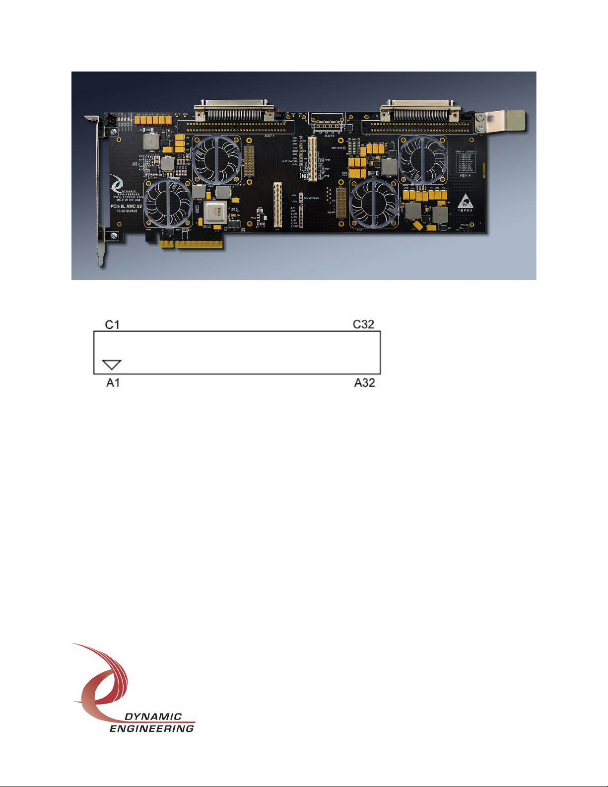
The “VME” connectors are oriented as shown by the pads under the SCSI connectors in
the picture and the diagram. Pin C1 is the lower left corner pin. Pin C1 corresponds to
the cable wire number 1 for a standard header inserted into the connector on
PCIe8LXMCX2. The mating part number is 120-964-455 Panduit, DIN-IDCA-64CSBTG30 Robinson Nugent, Berg also has a part which is slightly taller.
Cables and breakouts are available from Dynamic Engineering – Please see DINterm64
and DINribn64 or HDEcabl68 and HDEterm68 products from the Dynamic Engineering
website.
Page 10

Embedded Solutions Page 10
XMC Module Backplane IO Interface Pin Assignment
The figure below gives the pin assignments for the XMC Module IO Interface – from Jn4
and/or Jn6 to the PCIe8LXMCX2 connectors. Also see the User Manual for your XMC
board for more information. Please note that P2 or P13, P7 or P5 are installed not both.
DIN IDC [P13,P5] SCSI II [P2,P7] Jn4 Jn6
A1 C1 1 35 3 1 B1 A1
A2 C2 2 36 4 2 E1 D1
A3 C3 3 37 7 5 C2 C1
A4 C4 4 38 8 6 F2 F1
A5 C5 5 39 11 9 B3 A3
A6 C6 6 40 12 10 E3 D3
A7 C7 7 41 15 13 C4 C3
A8 C8 8 42 16 14 F4 F3
A9 C9 9 43 19 17 B5 A5
A10 C10 10 44 20 18 E5 D5
A11 C11 11 45 23 21 C6 C5
A12 C12 12 46 24 22 F6 F5
A13 C13 13 47 27 25 B7 A7
A14 C14 14 48 28 26 E7 D7
A15 C15 15 49 31 29 C8 C7
A16 C16 16 50 32 30 F8 F7
A17 C17 17 51 35 33 B9 A9
A18 C18 18 52 36 34 E9 D9
A19 C19 19 53 39 37 C10 C9
A20 C20 20 54 40 38 F10 F9
A21 C21 21 55 43 41 B11 A11
A22 C22 22 56 44 42 E11 D11
A23 C23 23 57 47 45 C12 C11
A24 C24 24 58 48 46 F12 F11
A25 C25 25 59 51 49 B13 A13
A26 C26 26 60 52 50 E13 D13
A27 C27 27 61 55 53 B15 A15
A28 C28 28 62 56 54 E15 D15
A29 C29 29 63 59 57 B17 A17
A30 C30 30 64 60 58 E17 D17
A31 C31 31 65 63 61 B19 A19
A32 C32 32 66 64 62 E19 D19
33 67 Open, +3 or GND via J2,19 silk screen defined
34 68 Open, +3 or GND via J3,20
FIGURE 1 PCIE8LXMCX2 JN4/JN6 INTERFACE STANDARD
Read table:
P13-C1 = P2-35 = Pn4-1
P13-A1 = P2-1 = Pn4-3 etc.
With Jn6: Pins: A, B, D, E of rows 2, 4, 6, 8, 10, 12 ,14, 16, 18 are grounded
Page 11

Embedded Solutions Page 11
XMC Module Jn4 Ethernet and Serial Pin Assignment
Ethernet[J10,18] Serial[J16,J17] Pn4 Slot 0
11 14 1 2
12 15 3 4
5 6
13 17 7 8
16 18 9 10
11 12
21 24 13 14
22 25 15 16
17 18
23 27 19 20
26 28 21 22
23 24
25 26
13 27 28
23 29 30
31 32
12 33 34
22 35 36
37 38
39 40
41 42
43 44
45 46
47 48
49 50
51 52
53 54
55 56
57 58
59 60
61 62
63 64
FIGURE 2 PCIE8LXMCX2 JN4 ETHERNET, SERIAL
The channel number is shown then the pin number. For example on the ethernet
connectors J10 and J18, there are two ports. Port 1 [J10] pin 1 is tied to Pn4 pin 1, Port
2 pin 8 is tied to pin 22 of Pn4. When the Ethernet and Serial options are installed the
corresponding pins on Jn4 are no longer connected to the SCSI or VME connectors.
The unaffected pins are still connected.
Page 12

Embedded Solutions Page 12
Applications Guide
Interfacing
Some general interfacing guidelines are presented below. Do not hesitate to contact the
factory if you need more assistance.
Installation
The XMC’s are mounted to the PCIe8LXMCX2 prior to installation within the chassis.
XMC connectors are rated for 50 insertion cycles and putting less rotational stress on
the connectors is a good idea. It is recommended to remove the PCIe bezel to allow
installation vertically onto the mating connectors. [you can leave the bezel in place and
rotate the XMC onto the mating connectors but this will put some side force on the
connectors and is not recommended]. The rear slot does not have the bezel interaction
and can be mounted directly.
Be careful when removing to restrict the amount of rocking used. Slowly walk the board
out of the connector. The connectors are SMT on both sides and undue stress can
fatigue the joints causing premature failure.
There are four mounting locations per XMC. Two into the XMC mounting bezel, and
two for the standoffs near the XMC bus connectors. For proper contact and operation
during vibration it is recommended to use the fasteners.
Start-up
Make sure that the "system" can see your hardware before trying to access it. Many
BIOS will display the PCI devices found at boot up on a "splash screen” with the
VendorID and CardId for the XMC installed and an interrupt level. If the information is
not available from the BIOS then a third party PCI device cataloging tool will be helpful
Watch the system grounds. All electrically connected equipment should have a failsafe common ground that is large enough to handle all current loads without affecting
noise immunity. Power supplies and power consuming loads should all have their own
ground wires back to a common point.
Power all system power supplies from one switch. Connecting external voltage to
the PCIe8LXMCX2 when it is not powered can damage it, as well as the rest of the host
system. This problem may be avoided by turning all power supplies on and off at the
same time. This applies more to the XMC’s installed onto the PCIe8LXMCX2 than the
Page 13

Embedded Solutions Page 13
PCIe8LXMCX2 itself, and it is smart system design when it can be achieved.
Construction and Reliability
PCIe8LXMCX2 is constructed out of 0.062 inch thick high temp RoHS compliant FR4
material. Cooling cutouts are designed into the product for improved air flow to the
XMC sites. The components on the PCIe8LXMCX2 are tied into the internal power
planes to spread the dissipated heat out over a larger area. This is an effective cooling
technique in the situation where a large portion of the board has little or no power
dissipation.
A fan option is available for high thermal load XMC’s or for a chassis with a lack of air
circulation.
Surface mounted components are used. The connectors are SMT for the XMC bus and
through hole for the IO.
The XMC Module connectors are keyed and shrouded with Gold plated pins on both
plugs and receptacles. They are rated at 1 Amp per pin, 50 insertion cycles. These
connectors make consistent, correct insertion easy and reliable. Please be aware the
connectors are somewhat delicate compared to PMC and other mezzanine connector
types.
The XMC Module is secured against the carrier with the XMC connectors. It is
recommended, for enhanced security against vibration, that the XMC mounting screws
are installed. The screws are supplied with the XMC from the OEM. Dynamic
Engineering has screws, standoffs, blank bezels and other XMC hardware available at a
reasonable cost if your XMC was not shipped with some of the required attachment
hardware or if it has been misplaced.
Thermal Considerations
If the installed XMC has a large heat dissipation; forced air cooling is recommended.
The zero slot Fan option can provide plenty of cooling power should your XMC require
it.
Page 14

Embedded Solutions Page 14
Warranty and Repair
Please refer to the warranty page on our website for the current warranty offered and
options.
http://www.dyneng.com/warranty.html
Service Policy
Before returning a product for repair, verify as well as possible that the suspected unit is
at fault. Then call the Customer Service Department for a RETURN MATERIAL
AUTHORIZATION (RMA) number. Carefully package the unit, in the original shipping
carton if this is available, and ship prepaid and insured with the RMA number clearly
written on the outside of the package. Include a return address and the telephone
number of a technical contact. For out-of-warranty repairs, a purchase order for repair
charges must accompany the return. Dynamic Engineering will not be responsible for
damages due to improper packaging of returned items. For service on Dynamic
Engineering Products not purchased directly from Dynamic Engineering contact your
reseller. Products returned to Dynamic Engineering for repair by other than the original
customer will be treated as out-of-warranty.
Out of Warranty Repairs
Out of warranty repairs will be billed on a material and labor basis. Customer approval
will be obtained before repairing any item if the repair charges will exceed one half of
the quantity one list price for that unit. Return transportation and insurance will be billed
as part of the repair and is in addition to the minimum charge.
For Service Contact:
Customer Service Department
Dynamic Engineering
150 DuBois St. Suite C
Santa Cruz, CA 95060
831-457-8891 831-457-4793 fax Internet Address support@dyneng.com
Page 15

Embedded Solutions Page 15
Specifications
Logic Interfaces: PCIe up to 8 lanes per XMC Gen1 and Gen2 compliant switch and
clock buffer.
Access types: PCIe TLP transactions. MSI interrupts.
CLK rates supported: Gen1 and Gen2
Software Interface: switch is auto configured and usually will not require any user
intervention.
Initialization: switch selections for VPWR, bezel grounding, and cable options
Interface: XMC front bezel via PCIe bracket and User IO connector via DIN or
SCSI connector
Dimensions: full length PCIe board with offset PCI card guide support.
Construction: High Temp FR4 Multi-Layer Printed Circuit, Through Hole and
Surface Mount Components.
Page 16

Embedded Solutions Page 16
Order Information
standard temperature range -40ó85øC
PCIe8LXMCX2 full length PCIe card with 2 XMC positions DIN
connectors installed. User VPWR selection
http://www.dyneng.com/PCIe8LXMCX2.html
-FAN(1,2,3,4)R [fan installed in position 1 or 2 or 3 or 4 or
combinations] “R” for rear mounted higher velocity
fans(~8 CFM). Non “R” boards use “Zero Slot” fans
with ~ 5CFM.
-ENET/SER [ethernet and serial port connectors installed and
connected to Jn4]
-ROHS [ROHS compliant parts and process]
-XIO Install Jn6 connectors as well as Jn4
-XIOExc Install Jn6 connectors without Jn4
-SCSI Install SCSI connectors instead of DIN
-NC Do not install DIN or SCSI connectors
-VPWR Use to hardwire VPWR setting to be 5V or 12V per
XMC site [-5V0 for 5V in position 0]
-5VXXX, -3VXXX XXX = ND [no delay], DEL[delay], OFF [ power supply
disabled] for hardwired options instead of user
selectable
-DD, -DDV, -OT Options to add Disk Drive or Disk Drive Vertical or
Screw Terminal [OT] style connectors
HDEterm68 http://www.dyneng.com/HDEterm68.html
68 pin SCSI II to 68 screw terminal converter with DIN
rail mounting.
Page 17

Embedded Solutions Page 17
HDEcabl68 http://www.dyneng.com/HDEcabl68.html
SCSI cables with latch blocks or thumbscrews and
various lengths are available. Custom lengths can be
ordered.
DINterm64 http://www.dyneng.com/DINterm64.html
64 pin ribbon cable to to 64 screw terminal converter
with DIN rail mounting.
DINribn64 http://www.dyneng.com/DINribn64.html
64 pin ribbon cable with strain relief. 50-2012-0101XX.YY.ZZ Substitute XX = major, YY = minor, ZZ =
units . For example 1.0.FT = 1 Ft long. 1.6Ft is 1
Foot 6”. Metric and English units are acceptable.
36” is the default length if XX.YY.ZZ is left off.
All information provided is Copyright Dynamic Engineering
 Loading...