

Page 1
WRAPPER FOR FREE STANDING ICEMAKER
INSTALLATION INSTRUCTIONS
Before you begin, read these instructions completely and carefully.
Getting Started
Remove packaging and retain until installation is complete.
CAUTION:
The surface on which the grill cart and Icemaker are located must be at and level. Icemaker should be
installed near water and drain supply. All plumbing must be out of the way of any foot trac.
Note: Wrapper must be installed on the Icemaker and attached to the grill cart before the grill head is
installed on the cart.
WARNING!
Some parts have sharp edges; care must be taken when handling the various components to avoid injury.
Please read safety information provided in these instructions before beginning assembly. Wear gloves
when handling.
Contents
Part Description Qty
Hardware Kit Includes:
Protective Grommet, 2.50 Diameter
Protective Grommet, 1.25 Diameter
Machine Screw 10-24 X 1-1/8
Sheet Metal Screw 10-24 X 1/2
Hex Bolt 1/4-20 X 1/2
Nut, Hex 1/4-20
Nut, Tinnerman U-nut #10-24 MS
Machine Screw 10-24 X 3/8
7” Cable Tie
Installation Instructions
Assembly instructions for Freestanding
application:
Tools Required
Phillips Screwdriver
1
1
1
8
2
2
2
4
4
1
5/16 Socket/Nutdriver and 5/16 Wrench
Safety Glasses
Work Gloves
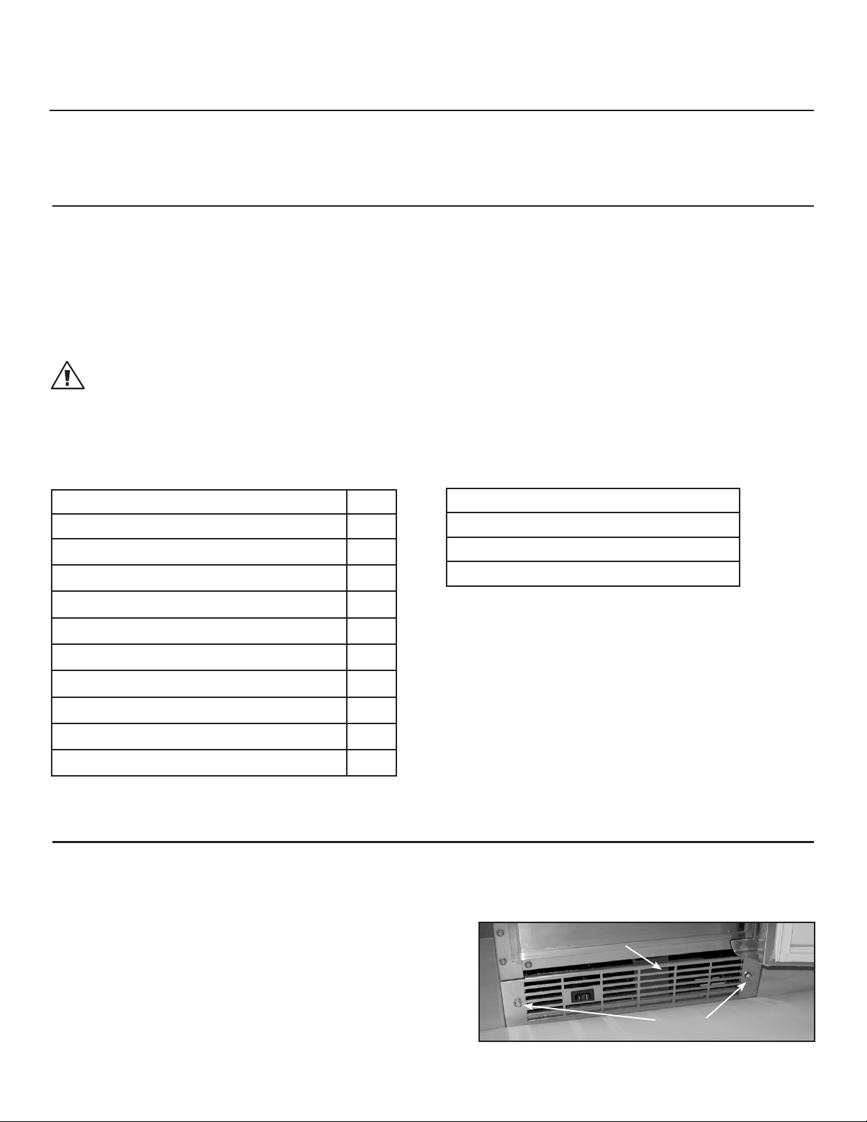
Loosen (2) screws on front bottom grill cover 1.
(Fig. 01) approx. 1/8”. (No need to remove screws.)
Note: Installation of optional drain pump (sold
separately - model # RF15I-P) must be done
before installation of wrapper.
Front bottom grill cover
Screws
Fig. 01
1
Page 2
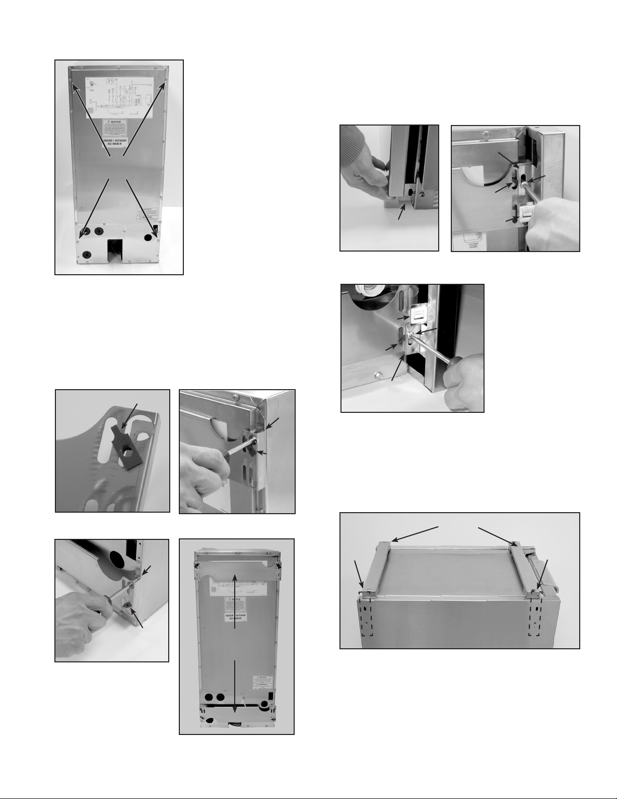
Remove (4) screws on back panel of Icemaker as 2.
shown (Fig. 02). (Retain screws for re-use.)
Place the left side panel on the unit by sliding the 4.
bottom front ange behind the front grill plate
(Fig. 07). Then lift the rear of the panel so the U-nut
holes are visible in the slotted holes of the upper
and lower rear anges of the panel. Install machine
screws (10-24 X 3/8) into U-nuts as shown (Fig. 08
and 09). Do not tighten at this point.
Upper rear ange
Screws
Fig. 02
Install 2 Tinnerman U-Nuts on Icemaker Adapter 3.
(Fig. 03) and attach to upper area of Icemaker as
shown (Fig. 04). Repeat for the bottom location
(Fig. 05). Tighten all screws at this point. See
Fig. 06 for nal placement.
U-nut
Icemaker
adapter
Upper
screw
U-nut
near top
Female catch
U-nut
Lower rear ange
Repeat Step 4 for the other side panel. 5.
Place both top risers on top of unit as shown in 6.
Fig. 10.
Bottom front
ange
Fig. 07
Fig. 09
Screw
U-nut
Female catch
Fig. 08
Screw
Fig. 03
Fig. 05
Lower
screw
U-nut
near oor
Fig. 04
Icemaker
adapters
Fig. 06
Ensure
holes
are
aligned
Top risers
Side view
Fig. 10
Ensure
holes
are
aligned
2
Page 3
Using screws provided (10-24 X 1-1/8), attach riser 7.
to the side panels. Take note of the alignment of the
holes on the riser and side panel (Fig. 11).
Ensure
holes
are
aligned
Fig. 11
Adjust the side panels to be level with the top of the 8.
Icemaker, then tighten all ange screws.
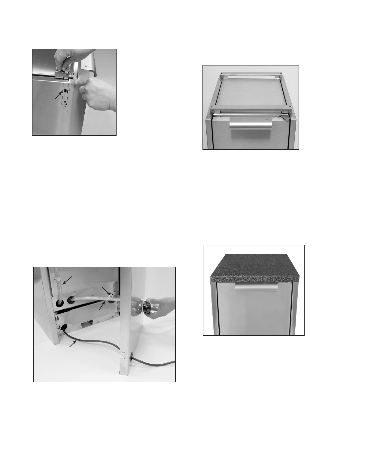
The 4 male catch clips are preinstalled in the back 9.
panel. See your Icemaker Use & Care Manual for
instructions on connecting to your potable water
supply and drain. Route the supply hose thru the
large opening in the back panel and connect to
the inlet on the back of the Icemaker. If you have
installed the optional drain pump (sold separately model # RF15I-P), feed the drain line thru this same
large opening. Feed the power cord thru the smaller
opening and install protective grommets on both
openings (Fig. 12).
Once you have tested the unit and veried there 10.
are no leaks, align the rear panel male clips to the
preinstalled female clips of the side panels, push at
the outer corners to engage clips. See Fig. 13 for
nal assembly. Do not bundle-up excess hose & cord
behind the panel.
Fig. 13
Solid Surface Installation – Required Accessory
(sold separately):
Solid Surface for Icemaker (WRT15I) ■
Locate holes on the solid surface and place onto 1.
the Icemaker so the holes align on the sides.
Check for proper t and alignment. Insert screws
(10-24 X 1-1/8) to anchor solid surface to risers. See
Fig. 14 for nal assembly.
Vent hose
Power cord
Water inlet
Drain hose
Fig. 12
Rear of Icemaker
shown with
optional drain
pump installed
Fig. 14
Final check to see that all spacing and gaps are even 2.
and level.
3
Page 4

Assembly Instructions for Modular
application (linked to a CAD cart):
Note: Installation of optional drain pump (sold
separately - model # RF15I-P) must be done
before installation of wrapper.
Remove (2) screws on front bottom grill cover from 1.
the Icemaker and set them aside (Fig. 01).
Remove (4) screws on back panel of Icemaker as 2.
shown (Fig. 02). (Retain screws for re-use.)
Install 2 Tinnerman U-Nuts on Icemaker Adapter (Fig. 3.
03) and attach to upper area of Icemaker as shown
(Fig. 04 and 05). Repeat for the bottom location.
Tighten all screws at this point.
With the grill head out of the cart, place the 4.
corresponding wrapper side panel against cart
side. Align the holes at the top front and rear side
corners and install hex bolts (1/4-20 X 1/2 HEX BLT)
and locking nuts (1/4-20 HEX NUT) provided with
hardware kit, using the second hole from the top on
the cart panel and top hole on the wrapper panel
(Fig. 15). Do not tighten at this point.
SIDE PANEL
CAD CART
When installing multiple units as a permanent b.
installation (such as an island) it is recommended
to remove the cart casters and install leveling
legs (sold separately - model # CAD-LVL).
Align the bottom front ange with the Icemaker (Fig. 3.
06 ). Slide the units together so the U-nut holes are
visible in the slotted holes of the upper and lower
rear anges of the side panel. Install machine screws
(10-24 X 3/8) into U-nuts as shown (Fig. 07 and 08).
Do not tighten at this point. Take care not to damage
anges on the female clips.
Level the legs on the Icemaker as described in 5a. 4.
Reinstall bottom front grill cover and screws. Leave
screws loose about 1/8 of an inch.
Note: If connecting Icemaker between carts,
repeat steps (4-6) for opposite side of
Icemaker, then proceed to step 9.
Place the other side panel on the unit by 5.
aligning bottom front ange with the Icemaker
(Fig. 06). Lift the rear of the side so the U-nut holes
are visible in the slotted holes of the upper and lower
rear anges of the side panel. Install machine screws
(10-24 X 3/8) into U-nuts as shown (Fig. 07 and 08).
Do not tighten at this point. Take care not to damage
anges on the female clips.
Place both top risers on top of unit as shown in 6.
(Fig. 09).
REAR VIEW
Fig. 15
Before connecting the two units, make sure that all 5.
of the height requirements are matched:
The Icemaker leveling legs can be adjusted a.
to match the cart assembly or your counter top.
Check the level on both units. The bottom front
corners will match and the front faces will be
ush (Fig. 16).
CAD CART
Front Faces
Flush
ICE MAKER
Using the machine screws provided (10-24 X 1-1/8) 7.
attach risers to side panels. Take note of alignment of
the holes on the riser and side panels (Fig. 10).
Make a nal adjustment to the Icemaker leveling 8.
legs so the side panels are level with the top unit,
and then tighten all screws, front and rear.
The 4 male catch clips are preinstalled in the back 9.
panel. See your Icemaker Use & Care Manual for
instructions on connecting to your potable water
supply and drain. Route the supply hose thru the
large opening in the back panel and connect to
the inlet on the back of the Icemaker. If you have
installed the optional drain pump (sold separately model # RF15I-P), feed the drain line thru this same
large opening. Feed the power cord thru the smaller
opening and install protective grommets on all
openings (Fig. 11).
Once you have tested the unit and veried there 10.
are no leaks, align the rear panel male clips to the
preinstalled female clips of the side panels, push at
the outer corners to engage clips. See Fig. 14 for nal
assembly. Do not bundle-up excess hose & cord
behind the panel.
Bottom front
corners
Fig. 16
Front Lower
Flange
See Solid Surface Installation (page 3).11.
The grill head(s) can now be installed in the grill cart, 12.
refer to instructions in Grill or Cart Manual.
4
Page 5

DIMENSIONS SHOWN ARE CRITICAL
25-1/2"
17-7/32"
R 1/4"
ALL TOP AND
4 X CORNERS
FRONT OF UNIT
REAR OF UNIT
1.300
21.652
1/2"
ALL WALLS
2.894
C
16.213
BOTH SIDES
2X
Ø
.50 X .150 DEEP
2X .18
BOTH SIDES
DETAIL C
SCALE 1 : 2
2X Ø.250
BOTH SIDES
NO EPOXY BUILD UP
ALL INSIDE CORNERS
*
*
*
*
*
*
For optional type and colors of the Solid Surface, contact your local manufacturer and provide drawing in Fig. 17.
Fig. 17
5
Page 6

NOTES
6
Page 7

NOTES
7
Page 8

Fisher & Paykel Appliances, Inc.
5900 Skylab Road, Huntington Beach, CA 92647
Customer Care: 888.281.5698 • Fax: 714.372.7003
www.dcsappliances.com
P/N 242828 RA 06/08
 Loading...