

Page 1
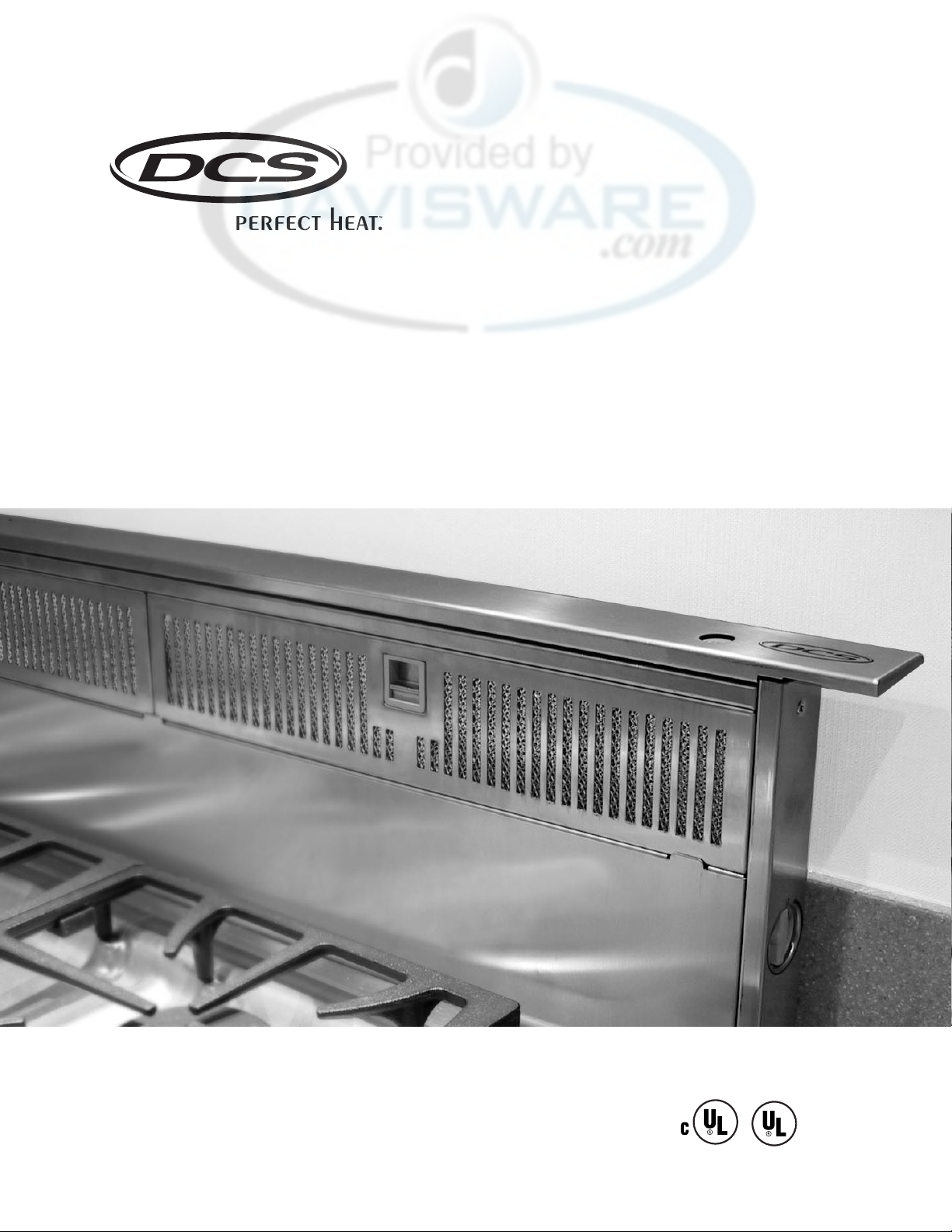
THE PROFESSIONAL DOWNDRAFT
Installation Guide
MODELS:
DD-36SS
Page 2
1
A MESSAGE TO OUR CUSTOMERS
Thank you for selecting this DCS Downdraft Vent System. Because of its unique features, we have developed
this Installation Guide. It contains valuable information on how to properly install your new Downdraft
Vent System for years of safe and enjoyable cooking.
For your convenience,product questions can be answered by a DCS Customer Service Representative by
phone: 1-888-281-5698,or Fax: 714-372-7004.
or by mail:
DCS
Attention: Customer Service
5800 Skylab Road,
Huntington Beach, CA 92647
WAR NING
TO REDUCE THE RISK OF A COOKTOP GREASE FIRE:
Never leave surface units unattended at high settings. Boilovers cause
smoking and greasy spillovers that may ignite. Heat oils slowly on low or
medium setting. Always turn the Downdraft “ON” when cooking at high heat
or when cooking flaming foods. Clean ventilating fans frequently. Grease
should not be allowed to accumulate on fan or filter. Use proper pan size.
Always use cookware appropriate for the size of the surface element.
WAR NI NG
TO REDUCE THE RISK OF INJURY TO PERSONS IN THE EVENT OF A COOK TOP
GREASE FIRE, OBSERVE THE FOLLOWING: SMOTHER FLAMES with a closefitting lid, cookie sheet, or metal tray,then turn off the burner. BE CAREFUL TO
PREVENT BURNS. If the flames do not go out immediately EVACUATE AND
CALL THE FIRE DEPARTMENT. NEVER PICK UP A FLAMING PAN - You may be
burned. DO NOT USE WATER, including wet dishcloths or towels - a violent
steam explosion will result. Use an extinguisher ONLY if:
1. You know you have a Class ABC extinguisher, and you already know how to
operate it.
2. The fire is small and contained in the area where it started.
3. The fire department is being called.
4. You can fight the fire with your back to an exit.
PLEASE RETAIN THIS MANUAL FOR FUTURE REFERENCE.
Page 3
2
TABLE OF CONTENTS
SAFETY PRACTICES & PRECAUTIONS ..............................................................................................................................3
PLANNING THE INSTALLATION...........................................................................................................................................4
SPECIFICATIONS .......................................................................................................................................................................5
INSTALLATION INSTRUCTIONS ....................................................................................................................................6-11
Tools Needed ............................................................................................................................................................6
Plan The Ductwork..................................................................................................................................................6
Plan And Make The Cutout..................................................................................................................................7
Installing The Downdraft Vent .....................................................................................................................8-11
WIRING DIAGRAM .................................................................................................................................................................12
HOW TO OBTAIN SERVICE ..................................................................................................................................................13
WAR RANT Y ...............................................................................................................................................................................14
Page 4
3
SAFETY PRACTICES & PRECAUTIONS
WAR NING:
ALL WALL AND FLOOR OPENINGS WHERE THE Downdraft IS INSTALLED MUST
BE SEALED.
Consult the cooktop installation instructions given by the manufacturer before making any cutouts.
MOBILE HOME INSTALLATION - The installation of this Downdraft must conform to the Manufactured
Home Construction and Safety Standards, Title 24 CFR, Part 3280 (formerly Federal Standard for
Mobile Home Construction and Safety,Title 24, HUD,Part 280). Four wire power supply must be used
and the appliance wiring must be revised. See Electrical Requirements (page 4).
Venting system MUST terminate outside the home.
DO NOT terminate the ductwork in an attic or other enclosed space.
DO NOT use 4" laundry-type wall caps.
Flexible-type ductwork is not recommended.
DO NOT obstruct the flow of combustion and ventilation air.
Failure to follow venting requirements may result in a fire.
Electrical ground is required on this downdraft ventilation system.
If cold water pipe is interrupted by plastic,non-metallic gaskets or other materials, DO NOT use
for grounding.
DO NOT ground to a gas pipe.
DO NOT have a fuse in the neutral or grounding circuit. A fuse in the neutral or grounding
circuit could result in electrical shock.
Check with a qualified electrician if you are in doubt as to whether the downdraft is properly
grounded.
Failure to follow electrical requirements may result in a fire.
WAR NI NG:
TO REDUCE THE RISK OF FIRE, ELECTRICAL SHOCK, OR INJURY TO PERSONS,
OBSERVE THE FOLLOWING:
Use this unit only in the manner intended by the manufacturer. If you have
any questions, contact the manufacturer. Before servicing or cleaning unit,
switch power off at service panel and lock the service disconnecting means
to prevent power from being switched on accidentally. When the service
disconnecting means cannot be locked,securely fasten a prominent warning
device, such as a tag, to the service panel. Installation Work And Electrical
Wiring Must Be Done By Qualified Person(s) In Accordance With All
Applicable Codes And Standards, Including Fire-Rated Construction.
Sufficient air is needed for proper combustion and exhausting of gases
through the flue (chimney) of fuel burning equipment to prevent
backdrafting. Follow the heating equipment manufacturer's guideline and
safety standards such as those published by the National Fire Protection
Association (NFPA), and the American Society for Heating, Refrigeration and
Air Conditioning Engineers (ASHRAE), and the local code authorities. When
cutting or drilling into wall or ceiling, do not damage electrical wiring and
other hidden utilities. Ducted fans must always be vented to the outdoors.
Page 5
4
PLANNING THE INSTALLATION
VENTING REQUIREMENTS
Determine which venting method is best for your application. Ductwork can extend either through
the wall or the roof. The length of the ductwork and the number of elbows should be kept to a mini-
mum to provide efficient performance. The size of the ductwork should be uniform. Do not install
two elbows together. Use duct tape to seal all joints in the ductwork system. Use caulking to seal exte-
rior wall or floor opening around the cap. Flexible ductwork is not recommended. If it is used, each
foot of flexible ductwork used is equivalent to two feet of straight metal ductwork when calculating
the duct run length. Thus, a flexible elbow equals two standard elbows. Make sure there is proper
clearance within the wall or floor for exhaust duct before making cutouts. Do not cut a joist or stud
unless absolutely necessary. If a joist or stud must be cut, then a supporting frame must be
constructed.
WAR NING:
To Re d u c e The Risk O f Fire,Use Only Metal Ductwork.
ELECTRICAL REQUIREMENTS
A 120 volt, 60 Hz AC-only electrical supply is required on a separate 15 amp circuit,fused on both
sides of the line. A time-delay fuse or circuit breaker is recommended. The fuse must be sized per
local codes in accordance with the electrical rating of this unit as specified on the serial/rating plate
located inside the unit near the field wiring compartment.
THIS UNIT MUST BE CONNECTED WITH COPPER WIRE ONLY. Wire sizes must conform to the requirements of the National Electrical Code,ANSI/NFPA 70 -latest edition,and all local codes and ordinances.
Wire size and connections must conform with the rating of the appliance. Copies of the standard listed
above can be obtained from:
National Fire Protection Association
Battery March Park
Quincy,Massachusetts 02269
This appliance should be connected directly to the fuse disconnect (or circuit breaker) through
flexible, armored or non-metallic sheathed copper cable. Allow some slack in the cable so the
appliance can be moved if servicing is ever necessary. A UL Listed, 1/2" conduit connector must be
provided at each end of the power supply cable (at the appliance and at the junction box). When
making the electrical connection, cut a 1 1/4" hole in the wall. A hole cut through wood must be
sanded until smooth. A hole through metal must have a grommet.
NOTE: SUITABLE FOR USE WITH SOLID STATE SPEED CONTROLS.
CAUTION:
For General Ventilating Use Only. Do Not Use To Exhaust Hazardous or
Explosive Materials and Vapors.
Page 6

5
SPECIFICATIONS
Fig. 01 Downdraft Dimensions
FIG.02 Ductwork Cutout Dimensions
8-1/4"
33"
36"
1-1/2"
3-1/4"
16"
x 10"
16"
23-9/16"
9-3/8"
4-1/8"
1/2"
min.
26-1/8"
2"
+
17-3/16"
3/8"
3-1/4"
4-1/8"
10"
4-1/8"
+
1/2"
min.
3/8"
+
1/2" min.
17-9/16"
Page 7

45° Elbow 5.0 feet
90° Elbow 7.0 feet
90° Flat Elbow 12.0 feet
Wall Cap 0.0 feet
6
INSTALLATION INSTRUCTIONS
TOOLS NEEDED FOR INSTALLATION PARTS SUPPLIED FOR INSTALLATION
Saber Saw or Jig Saw 6 Mounting Brackets
Drill 2 End Caps
1 1/4 Wood Drill Bit 16 Screws
Pliers 1 Backdraft Damper
Phillips Screwdriver
Flat Blade Screwdriver
Wire Stripper or Utility Knife
Metal Snips
Measuring Tape or Ruler
Level
Pencil
Caulking Gun
Duct Tape
PA RTS NEEDED FOR INSTALLATION
2 Conduit Connectors
Power Supply Cable
1 Wall or Roof Cap
All Metal Ductwork
PLAN THE DUCTWORK
The DCS 36”downdraft vent system can be ducted in four
different directions; down, left,right or back using a
3 1/4" X 10" rectangular vent. Fig. 03 illustrates venting
options. Fig.02 shows the ductwork cutout dimensions.
CALCULATE THE DUCT RUN LENGTH
The ductwork length should not exceed 35 equivalent
feet for 3 1/4" X 10" duct, or 60 equivalent feet for 9"
round duct. Calculate the length of the ductwork by
adding the equivalent feet listed in Fig. 04 for each piece
of duct in the complete system. An example is given in
Fig. 05. For best results, use no more than three 90°
elbows. Make sure that there is a minimum of 24" of
straight duct between elbows if more than one is used. Do not install two elbows together. Round
duct is recommended instead of rectangular duct especially if elbows are needed. Rectangular duct
should transition to round as soon as possible (6”round minimum).
9 Feet Straight Duct 9.0 feet
2 - 90° Elbows 14.0 feet
Wall Cap 0.0 feet
Total System 23.0 feet
FIG.03 Ducting
FIG.04
FIG.05
VENTING DOWN VENTING LEFT
VENTINGRIGHT VENTING
BACK
Page 8

7
PLAN AND MAKE THE CUTOUT
It is recommended that the installer draw the cooktop and downdraft cutouts on the countertop
before making any cutouts to avoid mistakes. Fig. 06 shows the cutout dimensions for DCS CT-365
and for all other cooktops see Fig. 06a (page 8). Fig. 07 shows the tolerances between the cooktop
and the downdraft. These tolerances must be observed for proper installation.
WAR NING:
When planning the cutout for the downdraft:
Draw both the cooktop and downdraft cutouts on the countertop before
making any cuts.
Check that there is enough room in the cabinet for both. Failure to follow
these warnings could result in damage to the countertop.
WAR NING:
These tolerances must be observed!
5" Min.
clearance
to combustible
surface
DCS CT-365 DROP-IN COOKTOP
CUT-OUT DIMENSIONS (W/DOWN DRAFT)
34-3/4" Width
19-3/4" Depth
33-1/2"
1/2" Min.
2-1/2"
INSTALLATION INSTRUCTIONS
Fig. 06
Page 9

8
INSTALLING DOWNDRAFT VENT
1) Remove the unit from the carton
and place on a flat surface for
assembly. Cover the surface to
prevent accidental damage.
Remove all downdraft parts
including the 6 mounting
brackets, 2 end caps, 16 screws,
literature package,and backdraft
damper.
2) Attach the overcounter support
arms to the left and right sides of
the downdraft body as indicated
in Fig. 08. Two short screws are
provided. Attach the end caps to
the left and right sides of the
downdraft over the overcounter
support arms. Attach the lower
support legs to left and right
sides of the downdraft into the
threaded slots on each side.
INSTALLATION INSTRUCTIONS
Fig. 06a
FIG.07
DROP-IN COOKTOP (MISC. BRAND)
CUT-OUT DIMENSIONS (W/DOWN DRAFT)
Rear of Downdraft Cutout
1/2" Min.
Rear Edge of Cooktop
1-3/4"
*
5" Min.
clearance
to combustible
surface
33-1/2"
* Measured from the rear edge of cooktop to rear of downdraft
cutout. It is recommended that the installer draw the cooktop
and downdraft cutouts on the countertop before making any
cutouts to avoid mistakes.
36 "
3/4"
25 "
CUTOUT DEPTH
COOKTOP
22-1/2"
24 "
V
E
N
T
1/4"
1/2" min.
3/4"
COOKTOP
1-7/8"
1/4"
FRONT
VENT
COUNT ERTOP
Page 10

9
INSTALLING DOWNDRAFT
(continued)
The lower support legs have
holes for mounting to the
cabinet floor and can be
installed on either side
depending upon the length
required. Determine if the
holes should be in the front or
on the sides.
3) Carefully insert the unit into
the cutout. Due to the size and
weight, two people are
recommended when lifting
this unit. Make sure that the
downdraft is fully seated in the
cutout and the support arms
rest firmly on the countertop.
4) Adjust the lower support legs
until both rest firmly on the
cabinet floor. Place a level
vertically on the front side of
the blower box to make sure
that the unit is level and not leaning to
the front or rear. Once the unit is properly
aligned,mark a starter hole on the cabinet
floor where the lower support legs will
attach to the cabinet floor.
5) Remove the unit from the cabinet. Drill
starter holes in the cabinet floor for the
leg screws.
6) DCS downdrafts are shipped from the
factory ready to vent in the down
position. If you need to vent back, left or
right, then the blower must be repositioned.
To vent t o the left or the right:
Four hex nuts attach the blower box to the
downdraft body. Remove all four nuts and
carefully remove the blower box. To vent left
or right, simply rotate the blower box 90° to
the left or right and re-assemble.
To vent to the rear:
Venting to the rear requires that the blower be
repositioned inside the blower box as
indicated in Fig. 09. The blower is attached to the blower box by 6 screws. Remove the blower from
the blower box. Note the position of the angle mounting rails on each side of the blower. To vent to
the rear,both mounting rails must be repositioned on the blower as illustrated in Fig.10. Attach the
mounting rails as indicated. Re-attach the blower to the blower box. Re-attach the blower box to
INSTALLATION INSTRUCTIONS
FIG.08
FIG.09
FIG.10
UNDER COUNTER
MOUNT BRACKETS
OVER COUNTER
SUPPORT ARMS
LOWER SUPPORT LEGS
end cap
Venting Left, Right or Down
Venting to the Rear
Page 11

10
INSTALLING DOWNDRAFT (continued)
the downdraft. The square metal frame must be attached to the mouth of the blower. The exhaust
knockout on the rear must be removed. A metal plate and two screws are supplied in the hardware
package to cover the unused exhaust exit.
CAUTION:
Make sure that the wiring cable connecting the blower to the field wiring
compartment remains securely attached under the two cable clamps.
7) Attach the Backdraft Damper.
8) Remove the field wiring compartment cover and determine which direction the wiring will run
from the appliance to the wiring box and remove the wiring knockout.
9) Insert the downdraft unit into the countertop cutout. Make sure that the unit is firmly placed at
the rear of the cutout. Fasten the legs to the cabinet floor using the two longer Phillips head
screws supplied in the hardware package.
WAR NI NG:
When attaching the Under Counter Mounting Brackets:
DO NOT drill into the countertop surface.
Check that the mounting screws are proper length and will not extend
through the countertop surface when tightened. Failure to follow these
warnings could result in damage to the countertop surface.
10) Attach the downdraft to the countertop using the undercounter mounting brackets (Fig. 08). This
system is designed to adjust to different countertop thicknesses. Using the small Phillips head
machine screws in the hardware package, attach one undercounter mounting bracket to the slot
on the upper right corner of the unit. Attach the other end of the bracket to the underside of the
countertop.
11) Thread the power supply cable through the wiring knockout into the field wiring compartment.
Connect the three white wires together with a twist-on wire connector. Connect the two black
wires with a twist-on wire
connector. Attach the Green (or
Green and Yellow) ground wire
to the eyelet with the green
grounding screw. Replace the
field wiring compartment cover.
12) Turn the power supply on. Push
and hold the Up/Down button
momentarily. The downdraft will
rise out of the countertop and
stop in the fully extended
position. Position the top strip
over the the top of the
downdraft, lining up the fixing
hooks and the hole for the push
button. Snap into place. Turn
the blower on. The blower
control switch is located on the
right hand side of the plenum as
indicated in Fig.11.
INSTALLATION INSTRUCTIONS
FIG.11
Up/Down
Button
Blower Control
Switch
Wiring
Box
Knock-out
Grounding
Screw
Wiring Box Cover
Page 12

11
INSTALLING DOWNDRAFT (continued)
13) Connect the ductwork to the Backdraft damper. Seal all joints with duct tape and vent to the
outside of the home.
14) Install the cooktop according to the cooktop manufacturer's instructions. Check to make sure
that the rear edge of the cooktop overlaps the front edge of the downdraft by 3/8".
IF THE BLOWER DOES NOT OPERATE:
1) Check that the circuit breaker is not tripped or the house fuse blown.
2) Check that the grease filters are properly installed. (See the section on Safety Microswitches
page 4 of Use and Care Guide).
3) Disconnect the power supply and check that the wiring connections have been made properly.
INSTALLATION INSTRUCTIONS
Page 13

12
WIRING DIAGRAM
GEAR
BLU
WHT
WHT
BLK
WHT
BLK
BLK
BLK
WIRING
BOX
LINE IN
120 VAC
60 Hz
GRN
WHT
SWITCH
DOWN N.C.
SWITCH
UP N.C.
BLK BLK
BLK BLK
BLK
BLK
BLK
WHT
SPEED
CONTROL
SWITCH
FAN N.O.
SWITCH
FILTER N.O.
N.O.
WHT
11 UF
PUSH
BUTTON
MOTOR
BLOWER
M
MOTOR
8/50K-A120
BLU
BLU
Page 14

13
SERVICE
HOW TO OBTAIN SERVICE:
Before you call for service:
1) Is the circuit breaker tripped or the fuse blown?
2) Is there a power outage in the area?
3) Are the grease filters properly installed?
For warranty service, contact DCS Customer Service at (888) 281-5698.
Before you call, please have the following information ready:
Model Number
Serial Number
Date of installation
A brief description of the problem
Your satisfaction is of the utmost importance to us. If a problem cannot be resolved to your satisfaction,
please write or fax us at:
Write:
DCS
Attention: Customer Service
5800 Skylab Road
Huntington Beach, CA 92647
Fax us at: (714) 372-7004
Page 15

14
WARRANT Y
LENGTH OF WARRANTY
One (1) Year Full parts and Labor Covers the entire product.
Five (5) Year Limited warranty covering the switches and motor.
DCS WILL PAY FOR
All repair labor and parts found to be defective due to materials or workmanship for one full year “IN
HOME” warranty during the first year of ownership. This does not apply if the unit was subjected to
other than normal household use. Service must be provided by Authorized Factory Agent during
normal working hours. No charges will be made for repair or replacement at the location of initial
installation or factory for parts returned pre-paid, through the dealer and claimed within the warranty
period, and found by DCS to be defective.
Replacement will be F.O.B.DCS, and DCS will not be liable for any transportation costs, labor costs,or
export duties. This warranty shall not apply,nor can we assume responsibility for damage that might
result from failure to follow manufactures instructions or local codes, where the appliance has been
tampered with or altered in anyway or which, in our judgement, has been subjected to misuse,
negligence, or accident. Implied warranty shall not extend beyond the duration of this written
warranty. This warranty is in lieu of all warranties expressed or implied and all other obligations or
liability in connection with the sale of this appliance.
DCS WILL NOT PAY FOR
Installation or start-up.
Shipping damage.
Service by an unauthorized agency.
Damage or repairs due to service by an unauthorized agency or the use of unauthorized parts.
Service during other than normal working hours.
Improper installation, such as improper hook-up, etc.
Service visits to teach you how to use the appliance; correct the installation; reset circuit
breakers or replace home fuses.
Cleaning of filters and outer panels.
Repairs due to other than normal household use.
Damage caused from accident, abuse, alteration, misuse, incorrect installation or installation
not in accordance with local codes.
Units installed in non-residential application such as day care centers, bed and breakfast
centers, churches, nursing homes, restaurants, hotels, schools, etc.
This warranty applies to appliances used in residential applications; it does not cover their use in
commercial situations. This warranty is for products purchased and retained in the 50 states of the
U.S.A., the District of Columbia and Canada. This warranty applies even if you should move during the
warranty period. Should the appliance be sold by the original purchaser during the warranty period,
the new owner continues to be protected until the expiration date of the original purchaser’s warranty
period. This warranty gives you specific legal rights. You may also have other rights which vary from
state to state.
 Loading...