

Page 1
Dynamic Cooking S ystems, Inc.
ISLAND VENT HOOD
Care and Use Installation Instructions
Models:
■
DCS-IVH-48
■
DCS-IVH-36
Page 2
1
Thank you for selecting this DCS Professional Island Vent Hood. Because of this appliance’s unique features we
have developed this Installation and Use Guide. It contains valuable information on how to properly operate and
maintain your new appliance for years of safe and enjoyable use.
To help serve you better, please fill out and return the Ownership Registration Card and keep this Guide handy,
as it will help answer questions that may arise as you use your new vent hood.
For your convenience, product questions can be answered by a
DCS Technical Support Representative by phone:
1-888-281-5698 or Fax: 714-372-7003
or by mail:
DCS
Attention Customer Service,
5800 Skylab Road, Huntington Beach, CA 92647
Before proceeding with installation, please read this installation guide and observe all safety precautions
and warnings.
NOTE: Installation of this DCS Island Vent Hood must comply with all local codes.
IMPORTANT: Save these instructions for the Local Electrical Inspector’s use.
INSTALLER: Please leave these instructions with the unit for the owner.
OWNER: Please retain these instructions for future reference.
Mes sag e To Our Customers
Page 3
2
Tab le of Contents
IMPORTANT SAFETY INSTRUCTIONS . . . . . . . . . . . . . . . . . . . . . . . . . . . . . . . . . . . . . . . . . . . . . . . . .3
FEATURES . . . . . . . . . . . . . . . . . . . . . . . . . . . . . . . . . . . . . . . . . . . . . . . . . . . . . . . . . . . . . . . . . . . . . . . . . . . . . . . . . . .4
PLANNING THE INSTALLATION . . . . . . . . . . . . . . . . . . . . . . . . . . . . . . . . . . . . . . . . . . . . . . . . . . . . . . . . . . . . . .5
SPECIFICATIONS. . . . . . . . . . . . . . . . . . . . . . . . . . . . . . . . . . . . . . . . . . . . . . . . . . . . . . . . . . . . . . . . . . . . . . . . . . .6
SITE PREPARATION AND INSTALLATION GUIDELINES . . . . . . . . . . . . . . . . . . . . . . . . . . . .7
SOFFIT INSTALLATION . . . . . . . . . . . . . . . . . . . . . . . . . . . . . . . . . . . . . . . . . . . . . . . . . . . . . . . . . . . . . . .8-10
DUCTING INFORMATION . . . . . . . . . . . . . . . . . . . . . . . . . . . . . . . . . . . . . . . . . . . . . . . . . . . . . . . . . . . . . .11
CARE AND USE . . . . . . . . . . . . . . . . . . . . . . . . . . . . . . . . . . . . . . . . . . . . . . . . . . . . . . . . . . . . . . . . . . . . . . . .12-13
WIRING DIAGRAM . . . . . . . . . . . . . . . . . . . . . . . . . . . . . . . . . . . . . . . . . . . . . . . . . . . . . . . . . . . . . . . . . . . . . . .14
WARRANTY INFORMATION . . . . . . . . . . . . . . . . . . . . . . . . . . . . . . . . . . . . . . . . . . . . . . . . . . . . . . . . . . . .15
SERVICE . . . . . . . . . . . . . . . . . . . . . . . . . . . . . . . . . . . . . . . . . . . . . . . . . . . . . . . . . . . . . . . . . . . . . . . . . . . . . . . . . . . .16
Page 4
3
Important Safety Instructions
WARNING:To reduce the risk of a range top grease fire:
A) Never leave surface units unattended at high settings. Boilovers cause smoking and greasy
spillovers that may ignite. Heat oil slowly on low or medium settings.
B) Always turn hood “ON” when cooking at high heat or when cooking flaming foods.
C) Clean ventilating fans frequently. Grease should not be allowed to accumulate on fan or filter.
D) Use proper pan size. Always use cookware appropriate for the size of the surface element.
Make-Up air may be necessary to prevent air flowing down chimney, unsealed door, window, or fireplace
opening.
WARNING:To reduce the risk of fire, electrical shock, or injury to persons, observe the following
guidelines.
A) Installation and electrical wiring must be performed by qualified personnel in accordance
with all applicable codes & standards, including fire-rated construction.
B) To Prevent Backdrafting, sufficient air is needed to maintain proper combustion and safe
exhausting of gases through the flue (chimney) of fuel burning equipment. Follow the cooking
equipment manufacturers guideline and safety standards such as those published by the
National Fire Protection Association (NFPA) and the American Society for Heating,
Refrigeration and Air Conditioning Engineers (ASHRAE), and the local code authorities.
C) Use caution when cutting or drilling into walls or ceilings as not to damage electrical wiring
and other hidden utilities.
CAUTION: To Reduce the risk of fire and to properly exhaust air, be sure to duct air to outside. -do
not vent exhaust air into spaces within walls or ceiling, nor into attics, crawl spaces, or
garages.
NOTE: Unit MUST be vented to the outside of the building.
IMPORTANT: Refer to ducting information supplied on Pg. 11
Page 5
4
Features
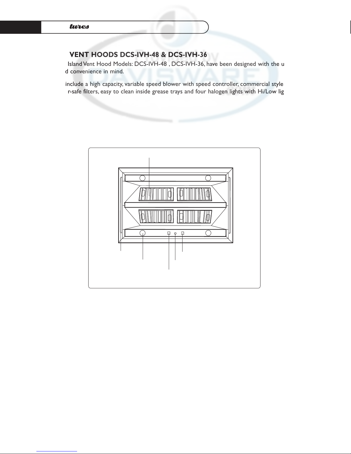
ISLAND VENT HOODS DCS-IVH-48 & DCS-IVH-36
The DCS Island Vent Hood Models: DCS-IVH-48 , DCS-IVH-36, have been designed with the ultimate in
household convenience in mind.
Features include a high capacity, variable speed blower with speed controller, commercial style
dishwasher-safe filters, easy to clean inside grease trays and four halogen lights with Hi/Low light switch.
(4)
halogen
lights
light on/off switch
blower variable speed control
blower on/off switch
removable washable filters
hanger rods
Page 6
5
Planning the Installation
BACKDRAFT DAMPER
We recommend that a backdraft damper be used in all Vent Hood installations. Cold weather installations necessitate the use of a backdraft damper to minimize the flow of cold air into the room.A
non-metallic thermal break should also be installed to minimize conduction of outside temperatures
through the ductwork. Locate the thermal break as close as possible to where the ducting enters the
heated portion of the house.
PLANNING THE INSTALLATION
Before beginning installation of the Island Vent Hood and Ventilator, PLAN OUT the entire installation
procedure beforehand, considering the following areas:
• HOOD SIZE & LOCATION- (The hood should be as wide or wider than the cooking
appliance with the hood being centered on the appliance.Vertically, the bottom of the hood
should be between 30”-36” above the appliance cooking surface.)
• DUCTING- (ducting transitions, air must flow to outside, use of Backdraft damper...etc.)
• ELECTRICAL REQUIREMENTS- (120 Volts, 60 Hz, 15 AMP Service, Local Codes...etc.)
• ADEQUATE MOUNTING SURFACES- (To support the weight of the vent hoods, location of
ceiling studs, additional support for safe ceiling mounting...etc.)
HANDLING NOTE: This Hood has been inspected prior to shipping to be free of defects. due to the
weight of the Island Vent Hood and Ventilator; and to prevent scratching or
denting the unit, we recommend the use of two installers to move, place, and
secure the Vent Hood to avoid personal injury or damage to the Hood.
Page 7

6
Specifications
PRODUCT AND VENTING SPECIFICATIONS
Refer to venting specifications below when ordering the duct transition to 10” Ø for 36” Island Vent
Hood.
See Page 11 for
Ducting Information.
30"
12"
TOP VIEW of DCS-IVH-48
18"
12"
TOP VIEW of DCS-IVH-36
venting specs 7" Ø
venting specs 4"x18" rectangular
16"
52 5/8"
30"
16"
FRONT VIEW
SIDE VIEW
34 5/8"
12"
12"
34 5/8"
DCS-IVH-48
DCS-IVH-48
DCS-IVH-36
DCS-IVH-36
VENT HOOD DIMENSIONS
Page 8

7
Site Preparation and I nstallation G uidelines
SITE PREPARATION
You will need to create a secure soffit structure to mount the Island Vent Hood to the ceiling.We
suggest using 1 1/2” by 3 1/2“ wood cut to fit the installation as shown in the following pages.The soffit
mounting to the top of the Island Vent Hood will be 10 7/8“ in length for the DCS-IVH-48 and 10 3/4“
for the DCS-IVH-36.These dimensions allow room for a 1/2 drywall duct cover. Do not deviate from
these dimensions when choosing a duct cover as the soffit structure must align with the mounting
holes on the Island Vent Hood.You are limited to a maximum of 1/2 inch on all sides.
NOTE: You will need to determine which type of duct cover will be used before installation and leave
enough space around the soffit for a flush mount between the duct cover material and the top
of the Island Vent Hood.
CAUTION: When installing the ISLAND VENT HOOD directly to the ceiling, adequate structural
supports are critical to secure the unit.The Island Vent Hood is heavy, weighing 128 LBS for
the DCS-IVH-48 and 94 LBS for the DCS-IVH-36.
NOTE: The soffit height will vary according to the ceiling height.
GENERAL INSTALLATION GUIDELINES:
1) Determine the location for installation.
2) Determine the centerline of the installation.
3) If drywall is installed, cut away enough drywall to expose 2 ceiling joist (1 on each side of the
Hood center line)
4) Create your soffit structure according to ceiling height and attach soffit plates for DCS-IVH-36
or soffit brackets for DCS-IVH-48 with screws to sides (see the following pages for soffits and
construction).
5) Attach soffit structure to existing ceiling joist.
6) Secure soffit with soffit braces according to model type (see diagrams page 8-10).
7) Attach Island Vent Hood to soffit with the six 2 inch mounting screws provided.
FINISHING THE INSTALLATION:
Once the Island Vent Hood has been mounted in place it will be necessary to install the electrical
service. All electrical work should be done by a qualified electrician and must conform to all local
standards. Refer to the wiring diagram on Pg. 14 for proper hook-up and grounding.
NOTE: Black=live, White=neutral, Green=ground
Complete the installation by making ductwork connections, testing unit functions, and installing
& finishing drywall.
Page 9

8
Soffit Installation
SOFFIT FOR DCS-IVH-36 ISLAND VENT HOOD
The dimensions given are for a 1/2 inch drywall.
1) Create a soffit structure and attach the soffit brackets as in figure 1. Refer to the installation
guidelines on Page 7.
2) Attach the soffit support bars as shown in figure 2.
3) After securing the soffit structure adequately to the ceiling joist, attach the Island Vent Hood
with the mounting screws provided, figure 3.
Refer to page 7 on finishing the installation.
36" ISLAND VENT HOOD SOFFIT MOUNTING
6 Mounting Screws
SOFFIT BRACKETS
SCREWED TO BOTH SIDES
OF SOFFIT STRUCTURE
SCREW SUPPORT BARS
ON BOTH SIDES AS SHOWN
CREATE YOUR
SOFFIT STRUCTURE
ACCORDING TO THE
CEILING HEIGHT
THEN ATTACH IT
TO THE CEILING JOIST.
Create your Soffit Structures
first and attach Soffit Brackets
to each side with screws provided
FIG.3
FIG.1
SUPPORT
BARS
SOFFIT ASSEMBLY
FOR 36" ISLAND VENT HOOD
10 3/4 "
HEIGHT WILL
VARY
ACCORDING
TO CEILING
HEIGHT
16 3/4 "
The dimensions given
are for a 1/2 " drywall.
FIG.2
Page 10

9
Soffit Installation
SOFFIT FOR DCS-IVH-48 ISLAND VENT HOOD
The dimensions given are for a 1/2 inch drywall duct cover.
1) Create a soffit structure and attach the soffit brackets as illustrated in figure 1. Refer to the
installation guidelines on Page 7.
2) Attach the soffit support bars as shown in figure 4.
3) After adequately securing the soffit structure to
the ceiling joist, attach the Island Vent Hood with
the 6 mounting screws provided, figures 5 and 6
show the location of the mounting screws.
Figure 5 gives soffit dimensions allowing for a 1/2 inch
duct cover.
ATTA CH SOFFIT
BRACKETS
ON 4 CORNERS
OF THE
SOFFIT STRUCTURE
2 SUPPORT
BARS
SOFFIT ASSEMBLY
FOR DCS-IVH-48
10
7
/
8
"
HEIGHT WILL
VARY
ACCORDING
TO CEILING
HEIGHT
28
7
/
8
"
4 SOFFIT
BRACKETS
The dimensions given are for a 1/2 " drywall.
FIG.4
28 7/8"
10 7/8"
TOP VIEW of DCS-IVH-48
SIDE VIEW for DCS-IVH-48 SOFFIT STRUCTURE
1 1/2" x 31/2" Soffit
3 1/2"centerline
to centerline measurement
from screw to screw
Wood Structure
1
1/2" x 31/2" Soffit
(4) soffit
brackets
The dimensions given are for a 1/2 " drywall.
FIG.5B
Page 11

10
Soffit Installation
DIAGRAMS FOR DCS-IVH-48 ISLAND VENT HOOD
The dimensions given are for a 1/2 inch drywall duct cover.
Figure 6 below illustrates a finished soffit structure for the DCS-IVH-48
Refer to page 7 on finishing the installation.
counter top level
FRONT VIEW of DCS-IVH-48
30" Min.
to cooking surface
Support Bars
Ceiling
Floor
Typical 96"
Ceiling Shown
Duct Cover
NOTE: Duct
Cover height
will vary according
to ceiling height
these must be
custom built.
6 Mounting Screws
Solid Soffit Structure
mounted to ceiling joices
FIG.6B
Page 12

11
Ducting I nformation
GENERAL
When planning the path for ducting to the outside, keep in mind the following guidelines:
• Minimize use of elbows and transitions in ductwork as to maximize air flow to outside of
building.An efficient airflow path contributes to the overall efficiency of the Vent Hood.
• DCS recommends the use of “smooth wall” ducting, not flexible ductwork.
• Transitions are required from rectangular to round ducting.
(see transitions as shown below)
• Duct tape may be used at ducting joints.
DCS-IVH-48 REQUIREMENTS
• DCS recommends the use of 10” round ducting which provides 78.6 In.2of surface area.
• See Duct Accessories below on for ratio to 10” transition.
• Alternate duct sizes in rectangular style may be used. If a rectangular duct style is used, the duct
must equal at least 78.6 In.
2
for best results. (Example- 3 1/4”x 24” duct = 78 In.2)
• Maintain consistent ducting square area as to avoid reduced air flow. [ie.- With a ivh-48 Hood,
connecting a 4”x13” (52 In.
2
) to a 10”round (78.6 In.2) is not recommended]
DCS-IVH-36 REQUIREMENTS
• DCS recommends the use of 7” round ducting which provides 34.7 In.2of surface area.
• Alternate duct sizes in rectangular style may be used. If a rectangular duct style is used, the duct
must equal at least 34.7 In.
2
for best results
DUCT ACCESSORIES
• Wall Caps and Roof Caps must have free open area equal to duct size diameter.
• Note that a Sealed Back Draft Damper may reduce air delivery.
• Transition for right, left or rear air discharge also available.
10"
10
1
/2"
4
5
/8"
Vertical Duct Transition for 48" Island Vent Hood
18
5
/8"
11"
Page 13

12
Care And Use
CONTROLS
We recommend you turn your hood on before you begin cooking to establish fresh airflow.After you
have finished cooking, let the blower run for a few minutes to clear the air and help keep the kitchen
fresh and clean.
BLOWER
The Blower is operated with 2 controls.The switch adjacent to the speed control turns the blower
on/off, while the speed control adjusts the blower speed.Turn the speed knob clockwise to increase
and counterclockwise to decrease the blower speed.
HOOD LIGHTING
A single switch controls the 4 halogen lights.The switch controls the brightness of the lights with
Hi/Off/Low. Use only 50w Max. Halogen Narrow Flood replacement bulbs.
CAUTION: Halogen lamps are constructed of a glass bulb with a pressurized internal filament tube
that operates at high temperatures and could be discharged into the fixture enclosure
and/or surrounding environment, thereby creating a risk of personal injury of fire.When
replacing the bulb, let the bulb cool, and assure that power to light has been turned off.
Never allow a hot bulb to come into contact with water.
Do Not Touch the Hood Light Bulbs when they are in use.They may be hot enough to cause injury.
Blower
Blower Variable Speed Control
Hood Lights
Halogen Light Bulb
Page 14

13
Care And Use
CLEANING THE EXTERIOR STAINLESS STEEL FINISH:
When cool the appliance can be cleaned with hot soapy water, rinsed, dried and buffed to a shine with
a soft, heavy pile cloth.Always try this first, as it is the mildest form of cleaning.
1. Some brands of cleaners are harsher than others. Read their instructions.Try on a small
inconspicuous area first.
2. To avoid marring the surface always rub metal finishes in the direction of the polish lines.The
cleaner will be more effective when used in the direction of the polish lines.
3. Use only clean sponges, soft cloths, paper towels, plastic non-metal soap pads for cleaning or
scouring, use only soap pads with soap still in them, a dry pad can scratch the surface.
4. Be sure to rinse thoroughly and to wipe dry to avoid water marks.
FILTERS AND GREASE TRAYS
Filters should be cleaned frequently in a detergent solution and are dishwasher safe. Empty grease
collection tray(s) regularly.
Unplug the Blower Motor before cleaning Ventilator.
• Remove filters to access blower motor plug.Vacuum blower
to clean.
• Do not immerse in water.
• Do not allow and excessive accumulation of grease.
• Use a mild detergent when cleaning.
• Do not use harsh abrasives, steel wool pads, or abrasive
cloths.
CLEANING THE GREASE TRAY
Remove filter(s) by gently pulling up and out.The grease trays can
easily be reached once the filters are removed. Grease collection
trays are easily accessible at the center beneath the filter. See
illustration below for location.
Location of grease trays
DCS-IVH-36
DCS-IVH-48
FILTERS
GREASE TRAY
Page 15

14
Wiring D iagram
DCS-IVH-48 & DCS-IVH-36 ISLAND VENT HOOD
Page 16

15
Warranty
LENGTH OF WARRANTY
One (1) Year Full parts and labor covers the entire product
Five (5) Years Limited switches and motor
DCS WILL COVER:
All repair labor and parts found to be defective due to materials or workmanship for one full year from
date of purchase. Service must be provided by an Authorized Factory Service Agent during normal
working hours.
DCS WILL NOT COVER:
• Installation or start-up
• General maintenance
• Shipping damage
• Service by an unauthorized agency
• Damage or repairs due to service by an unauthorized agency or the use of unauthorized parts.
• Service during other than normal working hours
• Improper installation, such as improper hook-up, etc.
• Service visit to teach you how to use the appliance; correct the installation; reset circuit breakers
or replace home fuses
• Repairs due to other than normal household use.
•Damage caused from accident, abuse, alteration, misuse, incorrect installation or installation not
in accordance with local codes
• Units installed in non-residential application such as day care centers, bed and breakfast centers,
churches, nursing homes, restaurants, hotels, schools, etc.
This warranty applies to vent hoods used in residential applications; it does not cover their use in
commercial situations.
This warranty is for products purchased and retained in the 50 states of the U.S.A., the District of
Columbia and Canada.This warranty applies even if you should move during the warranty period.
Should the appliance be sold by the original purchaser during the warranty period, the new owner
continues to be protected until the expiration date of the original purchaser’s warranty period.
This warranty gives you specific legal rights.You may also have other rights which vary from state to
state.
Page 17

16
Service
HOW TO OBTAIN SERVICE:
For warranty service, contact DCS Customer Service at (888) 281-5698.
Before you call, please have the following information ready:
• Model Number
• Serial Number
• Date of installation
• A brief description of the problem
Your satisfaction is of the utmost importance to us. If a problem cannot be resolved to your
satisfaction, please write or fax us at:
Write:
DCS
Attention: Consumer Relations
5800 Skylab Road
Huntington Beach, CA 92647
Fax us at: (714) 372-7003
 Loading...