

Page 1
THE PROFESSIONAL
36/48” BGB GRILL
Use and Care Guide
MODELS:
BGB36-BQAR
BGB48-BQAR
BGB48-BQR
Page 2

Page 3
A MESSAGE TO OUR CUSTOMERS
Thank you for selecting this DCS Professional “BGB” Series Grill. Because of these appliances’ unique features we
have developed this Use and Care Guide. It contains valuable information on how to properly install, operate and
maintain your new appliance for years of safe and enjoyable cooking.
To help serve you better, please fill out and submit your Product Registration by visiting our website at
www.dcsappliances.com and selecting “Customer Care” on the home page and then select “Product Registration”.
In addition, keep this guide handy, as it will help answer questions that may arise as you use your new appliance.
For your convenience, product questions can be answered by a DCS Customer Care Representative at
1-888-936-7872, or email: customer.care@fisherpaykel.com.
NOTE: Please write the Model, Code, and Serial Numbers on this page for reference (can be found on the inside,
right side panel behind the drip pan handle. See page 17.)
MODEL NUMBER CODE SERIAL NUMBER
NOTE: Inspect the product to verify that there is no shipping damage. If any damage is detected, call the shipper
and initiate a damage claim. DCS by Fisher & Paykel is not responsible for shipping damage.
DO NOT discard any packing material (box, pallet, straps) until the unit has been inspected.
WARNING!
Do not try lighting this appliance without reading the “Lighting Instructions” section of this manual.
Improper installation, adjustment, alteration, service or maintenance can cause property damage,
injury or death. Read the installation, operating and maintenance instructions thoroughly before
use, installing or servicing this equipment. This outdoor cooking gas appliance is not intended to be
installed in or on recreational vehicles , boats or in a non-ventilated room. For outdoor use only.
WARNING
1
. Do Not store or use gasoline or any other flammable vapors and liquids in the vicinity of
this or any other appliance.
2.
An LP cylinder not connected for use shall not be stored in the vicinity of this or any other
appliance.
DANGER
What To Do If You Smell Gas:
1.
Shut off gas to the appliance.
2.
Extinguish any open flames.
3.
Open lid.
4. If odor continues, keep away from the appliance and immediately call your gas supplier or
your fire department.
PLEASE RETAIN THIS MANUAL FOR FUTURE REFERENCE.
1
Page 4

TABLE OF CONTENTS
SAFETY PRACTICES & PRECAUTIONS 35
GRILL MODELS 6
INSTALLATION
Locating Grill / Built-in Clearances 7-9
Built-in Construction Details 10-11
Gas Hook-up 12-15
Leak Testing 16
Burner Adjustment 17
Radiant Assembly 18
Installer Checklist 19
USING THE GRILL
Lighting Instructions 20
Grilling 21-22
USING THE SMOKER SYSTEM 23
USING THE ROTISSERIE 2427
CARE & MAINTENANCE 2830
TROUBLESHOOTING 31
SERVICE 32
WARRANTY 3334
2
Page 5
SAFETY PRACTICES & PRECAUTIONS
IMPORTANT SAFETY NOTICE!
Certain Liquid Propane dealers may fill liquid propane cylinders for use in the grill beyond cylinder filling capacity.
This “Overfilling” may create a dangerous condition.
“Overfilled” tanks can build up excess pressure. As a safety device, the tank pressure relief valve will vent
propane gas vapor to relieve this excess pressure. This vapor is combustible and therefore can be ignited. To
reduce this danger, you should take the following safety precautions:
1.
When you have your tank filled, be sure you tell the supplier to fill it to no more than 3/4 (75%) of its total
capacity.
2
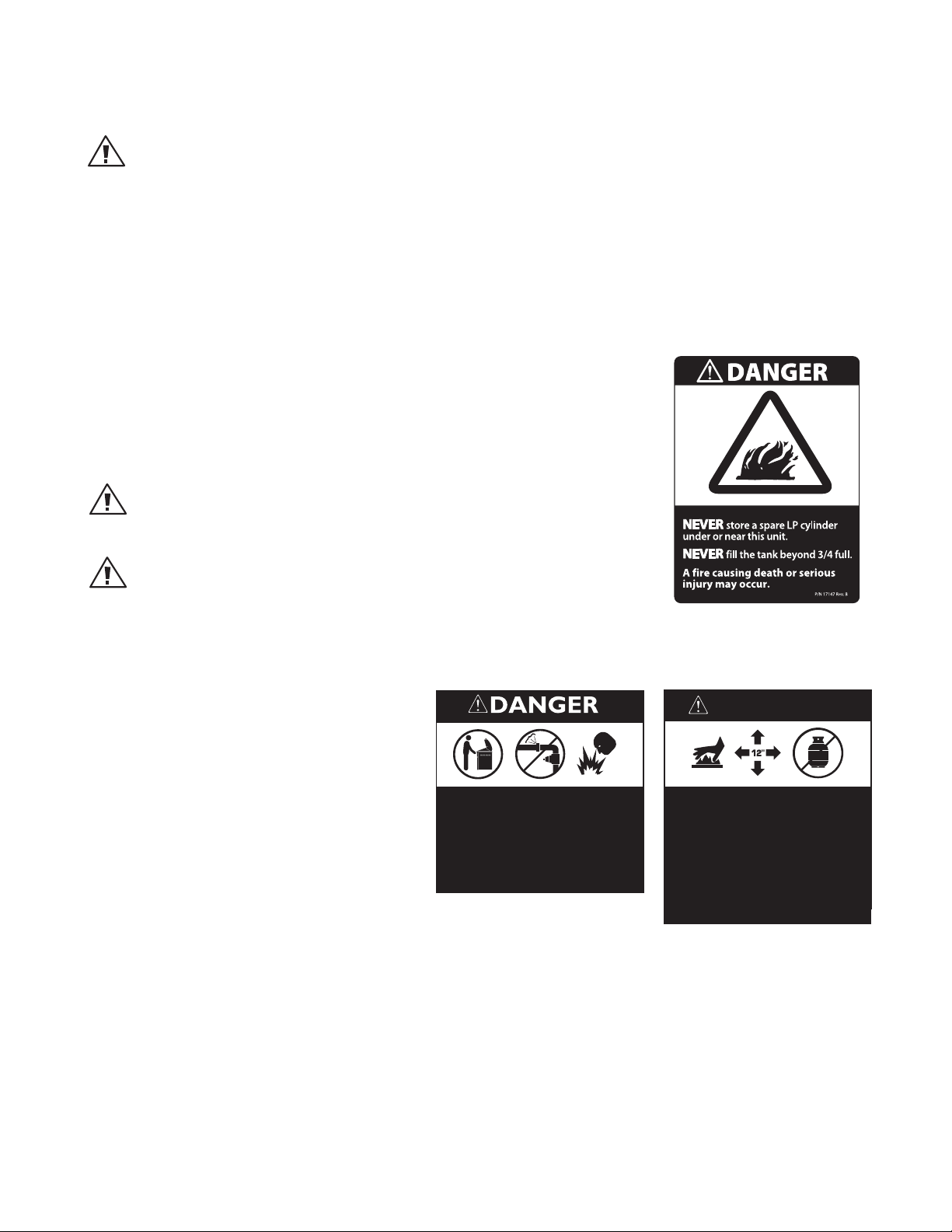
. If you own or use a spare tank, or have a disconnected tank, you should NEVER
store it near or under the grill/cart unit or heat box, or near any other ignition or
heat source. A metallic sticker with this warning is provided with the grill to remind you, your family and all others who may use your BBQ grill of these safety
precautions. Install this sticker close to your barbeque grill.
3. Do not store a full tank in direct sunlight.
WARNING!
Do not try lighting this appliance without reading the “LIGHTING INSTRUCTIONS”
section of this manual. This grill is for outdoor use only.
WARNING!
Push and hold the igniter button, turn the selected burner knob to “SEAR”. If
burner does not light in 4 to 5 seconds turn knob “OFF” and wait 5 minutes before
trying again for any accumulated gas to dissipate.
■
Begin by insuring proper installation and
servicing. Follow the installation instructions within this manual. Have your grill
installed by a qualified installer. Have the
installer show you where the gas supply
shut-off valve is located so that you know
where and how to shut off the gas to the
grill. If you smell gas, your installer has not
done a proper job of checking for leaks. If
the connections are not perfectly sealed,
you can have a small leak and therefore
a faint gas smell. Finding a leak is not a
“do-it-yourself ” procedure. Some leaks can
only be found with the burner control in the
“ON” position and this must be done by a
qualified technician.
• Always follow lighting instructions.
• Lid must be opened before lighting
the grill.
• Check for gas leaks before lighting.
• Never lean over an open grill when
lighting. Serious burns may result.
Sticker
WARNING
• Hot surfaces surrounding grill
grates could cause serious burns.
• Always leave at least 12" clearance
to combustibles around the grill.
• Never store a spare LP cylinder
under or near this unit.
• Never fill the tank beyond 3/4 full. A
fire causing death or serious injury
may occur.
■
Children should not be left alone or unattended in an area where the grill is being used. Never allow them to sit,
stand or play on or around the grill at any time. When in use, portions of the grill get hot enough to cause severe
burns.
■
Do not store items of interest to children around or below the grill, in the cart or masonry enclosure. Never allow
children to crawl inside a cart or enclosure.
■
Never attach or disconnect an LP cylinder, or move or alter gas fittings when the grill is in operation or is hot.
■
Clean and perform general maintenance on the grill twice a year. Watch for corrosion, cracks, or insect activity.
Check the regulator, hoses, burner ports, air shutter, and venturi/valve section carefully. Always turn off gas at
the source (tank or supply line) prior to inspecting parts.
3
Page 6
SAFETY PRACTICES & PRECAUTIONS
■
After a period of storage or non-use (such as over the winter), the gas grill should be checked for gas leaks, dete-
rioration, proper assembly, and burner obstructions before using.
■
Never let clothing, pot holders or other flammable materials come in contact with or get too close to any grate,
burner or hot surface until it has cooled. Fabric may ignite and result in personal injury.
■
Do not heat unopened food containers as a build-up of pressure may cause the container to burst.
■
Always use a covered hand when opening the grill lid and only do so slowly to allow heat and steam to escape.
■
Never lean over an open grill. When lighting a burner, always pay close attention to what you are doing. Be cer-
tain you are pushing the ignition button when you attempt to light the grill.
■
After lighting burners, make sure burners are operating normally (see page 17).
■
When using the grill, do not touch the grill burner, grate, or immediate surrounding area as these areas become
extremely hot and could cause burns.
■
Grease is flammable. Let hot grease cool before attempting to handle it. Avoid letting grease deposits collect in
the drip pan. Clean often.
■
Do not use aluminum foil to line drip pans or grill grates or radiants. This can severely upset combustion air flow
or trap excessive heat in the control area. The result of this can be melted knobs or damaged ignition components.
■
Do not operate with a damaged cord or plug.
For personal safety, wear proper apparel. Loose fitting garments or sleeves should never be worn while using
this appliance. Some synthetic fabrics are highly flammable and should not be worn while cooking. Only certain
types of glass, heat-proof glass ceramic, earthenware, or other glazed utensils are suitable for grill use. Use of
these types of materials may break with sudden temperature changes. Use only on low or medium heat settings
according to the manufacturer’s directions.
WARNING!
Spiders and insects can nest in the grill burners , causing gas not to flow through the burner. The gas will flow from
the front of the burner into the control panel. This is a very dangerous condition which can cause a fire to occur
behind the valve panel, thereby damaging the grill components and making it unsafe to operate.
WARNING!
Keep the area surrounding the grill free from combustible materials, trash, or combustible fluids and vapors such as
gasoline or charcoal lighter fluid. Do not obstruct the flow of combustion and ventilation air.
WARNING!
Never use the grill in windy conditions. If located in a consistently windy area (oceanfront, mountaintop, etc.) a wind
break will be required. Always adhere to the specified clearances listed.
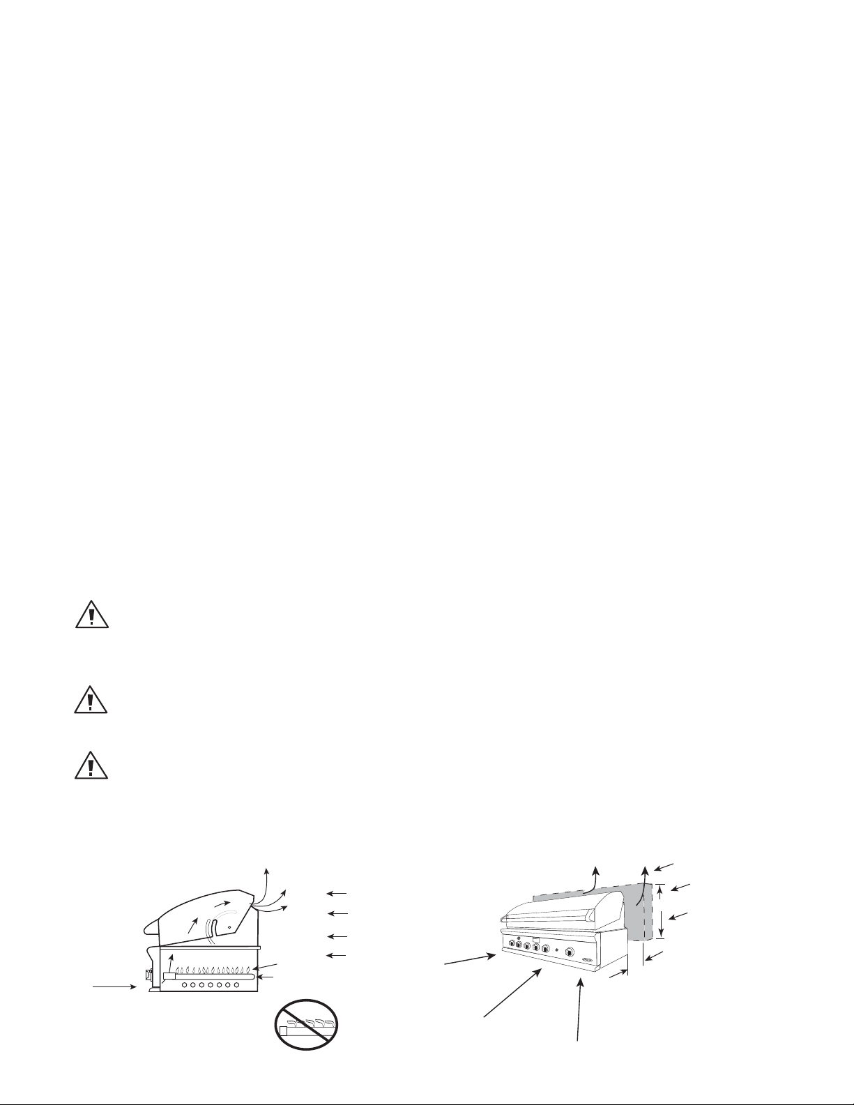
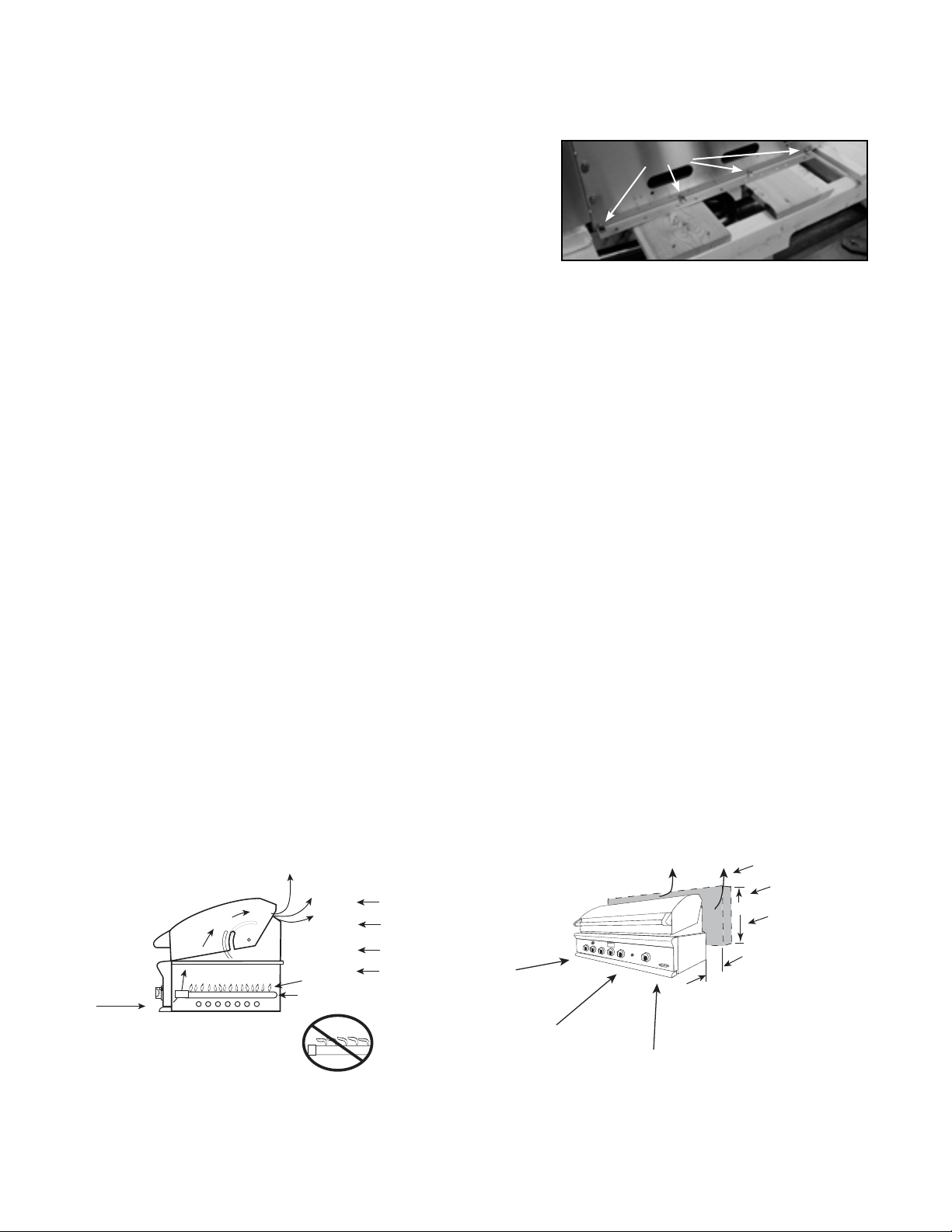
GRILL PLACEMENT
PREFERRED
AIR FLOW
EXHAUST
GRILL EXHAUST
FLAME
BURNER
FLAME LIFT
Wind hitting the
grill while in use,
especially winds
blowing into or
across this hood
gap, can cause
poor performance
and in some cases
can cause the
control panel to
get dangerously
hot.
WIND
PRIMARY
INTAKE
AIR FLOW
EXHAUST VENT FLOW
WIND SCREEN
3”
min.
WIND
WIND
15” min.
If wind is an
issue, a wind
screen should
be added. The
wind screen
should be
higher than
the top of the
opening in the
back of the
grill and
minimum of 3”
clearance
from the back
of the grill for
the lid .
4
Page 7

SAFETY PRACTICES & PRECAUTIONS
■
When using the side burners always use flat bottomed pans which are large enough to cover the side burner.
Adjust the flame so that it heats only the bottom of the pan to avoid ignition of clothing. Position handles inward
away from open edges of the unit to avoid burns associated with unintentional spillovers. Hold the handle of the
pan to prevent movement of it when turning or stirring food. For proper lighting and performance of the burners
keep the ports clean. It is necessary to clean periodically for optimum performance.
■
Clean the grill with caution. Avoid steam burns; do not use a wet sponge or cloth to clean the grill while it is hot.
Some cleaners produce noxious fumes or can ignite if applied to a hot surface.
■
Be sure all grill controls are turned off and the grill is cool before using any type of aerosol cleaner on or around
the grill. The chemical that produces the spraying action could, in the presence of heat, ignite or cause metal parts
to corrode.
■
Do not use the grill for cooking excessively fatty meats or products which promote flare-ups.
■
Never grill without the drip pan and grease tray in place and pushed all the way to the back of the grill. Without it
hot grease could leak downward and produce a fire or explosion hazard.
■
Do not operate the grill under un protected combustible construction. Use only in well ventilated areas. Do not
use in buildings, garages, sheds, breezeway, covered structure or other such enclosed areas. This unit is for outdoor use only.
■
If a cart unit is stored indoors, ensure that it is cool, fold the side shelf down, then push, never pull, the grill and
never push or pull on the side shelves. If LP, the cylinder must be unhooked and the LP cylinder stored outside in a
well ventilated area, out of reach of children.
■
Never use the grill in a windy area.
■
Do not use charcoal or lighter fluid in the outdoor grill.
■
Keep any electrical supply cord, or the rotisserie motor cord away from the heated areas of the grill and water
(pools, fountains, puddles).
■
Never use a dented or rusty LP tank. Keep the ventilation openings of the cylinder enclosure free and clear from
debris.
■
Use only dry potholders; moist or damp potholders on hot surfaces may cause burns from steam. Do not use a
towel or bulky cloth in place of potholders. Do not let potholders touch hot portions of the grill or burner grate.
■
Have an ABC rated Fire Extinguisher accessible – never attempt to extinguish a grease fire with water or other liq-
uids.
■
To avoid burns when cooking, use long handled BBQ tools.
■
Do not move the appliance during its use.
■
This unit is for outdoor use only! Do not operate in enclosed areas. This could result in carbon monoxide build-up
which would result in injury or death.
■
When using a grill, be sure that all parts of the unit are firmly in place and that the grill is stable (can’t be tipped
over).
■
To put out flare-ups, adjust the controls to lower the temperature
■
CALIFORNIA PROPOSITION 65-WARNING: The Burning of gas cooking fuel generates some by-products which are
on the list of substances which are known by the State of California to cause cancer or reproductive harm. California law requires businesses to warn customers of potential exposure to such substances. To minimize exposure to
these substances, always operate this unit according to the Use and Care Guide, ensuring you provide good ventilation when cooking with gas.
■
This outdoor cooking gas appliance is not intended to be installed in or on recreational vehicles, trailers and/or
boats.
Note:
This product must be installed by a licensed plumber or gas fitter when installed within the Commonwealth of
Massachusetts.
5
Page 8
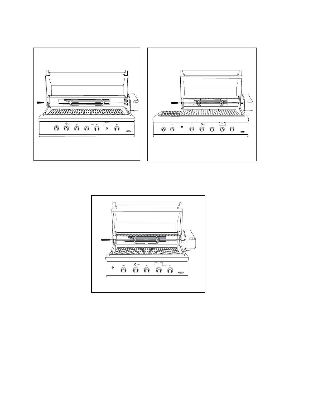
GRILL MODELS
IGNITION
BGB48BQAR
IGNITION
BGB48BQR
BGB36BQAR
6
Page 9
INSTALLATION
LOCATING GRILL/BUILTIN CLEARANCES
Important!
Shipping Brackets
Before installation, remove shipping brackets from the grill. To
do so, loosen the 4 screws on the bottom sides of the grill which
hold the brackets to the grill. Slide the shipping brackets off and
retighten the screws.
LOCATION:
When determining a suitable location take into account concerns
FIG. 01
such as exposure to wind, proximity to traffic paths and keeping
any gas or electrical supply lines as short as possible and away from heat sources. Locate the grill only in a well
ventilated area. Do not build the grill under overhead unprotected combustible construction. Never locate the
grill in a building, garage, breezeway, shed or other such enclosed areas. During heavy use, the grill will produce
a lot of heat and smoke. Ensure there is adequate area for it to dissipate.
If locating the grill in a windy area, try to locate the grill so the prevailing wind will blow air at the front of the
grill as shown in Fig. 02. This will assist the grill in venting hot air thru the back of the grill. In addition, this will
help keep any smoke from blowing at someone who is cooking on the grill. If you have to locate the grill in a
windy area where the prevailing wind is at the rear of the grill, a windbreak must be installed. The windbreak
should be made such that it will block wind from entering the exhaust vent in the rear of the unit as shown in Fig.
02.
As high-performance gas appliance, your grill requires significant amounts of air to support the combustion
process. Your grill is designed to take air in through the valve panel area, and send the exhaust products out
through the exhaust gap at the rear of the hood. Using your grill in windy conditions can disrupt the proper flow
of air though your grill, leading to reduced performance, or in certain severe cases, causing heat buildup in the
valve panel area. This can lead to problems such as having the knobs melt, or burn hazards when the valve panel
surfaces become too hot to touch.
During high wind conditions, it is best if you don’t use your grill. If you live in an area that is subject to frequent
high winds, or a steady directional wind, then the installation of a suitable windbreak may be advised. If you have
a grilling cart, it is best to position the unit so the prevailing wind blows into the valve panel, thus supporting the
proper airflow. Winds hitting the back of the grill directly are the most likely to cause problems, although wind
blowing along the exhaust gap in the rear can also be problematic.
Please note that damage to your grill resulting from use in windy conditions, such as melted knobs or igniter
wires, or valve panel discoloration from heat build-up, are excluded from warranty coverage.
GRILL PLACEMENT
EXHAUST VENT FLOW
WIND SCREEN
3”
min.
WIND
WIND
15” min.
If wind is an
issue, a wind
screen should
be added. The
wind screen
should be
higher than
the top of the
opening in the
back of the
grill and
minimum of 3”
clearance
from the back
of the grill for
the lid .
PREFERRED
AIR FLOW
EXHAUST
GRILL EXHAUST
FLAME
BURNER
FLAME LIFT
Wind hitting the
grill while in use,
especially winds
blowing into or
across this hood
gap, can cause
poor performance
and in some cases
can cause the
control panel to
get dangerously
hot.
FIG. 02
WIND
PRIMARY
INTAKE
AIR FLOW
Important!
Gas fittings, regulator, and installer supplied shut-off valves must be easily accessible.
7
Page 10
INSTALLATION
LOCATING GRILL/BUILTIN CLEARANCES
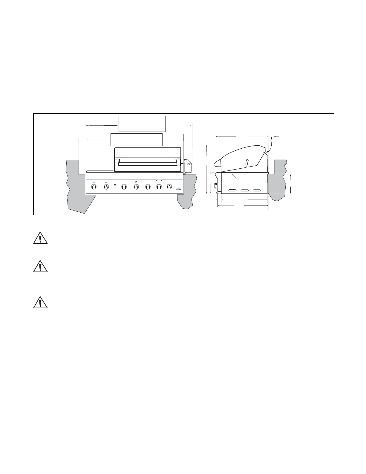
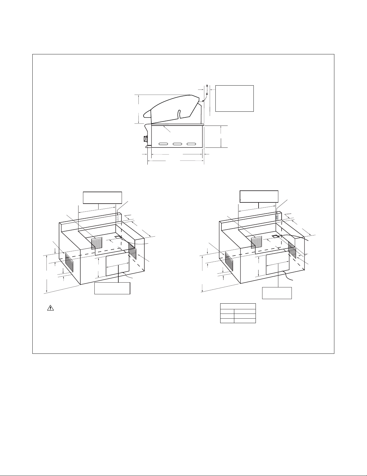
Clearances to Non-Combustible Construction*:
A minimum of 3” clearance from the back of the grill to non-combustible construction is required for the purpose
of allowing the lid to open fully. It is desirable to allow at least 6” rear and side clearance to non-combustible
construction above the cooking surface for counter space. If you’ll be using the rotisserie option, the space is essential for motor and skewer clearance. The grill can be placed directly adjacent to non-combustible construction
below the cooking surface. (Fig. 03)
Clearances to Non-Combustible Construction*
48 BQAR = 53-1/4"
48 BQR = 53-7/16"
36 BQAR = 41-5/8"
(with rotisserie motor mounted)
3"
48" Models = 47-7/8"
36" Models = 35-7/8"
(without rotisserie motor mounted)
rotisserie
motor
24-1/4"
26-1/2"
grill
exhaust
3" (to non-combustible
construction / minimum
lid clearance)
10-1/2"
2"
FIG. 03
Bottom of
support flange
22"
25-1/2"
10 "
WARNING!
Failure to maintain required clearances creates a fire hazard that may result in property damage or serious personal
injury.
WARNING!
The BGB Grill is designed to function in an open area. Recommended minimum clearances should be maintained
to all surfaces (combustible and noncombustible) for optimum performance. Noncombustible material within the
minimum clearance area could result in discoloration or deterioration.
WARNING!
If a noncombustible material such as stucco is covering a combustible material such as wood, the minimum clearance distance needs to be held to the wood. The presence of a noncombustible material inside the clearance zone
does not eliminate the minimum clearance zone to combustible material.
* DEFINITION OF NONCOMBUSTIBLE MATERIAL - Material which is not capable of being ignited and burned, such as
materials consisting entirely of, or a combination of, steel, iron, brick tile, concrete, slate, and plaster.
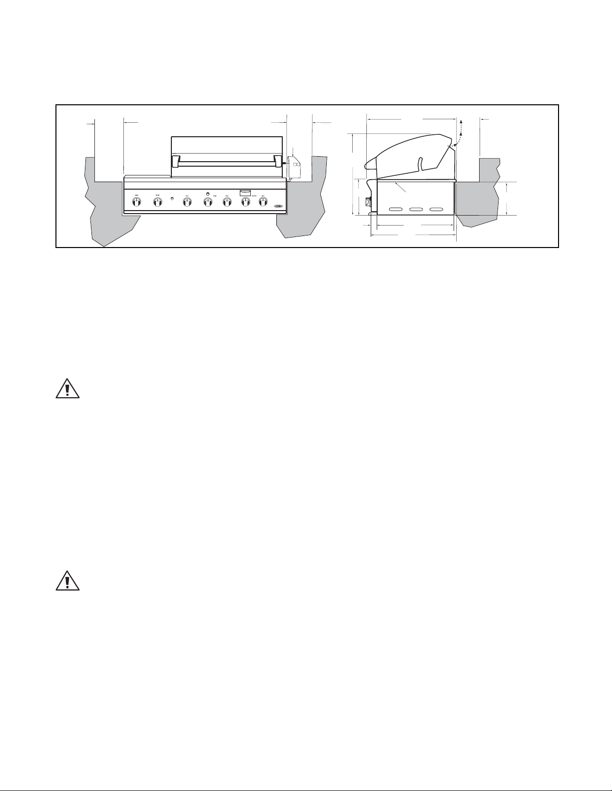
Clearances to Combustible Construction**:
Minimum of 12” from the sides and rear of grill must be maintained to adjacent vertical combustible construction, above the counter top level. You should take in account that there is a large volume of heat, and smoke will
exhaust from the rear of the grill. This may discolor or damage unprotected areas (Fig. 04). Do not install under
unprotected combustible construction without using a fire safe ventilation system.
A 12” minimum clearance must be maintained under the counter top to combustible construction. The clearance
can be modified by a use of an insulated jacket.
8
Page 11
INSTALLATION
LOCATING GRILL/BUILTIN CLEARANCES
Clearances to Combustible Construction**
12" min.
12" min.
rotisserie
motor
24-1/4"
26-1/2"
grill
exhaust
12" min. (to combustible
construction)
10-1/2"
2"
FIG. 04
Bottom of
support flange
22"
25-1/2"
10 "
** DEFINITION OF COMBUSTIBLE MATERIAL - Any materials of a building structure or decorative structure made
of wood, compressed paper, plant fibers, vinyl/plastic or other materials that are capable of transferring heat or
being ignited and burned. Such material shall be considered combustible even though flame-proofed, fire-retardant treated, or painted surface or plastered.
Important!
It is required that a minimum of (3) 10 sq. inches of ventilation opening be provided for both the left and right
sides, as well as the back of enclosure (Fig. 06 and 07), in order to safely dissipate unburned gas vapors in the
event of a gas supply leak.
WARNING!
Note specific built-in enclosure ventilation requirements. See text and Fig. 06.
GENERAL
The grill is designed for easy placement into built-in masonry enclosures. For non-combustible applications the
grill drops into the opening shown in Fig. 05 and hangs from its side flanges. A deck is not required to support it
from the bottom. When using the insulated jacket in a combustible enclosure application, see the bottom of
Fig. 05. The insulation jacket assembly must be supported from the bottom by a ledge on each side and back or a
solid deck.
A carpenter’s “spirit level” should be used to assure that the unit is level both front-to-back and side-to-side. If it
is not level, burner combustion may be erratic or the unit may not function efficiently for grease flow. If the floor
is uneven or has a decided slope, re-leveling may be required after each moving of a freestanding unit.
INSULATED JACKET:
WARNING!
Installing this product into a combustible enclosure without an insulated jacket could result in fire, property damage
and personal injury.
If the grill is to be placed into a combustible enclosure, an approved insulated jacket is necessary. Insulated jackets are available from your dealer. Use only the DCS insulated jacket which has specifically been designed and
tested for this purpose. Review the detail drawing shown (Fig. 05) and take into account the provisions shown for
gas line hook-up clearance in the right rear corner. It is required that ventilation holes are provided in the enclosure to eliminate the potential build-up of gas in the event of a gas leak. The supporting ledges or deck must be
level and flat and strong enough to support the grill and insulated jacket. The counter should also be level.
9
Page 12
INSTALLATION
BUILTIN CONSTRUCTION DETAILS
13-3/4"
Bottom of
support flange
grill
exhaust
3" (to non-combustible
construction / minimum
lid clearance)
12" (to combustible
construction)
10"
2"
Standard layout for non-combustible enclosure:
NOTE: If using a backguard
48" Models = 45-3/4"
36" Models = 34-1/2"
2
Min. ventilation
10 in.
on the back side
10 in.2 min.
ventilation
left hand
side
10-1/8"
35-1/2"
Max.
1" Min.
WARNING!
If installing the grill into a non-combustible enclosure, all combustible
construction must still be outside the 12 inch clearance zone. If your
island is made of stucco over the top of wooden studs, the wood can not
be inside the 12 inch clearance zone to combustible, even though the
stucco is what is touching the grill area.
18-1/2"
20"
48" Models = 46"
36" Models = 34"
apron or rear wall, locate
electrical service on the
right hand side for rotisserie
motor connection
3" Min. for Lid
Clearance
22-3/4"
opening for access doors/
drawers
(see Fig. 06 & 07 for
ordering information)
4" x 4" opening
for gas supply
line
2
min.
10 in.
ventilation
on the right
hand side
22"
25-1/2"
1-1/2"
Layout for insulated jacket only - combustible enclosure:
NOTE: If using a backguard
apron or rear wall, locate
electrical service on the
right hand side for rotisserie
motor connection
3" Min. for Lid
Clearance
23-3/4"
4" x 4" opening
for gas supply
line
3"
10 in.
ventilation
on the right
hand side
opening for access
doors/drawers
(see Fig. 06 & 07 for
ordering information)
10 in.
on the back side
10 in.2 min.
ventilation
left hand
side
11-1/8"
35-1/2"
Max.
2
min. ventilation
1" Min.
48" Models = 51-5/8"
36" Models = 40-1/2"
INSULATED JACKET
Size Part No.
36 70167
48 70172
18-1/2"
20"
48" Models = 46"
36" Models = 34"
2
min.
FIG. 05
10
Page 13
INSTALLATION
BUILTIN CONSTRUCTION DETAILS
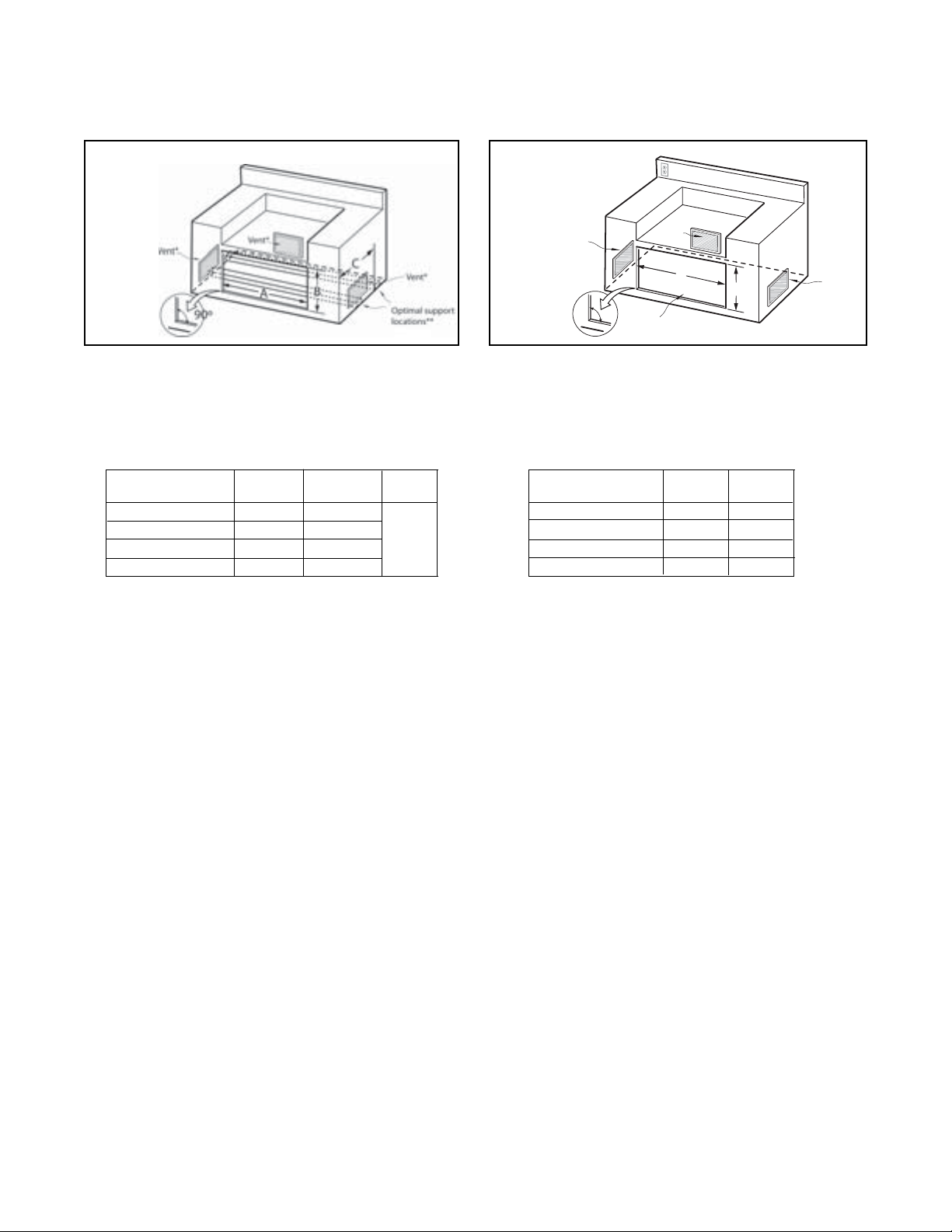
Access Drawers
Cutout dimensions
FIG. 06
º
NOTE: The cutout of each corner should be 90
drawers to fit properly.
* Island installation to use minimum of 3 vents, 10 square inches per vent (typical).
** For proper support and drawer operation, insure that support boards are
installed per Installation Guide instructions.
MODEL NUMBER A B C
+0,1/8 +1/8,0
ADR48 46” 20”
ADR36 34” 20”
ADR30 28” 20”
ADR24 22” 20”
angle in order for the access
24-1/2”
(Min,
All
Models)
Access Doors Cutout dimensions
Vent*
NOTE: The cutout of each corner should be 90
for the access doors to fit properly.
* Island installation to use minimum of 3 vents, 10 square
inches per vent (typical).
MODEL NUMBER A B
+0,1/8 +1/8,0
Vent*
A
90º
Cutout for Access Doors
FIG. 07
B
º
angle in order
ADN 20x48 46” 20”
ADN 20x36 34” 20”
ADN 20x30 28” 20”
ADN 20x24 22” 20”
Vent*
11
Page 14
INSTALLATION
GAS HOOKUP
GAS REQUIREMENTS
Verify the type of gas supply to be used, either natural or LP, and make sure the marking on the appliance rating
plate agrees with that of the supply. The rating plate is located underneath the unit bottom. Never connect an
unregulated gas line to the appliance. You must use the gas regulator provided with the unit, even if the supply is
controlled.
An installer-supplied gas shut-off valve must be installed in an easily accessible location. All installer supplied
parts must conform to local codes, or in the absence of local codes, with the National Electrical Code, ANSI/NFPA
70 or the Canadian Electrical Code, CSA C22.1, and the National Fuel Gas Code, ANSI Z223.1 or CAN/CGA-B149.1
Natural Gas Installation Code or CAN/CGA-B149.2 Propane Installation Code.
All pipe sealants must be an ap proved type and resistant to the actions of LP gases. Never use pipe sealant on
flare fittings. All gas connections should be made by a qualified technician and in accordance with local codes
and ordinances. In the absence of local codes, the installation must comply with the National Fuel Gas Code ANSI
Z223.1. Gas conversion kits are available from the factory. When ordering gas conversion kits, have the model
number, and the type of gas (natural or LP) from your grill.
TOTAL GAS CONSUMPTION OF THE GRILL WITH ALL BURNERS ON HI:
BGB48-BQR - 126,500 Btu/hr BGB48-BQAR - 121,500 Btu/hr BGB36-BQAR - 92,500 Btu/hr
The appliance and its individual shut-off valve must be disconnected from the gas supply piping system during
any pressure testing of that system at test pressures in excess of 1/2 PSIG (3.5 kPa.) The appliance must be isolated from the gas supply piping system by closing its individual manual shut-off valve during any pressure testing
of the gas supply piping system at test pressures equal to or less than 1/2 PSIG (3.5 kPa.). The installation of this
appliance must conform with local codes or, in the absence of local codes, with the National Fuel Gas Code, ANSI
Z223.1. Installation in Can ada must be in accordance with the Standard Can1-b149.1 and/or .2 (installation code
for gas burning appliances and equipment) and local codes.
NATURAL GAS HOOK UP: THIS TYPE OF CON
NECTION SHOULD BE PERFORMED BY A CERTIFIED OR
LICENSED TECHNICIAN ONLY.
Connection: 1/2” NPT male with 3/8” flare adapter. Operating pressure: 4.0” W.C. Supply pressure: 5” to 14” wa-
ter column. If in excess of 14” W.C., a step down regulator
is required. Check with your local gas utility company or
local codes for instructions on installing gas supply lines.
Be sure to check on type and size of run, and how deep to
bury the line. If the gas line is too small, the grill will not
function properly. Any joint sealant used must be an approved type and be resistive to the actions of LP gases.
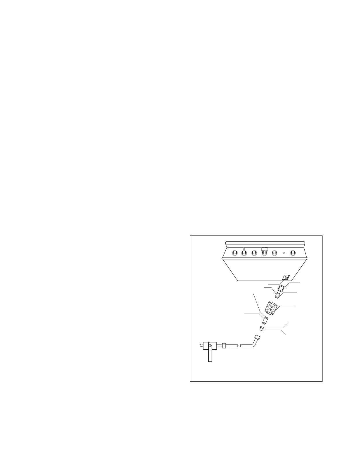
TO HOOKUP THE FITTINGS SUPPLIED WITH
THE GRILL:
Assemble as shown (Fig. 08). Use threading compound
on male threads only. Do not use threading compound
on the male end of the 1/2 NPT to 3/8 flare adapter. Use
a second pipe wrench to hold the grill inlet pipe to avoid
shifting any internal gas lines of the grill. Ensure that the
regulator arrow points in the direction of gas flow towards
the unit, away from the supply. Do not forget to place the
installer-supplied gas valve in an accessible location.
1/2” NPT x 5.0"
Nipple
Installer supplied shut-off
valve must be easily
accessible*
*Installation must conform with
local codes or with the National
Fuel Gas Code ANSI Z223.1 or
the CAN/CGA-B149.2 Propane
Installation Code
Bottom of unit
Threading compound
must be resistant to LP gas
FIG. 08 Natural Gas
Coupling
1/2” NPT x
2.0”
NIpple
Regulator
4.0" W.C.
Adapter 1/2” NPT
to 3/8” flare fitting
Do not put threading
compound on these
threads
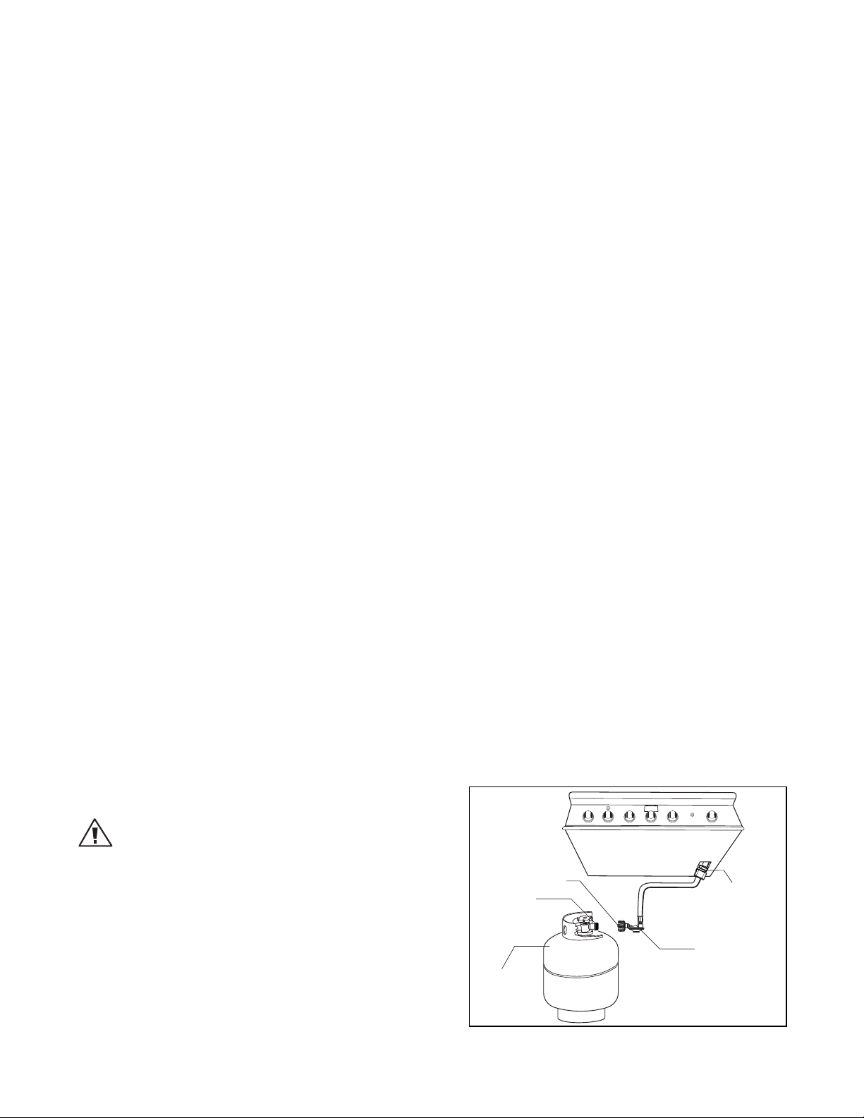
LP GAS HOOK UP TYPE 1 OR QCC1 REGULATOR:
Grills orificed for use with LP gas come equipped with a high capacity hose/regulator assem bly for connection to
a standard 20 lb. LP cylinder (Type 1). The LP tank is not included.
12
Page 15
INSTALLATION
GAS HOOKUP
Connection: 1/2” NPT male with a 3/8” Flare adapter (included). LP Hose with a quick disconnect and fittings are
included. Operating pressure: 11.0” W.C.
CAUTION!
Before connecting LP tank to regulator, check that all grill burners and side burners, smokers, and rotisserie valves
are in the OFF position and open grill lid.
To connect the LP regulator/hose assembly to the tank/valve assembly, first make sure the main valve on the tank
is completely closed. Although the flow of gas is stopped when the Type 1 system is disconnected as part of of
its safety feature, you should always turn off the LP tank main valve (Fig. 09) after each use and during transport
of the tank or unit. Insert the regulator inlet into the tank valve and turn to the black coupler clockwise until the
coupler tightens up. Do not overtighten the coupler. Turn the main tank valve on and turn the burner control
valves on the unit to the “HI” position for about 20 seconds to allow the air in the system to purge, turn valves off
and wait 5 minutes before attempting to light the burners.
To disconnect the coupler, first make sure the main tank valve is turned off. Grasp the coupler and turn counter
clockwise. The inlet will then disengage. Remove the inlet from the tank valve opening if it has not already done
so when it disengaged. Your local LP filling station should be equipped with the proper equipment to fill your
tank.
LP TANK REQUIREMENTS:
A dented or rusty LP tank may be hazardous and should be checked by your LP supplier. The cylinder that is
used must have a collar to protect the cylinder valve. Never use a cylinder with a damaged valve. Always check
for leaks after every LP tank change. The LP gas cylinder must be constructed and marked in accordance with the
specifications for LP gas cylinders of the U.S. Department of Transportation (DOT or CAN/CSA-B339) and designed for use with a Type 1 system only. Do not change the regulator/hose assembly from that supplied with the
unit or attempt to use a Type 1 equipped regulator/hose assembly with a standard 510 POL tank/valve assembly.
The cylinder must be provided with a shut-off valve terminating in an LP gas supply cylinder valve outlet specified, as applicable, for connection Type 1. If the appliance is stored indoors, the cylinder must be disconnected
and removed from the appliance. Cylinders must be stored outdoors in a well-ventilated area out of the reach
of children.
Note:
When an LP unit is being directly connected to an LP house system, you must follow the natural gas hook up guidelines.
The installer must provide the proper gas regulator to reduce the gas flow to 11” W.C.
Note:
The Grill comes with the LP Regulator/Hose assembly installed at the factory. The assembly, along with the entire Grill
system, is leak tested. Do not remove the Regulator/Hose
assembly from the Grill during installation.
WARNING :
1. Do not remove the Grill from the pallet until you are
ready to install.
2. Do not place the Grill directly on the ground or any other
flat surface without support. This will prevent damaging
the regulator/hose assembly by the weight of the grill.
3. Check the hose, regulator and connectors for damage.
Look for cracks, abrasions, brittleness, holes, dents and
nicks.
4. Do not attempt to remove, repair, or replace the Regulator/Hose assembly by yourself. It must be done by a
qualified licensed technician only.
13
Type 1 Regulator
Main Tank Valve
20 lb. LP Tank
Bottom of unit
*Installation must conform with
local codes or with the National
Fuel Gas Code ANSI Z223.1 or the
CAN/CGA-B149.2 Propane
Installation Code
FIG. 09 LP Gas
º
Elbow 45
1/2” female
NPT x 3/8” male flare
(installed on the unit)
LP Regulator hose
assembly 11" W.C.
Page 16
INSTALLATION
GAS HOOKUP
LP TANK RESTRAINT FOR BUILTIN INSTALLATION
If the grill is to be installed in a Built-in application, then the grill must be installed in accordance with the
Built–in installation guidelines.
If you intend to operate your Built-in grill on LP gas utilizing a 20 lb Type 1 cylinder, then the Built-in LP tank
restraint must be installed prior to initial use of the grill. If you do not have one please contact DCS Customer Care
at (888) 936-7872 for information on obtaining one.
The following steps will illustrate how to properly locate and install the LP tank restraint within the Built-in enclosure.
NOTE:
The grill comes with the LP Regulator/Hose assembly installed at the factory. The assembly, along with the entire grill
system, is leak tested.
Do not remove the Regulator/Hose assembly from the grill during installation.
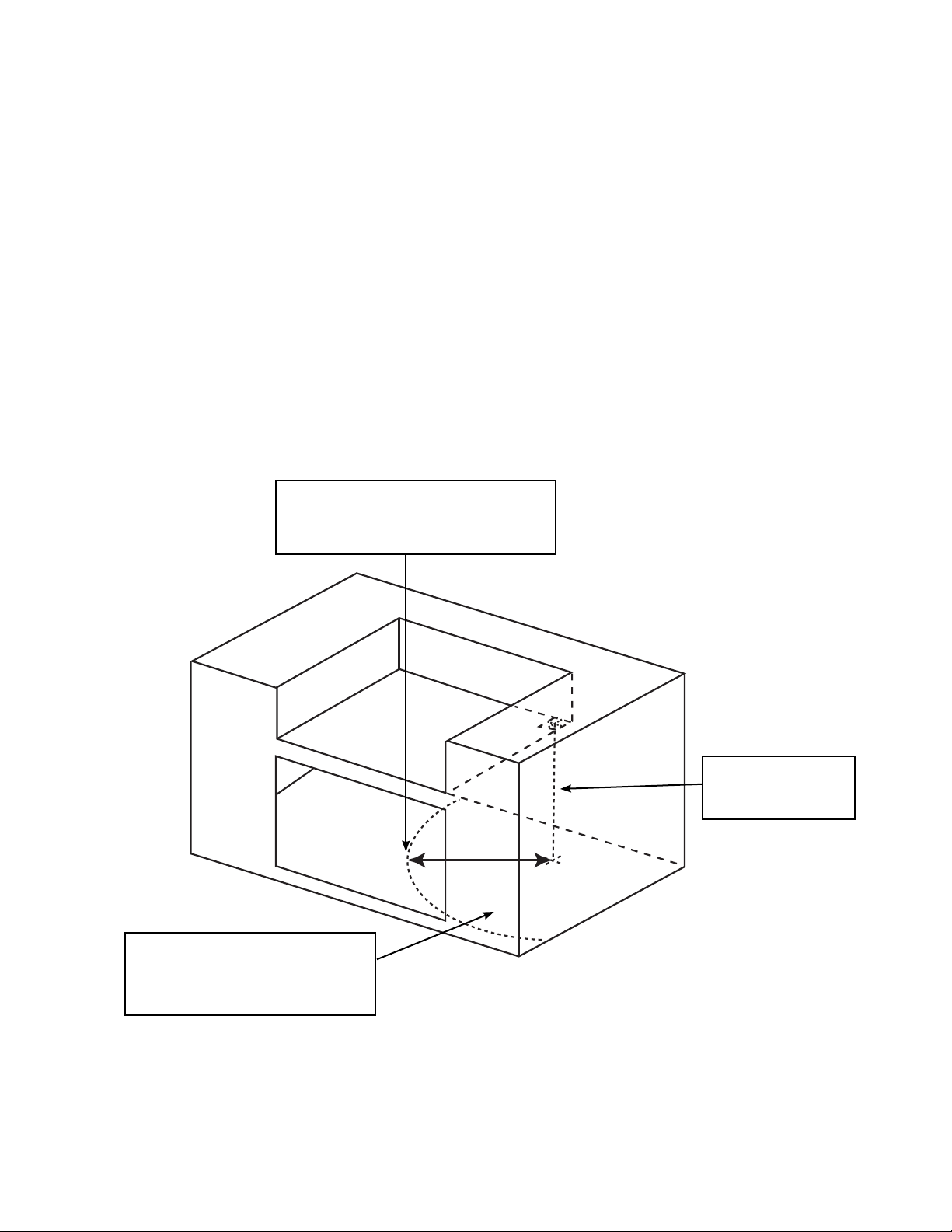
The maximum distance from the center
of the manifold cut out to the center of
the tank restraint is 18 inches.
Center of Tank Restraint must be
placed within this area to avoid
causing stress on the LP regulator
hose connection.
Center of manifold cut
out projected to floor
of the island.
18” max.
FIG. 10
14
Page 17
INSTALLATION
GAS HOOKUP
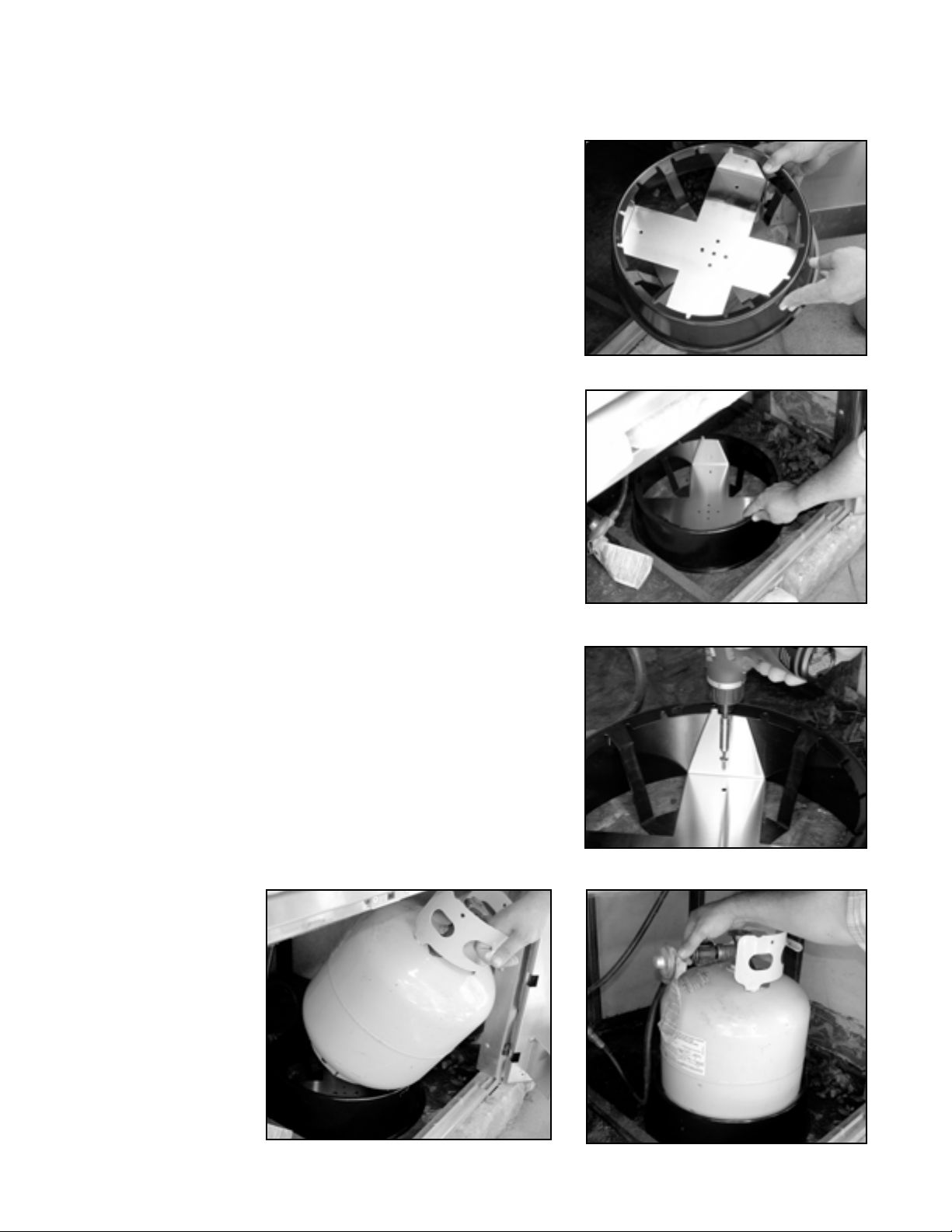
STEP 1
Place the tank restraint in the island (Fig. 11).
STEP 2
Locate the tank restraint in the island within the recommended area
(Fig. 10 and 12).
STEP 3
Once located, secure to the bottom of the island using all eight hole
locations provided on the restraint. Wood screws can be used for
wooden floors or 1/4 inch diameter anchor screws or bolts may be
used if the floor is concrete or masonry (Fig. 13).
STEP 4
When secure, place the LP cylinder into the tank restraint making
sure to seat the tank all the way down, securely affixing the tank in
the restraint (Fig. 14).
STEP 5
Attach the regulator hose assembly and operate the grill normally as
described in the Use and Care manual (Fig. 15).
FIG. 11
FIG. 12
FIG. 13
FIG. 14
FIG. 15
15
Page 18
INSTALLATION
LEAK TESTING
GENERAL:
Although all gas connections on the grill are leak tested at the factory prior to shipment, a complete gas tightness
check must be performed at the installation site due to possible mishandling in shipment, or excessive pressure
unknowingly being applied to the unit. Periodically check the whole system for leaks, or immediately check if the
smell of gas is detected.
Before Testing:
Do not smoke while leak testing. Extinguish all open flames. Never leak test with an open flame. Make a soap
solution of one part liquid detergent and one part water. You will need a spray bottle, brush, or rag to apply the
solution to the fittings. For LP units, check with a full cylinder. The valve panel must be removed to check the
valves and fittings. Remove the knobs and the safety valve knob, then remove the 2 screws which fasten the
valve panel to the unit (you will need a Philips screw driver for this). Pull the valve panel outward and unplug the
wires from the ignition module and the back of the ignition button. In the back of the unit remove the screws
which hold the service panel in place. Remove the service panel.
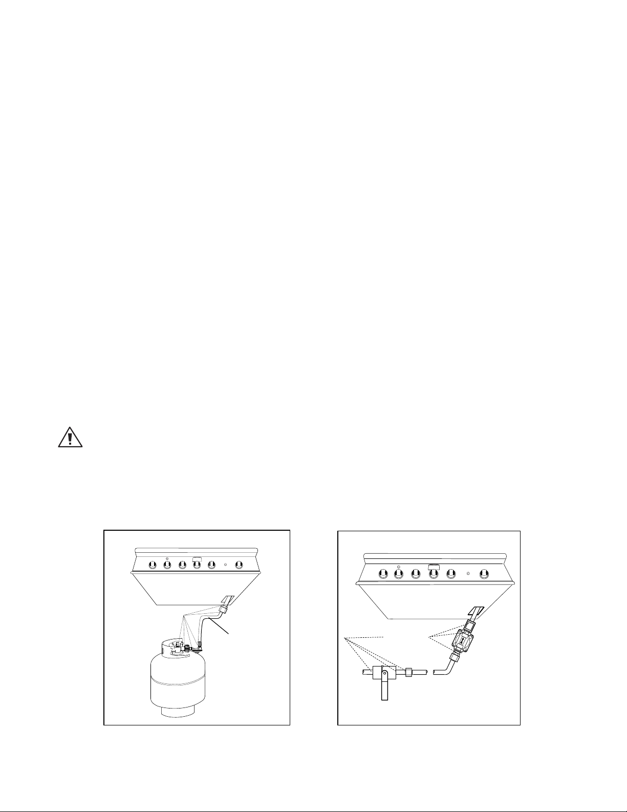
To Test:
Make sure all control valves are in the “OFF” position. Turn the gas supply “ON”. Check all connections from the
supply line, or LP cylinder up to and including the manifold pipe assembly. Apply the soap solution around the
connection, valve, tubing and end of the manifold. Soap bubbles will appear where a leak is present. If a leak is
present, immediately turn off gas supply, tighten any leaking connections, turn gas on, and recheck. Check all
the gas connections at the base of the control valves where they screw into the manifold pipe.
To check rotisserie burner and safety valve the burner must be lit, then leak test the connections located behind
the service panel. If you cannot stop a gas leak turn off the gas supply and call your local gas utility, or the dealer
you purchased the appliance from. Only those parts recommended by the manufacturer should be used on the
grill. Substitution can void the warranty.
WARNING!
Do not use the grill until all connections have been checked and do not leak.
Check all gas supply fittings for leaks before each use. Keep a spray bottle of soapy water near the gas supply
shut-off valve. Spray all the fittings. Bubbles indicate leaks (Fig. 16 & 17).
Bottom of unit
Bottom of unit
LEAK TEST POINTS
CHECK HOSE FOR
SIGNS OF ABRASIONS,
CRACKS, OR LEAKS
LEAK TEST POINTS
LP TANK
FIG. 16 LP Gas
FIG. 17 Nat. Gas
16
Page 19
"
INSTALLATION
BURNER ADJUSTMENT
GRILL BURNER AIR ADJUSTMENT:
Each grill burner is tested and adjusted at the factory prior to shipment; however, variations in the local gas
supply or a conversion from one gas to another may make it necessary to adjust the burners. The flames of the
burners (except the rotisserie burner) should be visually checked and compared to that of the drawing in Fig.18.
Flames should be blue and stable with no yellow tips (LP units may have some yellow tipping), excessive noise or
lifting. If any of these conditions exist, check if the air shutter or burner ports are blocked by dirt, debris, spider
webs, etc. Proceed with air shutter adjustment. The amount of air which enters a burner is governed by a metal
cup at the inlet of the burner called an air shutter. It is locked in place by a screw which must be loosened prior to
lighting the burner for adjustment.
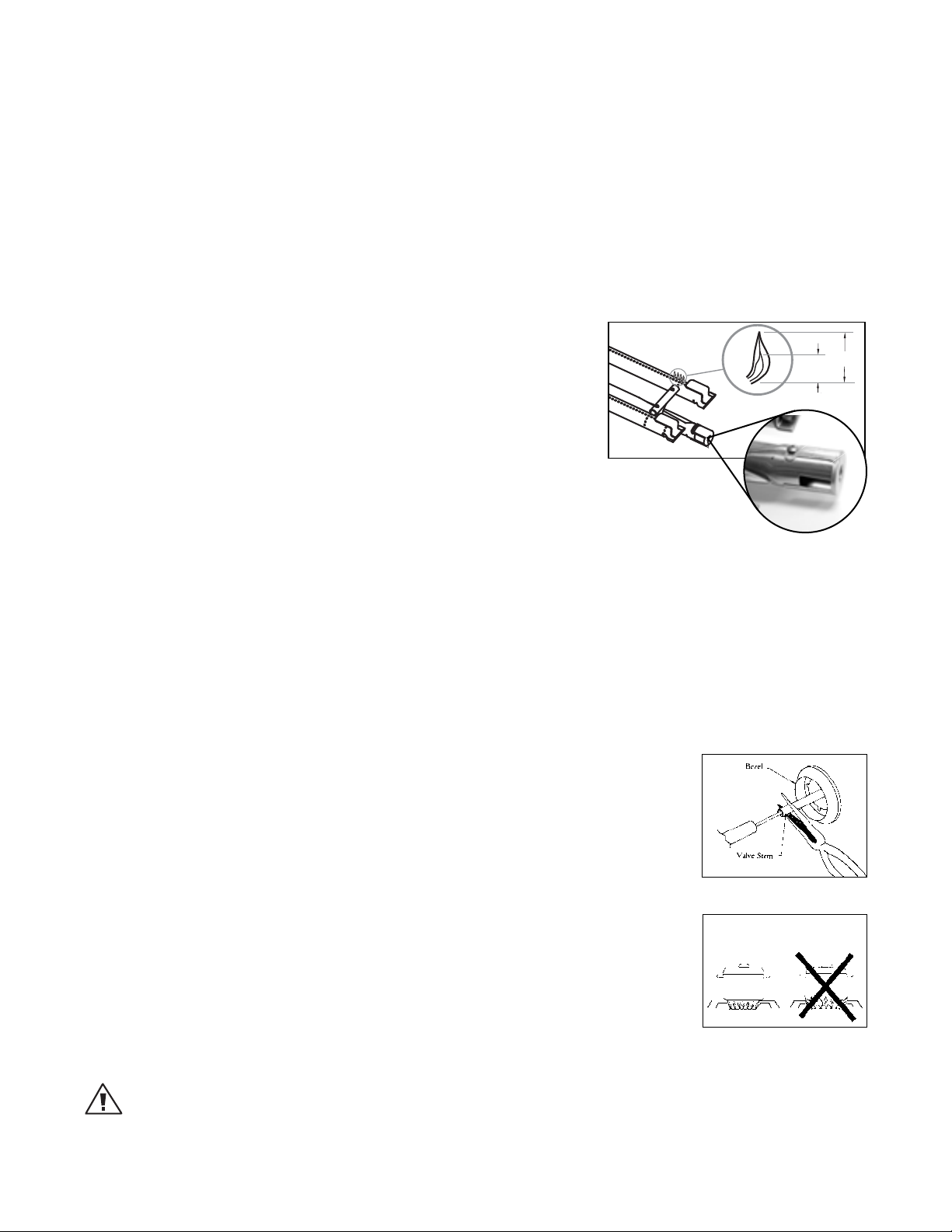
GRILL BURNER FLAME HEIGHT:
Before beginning, ensure the grill is OFF and cool. To access the grill
burner air shutters, first remove the grates and radiants from the firebox, then remove the grill burner using instructions shown on page 29,
Fig. 46. With a screw driver, loosen the lock screw on the face of the air
shutter slightly so that the air shutter can be adjusted.
To Adjust:
1. Be careful as the burner may be very hot.
2. If the flame is yellow, indicating insufficient air, turn the air shutter
counterclockwise to allow more air to the burner.
3. If the flame is noisy and tends to lift away from the burner, indicating too much air, turn the air shutter clockwise.
Reinstall the U-burner, ensuring the burner is level. Light the burner and check the flame. If all is okay, remove
the burner (CAUTION - burner may be hot, allow time to cool) and tighten the air shutter screw. If not repeat the
above procedure to readjust the air shutter.
FIG. 18 Burner Flame
Height
3/8"
CLOSE
1-1/2
OPEN
LOW FLAME SETTING ADJUSTMENT:
The valves on the grill feature an adjustable low setting. Due to fluctuations in gas pressure, heating value or gas
conversion, you may feel it necessary to increase or decrease gas flow in the low position. We do not recommend
adjusting the infrared rotisserie burner.
To Adjust:
1. Light the burner.
2. Turn the control knob to the lowest setting (all the way counter-clockwise).
3. Remove the knob.
4. While holding the valve shaft with pliers, insert a thin, flat tipped screwdriver into the
shaft and while viewing the burner adjust to a minimum stable flame (Fig. 19).
SIDE BURNER FLAME HEIGHT:
The correct height of the flame mainly depends on the size of the bottom of the cooking utensil, the material of the cooking utensil, the amount and type of food and the
amount of liquid in the utensil. Following are some basic rules for selecting flame
height.
■
For safety reasons the flame must never extend beyond the bottom of the cooking
utensil. Never allow flames to curl up the side of the pan (see Fig. 20).
■
Utensils which conduct heat slowly (such as glass-ceramic) should be used with me-
dium to low flames. If you are cooking with a large amount of liquid, a slightly larger flame can be used.
FIG. 19 Low Setting Adjustment
Proper Flame Height
Fig. 20
WARNING: IMPORTANT!
Before lighting, inspect the gas supply piping or hose prior to turning the gas “on”. If there is evidence of cuts, wear,
or abrasion, it must be replaced prior to use.
17
Page 20
INSTALLATION
RADIANT ASSEMBLY
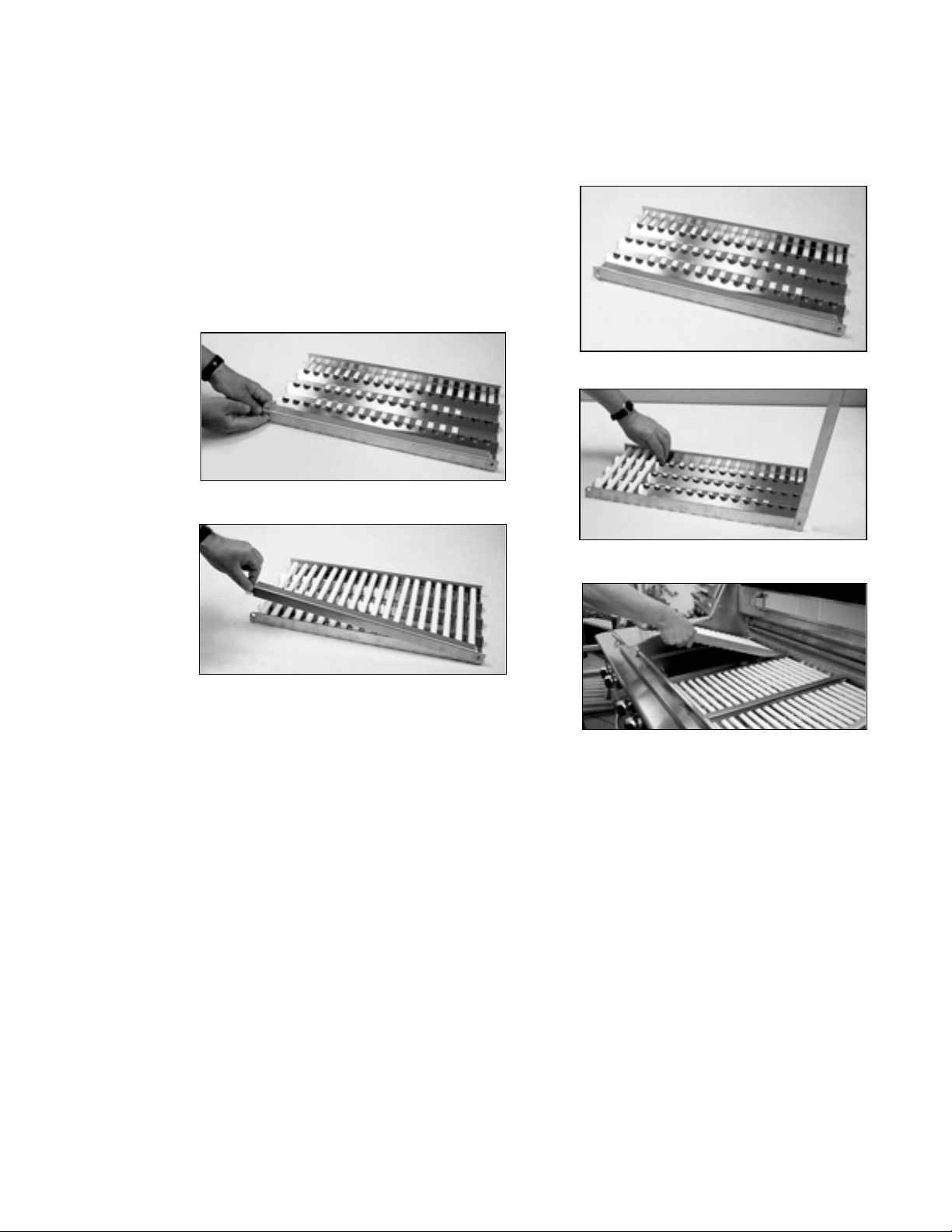
RADIANT ASSSEMBLY INSTALLATION:
1
. Unpack ceramic rods and remove radiant (Fig. 21) from the unit.
2
. Unlock radiant end cap by pushing it up with two fingers (Fig. 22).
3.
Place 18 ceramic rods on the radiant (Fig. 23).
4.
Lock radiant end cap (Fig. 24).
5.
Place the assembled radiant in the unit (Fig. 25).
FIG. 22
FIG. 21
FIG. 24
Note:
In case a ceramic rod breaks:
a) Unlock radiant end cap by pushing it up with two fingers (Fig. 16) or pliers may be used.
b) Replace broken ceramic rod.
c) Lock radiant end cap.
FIG. 23
FIG. 25
18
Page 21
INSTALLATION
INSTALLER CHECKLIST
❏ Specified clearances main-
tained to combustibles.
❏ Verified proper enclosure
ventilation.
❏ All internal packaging
removed.
❏ Removed shipping brack-
ets
❏ Knobs turn freely, bezels
centered.
❏ Each burner lights satis-
factorily, individually or
with adjacent burner lit.
❏ Air shutters adjusted.
❏ Low flame setting satis-
factory.
❏ Drip pan in place properly
and sliding freely.
❏ Pressure regulator con-
nected and set for 4.0”
W.C. Natural, 11.0” W.C. LP
gas.
❏ Manual shut-off valve
installed and accessible.
❏ Unit tested and free of
leaks.
❏ User informed of gas
supply shut-off valve
location.
❏ All radiants are assembled
and put in place.
❏ Check match lighting.
■
PLEASE LEAVE THESE
INSTRUCTIONS WITH THE
USER.
■
USER, PLEASE RETAIN
THESE INSTRUCTIONS
FOR FUTURE REFERENCE.
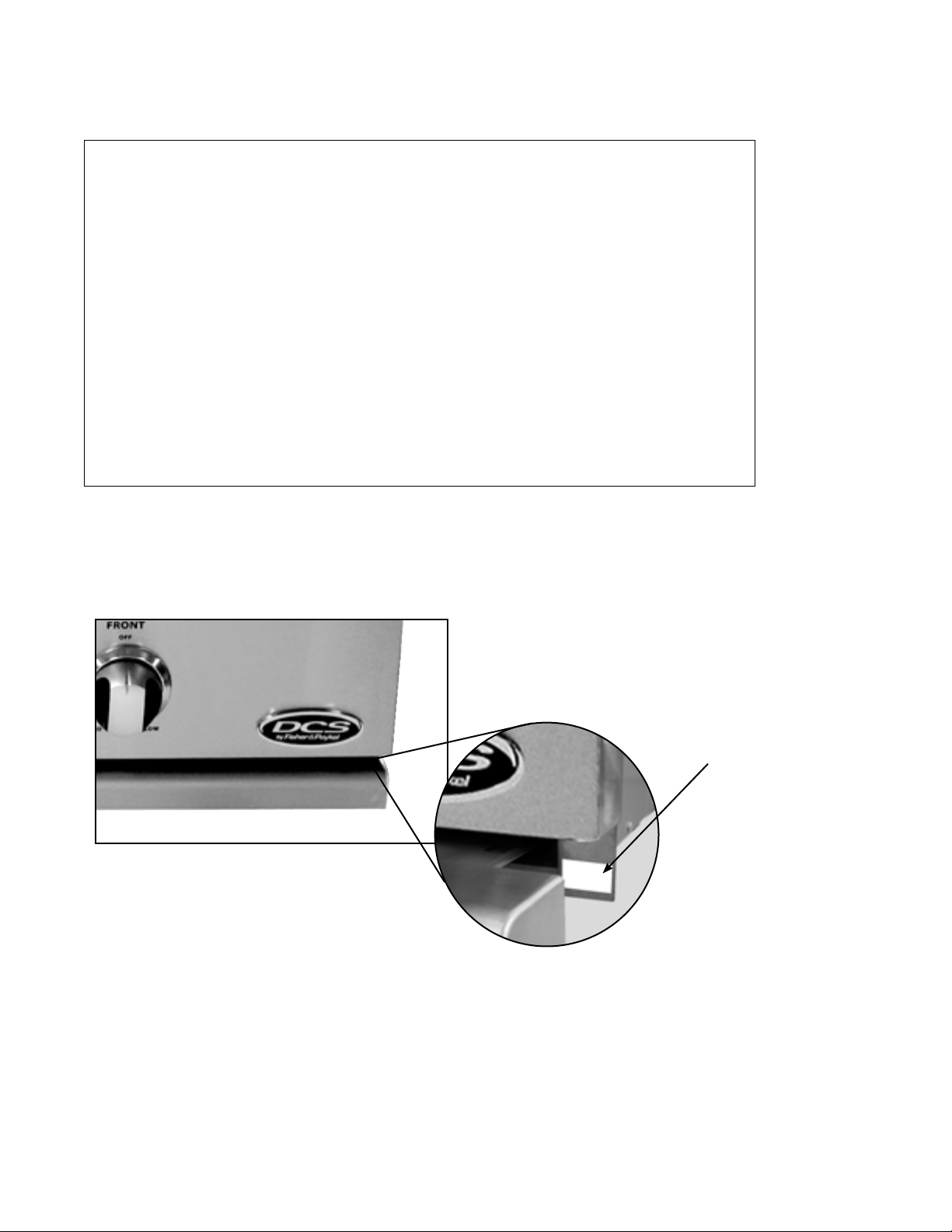
NOTE:
If any of the listed items are missing, contact DCS at (888) 936-7872. Please be prepared with your
Model #, Serial # and description of item(s) that are missing.
Tag location of
Model # and Serial #
Read all installation instructions in this manual to see if the unit has been properly installed. If not done or
done correctly, correct before using the unit.
19
Page 22
USING THE GRILL
LIGHTING INSTRUCTIONS
TO LIGHT THE GRILL BURNER:
Open the grill lid and/or remove the top grate cover from side burner (for 48BQR) before lighting. Turn all knobs
to “OFF”. Turn the main gas supply on slowly. If you smell gas, shut off gas supply and call for service.
Push and hold the ignition button, turn the selected burner knob to “SEAR”. If burner does not light in 4 to 5 seconds, turn knob “OFF” and wait 5 minutes before trying again for any accumulated gas to dissipate.
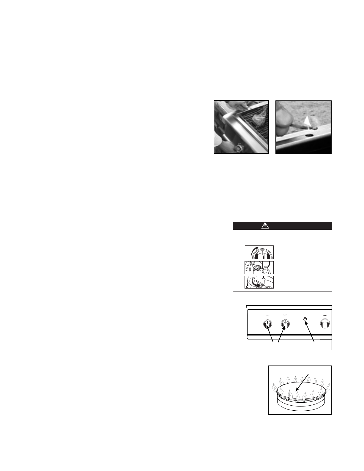
Grill Match Lighting:
If the burner will not light after several attempts then the burner
can be match lit. If you’ve just attempted to light the burner with
the ignition, allow 5 minutes for any accumulated gas to dissipate.
Keep your face as far away from the grill as possible and hold and
pass a lit, paper book match over the hole located on the top left
for burner on the left, or the right hole for the right burner (Fig. 26
& Fig. 27). Push and turn the control knob which is centered on the
burner where the lit match is located, to “SEAR/HI”. If the burner
does not light in 4 seconds, turn the knob off, wait 5 minutes and try again.
Once the left or right burner is lit, the adjacent burner can be lit by the cross-lighting method. For center
burners to cross light, light the adjacent far left or right burner using the standard or match light procedure.
Push and turn the control knob for the desired center burner to “HI”. The gas will be ignited by the adjacent burners flame. If the burner does not light in 4 seconds, turn knob off, wait 5 minutes and try again.
FIG. 26
FIG. 27
NOTE:
Improper lighting procedures can cause the LP tank flow control to activate,
resulting in reduced heat output. If this is suspected, to reset flow control,
shut off all burner controls and LP cylinder valve, wait 30 seconds, then turn
LP cylinder valve on extremely slowly, wait five (5) seconds and push and
hold the ignition button and turn burner valve on to “SEAR”.
TO LIGHT DUAL SIDE BURNERS 48BQR MODELS ONLY:
CAUTION!
The side burner cover may be hot if the grill burners are in operation.
Side Burners Lighting Instructions:
First remove the burner cover and any cooking utensils from the burner grate.
Push and hold the ignition button, turn the control knob to the “HI” position
until the burner is lit or 4 seconds pass. If the burner doesn’t ignite, wait 5
minutes for any accumulated gas to dissipate then try again. If the burner
will not light after several attempts, check the trouble shooting instructions
on page 31.
Side Burners Match Lighting:
Hold a lit paper book match near the burner ports, turn the control knob
counterclockwise to “HI”. Move your hand immediately once the burner is
lit. Rotate the control knob to the desired setting.
WARNING
Failure to follow the steps in the order shown may cause the Flow
Limiting Device to activate resulting in extremely low gas ow and
improper operation.
OFF
1
SEAR
2
3
All knobs must be in the OFF position before
opening LP tank valve.
Attach regulator hose assembly to tank.
Now open the LP tank valve two (2) full
turns min.
Control Knobs
FIG. 28
IGNITION
Ignition
Cap
Note:
If you are using propane gas, a slight pop or flash may occur at the burner ports a few
seconds after the burner has been turned “off”. This “extinction pop” is normal for
propane gas.
FIG. 29
Side burners:
Your side burner is equipped with burners typical of those used in restaurants. These burners are designed for
maximum cleanability and controlability. The burner should never be operated if the cap is not in place (Fig. 29).
20
Page 23
USING THE GRILL
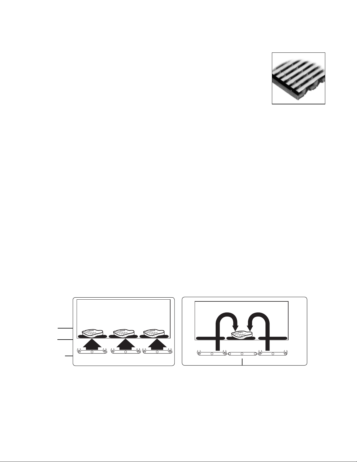
HEAT HEAT
HEAT HEAT HEAT
GRILLING
GRILL:
Each grill section consists of a large stainless steel burner, stainless steel heat baffles,
a series of ceramic rods encased in a stainless steel radiant, and a stainless steel heat
retaining grate. Each burner is rated at 25,000 Btu/hr. Below the burners there is a stainless steel heat baffle which reflects usable heat upward into the cooking area and reduces
temperatures of the drip pan below. Above the burners are stainless steel radiants which
encase the ceramic rods and protect the grill burner ports from blockage (Fig. 30).
The grill is supplied with radiant ceramic rods. Because of the porosity of ceramic rods,
performance is superior in the rods’ ability to capture heat as it rises from the grill burners. They also possess the thermal mass needed for even cooking performance. Flare ups are controlled because
the radiant ceramic rods keeps grease from getting to the flames and igniting. The intense heat produced by
this system produces true grilled flavor as fats and juices are brought to the surface of the food and caramelized.
Discoloration of the grates are normal after use.
FIG. 30
DIRECT/INDIRECT COOKING NOTES:
Direct cooking involves placing food on grates over lighted burners. Use this method for foods that take less than
20 minutes to cook or to sear larger items at the start of the cooking process that will then be indirectly cooked to
finish. Place items on the preheated surface and leave until they no longer stick. Turning too soon and too often
is one of the most common grilling mistakes. Never spray water on the grill or into grease. The patented Grease
Management System™ reduces flare-ups by channeling grease away from the flame. Use a meat thermometer to
achieve desired doneness and remove items one degree below how you would like to enjoy them, as the resting
period before carving or consuming will raise the temperature.
Indirect cooking method is a popular alternative to direct heat grilling. Indirect cooking uses heat from adjacent
burners to cook food and, in many cases, reduces the possibility of overcooked or overly browned food. Foods
most appropriate for indirect grilling included breads, thicker pieces of chicken or steaks. Indirect cooking involves placing the food on grates where the burners below are not lit and then closing the grill top to create an
oven effect. All the items you usually oven-roast can be grilled to perfection using indirect heating. Preheat the
burners surrounding the food to be cooked. Use you grill to hold food and add water or chicken broth to the pan
to prevent the natural juices from burning or evaporating.
Direct Heat Grilling
(Hot Dogs, Hamburgers, Typical
Thickness Steaks/Chicken)
Indirect Heat Grilling
Food
Grill
Rack
Burner
IMPORTANT
To season the grates, pour a tablespoon of vegetable oil on a soft cloth and rub on both sides of the grates.
Only a light coating is needed and some smoke may be visible during the preheating. Grilling requires high
heat for searing and proper browning. Most foods are cooked at the “MEDIUM” to “LOW” heat setting for the
entire cooking time. However, when grilling large pieces of meat or poultry, it may be necessary to turn the
heat to a lower setting after the initial browning. This cooks the food through without burning the outside.
Foods cooked for a long time or basted with a sugary marinade may need a lower heat setting near the end of
Using the Grill:
Burner Off
21
Page 24

USING THE GRILL
GRILLING Continued
the cooking time.
1. Check to be certain the drip pan and grease tray are in place.
2. Light the grill burners using the instructions on page 20.
3. Preheat the grill for 5 to 10 minutes. Once you have verified the burners are lit, put the lid down to preheat.
4. Place the food on the grill and cook to the desired doneness. Adjust heat setting, if necessary. The control
knob may be set to any position between “SEAR” and “LO” - most grilling done is between “MED” and “LO”
settings.
5. Allow grill to cool and clean the grates, drip pan and grease tray after each use.
Note:
If using LP gas, your preheat time may be shorter than recommended. To prevent overcooking or burning, you may
want to lower heat settings.
GRILLING HINTS:
The doneness of meat, whether rare, medium, or well done, is affected to a large degree by the thickness of the
cut. Expert chefs say it is impossible to have a rare doneness with a thin cut of meat. The cooking time is affected
by the kind of meat, the size and shape of the cut, the temperature of the meat when cooking begins, and the
degree of doneness desired. When defrosting meats it is recommended that it be done overnight in the refrigerator as opposed to a microwave. This in general yields a juicier cut of meat. Use a spatula instead of tongs or a
fork to turn the meat, as a spatula will not puncture the meat and let the juices run out. To get the juiciest meats,
add seasoning or salt after the cooking is finished and turn the meat only once (juices are lost when the meat is
turned several times). Turn the meat just after the juices begin to bubble to the surface. Trim any excess fat from
the meat before cooking. To prevent steaks or chops from curling during cooking, slit the fat around the edges at
2-inch intervals.
DUALSIDED GRATES:
Whether you or your guests crave seafood, steak or veggies, the double-sided grates provide varying surfaces
for varying textures. The “W”-shaped side creates nice sear lines for steaks, chicken and chops and routes oil and
grease away from the food. The opposite “radius” side offers more surface area for support and handling of delicate items like scallops. (See below for a sample list of which foods to cook on which side of the grate.) Keep the
grates mixed–half on one side and half on the other or a percentage that best represents what you are cooking.
“W”-SHAPED GRATE RADIUS GRATE
• chicken (bone-in and boneless cuts)
• steaks
• chops
• burgers
• ribs
• kabobs
• steak cuts of fish like tuna and swordfish
• whole fish
• game
• oysters
• large slices of whole vegetables and mushrooms
• fruit
• bread
• sausages
• hot dogs
• delicate fish fillets
• lobster meat
• shrimp
• scallops
• clams
• mussels
• suckling pig
• turkey legs
• indirect cooking and smoking
• potatoes
• smaller vegetables or slices
• roasted peppers
• roasted whole garlic
• pizza dough and flat breads
• crab cakes
22
Page 25

USING THE SMOKER SYSTEM
The smoker system on each grill consists of a stainless steel slide out tray
which is positioned above a 3,500 Btu/hr burner. The burner is controlled
by a precision brass valve which is capable of being turned down to very low
heat levels. The system may be used alone for low temperature roasting and
smoking or in conjunction with any combination of other burners. When
using the smoker system in conjunction with the optional infrared rotisserie
burner, you’ll find it helpful to use the low setting of the smoker burner to
minimize the heat rising up to the rotisserie basting pan. Staggering the
meat away from the smoker burner also helps.
To minimize burn potential do not completely remove the smoker tray when
hot.
FIG. 31 36 / 48 Grill Smoker System
TO LIGHT THE SMOKER BURNER:
Open the lid and remove the smoker tray. Locate the burner visually by
looking through the cut-out in the valve panel. Push and hold the ignition
button, turn the control knob to the “HI” position until the burner is lit or 4
seconds pass. If the burner doesn’t ignite, wait 5 minutes for any accumulated gas to dissipate, then try again. If the burner will not light after several attempts, wait 5 minutes, then match light using a paper book match through
the cut-out in the valve panel. Once lit, fill the smoker tray and replace.
WOOD CHIPS:
There are many wood chips available for purchase and selection is based
on personal taste. The most common wood chips used are mesquite or
hickory. Mesquite has a sweeter taste and is commonly used with poultry
and seafood. Hickory is best suited for red meats. Use of oak, cherry, maple, aspen or apple is also common while
aromatic herbs like sage, bay leaves, thyme or basil may also be used. Soaking the chips in water before using
them will help ensure the wood chips smoke and do not flame up. To start, you may want to use the “HI” position
to start the chips smoking, then reduce the heat to a lower level to prevent them from drying out and flaming. If
the wood chips do flame up, add a small amount of water to extinguish the flame. This should be done carefully
through the top in the grill area, or by pulling the tray out slightly. Use caution when adding water to a hot tray
to avoid steam burns, and never completely remove a hot tray. When smoking, the lid should remain closed as
much as possible to maximize the effect. During extended roasting periods it is normal to add fresh wood chips
to the tray several times.
FIG. 32
23
Page 26

USING THE ROTISSERIE
The grill rotisserie system is designed to cook items from the
back using infrared heat. The location of the burner allows the
placement of the rotisserie basting pan (included) beneath the
food to collect juices and drippings for basting and gravy. To
flavor the contents of the basting pan, you can add herbs, onion,
garlic, or spices. Hams are especially good with the addition of
pineapple slices and brown sugar to the basting pan. The rotisserie burner is an infrared type which provides intense searing
radiant heat. Preferred by chefs over other methods, this intense
heat is magnificent for searing in the natural juices and nutrients
found in quality cuts of meat.
Once lit, the rotisserie burner will reach cooking temperatures in
about 1 minute. The orange/red glow will even out in about 5
minutes. The rotisserie motor is equipped with metal gears and is capable of turning up to a 25 lb. cut of meat or
poultry. The rotisserie motor on the grills is secured down to a cast rotisserie block with two black screw- down
knobs. The rotisserie block is in turn bolted to the right side panel. The rod for the rotisserie is assembled into
the motor assembly by placing the pointed end into the motor, and resting the handle end on the support at the
left side of the grill. With the rod pushed as far as possible into the motor, the grooved rod should rest on the
rollers.
FIG. 33
To load the rod begin with the handle in place, and slide one of the meat holders (prongs facing away from the
handle) onto the rod. Push the rod through the center of the food, then slide the second meat holder (prongs
toward the food) onto the rod. Center the product to be cooked on the rod then push the meat holders firmly together. Tighten the ‘L’- shape screw with pliers. It may also be necessary to wrap the food with butchers string or
dental floss (never use nylon or plastic string) to secure any loose portions.
Once the food is secure, insert the rod into the motor. If needed, remove
the grill grates. Place the basting pan beneath the food. It is normal for
the rod to flex when larger cuts of meat are being cooked.
Also, the motor is equipped with a halogen bulb to provide light when
other sources of light are not sufficient. Use only a 50W Max. Halogen Narrow Flood replacement bulb.
ROD
LIGHT
WARNING!
Halogen lamps are constructed of a glass bulb with a pressurized internal
filament tube that operates at high temperatures and could unexpectedly
shatter. Should the outer bulb break, particles of extremely hot glass could
be discharged into the fixture enclosure and/or surrounding environment,
thereby creating a risk of personal injury or fire. When replacing the bulb, let
the bulb cool, and assure that power to the light has been turned off. Never
allow the hot bulb to come into contact with water. DO NOT TOUCH the
light bulb when in use. It may be hot enough to cause injury.
MOTOR
FIG. 34
24
Page 27

USING THE ROTISSERIE
WARNING!
Never have the grill burners (bottom burners) on during Rotisserie cooking. It will burn your meat and make it very
dry. Use only one section at a time, grill or rotisserie.
PREPARATION
Recommended:
Dental floss or butcher string, scissors, broiler pan (bottom only), pliers, instant read thermometer, foil, and hot
pads.
Working Area:
Allow enough space to accommodate food and rotisserie rod
assembly in a clean environment.
Meat Preparation:
Tie meat with butcher string or Dental floss in three areas. Buy
a roast that is equally balanced from top to bottom in size.
The meat will cook more evenly while on the Rotisserie. For
Poultry, tie wings and legs to the body using Dental floss or
butcher string to prevent flopping around while turning.
(Fig. 35)
1. Determine the center placement for the food, put first prong
on the rod, turn ‘L’- shaped screw to tighten.
2. Center tied meat/poultry on the rod, place second prong, turn ‘L’- shape screw to tighten. (Fig. 36)
3. Pick up the rod, rotate it to check for balance. If not, adjust prongs and food to balance. Take pliers and tighten
the ‘L’- shape screws on both sides of the prong.
4. Remove grates and top rack on the grill. Place bottom portion of broiler pan on ceramic rods, so meat drippings
can be caught in pan. (Fig. 37).
FIG. 36
FIG. 37
FIG. 35
25
Page 28

USING THE ROTISSERIE
TO LIGHT THE ROTISSERIE BURNER BEFORE COOKING:
The location of the rotisserie burner makes it more susceptible to strong wind conditions, more so than the
protected grill burners. For this reason you should avoid operating the rotisserie during windy conditions. As an
added safety feature we’ve equipped the burner with an automatic safety valve which will not allow gas to flow
to the rotisserie burner unless the following conditions are present with the knob on:
1. The safety valve button is pressed, and held down.
2. The safety valve thermocouple has been sufficientlyheated to keep safety valve open.
Open the lid. Push and hold the ignition button. You’ll hear a snapping sound. Turn the control knob to “HI”.
Engage the safety valve button and continue to hold until the burner is lit. Once lit, turn control knob to desired
setting. If the burner does not light within 4 to 5 seconds, release the safety valve button and turn the control
knob to “OFF” and wait 5 minutes before trying again.
■
If relighting a hot burner, wait 5 minutes.
■
Never leave the control knob on if rotisserie is not in use.
■
Never light a grill burner under the rotisserie while rotisserie burner is lit.
MANUAL LIGHTING:
To manually light the rotisserie, place a butane lighter near
the tip of the thermocouple as shown in Fig. 38. Turn the
control knob to “HI”. Hold the safety valve button in for
about 4 to 5 seconds or until the burner remains lit. Once
lit, turn control knob to desired setting. If the burner does
not light within 4 or 5 seconds, release the safety valve
button and turn the control knob to “OFF” and wait 5 minutes before trying again.
Thermocouple
WARNING!
Keep hands and face away from front of burner! STAND TO
THE SIDE WHEN LIGHTING. ONCE LIT MOVE HAND AWAY
QUICKLY.
FIG. 38
WARNING!
Electrical Grounding Instructions: This appliance (rotisserie motor) is equipped with a three-prong (grounding) plug
for your protection against shock hazard and should be plugged directly into a properly grounded three-prong
receptacle or a three-prong grounded extension cord rated for outdoor use. Do not cut or remove the grounding
prong from this plug. Use only a ground fault interrupter (GFI) protected circuit.
The rotisserie motor must be electrically grounded in accordance with local codes or, in the absence of local
codes, with the National Electrical Code, ANSI/NFPA 70-1990. Keep the rotisserie motor electric cord away from
the heated surfaces of the grill. When not in use, remove and store the motor in a dry location. To protect against
electric shock, do not immerse the cord or plug in water or other liquid. Unplug rotisserie unit from the outlet
when not in use and before cleaning. Allow the rotisserie to cool before putting on or taking off parts.
26
Page 29

USING THE ROTISSERIE
COOKING ON ROTISSERIE
1. Place prepared rod into motor, lay across to other side in groove (Fig.39).
2. Verify placement as shown in Fig. 40.
3. Ignite burner, start rotisserie motor, and keep on rotisserie valve on “high” for cooking all meats on the rotisserie.
4. To check temperature of the meat, turn off motor, turn temperature to low while using your instant-read thermometer. For poultry it should read 170º in the breast. Thermometer should touch the breastbone, then lift up
3/4 inch from the bone to get a more accurate temperature reading. Remove thermometer and turn on motor,
return heat to high if more cooking is needed. Repeat above instructions (Fig. 41).
5. Remove the rod, using hot pads, place meat or poultry on broiler pan, then remove prongs (Fig. 42).
WARNING!
The fork rods are very sharp. Keep hands away from tips when removing the food.
6. Cover with foil for a 15 to 20 minute waiting time. Meat will carve better and juices will go back into the meat.
FIG. 39
FIG. 41
FIG. 40
FIG. 42
27
Page 30

CARE AND MAINTENANCE
BATTERY REPLACEMENT:
1. Remove drip pan.
2. Open cart door (on cart model only).
3. Pull battery downwards (This may require use of pliers).
4. Re-install upward and push to snap - Fig. 43. (Polarity is
shown in Fig. 44).
Note:
Battery condition should be checked at least once a year.
FIG. 43
REGULATOR AND HOSE REPLACEMENT
The pressure regulator and hose assembly supplied with the unit must be used. If replacements are needed, contact Customer Care (888) 936-7872. Do not use the grill if the odor of gas is present. If the unit is LP, screw the
regulator into the tank and leak check the hose and regulator connections with a soap and water solution before
operating the grill. Turn all knobs to “OFF” then turn on the gas supply. If LP, is there gas in the tank?
■
Always keep your face and body as far away from the grill as possible when lighting.
■
DO NOT leave the grill unattended while cooking.
■
Keep a spray bottle of soapy water near the gas supply valve and check the connections before each use.
■
Do not attempt to “LITE” the grill if the odor of gas is present.
■
Wait 5 minutes before relighting a hot grill.
GRILL GRATES:
Method 1: Turn on “HI” for 15-20 minutes to burn any remaining food particles. After turning the grill “OFF”, use a
bristle barbeque brush to remove any remainin food particles or ash.
FIG. 44
Method 2: The easiest way to clean the grill is immediately after cooking is completed and after turning off the
flame. Wear a barbeque mitt to protect your hand from the heat and steam. Dip a soft brass bristle barbeque
brush in a mixture of 2 cups of tap water and 1/2 cup of vinegar and scrub the hot grill. Dip the brush frequently
in the bowl of water and vinegar. Steam, created as water contacts the hot grill, assists the cleaning process by
softening any food particles. The food particles will fall onto the ceramic rods and burn or fall into the drip pan.
If the grill is allowed to cool before cleaning, cleaning will be more difficult.
Method 3: Take about 1 foot of aluminum foil, crumbled up in a ball and rubbing it over cooled grates to release
food particles.
Note:
Grill grates must be re-seasoned after cleaning to prevent rust stains.
DRIP PAN AND GREASE TRAY:
The full width drip pan with grease tray will collect grease from the grill section and boil overs and spills from the
side burners. Allow the pan and its contents to cool before attempting to clean. Clean grease from the pan often
to avoid the possibility of a grease fire.
CERAMIC RODS:
It is not necessary to remove the ceramic rods for cleaning. They burn themselves clean during the next cooking
operation. Periodically the trays holding the ceramic rods need to be turned over, and shaken free of debris for a
thorough cleaning. How often you use the grill and the amount and type of food cooked will determine when it
is necessary to clean the trays. If grease can be seen on the top of the tubes or if you get a lot of flare-up during
cooking, the tubes need to be turned over and heated on “HI” for 30 minutes; longer for heavy soil.
28
Page 31

CARE AND MAINTENANCE
STAINLESS STEEL:
The grill is made from non-rusting and non-magnetic stainless steel. After initial usage, areas of the grill may discolor from the intense heat given off by the burners, this is normal. There are many different stainless steel cleaners available. Always use the mildest cleaning procedure first, scrubbing in the direction of the grain. To touch up noticeable scratches in
the stainless steel, sand very lightly with wet 100 grit emery paper in
the direction of the grain. Specks of grease can gather on the surfaces
of the stainless steel and bake on to the surface and give the appearance of rust. For removal use an abrasive pad (Scotch Brite is good) in
conjunction with a stainless steel cleaner. Always rub in the direction of
the grain.
Note:
Stainless steel tends to corrode in presence of chlorides and sulfides especially in coastal areas. To ensure corrosion prevention, wash all stainless
steel surfaces every 3-4 weeks with fresh water and stainless cleaner. Keep
grill covered when not in use.
ELECTRODES:
Wipe with a water dampened cotton swab. Be careful not to damage
the electrode (see Fig. 45).
ELECTRODE (KEEP CLEAN)
FIG. 45
GRILL BURNER:
Ensure gas supply has been turned off. Remove the grill grates, then
lift out the grill radiant tray. Grasp the burner, pull it up and slightly to
the rear of the unit so the burner head comes off the brass orifice at the
front, angle the burner sideways, and remove.
TO REMOVE THE UBURNERS FOR CLEANING
Grip the U-burner as shown in the photo (Fig. 46) and press downwards
with your thumbs on the bracket in the back while lifting up on the UBurner. In some cases it may be necessary to use a screw driver to pry
open the slot to release the U-burner. After cleaning, when re-installing
the U-Burner ensure the U-Burner is completely level and locked in
place. This is needed to ensure your grill provide even cooking performance.
FIG. 46
GRILL BURNER CLEANING:
Clean the exterior of the burner with a stainless steel wire brush. Clear
stubborn scale with a metal scraper. Clear any clogged ports with a
straightened paper clip. Never use a wooden toothpick as it may break
off and clog the port. Shake out any debris through the air shutter. Use
a flashlight to inspect the burner inlet to ensure it is not blocked. If
obstructions can be seen, use a metal wire coat hanger that has been
straightened (See Fig. 47).
FIG. 47
ORIFICE CLEANING:
With the burner removed, remove the orifice and shine a flashlight through the opening to ensure there is no
blockage. Use a needle to clear any debris. Be extremely careful not to enlarge the hole or break off the needle
(Fig. 47).
29
Page 32

CARE AND MAINTENANCE
Note:
Fig. 48
When replacing grill and/or smoker burners, or orifices following cleaning, confirm orifice penetration into burner as
shown in Fig. 48
Be careful not to upset the air shutters’ original position (unless readjusting). Lower the rear of the burner
into the cutouts on the support channel at the rear of
the burner box. Make sure it is level and does not rock.
Light all of the burners and check for proper flame
characteristics. If adjustments are necessary, refer to
page 17. Do this prior to cooking on the grill.
SIDE BURNERS BGB48 BQR MODEL:
For proper lighting and performance keep the burners clean. It is necessary to clean the burners if they
do not light even though the electrode clicks, if there
has been a severe boil over, or when the flame does
not burn blue. Be certain all burner knobs are in the
off position before attempting to clean the burners.
The burners have been designed for ease in cleaning. When the grates and burners are cool, remove
the grate. The burner cap and the brass port ring can
easily be lifted off. Wash these parts in hot soapy
water, rinse and dry thoroughly. The burner caps are
porcelain enamel. Follow the directions on the previous page for cleaning that were given for the burner
grates. A bristle brush can be used to clean out the
toothed burner ports, if necessary. After cleaning, it is
important to make sure the location pins on the bottom side of the port ring are properly aligned with the
corresponding holes in the base. Incorrect alignment
will produce a potentially dangerous flame and poor
burner performance (see Fig. 49).
Brass Ring
Locating Pins
Locating Notch
Electrode
Locating Holes
FIG. 49
Cap
Main
Burner
Port Ring
Burner
Base
Venturi
SMOKER BURNER:
The smoker burner can be removed and cleaned by unplugging the electrode wire and lifting out the burner.
Cleaning is similar to the grill burner. Replace the burner by sliding the air shutter over the brass orifice, centering it in the hole.
30
Page 33

TROUBLESHOOTING
BEFORE CALLING FOR SERVICE:
If the grill does not function properly, use the following checklist before contacting your dealer for service. You
may save the cost of a service call. Troubleshooting is for general purposes only. If the problem persists and you
feel you require service, contact your dealer or the nearest authorized agency to perform service. Only authorized agencies can perform warranty service. Call DCS Customer Care at (888) 936-7872.
GRILL WON’T LIGHT WHEN THE IGNITION BUTTON IS PUSHED:
1. Is the gas supply turned on?
2. Ensure the grill is cool. Remove the grill top grates and the ceramic radiant trays, watch the electrode tip. You
should see a spark jump from the tip of the ignition when the ignition button is pushed.
3. If there is no spark when ignition button is pushed, check the battery condition. Battery condition should be
checked at least once a year.
4. Attempt to match light the burner (see page 20 & 26). Check to see that other burners on the unit operate. Clean
electrode tip of any debris.
BURNER FLAME IS YELLOW OR ORANGE, IN CONJUNCTION WITH THE ODOR OF GAS:
1. Check the burner inlet for obstructions such as spider webs. Check the air shutter for proper adjustment.
2. Grill may be in a dusty area. Move to less dusty area if possible.
LOW HEAT WITH KNOB IN “HI/SEAR” POSITION:
1. If only one of the burners appears low, clean the orifice and burner, clearing ports of any obstruction
(see page 29).
2. Grill may be in a dusty area. Move to less dusty area if possible.
3. Check for proper gas supply and pressure.
4. Pre-heat grill for a full 15 minutes.
5. If using LP gas, check for empty tank.
ROTISSERIE WON’T LIGHT:
1. Is the gas supply turned on?
2. Is there is a spark at the electrode?
3. Does the rotisserie burner light when attempting to light with butane lighter?
ROTISSERIE LIGHTS, BUT WILL NOT HOLD FLAME ONCE BUTTON IS RELEASED:
1. Continue holding safety valve button in depressed position until burner remains lit when released.
31
Page 34

SERVICE
HOW TO OBTAIN SERVICE:
For warranty service, please contact your local service provider or DCS Customer Care at (888) 936-7872. Before
you call, please have the following information ready:
■
Model Number (can be found on the inside, right side panel behind the drip pan handle. See page 19.)
■
Serial Number (can be found on the inside, right side panel behind the drip pan handle. See page 19.)
■
Code (can be found on the inside, right side panel behind the drip pan handle. See page 19.)
■
Date of installation
■
A brief description of the problem
Your satisfaction is of the utmost importance to us. If a problem cannot be resolved to your satisfaction, please
write.
Fisher & Paykel Appliances, Inc.
Attention: DCS Customer Care
5900 Skylab Road
Huntington Beach, CA 92647
www.dcsappliances.com
32
Page 35

WARRANTY
LIMITED WARRANTY
When you purchase a new DCS Grill by Fisher & Paykel, you automatically receive a One Year Limited Warranty
covering parts and labor for the entire product, and a Five Year Comprehensive Warranty covering the radiant
trays, radiant tray side rails and drip pans for servicing within the 48 mainland United States, Hawaii, Washington
D.C. and Canada. Should structural deterioration occur to the degree of non-performance, a replacement will be
furnished.
Lifetime Warranty (Labor not included) on stainless steel grill burners, stainless steel grill cover, burner box,
cooking grates and grill racks (excluding discoloration or surface corrosion). Lifetime is defined as normal domestic use and service for the lifetime of the original purchaser.
In Alaska, the Limited Warranty is the same except that you must pay to ship the Product to the service shop or
for the service technician’s travel to your home.
Products for use in Canada must be purchased through the Canadian distribution channel to ensure regulatory
compliance. Surface corrosion and discoloration is not covered under warranty.
FISHER & PAYKEL UNDERTAKES TO:
Repair without cost to the owner either for material or labor (but only with the the One Year Limited Warranty)
any part of the Product, the serial number of which appears on the Product, which is found to be defective. In
Alaska, you must pay to ship the Product to the service shop or for the service technician’s travel to your home.
If we are unable to repair a defective part of the Product after a reasonable number of attempts, at our option we
may replace the part or the Product, or we may provide you a full refund of the purchase price of the Product (not
including installation or other charges).
All service under this Limited Warranty shall be provided by Fisher & Paykel Appliances Inc. or its Authorized Service Agent during normal business hours.
HOW LONG DOES THE LIMITED WARRANTY LAST?
Our liability under the Limited Warranty for the entire product expires One Year from the date of purchase of the
Product by the first consumer.
Our liability under the Limited Warranty for radiant trays, radiant tray side rails and drip pans expires Five Years
from the date of purchase of the Product by the first consumer.
Our liability under this Limited warranty (labor not included) for stainless steel burners, stainless steel cover,
burner box, cooking grates and grill racks (excluding discoloration or surface corrosion) is a Lifetime warranty.
Lifetime is defined as normal domestic use and service for the lifetime of the original purchaser.
Our liability under any implied warranties, including the implied warranty of merchantability (an unwritten warranty that the Product is fit for ordinary use) also expires One Year (or such longer period as required by applicable law) from the date of purchase of the Product by the first consumer. Some states do not allow limitations on
how long an implied warranty lasts, so this limit on implied warranties may not apply to you.
THIS WARRANTY DOES NOT COVER:
A. Service calls that are not related to any defect in the Product. The cost of a service call will be charged if the
problem is not found to be a defect of the Product. For example:
1. Correct faulty installation of the Product.
2. Instruct you how to use the Product.
3. Replace house fuses, reset circuit breakers, correct house wiring or plumbing, or replace light bulbs.
4. Correct fault(s) caused by the user.
33
Page 36

WARRANTY (continued)
5. Change the set-up of the Product.
6. Unauthorized modifications of the Product.
7. Noise or vibration that is considered normal, for example, drain/fan sounds, regeneration noises or user
warning beeps.
8. Correcting damage caused by pests, for example, rats, cockroaches etc.
B. Defects caused by factors other than:
1. Normal domestic use or
2. Use in accordance with the Product’s Use and Care Guide.
C. Defects to the Product caused by accident, neglect, misuse, fire, flood or Act of God.
D. The cost of repairs carried out by non-authorized repairers or the cost of correcting such unauthorized re
pairs.
E. Travel Fees and associated charges incurred when the product is installed in a location with limited or
restricted access (i.e. airplane flights, ferry charges, isolated geographic areas).
F. Normal recommended maintenance as set forth in the Product’s Use and Care Guide.
If you have an installation problem, contact your dealer or installer. You are responsible for providing adequate
electrical, exhausting and other connection facilities. We are not responsible for consequential or incidental
damages (the cost of repairing or replacing other property damaged if the Product is defective or any of your
expenses caused if the Product is defective). Some states do not allow the exclusion or limitation of incidental or
consequential damages, so the above limitation or exclusion may not apply to you.
HOW TO GET SERVICE
Please read your Use and Care Guide. If you then have any questions about operating the Product, need the name
of your local DCS Authorized Service Agent, or believe the Product is defective and wish service under this Limited Warranty, please contact your dealer or call us at: TOLL FREE 1-888-936-7872 or contact us through our web
site: www.dcsappliances.com.
There is a limited amount of spare parts available to you through our website at www.dcsappliances.com. Pleasfeel free to order direct or contact us at TOLL FREE 1-888-936-7872
You may be required to provide reasonable proof of the date of purchase of the Product before the Product will
be serviced under this Limited Warranty.
COMMERCIAL USE
This warranty applies to appliances used in residential applications; it does not cover their use in commercial situations.
NO OTHER WARRANTIES
This Limited Warranty is the complete and exclusive agreement between you and Fisher & Paykel Appliances Inc.
regarding any defect in the Product. None of our employees (or our Authorized Service Agents) are authorized to
make any addition or modification to this Limited Warranty.
Warrantor: Fisher & Paykel Appliances, Inc.
If you need further help concerning this Limited Warranty, please call us at the above number, or write to:
Fisher & Paykel Appliances, Inc.
Attention: DCS Customer Care
5900 Skylab Road, Huntington Beach, CA 92647
This Limited Warranty gives you specific legal rights, and you may also have other rights which vary from state to
state.
Fisher & Paykel Appliances Inc. is a leading manufacturer of premium quality cooking and specialty appliances under the Fisher & Paykel and DCS brands.
34
Page 37

LE GRIL DE SÉRIE PROFESSIONNELLE
BGB 36/48 PO
Manuel d’utilisation et d’entretien
MODÈLES :
BGB36-BQAR
BGB48-BQAR
BGB48-BQR
Page 38

À L’INTENTION DE NOS CLIENTS
Nous vous remercions d’avoir choisi ce gril de la série professionnelle « BGB » de DCS. Nous avons conçu ce Manuel
d’utilisation et d’entretien pour expliquer les fonctions uniques de ces appareils. Ce manuel contient des informations extrêmement utiles sur la façon correcte de faire fonctionner votre nouvel appareil et d’en faire l’entretien.
Vous pourrez ainsi en profiter pendant des années en toute sécurité.
Aidez-nous à mieux vous servir en remplissant l’enregistrement de produit et en nous le soumettant depuis notre
site Web à www.dcsappliances.com. Sélectionnez « Customer Care » sur la page d’accueil puis « Product Registration ». De plus, gardez ce manuel à portée de main afin de rapidement trouver réponse à vos questions durant
l’utilisation de votre nouvel appareil.
Si vous avez des questions au sujet de notre produit, communiquez avec un représentant du centre de service à la
clientèle DCS par téléphone au 1-888-936-7872, ou par courriel : customer.care@fisherpaykel.com.
REMARQUE : Veuillez noter les numéros de modèle, code, et de série sur cette page pour information (peut se
trouver sur le panneau latéral intérieur droit, derrière la poignée du ramasse-gouttes. Voir page 20.)
NUMÉRO DE MODÈLE CODE NUMÉRO DE SÉRIE
REMARQUE : Inspecter le produit pour vérifier qu’il n’a pas été endommagé pendant l’expédition. En cas de dommages, contacter le transporteur et entamer une déclaration pour dommage. DCS by Fisher & Paykel n’est en aucun
cas responsable des dommages pendant l’expédition.
Ne pas jeter le matériau d’emballage (boîte, palette, sangles) avant d’avoir inspecté l’unité.
AVERTISSEMENT!
N’essayez pas d’allumer l’appareil sans avoir lu la section « Instructions d’allumage » de ce manuel.
Toute installation, ajustement, altération ou entretien incorrect peut causer des dommages matériels, des blessures ou la mort. Veuillez lire soigneusement ces instructions d’installation, d’utilisation
et d’entretien avant d’utiliser, installer ou effectuer l’entretien de cet appareil.Cet appareil de cuisson à gaz pour l’extérieur n’est pas conçu pour être installé dans ou sur des véhicules récréatifs, des
bateaux ou dans une pièce sans aération. Pour usage en plein air uniquement.
AVERTISSEMENT!
1. Évitez de stocker ou d’utiliser de l’essence ou tous autres liquides et vapeurs inflammables
à proximité de cet appareil ou de tout autre appareil électroménager.
2. Évitez de ranger une bouteille de gaz propane (qui n’est pas connectée car non utilisée) à
proximité de cet appareil électroménager ou de tout autre.
POUR VOTRE SÉCURITÉ
Si vous sentez une odeur de gaz :
1.
Coupez l’arrivée de gaz de l’appareil.
2.
Éteignez toute flamme vive.
3.
Enlevez le couvercle s’il est mis.
4.
Si l’odeur continue, se tenir à distance de l’appareil et appeler immédiatement la
compagnie du gaz ou les pompiers.
VEUILLEZ CONSERVER CE MANUEL À TITRE DE RÉFÉRENCE.
1
Page 39

TABLE DES MATIÈRES
MESURES DE SÉCURITÉ ET DE PRÉCAUTION 36
MODÈLES DE GRIL 7
INSTALLATION
Emplacement du gril et des dégagements 8-10
Détails d’une construction intégrée 11-12
Branchement du gaz 13-16
Test de détection des fuites 17
Réglages des brûleurs 18
Installation de l’ensemble du radiant 19
Liste de contrôle de l’installateur 20
UTILISATION DU GRIL
Instructions d’allumage 21-22
Cuisson sur gril 22-24
UTILISATION DU SYSTÈME A FUMOIR 25
UTILISATION DE LA RÔTISSOIRE 2629
ENTRETIEN ET NETTOYAGE 3031
DÉPANNAGE 33
SERVICE 34
GARANTIE 3536
2
Page 40

MESURES DE SÉCURITÉ ET DE PRÉCAUTION
IMPORTANTE CONSIGNE DE SÉCURITÉ!
Certains fournisseurs de propane liquide peuvent remplir les bonbonnes de propane liquide du gril au-delà de leur
capacité. Ce trop-plein peut créer une situation dangereuse.
Une accumulation de pression peut effet se produire dans les bouteilles trop remplies. En tant que dispositif de
sécurité, la soupape de décharge évacue les vapeurs de gaz propane afin de diminuer l’excédent de pression. Ces
vapeurs sont combustibles et peuvent donc prendre feu. Pour réduire les risques de danger, prenez les précautions suivantes :
1.
Lors du remplissage de la bouteille, assurez-vous que votre fournisseur ne dépasse pas les 3/4 (75 %) de sa
capacité totale.
2.
Si vous possédez ou utilisez une bouteille supplémentaire, ou si elle est déconnectée, ne la rangez JAMAIS à
proximité ou en dessous du gril ou d’un poêle, ni près d’une quelconque source d’ignition ou de chaleur. Un autocollant métallique portant cet avertissement est fourni avec le gril pour vous rappeler cette consigne, ainsi qu’à
votre famille et aux autres personnes qui pourraient utiliser le gril. Apposer cet autocollant à proximité de votre
gril.
3. N’entreposez pas de bouteille de gaz pleine à la lumière directe du soleil.
AVERTISSEMENT!
N’essayez pas d’allumer l’appareil sans avoir lu la section « INSTRUCTIONS
D’ALLUMAGE » de ce manuel. Ce gril est conçu pour un usage en plein air uniquement.
AVERTISSEMENT!
Enfoncez le bouton d’allumeur et tournez le bouton du brûleur choisi à la position
« SEAR ». Si le brûleur ne s’allume pas après 4 ou 5 secondes, mettez le bouton sur
« OFF » et patientez 5 minutes avant d’essayer de nouveau, afin de laisser le temps au
gaz accumulé de se dissiper.
AVERTISSEMENT
• Suivez toujours les instructions d'allumage.
• Ouvrez le couvercle avant d'allumer le gril.
• Vérifiez s'il y a des fuites de gaz avant
d'allumer.
• Ne vous penchez jamais au-dessus d'un gril
ouvert lorsque vous l'allumez. Vous
pourriez vous brûler sérieusement.
■ Commencez par vous assurer que l’installation et l’entretien sont effectués correctement. Suivez les instructions
• Les surfaces chaudes entourant les grilles du
gril pourraient causer des brûlures graves.
• Laissez toujours un dégagement d'au moins
30,5 cm/12 po entre le gril et les matériaux
combustibles l'entourant.
• Ne rangez jamais une bouteille de propane
de réserve à proximité ou en dessous de
l'appareil.
• Ne remplissez jamais la bouteille au-delà des
3/4 de sa capacité. Un incendie pouvant
causer la mort ou des blessures graves
pourrait se produire.
d’installation fournies avec ce produit. Faites installer le gril par un installateur qualifié. Demandez-lui de vous
montrer l’emplacement du robinet d’arrêt de l’alimentation de gaz de manière à savoir où et comment couper
le gaz. Si vous sentez une odeur de gaz, cela signifie que l’installateur n’a pas vérifié correctement s’il y avait
des fuites. Si les connexions ne sont pas parfaitement étanches, une petite fuite pourrait se produire et laisser
s’échapper une faible odeur de gaz. La détection des fuites n’est pas une procédure à faire soi-même. Certaines
fuites ne peuvent être détectées que si la commande du brûleur est en position « ON » et ceci doit être fait par un
technicien qualifié.
AUTOCOLLANT
■ Ne laissez pas les enfants seuls dans un endroit où le gril est utilisé. Ne les laissez pas s’asseoir, monter ou jouer
sur le gril ou à proximité. Certaines parties du gril chauffent durant son utilisation au point de pouvoir causer des
brûlures.
3
Page 41

MESURES DE SÉCURITÉ ET DE PRÉCAUTION
■ Ne rangez pas d’objets pouvant intéresser les enfants autour ou en dessous du gril, dans le chariot ou une en-
ceinte de maçonnerie. Ne laissez jamais les enfants ramper à l’intérieur d’un chariot ou d’une enceinte.
■ Il ne faut ni attacher ni connecter une bouteille de propane, ni déplacer ni modifier les raccords de gaz lorsque le
gril fonctionne ou qu’il est chaud.
■ Nettoyez le grill et effectuez un entretien général deux fois par an. Surveillez toute apparition de corrosion, de
fissures ou activité d’insectes. Inspectez soigneusement le détendeur, les tuyaux, les têtes de brûleurs, les obturateurs d’air et la section venturi/valve. Fermez toujours le gaz à la source (bouteille ou conduite d’alimentation)
avant d’inspecter les pièces.
■ Après une période de remisage ou de non utilisation (pendant l’hiver par exemple), le gril au gaz doit être inspec-
té pour toute présence éventuelle de fuites de gaz, toute détérioration, un bon assemblage et toute obstruction
des brûleurs avant utilisation.
■ Ne laissez jamais des vêtements, gants ou autres matériaux inflammables en contact ou à proximité d’une grille,
d’un brûleur ou d’une surface chaude tant qu’ils n’ont pas refroidi. Les tissus peuvent s’enflammer et causer des
blessures.
■ Ne chauffez pas de contenant de nourriture fermé car la pression pourrait s’accumuler et le faire exploser.
■ Ouvrez toujours le couvercle du gril d’une main recouverte, en vous y prenant lentement, afin de laisser
s’échapper la chaleur et la vapeur.
■ Ne vous penchez jamais au-dessus d’un gril ouvert. Lorsque vous allumez un brûleur, faites très attention à ce que
vous faites. Assurez-vous de bien enfoncer le bouton d’allumage lorsque vous tentez d’allumer le gril.
■ Après avoir allumé les brûleurs, veillez à ce que les brûleurs fonctionnent normalement (voir page 18).
■ Lorsque vous utilisez le gril, évitez de toucher la grille du brûleur ou la zone immédiate car celle-ci devient très
chaude et peut causer des brûlures.
■ La graisse est inflammable. Laissez toute graisse chaude refroidir avant d’essayer de la manipuler. Évitez de laisser
la graisse s’accumuler dans le ramasse-gouttes. Nettoyez souvent.
■ N’utilisez pas de papier aluminium pour recouvrir les ramasse-gouttes ou les grilles du gril ou les radiants. Ceci
peut sérieusement affecter le débit d’air de combustion ou retenir une quantité excessive de chaleur dans la zone
de contrôle. Cela peut faire fondre les boutons ou les boutons d’allumage.
■ Ne pas faire fonctionner avec un cordon ou une fiche endommagés.
Pour assurer votre propre sécurité, habillez-vous de façon appropriée. Ne portez jamais de vêtements ou de manches lâches lorsque vous utilisez cet appareil. Certains tissus synthétiques sont extrêmement inflammables et ne
doivent pas être portés pendant la cuisson. Seuls certains types d’ustensiles en verre, vitrocéramique calorifugée,
poterie ou émaillés sont appropriés pour être utilisés avec un gril. Ces matériaux peuvent se briser à la suite de
changements de température subits. Utilisez-les seulement à feu doux ou moyen selon les instructions du fabricant.
AVERTISSEMENT!
Les araignées et insectes peuvent faire leur nid dans les brûleurs du gril, empêchant ainsi le gaz de s’écouler au
travers du brûleur. Le gaz circulera de l’avant du brûleur dans le tableau de commande Ceci est très dangereux et
peut provoquer un feu derrière le panneau des valves, ce qui endommagerait les composants du gril et rendrait son
utilisation dangereuse.
AVERTISSEMENT!
Gardez la zone entourant le gril libre de matériaux combustibles et de rebus, ou de fluides et vapeurs combustibles
tels que l’essence ou du liquide d’allumage pour charbon de bois. N’obstruez pas le débit de l’air de combustion et
de ventilation.
AVERTISSEMENT!
N’utilisez jamais le gril s’il vente. Si vous vous trouvez dans une région où il vente constamment (bord de mer, sommet de montagne, etc.), vous devez utiliser un coupe-vent. Respectez toujours les dégagements spécifiés.
4
Page 42

MESURES DE SÉCURITÉ ET DE PRÉCAUTION
EMPLACEMENT DU GRIL
FLUX D'ÉVENT DE SORTIE
15 po min.
coupe-vent
3 po
min.
VENT
VENT
Si le vent est
un problème,
il faut ajouter
un coupevent. Le
coupe-vent
doit être
supérieur au
haut de
l'ouverture
sur l'arrière
du gril.
FLUX D'AIR PRÉFÉRÉ
ÉVACUATION
ÉVACUATION DU GRIL
FLAMME
BRÛLEUR
Hauteur de
flamme
Le vent qui frappe
le gril pendant son
utilisation, particulièrement les vents
soufflant dans ou
sur cet espace de
hotte, peut
entraîner une
performance
médiocre et, dans
certains cas, peut
rendre le panneau
de commande
extrêmement
chaud.
VENT
FLUX D'AIR,
ADMISSION
PRINCIPALE
■ Si vous utilisez les brûleurs latéraux en option, servez-vous toujours d’ustensiles à fond plat assez grands pour
couvrir les brûleurs latéral. Ajustez la flamme pour qu’elle ne chauffe que le fond du récipient afin de ne pas
mettre le feu aux vêtements. Placez les poignées à l’écart des bords ouverts de l’appareil pour éviter de causer
des brûlures dues à un renversement accidentel du contenu des récipients. Tenez la poignée du récipient pour
empêcher tout mouvement de l’ustensile lorsque vous retournez ou remuez la nourriture. Pour assurer un bon
allumage et une bonne performance des brûleurs, gardez les ports dans un état propre. Il faut les nettoyer périodiquement pour garantir des performances optimales.
■ Nettoyez le gril avec précaution. Évitez de vous brûler à la vapeur; n’utilisez pas d’éponge ou de chiffon mouillé
pour nettoyer le gril quand il est chaud. Certains produits de nettoyage produisent des vapeurs nocives ou peuvent prendre feu s’ils sont appliqués à une surface chaude.
■ Assurez-vous que les boutons du gril sont fermés et que le gril est froid avant d’utiliser des nettoyants aérosol à
proximité. L’élément chimique qui produit le jet de vaporisation peut, en présence de chaleur, s’enflammer ou
provoquer la corrosion des parties métalliques.
■ N’utilisez pas le gril pour cuire des viandes ou des produits très gras pouvant alimenter les flammes.
■ Ne grillez jamais sans que le ramasse-gouttes et le récipient à graisse ne soient en place et enfoncés jusqu’au fond
du gril. Sans cela, de la graisse chaude pourrait s’écouler vers le bas et créer un risque d’incendie ou d’explosion.
■ Ne faites pas fonctionner le gril sous une construction combustible non protégée. Utilisez-le seulement dans un
lieu bien aéré. N’utilisez pas l’appareil à l’intérieur de bâtiments, garages, abri, structure couverte ou autres lieux
clos. Cet appareil est conçu pour un usage en plein air uniquement.
■ Si un appareil à chariot est rangé à l’intérieur, assurez-vous qu’il est froid, rabattez la tablette latérale, puis
poussez le gril (ne le tirez jamais) et ne poussez ou tirez jamais sur les tablettes latérale. Si la bouteille contient
du propane liquide, débranchez-la et rangez-la, à l’extérieur, dans un endroit bien aéré, hors de portée des enfants.
■ N’utilisez jamais le gril dans un lieu venteux.
■ N’utilisez pas de charbon de bois ou de liquide d’allumage dans le gril.
■
Gardez les cordons électriques et le cordon du moteur de la rôtissoire à l’écart des parties chaudes du gril et de
l’eau (piscines, fontaines, flaques).
■ N’utilisez jamais une bouteille de propane bosselée ou rouillée. Gardez les ouvertures de ventilation du boîtier de
la bonbonne dégagées et libres de débris.
■ Utilisez seulement des gants isolants secs : des gants humides sur des surfaces chaudes peuvent provoquer des
brûlures à cause de la vapeur. N’utilisez pas de serviette ou de chiffon épais à la place de gants isolants. Évitez de
toucher les parties chaudes du gril ou de la grille de brûleur avec les gants isolants.
5
Page 43

MESURES DE SÉCURITÉ ET DE PRÉCAUTION
■ Ayez un extincteur de classe ABC à portée de la main – ne tentez jamais d’éteindre un incendie de graisse avec de
l’eau ou d’autres liquides.
■ Pour éviter toute brûlure lors de la cuisson, utilisez des outils de barbecue à manches longs.
■ Ne déplacez pas l’appareil durant son utilisation.
■ Cet appareil est conçu pour un usage en plein air uniquement ! Ne faites pas fonctionner dans des endroits clos.
Ce qui pourrait entraîner une accumulation de monoxyde de carbone susceptible de provoquer des blessures
voire la mort.
■ Lors de l’utilisation d’un gril, veillez à ce que toutes les pièces de l’unité soient fermement en place et que le gril
soit stable (de manière à ne pas pouvoir basculer).
■ Pour éteindre des flammes, ajuster les commandes pour abaisser la température.
■ AVERTISSEMENT CONCERNANT LA PROPOSITION 65 DE LA CALIFORNIE : L’incinération de gaz de cuisson gé-
nère des sous-produits faisant partie des substances considérées par l’État de Californie comme pouvant causer
le cancer ou des malformations congénitales. Les lois de Californie exigent que les entreprises avertissent leurs
clients qu’ils risquent d’être exposés à de telles substances. Pour minimiser l’exposition à ces substances, faites
toujours fonctionner cet appareil conformément au manuel d’utilisation et d’entretien, en assurant une bonne
ventilation lorsque vous cuisinez au gaz.
■
Cet appareil de cuisson à gaz pour l’extérieur n’est pas conçu pour être installé sur des véhicules récréatifs ou
remorques et/ou bateaux.
Remarque :
Ce produit doit être installé par un plombier ou ajusteur d’appareils à gaz agréé si l’installation a lieu au sein du
Commonwealth du Massachusetts.
6
Page 44

MODÈLES DE GRIL
BGB48-BQAR
IGNITION
IGNITION
BGB48-BQR
BGB36-BQAR
7
Page 45

INSTALLATION
EMPLACEMENT DU GRIL ET DES DÉGAGEMENTS
Important!
supports d’expédition
Avant toute installation, retirez les supports d’expédition du
gril. Pour ce faire, desserrer les 4 vis sur le dessous du gril qui
maintiennent les supports au gril. Retirez les supports en les
faisant glisser et resserrer les vis.
EMPLACEMENT :
FIG. 01
Pour déterminer un emplacement approprié, vous devez tenir
compte de plusieurs éléments : exposition au vent, proximité de chemins de circulation, nécessité de garder les
conduites d’alimentation en gaz ou électrique le plus court possible et à l’écart de toute source de chaleur. Placez
l’appareil dans un lieu bien aéré uniquement. Ne construisez pas le gril sous une enceinte combustible non protégée. Ne placez jamais le gril à l’intérieur d’un bâtiment, garage, abri, passage couvert ou autre lieu clos de ce type.
Durant un usage intensif, le gril produit beaucoup de chaleur et de fumée : veillez à ce qu’il y ait assez d’espace
pour que celle-ci puisse se dissiper.
Si on place le gril dans un endroit venteux, essayez de le placer de manière à ce que le vent dominant souffle de
l’air sur l’avant du gril telle que l’indique la Fig. 02. Ceci permettra le gril de ventiler de l’air chaud à travers l’arrière
du gril. En outre, ceci empêchera de souffler toute la fumée vers quelqu’un qui cuisine sur le gril. Si le gril doit
être placé dans un endroit venteux où le vent dominant se trouve à l’arrière du gril, il faut installer un coupe-vent.
Le coupe-vent doit être fabriqué de manière à empêcher le vent d’entrer dans le conduit de sortie sur l’arrière de
l’unité comme l’indique la Fig. 02.
En qualité d’appareil à gaz de haute performance, le gril requiert de grandes quantités d’air pour supporter le processus de combustion. Votre gril est conçu pour aspirer l’air par la section du panneau de valves et pour envoyer les
produits d’échappement à travers l’espace d’échappement sur l’arrière de la hotte. Utiliser le gril dans des conditions venteuses peut perturber le débit adéquat de l’air dans le gril, entraînant ainsi une moindre performance ou,
dans certains cas graves, en provoquant une accumulation de chaleur dans la zone du panneau de valves. Ce qui
peut provoquer des problèmes tels que la fonte des brûleurs ou des risques de brûlures lorsque les surfaces du
panneau de valves deviennent trop chaudes au toucher.
Dans des conditions de grand vent, il vaut mieux ne pas utiliser le gril. Si vous vivez dans une région fréquemment
exposées aux grands vents, ou à un vent directionnel constant, l’installation d’un coupe-vent est recommandée. Si
vous avez un chariot de gril, il vaut mieux positionner l’unité de manière à ce que le vent dominant souffle dans le
panneau de valves, supportant ainsi le débit d’air approprié. Les vents qui frappent l’arrière du gril directement auront le plus de chances de provoquer des problèmes, bien qu’un vent soufflant le long de l’espace d’échappement
sur l’arrière peut également être problématique.
Veuillez noter que tout dommage du gril résultant de son utilisation dans des conditions venteuses, tel que la fonte
des boutons ou des fils d’allumeurs, ou encore la décoloration du panneau de valves provoquée par l’accumulation
de chaleur, est exclu de la couverture de garantie.
EMPLACEMENT DU GRIL
FLUX D'ÉVENT DE SORTIE
15 po min.
coupe-vent
3 po
min.
VENT
VENT
Si le vent est
un problème,
il faut ajouter
un coupevent. Le
coupe-vent
doit être
supérieur au
haut de
l'ouverture
sur l'arrière
du gril.
FLUX D'AIR PRÉFÉRÉ
ÉVACUATION
ÉVACUATION DU GRIL
FLAMME
BRÛLEUR
Hauteur de
flamme
Le vent qui frappe
le gril pendant son
utilisation, particulièrement les vents
soufflant dans ou
sur cet espace de
hotte, peut
entraîner une
performance
médiocre et, dans
certains cas, peut
rendre le panneau
de commande
extrêmement
chaud.
VENT
FLUX D'AIR,
ADMISSION
PRINCIPALE
FIG. 02
8
Page 46

INSTALLATION
EMPLACEMENT DU GRIL ET DES DÉGAGEMENTS
Important!
Les raccords de gaz, le régulateur et le robinet d’arrêt fournis par l’installateur doivent être facilement accessibles.
Espaces de dégagement pour une construction non combustible *
Prévoyez une distance de 7,6 cm (3 po) minimum entre l’arrière du gril et la construction non combustible afin de
pouvoir ouvrir le couvercle complètement. Il est conseillé de prévoir au moins 15,3 cm (6 po) de dégagement latéral
et de l’arrière par rapport à la construction non combustible, au-dessus de la surface de cuisson, comme espace
de comptoir. Si vous prévoyez utiliser la rôtissoire, cet espace est essentiel pour le dégagement du moteur et de la
broche. Le gril peut être adjacent à la construction non combustible, au-dessous de la surface de cuisson (Fig. 03).
Espaces de dégagement pour une construction non combustible *
BQAR 48 = 134,25 cm/53-1/4 po
BQR 48 = 135,7 cm/53-7/16 po
BQAR 36 = 105,7 cm/41-5/8 po
7,6 cm/
3 po
(avec moteur de rôtissoire installé)
Modèles 48 po = 121,6 cm/47-7/8 po
Modèles 36 po = 91,12 cm/35-7/8 po
(sans moteur de rôtissoire installé)
moteur
de rôtissoire
61,28 cm/
24-1/4 po
67,31 cm/26 1/2 po
évacuation
du gril
7,6 cm/3 po (dégagement
min. pour le couvercle avec
une construction non
FIG. 03
26,67 cm/
10 1/2 po
5,08 cm/
2 po
Fond de la
bride de soutien
55,88 cm/22 po
64,77 cm/25 1/2 po
24,5 cm/
10 po
AVERTISSEMENT!
Le non-respect des dégagements requis pose un risque d’incendie pouvant causer des dommages matériels ou des
blessures graves.
AVERTISSEMENT!
Le Gril BGB est conçu pour fonctionner à l’extérieur. Prévoyez des dégagements minimum recommandés pour toutes
les surfaces (combustibles et non combustibles) pour une performance optimale. Le matériau non combustible dans la
zone de dégagements minimum pourrait entraîner une décoloration ou une détérioration.
AVERTISSEMENT!
Si un matériau non combustible tel que le stuc recouvrant un matériau combustible comme le bois, la distance de
dégagement minimum doit être tenue au bois. La présence d’un matériau non combustible à l’intérieur de la zone de
dégagement n’élimine pas la zone de dégagement minimum au matériau combustible
* DÉFINITION DES MATÉRIAUX NON COMBUSTIBLE – Matériau incapable d’être enflammé et brûlé tel que les matériaux
composés entièrement, ou un mélange, d’acier, de fer, de brique, de tuile, de béton, d’ardoise et de plâtre.
Espaces de dégagement pour une construction combustible ** :
Un minimum de 30,5 cm (12”) des côtés et de l’arrière du gril doit être maintenu sur la construction combustible verticale adjacente, au-dessus du niveau supérieur du comptoir. Vous devez tenir compte du fait qu’il
existe un grand volume de chaleur et que la fumée s’échappera de l’arrière du gril. Ce qui risque de décolorer ou
d’endommager les zones non protégées (Fig. 04). N’installez pas le gril sous une construction combustible non
protégée dans utiliser de système de ventilation sécurité feu. Il faut maintenir un dégagement minimum de 30,5
cm (12”) sous le comptoir sur la construction combustible. Le dégagement peut être modifié en utilisant une
enveloppe isolée.
9
Page 47

INSTALLATION
EMPLACEMENT DU GRIL ET DES DÉGAGEMENTS
Espaces de dégagement pour une construction combustible **
30,5 cm/
12 po min.
30,5 cm/
12 po min.
moteur
de rôtissoire
61,28 cm/
24-1/4 po
67,31 cm/26 1/2 po
évacuation
du gril
30,5 cm/12 po
(dégagement
avec une
construction
combustible)
FIG. 04
26,67 cm/
10 1/2 po
5,08 cm/
2 po
Fond de la
bride de soutien
55,88 cm/22 po
64,77 cm/25 1/2 po
24,5 cm/
10 po
** DÉFINITION DES MATÉRIAUX COMBUSTIBLES -Tout matériau de structure de construction ou structure décorative
fabriquée en bois, papier comprimé, fibres de plante, vinyle/plastique ou autres matériaux capables de transférer
la chaleur ou d’être enflammés et brûlés. Ledit matériau sera considéré combustible même si ignifugé ou revêtu
de peinture ou de plâtre.
Important!
Il est exigé de fournir un minimum d’ouverture de ventilation
côtés (gauche et droit), ainsi que sur la partie arrière de l’enceinte (Fig. 06 et 07) afin de dissiper, en toute sécu-
rité, les vapeurs de gaz non brûlé en cas de fuite de gaz.
de [3] 64,5 cm2 (10 po2) minimum des deux
AVERTISSEMENT!
Notez les exigences en matière de ventilation particulières pour les enceintes intégrées. Voir le texte et la Fig. 06.
GÉNÉRALITÉS
Le gril est conçu pour être placé facilement dans une enceinte de maçonnerie encastrée. Pour les applications
non combustibles, on enfonce le gril dans l’ouverture illustrée à la figure 05 et on le suspend par ses brides latérales. Il n’est pas nécessaire de le soutenir par le bas. Si vous utilisez une enveloppe isolée dans une enceinte
combustible, reportez-vous au bas de l’illustration de la figure 05. L’enveloppe isolée doit être soutenue par le
bas par une pièce d’appui de chaque côté et sur l’arrière, ou par une base solide.
Utilisez un « niveau à bulle » de menuisier pour vous assurer que l’unité est de niveau à la fois d’avant en arrière
et d’un côté à l’autre. Si l’unité n’est pas de niveau, la combustion des brûleurs risque d’être erratique ou l’unité
risque de ne pas fonctionner efficacement pour l’écoulement de graisse. Si le sol est inégal ou a une pente marquée, un nouveau nivellement doit être effectué après chaque déplacement d’une unité autoportante.
ENVELOPPE ISOLÉE :
AVERTISSEMENT!
L’installation de ce produit dans une enceinte combustible sans enveloppe isolée pourrait entraîner un incendie, des
dommages matériels et des blessures corporelles.
Si le gril doit être placé dans une enceinte combustible, une enveloppe isolée homologuée est nécessaire. Des
enveloppes isolées sont disponibles auprès de votre distributeur. Utilisez uniquement une enveloppe isolée DCS
ayant été conçue et testée spécialement à cette fin. Analysez le schéma détaillé (Fig. 05) et tenez compte des dispositions à prendre pour le branchement de la conduite de gaz au coin droit arrière. Il est nécessaire de prévoir
des trous de ventilation dans l’enceinte pour éviter le risque d’accumulation de gaz en cas de fuite. Les pièces
d’appui ou la base de support doivent être de niveau et plates, et suffisamment solides pour supporter le gril et
l’enveloppe isolée. Le comptoir doit aussi être de niveau.
10
Page 48

INSTALLATION
DÉTAILS D’UNE CONSTRUCTION INTÉGRÉE
évacuation
du gril
7,6 cm/3 po (dégagement min. pour le
couvercle avec une construction non
combustible)
34,93 cm/
13 3/4 po
Fond de la bride
de soutien
30,5 cm/12 po (dégagement avec une
construction combustible)
24,5 cm/10 po
5,08 cm/
2 po
55,88 cm/22 po
64,77 cm/25 1/2 po
3,81cm/1 1/2 po
Disposition standard pour une enceinte non combustible :
REMARQUE : Si vous utilisez un dosseret
ou un mur arrière, placez la prise
électrique sur le côté droit pour brancher
le moteur de la rôtissoire
7,6 cm/3 po min. pour
le dégagement du
couvercle
57,79 cm/22 3/4 po
Ouverture de
5,08 x 5,08 cm
(4 x 4 po) pour la
conduite d'alimentation
en gaz
Ventilation min. côté
droit 64,5 cm2/10 po
ouverture pour portes d'accès/tiroirs/tiroirs (voir la
Fig. 06 et 07 pour passer une commande)
Ventilation min. à
l'arrière 64,5 cm2/10 po
Ventilation min. côté
gauche 64,5 cm2/10 po
25,72 cm/
10 1/8 po
90.17 cm/
35.5 po max
2
2,54 cm/1 po min.
Modèles 48 po = 116,2 cm/45 3/4 po
Modèles 36 po = 87,6 cm/34 1/2 po
2
46,99 cm/
18 1/2 po
50,8 cm/20 po
Modèles 48 po = 116,8 cm/46 po
Modèles 36 po = 86,36 cm/34 po
Disposition pour enveloppe isolée seulement - enceinte combustible :
REMARQUE : Si vous utilisez un dosseret
ou un mur arrière, placez la prise
électrique sur le côté droit pour brancher
le moteur de la rôtissoire
7,6 cm/3 po min. pour le
dégagement du couvercle
60,33 cm/23 3/4 po
ouverture de 5,08 x 5,08 cm
(4 x 4 po) pour la conduite
d'alimentation en gaz
7,62 cm/3 po
Ventilation min. côté
droit 64,5 cm2/10 po
ouverture pour portes d'accès/tiroirs
(voir la Fig. 06 et 07 pour passer une commande)
Ventilation min. à
l'arrière 64,5 cm2/10 po
Ventilation min. côté
gauche 64,5 cm2/10 po
28,26 cm/
11 1/8 po
90.17 cm/
35.5 po max
2
2
2,54 cm/1 po min.
Modèles 48 po = 131,13 cm/51 5/8 po
Modèles 36 po = 102,9 cm/40 1/2 po
46,99 cm/
18 1/2 po
50,8 cm/20 po
Modèles 48 po = 116,8 cm/46 po
Modèles 36 po = 86,36 cm/34 po
Avertissement!
Pour installer le gril dans une
enceinte non combustible,
toute la construction
combustible doit toujours être
en dehors de la zone de
dégagement de 30,5 cm (12").
Si l'îlot est fabriqué en stuc sur
des montants en bois, le bois
ne peut pas être à l'intérieur de
la zone de dégagement de
30,5 cm (12") du combustible,
même si c'est le stuc qui
touche la zone de gril.
2
Enveloppe Isolée
Pièce Réf.
36 70167
48 70172
2
FIG. 05
11
Page 49

INSTALLATION
DÉTAILS D’UNE CONSTRUCTION INTÉGRÉE
LES TIROIRS DIMENSIONS DES DECOUPES
FIG. 06
REMARQUE: La découpe de chaque coin doit être d’un angle
de 90 º pour que les tiroirs d’accès rentrent correctement.
* Installation en îlot pour utiliser un minimum de 3 évents, 10 pouces
carrés par évent (type).
** Pour un support et un fonctionnement de tiroirs appropriés,
assurez-vous que les planches de support sont installées selon les
instructions du Guide d’installation.
MODÈLE A B C
+0,1/8 +1/8,0
ADR48 46” 20”
ADR36 34” 20”
ADR30 28” 20”
ADR24 22” 20”
24-1/2”
(Min,
All
Models)
PORTES D’ACCÈS DIMENSIONS DES DECOUPES
Vent*
Vent*
A
B
90º
Découpe pour portes d’accès
FIG. 07
Vent*
REMARQUE: La découpe de chaque coin doit être d’un
angle de 90 º pour que les portes d’accès rentrent correctement.
* Installation en îlot pour utiliser un minimum de 3 évents, 10
pouces carrés par évent (type).
MODÈLE A B
+0,1/8 +1/8,0
ADN20x48 46” 20”
ADN20x36 34” 20”
ADN20x30 28” 20”
ADN20x24 22” 20”
12
Page 50

L
l
f
INSTALLATION
BRANCHEMENT DU GAZ
EXIGENCES CONCERNANT LE GAZ
Vérifiez le type de gaz à utiliser (gaz naturel ou propane) et assurez-vous que les indications figurant sur la plaque
signalétique de l’appareil sont conformes à celles de l’alimentation. La plaque signalétique est située sous le dessous de l’unité. Ne connectez jamais un tuyau à gaz non régulé à l’appareil. Vous devez utiliser le détendeur de
gaz fourni avec l’unité, même si l’alimentation est contrôlée.
Un robinet d’arrêt fourni par l’installateur doit être installé dans un endroit facilement accessible. Toutes les
pièces fournies par l’installateur doivent être conformes aux codes en vigueur ou, en l’absence de tels codes, à la
norme ANSI/NFPA 70 du National Electrical Code (Code national de l’électricité), ou norme ACNOR C22.1 du Code
canadien de l’électricité, et norme ANSI Z223.1 du National Fuel Gas Code (Code national de gaz combustible), ou
norme CAN/CGA-B149.1 du Code d’installation du gaz naturel ou norme CAN/CGA-B149.2 du Code d’installation
du propane.
Tous les produits d’étanchéité utilisés doivent être approuvés et résister aux effets du propane. N’utilisez jamais
ces produits sur des raccords évasés. Toutes les connexions de gaz doivent être effectuées par un technicien
qualifié conformément aux codes et règlements en vigueur. En l’absence de codes locaux, l’installation doit être
conforme à la norme ANSI Z223.1 du National Fuel Gas Code. Les kits de conversion au gaz sont disponibles auprès de l’usine. Au moment de commander un kit de conversion au gaz, ayez sous la main le numéro de modèle et
le type de gaz (naturel ou propane) de votre gril.
CONSOMMATION TOTALE DE GAZ DU GRIL, LES BRÛLEURS ÉTANT TOUS SUR HI :
BGB48-BQR - 126 500 BTUH BGB48-BQAR - 121 500 BTUH
BGB36-BQAR - 92 500 BTUH
L’appareil et son robinet d’arrêt doivent être déconnectés du
Fond de l'appareil
système d’alimentation en gaz durant les tests de pression lorsque
celle-ci est supérieure à 3,5 kPa (1/2 PSIG). L’appareil doit être isolé
du système d’alimentation en gaz en fermant son robinet d’arrêt
durant les tests de pression si la pression est inférieure ou égale à
3,5 kPa (1/2 PSIG). L’installation de cet appareil doit être conforme
aux codes en vigueur ou, en l’absence de tels codes, à la norme
ANSI Z223.1 du National Fuel Gas Code. L’installation au Canada
doit être conforme aux normes Standard CAN1-b149.1 ou .2 (code
d’installation pour les appareils et équipements à gaz) et aux codes
en vigueur.
BRANCHEMENT DU GAZ NATUREL :
Connexion : Raccord mâle 1/2 po NPT avec adaptateur évasé
Raccord
1/2 po NPT x 5.0 po
e robinet d'arrêt fourni par
'installateur doit être
acilement accessible*
*L'installation doit être conforme aux
codes locaux ou à la norme ANSI
Z223.1 du National Fuel Gas Code ou
norme CAN/CGA-B149.2 du Code
d'installation du propane.
Le composé de filetage
doit être résistant au
propane
FIG. 08 Gaz naturel
Raccord
Raccord
1/2 po NPT x
2.0 po
Régulateur
4,0 po C.E.
Adaptateur, 1/2 po
NPT à raccord évasé
3/8 po
Ne mettez pas de
composé de letage sur
ce letage
3/8 po. Pression utile : 4,0 po C.E. Pression d’alimentation : 5 à 14 po
C.E. Si la pression dépasse 14 po C.E., un régulateur est requis pour diminuer la pression. Renseignez-vous auprès
de votre service de distribution de gaz local ou consultez les codes en vigueur au sujet de l’installation de conduites d’alimentation en gaz. Vérifiez en particulier le type et les dimensions de la conduite et de sa profondeur
d’enfouissement. Le gril risque de ne pas fonctionner correctement si la conduite de gaz est trop courte. Tous les
produits d’étanchéité utilisés doivent être approuvés et résister aux effets du propane.
POUR CONNECTER LES RACCORDS FOURNIS AVEC LE GRIL :
Effectuez l’assemblage tel qu’indiqué (Fig. 08). Utilisez le composé de filetage sur les filetages mâles uniquement.
N’en mettez pas sur l’extrémité mâle du raccord 3/8 po NPT avec adaptateur évasé 3/8 po. Utilisez une seconde
clé à tube pour maintenir le tuyau d’admission du gril afin d’éviter de déplacer les conduites de gaz internes du
gril. Assurez-vous que la flèche du régulateur pointe en direction du débit de gaz, vers l’appareil, dans le sens
opposé à l’alimentation de gaz. N’oubliez pas de placer le robinet d’arrêt fourni par l’installateur dans un endroit
facilement accessible.
BRANCHEMENT DU PROPANE RÉGULATEUR DE TYPE 1 OU QCC1 :
Les grils dont les orifices sont prévus pour du propane sont équipés d’un tuyau et d’un régulateur de haute capacité
pouvant être connectés à une bouteille standard de propane de 9 kg (20 lb) (Type 1). La bouteille de propane n’est pas
incluse.
13
Page 51

INSTALLATION
BRANCHEMENT DU GAZ
Connexion : Raccord mâle 3/8 po NPT avec adaptateur évasé 3/8 po (inclus). Un tuyau de propane avec déconnexion
rapide et des raccords sont inclus. Pression utile : 10,0 po C.E.
MISE EN GARDE!
Avant de connecter la bouteille de propane au régulateur, assurez-vous que tous les brûleurs et brûleurs latéraux,
fumoirs et valves de rôtissoire sont en position OFF, puis ouvrez le couvercle du gril.
Pour connecter le régulateur et le tuyau de propane à la bouteille et au robinet, assurez-vous d’abord que le robinet
principal de la bouteille est complètement fermé. Bien que le débit de gaz soit arrêté lorsque le système de Type 1 est
déconnecté par mesure de sécurité, fermez toujours le robinet principal de la bouteille (Fig. 09) après chaque utilisation
et durant le transport de la bouteille ou de l’appareil. Insérez l’admission du régulateur dans le robinet de la bouteille et
tournez le coupleur noir dans le sens des aiguilles d’une montre jusqu’à ce qu’il soit serré. Évitez de trop serrer. Ouvrez le
robinet principal de la bouteille et mettez les valves de réglage du brûleur en position « HI » pendant environ 20 secondes, fermez les valves, et patientez 5 minutes pour purger l’air du système avant d’allumer les brûleurs.
Avant de déconnecter le coupleur, assurez-vous d’abord que le robinet principal de la bouteille est fermé. Saisissez
le coupleur et tournez-le dans le sens contraire des aiguilles d’une montre. L’admission se dégage alors. Retirez-la de
l’ouverture du robinet de la bouteille si ce n’est déjà fait. Votre station locale de ravitaillement en propane doit être équipée de façon à pouvoir remplir correctement votre bouteille.
EXIGENCES CONCERNANT LA BOUTEILLE DE PROPANE :
Une bouteille bosselée ou rouillée peut poser un danger. Faites-la examiner par votre fournisseur de gaz. La
bouteille utilisée doit avoir une bague pour protéger la soupape de bouteille. N’utilisez jamais une bouteille dont la
valve est endommagée. Regardez toujours s’il y a des fuites après chaque changement de bouteille. La bouteille de propane doit être fabriquée et marquée conformément aux spécifications relatives aux bouteilles de propane publiées par
le « U.S. Department of Transportation » (DOT) et porter la mention limitant leur utilisation aux systèmes de Type 1. Ne
changez pas le régulateur et le tuyau fournis avec l’appareil et n’essayez pas d’utiliser un régulateur et un tuyau de Type
1 avec une valve de bouteille 510 POL standard. La bouteille doit posséder un robinet d’arrêt terminé par une sortie de
valve spécifiée, selon le cas, pour une connexion de Type 1. Si l’appareil est rangé à l’intérieur, débranchez la bouteille
et retirez-la de l’appareil. Les bouteilles doivent être rangées dans un lieu extérieur bien aéré, hors de portée des
enfants.
Remarque :
Lorsqu’une unité au propane est directement connectée à un système interne au propane, vous devez respecter les
consignes de raccordement de gaz naturel. L’installateur doit fournir un détendeur de gaz approprié pour réduire le
débit de gaz à 28” (11”) C.E.
Remarque :
Le Gril est fourni avec un ensemble détendeur/tuyau de
propane installé en usine. L’ensemble, avec le système de gril
complet, a été soumis à des essais d’étanchéité. Ne pas retirer
l’ensemble détendeur/tuyau du gril durant son installation.
AVERTISSEMENT :
Régulateur de type 1
Robinet principal
du réservoir
1. Ne retirez pas le gril de la palette avant d’être prêt à
l’installer.
2. Ne placez pas le gril directement sur le sol ou sur toute
autre surface plate sans support et ce, pour éviter
Réservoir de
propane 20 lb
d’endommager l’ensemble détendeur/tuyau avec le poids
du gril.
3. Inspectez le tuyau, le détendeur et les connecteurs pour
tout dommage éventuel. Recherchez la présence éventuelle
de fissures, d’abrasions, de fragilité, de trous, de bosses et d’entailles.
4. Ne tentez pas de retirer, de réparer ou de remplacer l’ensemble de détendeur/tuyau vous-même. Ceci doit
être effectué uniquement par un technicien qualifié agréé.
14
Partie inférieure de l'appareil
*L'installation doit être conforme
aux codes locaux ou à la norme
ANSI Z223.1 du National Fuel Gas
Code ou au Code d'installation du
propane CAN/CGA-B149.2
FIG. 09 Propane
Coude de 45º
1/2 po femelle NPT x
3/8 po mâle évasé
(installée sur l'appareil)
Ensemble
régulateur/tuyau de
propane 11 po C.E.
Page 52

INSTALLATION
BRANCHEMENT DU GAZ
INSTRUCTIONS RELATIVES À LA BOUTEILLE DE PROPANE POUR INSTALLATIONS
ENCASTRÉES
Pour installer le gril dans une application encastrée, il doit être installé conformément aux directives d’installation
encastrée figurant dans le guide d’utilisation et d’entretien accompagnant le gril.
Si le gril va être utilisé avec du gaz propane utilisant une bouteille de 20 lb Type 1, il faut alors installer le dispositif de retenue de la bouteille de propane avant d’utiliser le gril pour la première fois. Si vous n’avez pas ce
dispositif, veuillez contacter le Service à la clientèle DCS en composant le (888) 936-7872 pour en obtenir un.
Les étapes suivantes illustrent la manière de trouver et d’installer correctement le dispositif de retenue de
bouteille de propane dans l’enceinte encastrée.
REMARQUE :
Le gril est fourni avec un ensemble détendeur/tuyau de propane installé en usine. L’ensemble, avec le système de gril
complet, a été soumis à des essais d’étanchéité.
Ne pas retirer l’ensemble détendeur/tuyau du gril durant son installation.
La distance maximum du centre
de la découpe du collecteur au
centre du dispositif de retenue de
bouteille est de 45,7 cm (18 po).
Le dispositif de retenue de
bouteille peut être placé dans
cette zone sans provoquer de
stress sur la connexion du détendeur/tuyau de propane.
Centre de découpe
de collecteur projeté sur le sol de
l’îlot.
45,7 cm (18 po)
max.
FIG. 10
15
Page 53

INSTALLATION
BRANCHEMENT DU GAZ
STEP 1
Placez le dispositif de retenue de bouteille dans l’îlot (Fig. 11).
STEP 2
Situez le dispositif de retenue de bouteille dans l’îlot à l’intérieur de
la zone recommandée (Fig. 10 et 12).
STEP 3
Une fois situé, fixer sur le bas de l’îlot à l’aide des huit emplacements
de trous prévus sur le dispositif de retenue. Utilisez des vis à bois
pour les planchers en bois ou des vis d’ancrage ou des boulons pour
les sols en béton ou en maçonnerie (Fig. 13).
STEP 4
Une fois fixé, placez la bouteille de propane dans le dispositif de
retenue en vous assurant que la bouteille est complètement vers le
bas, en attachant fermement la bouteille dans le dispositif de retenue
(Fig. 14).
STEP 5
Attachez l’ensemble détendeur/tuyau et faites fonctionner le gril
normalement comme il l’est indiqué dans le manuel d’utilisation et
d’entretien (Fig. 15).
FIG. 11
FIG. 12
FIG. 13
FIG. 14
FIG. 15
16
Page 54

INSTALLATION
TEST DE DÉTECTION DES FUITES
GÉNÉRALITÉS :
Bien que toutes les connexions de gaz du gril soient testées en usine avant l’expédition, une vérification complète doit être effectuée sur le site d’installation, pour s’assurer qu’il n’y a pas de fuites, au cas où l’appareil aurait
été malmené durant le transport ou qu’il aurait subi une pression excessive. Vérifiez périodiquement l’absence de
fuites dans le système ou vérifiez immédiatement si vous sentez une odeur de gaz.
Avant la vérification :
Ne fumez pas pendant le test de détection des fuites. Éteignez toute flamme vive. N’effectuez jamais
d’épreuve d’étanchéité près d’une flamme vive. Faites un mélange, à parts égales, de détergent liquide et d’eau.
Vous aurez besoin d’une bouteille avec vaporisateur, d’une brosse ou d’un chiffon pour appliquer la solution aux
raccords. Pour les appareils à propane, effectuez la vérification avec une bouteille pleine. Le panneau des valves
doit être retiré pour tester les valves et les raccords. Retirez les boutons et le bouton de valve de sécurité, puis
les 2 vis qui retiennent le panneau à l’appareil (vlvous faudra un tournevis cruciforme pour ce travail). Tirez le
panneau vers l’extérieur et débranchez les fils du module d’allumage et de l’arrière du bouton d’allumage. Sur
l’arrière de l’unité, retirer les vis qui maintiennent le panneau de service en place. Retirez le panneau de service.
Pour tester :
Assurez-vous que les valves de réglage sont en position « OFF ». Ouvrez l’alimentation en gaz « ON ». Vérifiez
toutes les connexions, de la conduite d’alimentation, ou bouteille de propane, jusqu’au tube du collecteur. Appliquez la solution savonneuse autour des connexions, des valves, des tuyaux et de l’extrémité du collecteur. Des
bulles de savon apparaîtront en cas de fuite. Si c’est le cas, fermez immédiatement le gaz, serrez tous les raccords
qui fuient, ouvrez le gaz et vérifiez de nouveau. Inspectez toutes les connexions à gaz à la base des valves de
réglage, là où elles se vissent dans le tube du collecteur.
Pour vérifier le brûleur de rôtissoire et la valve de sécurité, allumez le brûleur. Effectuez ensuite une épreuve
d’étanchéité sur les connexions situées derrière le panneau de service. Si vous ne pouvez pas arrêter une fuite,
fermez le gaz et appelez votre service de distribution de gaz ou le distributeur qui vous a vendu l’appareil. Utilisez uniquement les pièces recommandées par le fabricant. Toute substitution peut annuler la garantie.
AVERTISSEMENT!
N’utilisez pas le gril tant que toutes les connexions n’ont pas été inspectées.
Vérifiez l’absence de fuites au niveau des raccords avant chaque utilisation. Conservez une bouteille d’eau savonneuse munie d’un vaporisateur près du robinet d’arrêt de l’alimentation en gaz. Vaporisez tous les raccords. La
formation de bulles indique la présence de fuites (Fig. 16 et 17).
Fond de l'appareil
Fond de l'appareil
POINTS DE DÉTECTION
DES FUITES
VÉRIFIEZ SI LE TUYAU
PORTE DES SIGNES
D'ABRASION, FISSURES
OU FUITES
POINTS DE
DÉTECTION DES
FUITES
BOUTEILLE DE
PROPANE
FIG. 16 Gaz propane
FIG. 17 Gaz naturel
17
Page 55

INSTALLATION
RÉGLAGES DES BRÛLEURS
RÉGLAGE D’AIR DU BRÛLEUR DU GRIL :
Chaque brûleur du gril est testé et réglé en usine avant d’être expédié; toutefois, des variations au niveau de
l’alimentation en gaz locale ou de la conversion d’un gaz à un autre peut nécessiter un nouveau réglage. Les
flammes des brûleurs (excepté le brûleur de la rôtissoire) doivent être vérifiées visuellement et comparées à
celles du schéma de la figure 18. Les flammes doivent être bleues et stables (Les unités au propane peuvent avoir
des pointes jaunes), sans pointe jaune ni bruit excessif, et ne doivent pas tirer vers le haut. Si l’une de ces situations se produit, vérifiez si les obturateurs d’air ou les ports des brûleurs sont bloqués par de la saleté, des débris,
des toiles d’araignée, etc. Ajustez les obturateurs. La quantité d’air qui pénètre dans le brûleur est contrôlée par
une cuvette en métal, situé à l’entrée du brûleur, et appelée obturateur d’air. Elle est maintenue en place par une
vis qui doit être desserrée avant d’allumer le brûleur pour le régler.
HAUTEUR DES FLAMMES DU BRÛLEUR DU GRIL :
Avant de commencer, assurez-vous que le gril est éteint et froid. Pour accéder aux obturateurs d’air du brûleur
du gril, retirez d’abord les grilles et les radiants du foyer, puis retirez le brûleur du gril en suivant les instructions illustrées en page 31, Fig. 46. À l’aide d’un tournevis, desserrez légèrement la vis de blocage sur la face de
l’obturateur d’air de manière à pouvoir ajuster l’obturateur d’air.
Réglage :
1. Soyez prudent car le brûleur peut être très chaud.
2. Si la flamme est jaune, ce qui indique une insuffisance d’air, tournez l’obtrateur
d’air vers la gauche pour laisser passer davantage d’air pour le brûleur.
3. Si la flamme fait du bruit et tend à s’élever du brûleur, ce qui indique un excédent d’air, tournez l’obturateur d’air vers la droite.
Remontez le brûleur en U en vous assurant que le brûleur est de niveau. Allumez le brûleur et inspectez la flamme. Si tout est correct, retirez le brûleur
(ATTENTION – le brûleur risque d’être très chaud, laissez-lui le temps de refroidir) et serrez la vis de l’obturateur d’air. Dans le cas contraire, répétez la
procédure ci-dessus pour rajuster l’obturateur d’air.
FIG. 18 Hauteur des
flammes du brûleur
0,95 cm/
3/8 po
3,81 cm/
1-1/2 po
Fermer
Ouvrir
RÉGLAGES POUR NIVEAU BAS :
Les valves du gril comportent un niveau bas réglable. Selon les fluctuations de la pression de gaz, du niveau de
chaleur ou de la conversion de gaz, vous pourriez juger nécessaire d’augmenter ou de réduire le débit de gaz au
niveau bas. Nous ne recommandons pas d’ajuster le brûleur de rôtissoire à infrarouge.
Réglage :
1. Allumez le brûleur.
2. Tournez le bouton de réglage vers le niveau le plus bas (complètement à gauche).
3. Retirez le bouton.
4. Tout en tenant l’axe de la valve avec des pinces, insérez un tournevis mince à tête
plate dans l’axe et, tout en surveillant le brûleur, ajustez jusqu’à obtenir une petite
flamme stable (Fig. 19).
FIG. 19 Réglages pour niveau bas
HAUTEUR DES FLAMMES DU BRÛLEUR LATÉRAL :
La hauteur correcte de la flamme dépend essentiellement des dimensions du fond de l’ustensile de cuisson, du
matériau de l’ustensile, de la quantité et du type d’aliments, et de la quantité de liquide dans l’ustensile. Voici
quelques règles de base pour sélectionner la hauteur de flamme.
■ Pour des raisons de sécurité, la flamme ne doit jamais dépasser le fond du récipient. Ne laissez jamais les flammes
lécher les parois de l’ustensile de cuisson (voir Fig. 20).
■ Les ustensiles qui conduisent lentement la chaleur (tels que ceux en vitrocéramique) doivent être utilisés avec un
feu doux ou moyen. Vous pouvez augmenter légèrement le feu si le volume de
liquide est important.
Hauteur correcte de la flamme
AVERTISSEMENT : IMPORTANT!
Avant d’allumer, inspectez le tube ou tuyau d’alimentation en gaz avant d’ouvrir
le gaz. S’il porte des signes de coupures, usure ou abrasion, remplacez-le avant
l’utilisation.
Fig. 20
18
Page 56

INSTALLATION
INSTALLATION DE L’ENSEMBLE DU RADIANT
INSTALLATION DE L’ENSEMBLE DU RADIANT :
1. Déballez les tiges en céramique et retirez le radiant (Fig. 21) de l’appareil.
2. Déverrouillez le couvercle du radiant en le poussant de deux doigts
(Fig. 22).
3. Placez 18 tiges en céramique sur le radiant (Fig. 23).
4. Verrouillez le couvercle du radiant (Fig. 24).
5. Placez le radiant assemblé dans l’appareil (Fig. 25).
FIG. 22
FIG. 21
FIG. 23
FIG. 24
FIG. 25
Remarque :
Si une tige en céramique se brise :
a) Déverrouillez le couvercle du radiant en le poussant de deux doigts (Fig. 22) ou en utilisant une pince.
b) Remplacez la tige en céramique brisée.
c) Verrouillez le couvercle du radiant.
19
Page 57

INSTALLATION
LISTE DE CONTRÔLE DE L’INSTALLATEUR
❏ Respect des dégagements
spécifiés pour les combustibles.
❏ Ventilation des enceintes
vérifiée.
❏ Emballage interne retiré.
❏ Supports d’expédition
retirés
❏ Boutons tournant libre-
ment, cadrans centrés.
❏ Chaque brûleur s’allume
correctement, que ce soit
seul ou avec le brûleur
adjacent allumé.
❏ Obturateurs d’air réglés.
❏ Réglage de flamme faible
satisfaisant.
❏ Ramasse-gouttes mis en
place correctement et glissant librement.
❏ Régulateur de pression
connecté et réglé pour 4,0
po C.E. (gaz naturel) ou
11,0 po C.E. (gaz propane).
❏ Robinet d’arrêt manuel
installé et accessible.
❏ Appareil testé et exempt
de fuites.
❏ Vérifiez l’allumage avec
une allumette.
❏ Utilisateur informé de
l’emplacement du robinet
d’arrêt de l’alimentation
en gaz.
❏ Tous les radiants sont as-
semblés et mis en place.
■
VEUILLEZ LAIS-
SER CES INSTRUCTIONS À
L’UTILISATEUR.
■
UTILISATEUR, VEUILLEZ
CONSERVER CES INSTRUCTIONS À TITRE DE RÉFÉRENCE.
REMARQUE :
Si un des articles indiqués manque, contactez DCS au (888) 936-7872. Veuillez avoir le numéro de modèle, le
numéro de série et la description du produit dont vous avez fait l’achat à portée de la main.
Emplacement de l’étiquette
du numéro de modèle et
du numéro de série
Lisez toutes les instructions d’installation figurant dans ce manuel pour voir si l’unité a été correctement
installée. Si celle-ci n’a pas été faite ou n’a pas été faite correctement, rectifiez-la avant d’utiliser l’unité.
20
Page 58

UTILISATION DU GRIL
INSTRUCTIONS D’ALLUMAGE
POUR ALLUMER LE BRÛLEUR DU GRIL :
Ouvrez le couvercle du gril et/ou retirez le couvercle de la grille supérieure du brûleur latéral (pour 48BQR) avant
d’allumer. Mettez tous les boutons sur « OFF ». Ouvrez lentement l’alimentation en gaz.
de gaz, fermez le gaz et appelez le service technique.
Enfoncez le bouton d’allumage et tournez le bouton du brûleur choisi à la position « SEAR ». Si le brûleur ne
s’allume pas après 4 ou 5 secondes, mettez le bouton sur « OFF » et patientez 5 minutes avant d’essayer de nouveau, afin de laisser le temps au gaz accumulé de se dissiper.
Allumage du gril à l’allumette :
Si le brûleur ne s’allume pas après plusieurs tentatives, utilisez des allumettes. Si vous venez de faire une tentative à l’aide du bouton d’allumage, patientez 5 minutes afin de laisser le gaz accumulé se dissiper. Éloignez
toujours le visage le plus possible du gril, puis faites passer une allumette de pochette allumée au-dessus du trou
situé en haut à gauche (brûleur de gauche) ou à droite (brûleur de droite); voir les figures 24 et 25. Enfoncez et
tournez le bouton de réglage centré sur le brûleur où se trouve
l’allumette, sur « SEAR/HI ». Si le brûleur ne s’allume pas en
moins de 4 secondes, fermez le bouton, patientez 5 minutes,
puis essayez de nouveau.
Une fois le brûleur gauche ou droit allumé, vous pouvez allumer
les brûleurs adjacents à l’aide de la méthode d’allumage croisé.
Pour allumer les brûleurs centraux, allumez le brûleur gauche
ou droit adjacent, à l’aide de la procédure normale ou avec une
allumette. Enfoncez puis tournez le bouton de réglage d’un
brûleur central sur « HI »; le gaz s’allume grâce à la flamme des brûleurs adjacents. Si le
brûleur ne s’allume pas en moins de 4 secondes, fermez le
bouton, patientez 5 minutes, puis essayez de nouveau.
REMARQUE :
Des procédures d’allumage inappropriées peuvent activer la
régulation du débit de la bouteille de propane, entraînant une
Ne pas suivre les étapes dans l’ordre indiqué risque d’entraîner une
activation du dispositif de limitation du débit et de provoquer un débit de
gaz extrêmement faible et un mauvais fonctionnement.
1
sortie de chaleur réduite. Si cela est soupçonné, pour réinitialiser la régulation du débit, fermez toutes les commandes
de brûleurs et le robinet de la bouteille de propane, patientez
2
30 secondes, puis ouvrez le robinet de propane extrêmement
lentement, patientez cinq (5) secondes et appuyez et maintenez le bouton d’allumage, puis mettez la valve du brûleur
3
sur « SEAR ».
FIG. 26
AVERTISSEMENT
OFF
SEAR
Si vous sentez une odeur
FIG. 27
Tous les boutons doivent être en position OFF avant
d’ouvrir le robinet de la bouteille de propane.
Attacher l’ensemble du tuyau de détendeur à la
bouteille.
Maintenant, ouvrir le robinet de la bouteille de
propane de deux (2) tours complets au minimum.
POUR ALLUMER DES BRÛLEURS LATÉRAUX DOUBLES Modèles 48BQR seulement :
MISE EN GARDE!
Le couvercle du brûleur latéral est peut-être chaud si les brûleurs du gril sont en fonctionnement.
Instructions d’allumage des brûleurs latéraux :
Commencez par retirer le couvercle du brûleur et les ustensiles de cuisson
de la grille du brûleur. Enfoncez le bouton d’allumage et tournez le bouton
de réglage à la position « HI », jusqu’à ce que le brûleur s’allume ou que 4
secondes s’écoulent. Si le brûleur ne s’allume pas, patientez 5 minutes avant
d’essayer de nouveau, afin de laisser le temps au gaz accumulé de se dissiper.
Si le brûleur ne s’allume pas après plusieurs tentatives, consultez la section de
dépannage à la page 33.
21
Boutons de réglage
IGNITION
Allumage
FIG. 28
Page 59

UTILISATION DU GRIL
INSTRUCTIONS D’ALLUMAGE/CUISSON SUR GRIL
POUR ALLUMER DES BRÛLEURS LATÉRAUX DOUBLES Modèles 48BQR seulement (suite)
Allumage des brûleurs latéraux avec une allumette :
Tenez uneallumette de pochette allumée près des ports du brûleur et tournez le bouton de réglage dans le sens
antihoraire pour le mettre sur « HI ». Retirez la main dès que le brûleur s’allume. Mettez le bouton de réglage sur le
niveau désiré.
Remarque :
Il se peut qu’un léger crépitement ou flash se produise au niveau des ports de brûleur quelques
secondes après que le brûleur soit éteint. Ce bruit d’extinction est normal dans le cas du gaz
propane.
Capuchon
Brûleurs latéraux :
Votre nouvel appareil est équipé de brûleurs similaires à ceux que l’on utilise dans les restaurants. Ces brûleurs sont conçus pour être extrêmement faciles à
nettoyer et régler. Ne faites jamais fonctionner le brûleur sans son capuchon (Fig. 29).
FIG. 29
GRIL :
Chaque section du gril consiste en un gros brûleur en acier inoxydable, une série
d’écrans thermiques en acier inoxydable, une série de tiges en céramique encastrées
dans une radiant en acier inoxydable, et une grille adiathermique en acier inoxydable.
Chaque brûleur est prévu pour 25 000 BTUH. Sous chaque brûleur se trouve un écran
thermique en acier inoxydable qui réfléchit la chaleur utile vers le haut, vers la zone de
cuisson, et réduit la température du ramasse-gouttes vers le bas. Au-dessus des brûleurs
se trouvent des radiants en acier inoxydable qui entourent les tiges en céramique et
protègent les ports du brûleur de tout blocage potentiel (Fig. 30).
Le gril est livré avec des tiges en céramique. Du fait de la porosité des tiges en céramique,
leur rendement est meilleur car elles peuvent mieux capturer la chaleur émanant des brûleurs du gril. Les tubes
possèdent aussi la masse thermique nécessaire pour assurer une performance de cuisson uniforme. Les éruptions
de flammes sont contrôlées du fait que les tiges en céramique rayonnantes empêchent la graisse d’atteindre les
flammes et de prendre feu. La chaleur intense engendrée par ce système produit une vraie saveur de grillade car
les matières grasses et les jus sont amenés à la surface des aliments et caramélisés. La décoloration des grille est
normale après utilisation.
FIG. 30
REMARQUES SUR LA CUISSON DIRECTE/INDIRECTE :
La cuisson directe implique de place les aliments sur les grilles sur les brûleurs allumés. Utilisez cette méthode
pour les aliments qui prennent moins de 20 minutes à cuire ou pour saisir des aliments plus gros au début de la
cuisson qui seront alors cuits indirectement pour finir. Placez les aliments sur la surface préchauffée et laissezles jusqu’à ce qu’ils ne collent plus. Les retourner trop tôt ou trop souvent est l’une des erreurs de gril les plus
courantes. Ne vaporisez jamais d’eau sur le gril ou dans la graisse. Le Grease Management System™ (Système de
gestion de graisse) breveté réduit les flammes en canalisant la graisse à l’écart de la flamme. Utilisez une thermomètre pour viande pour obtenir la cuisson désirée et retirez les aliments un degré inférieur à la manière dont
vous les appréciez étant donné que la période de repos avant de découper ou de consommer augmentera la
température.
La méthode de cuisson indirecte est une alternative répandue par rapport à la méthode directe. Elle consiste à
utiliser la chaleur provenant des brûleurs adjacents pour cuire les aliments, ce qui évite souvent de les cuire ou
braiser excessivement. Les aliments les plus appropriés pour ce type de cuisson comprennent les pains et les
morceaux plus épais de poulet ou de steak. La cuisson indirecte implique de placer les aliments sur les grilles
lorsque les brûleurs en dessous ne sont pas allumés et de fermer le couvercle du gril pour créer un effet de four.
Tous les aliments que vous rôtissez normalement au four peuvent être grillés à perfection avec la méthode de
chauffage indirect. Préchauffez les brûleurs entourant les aliments à cuire. Utilisez le gril pour maintenir les aliments et ajoutez de l’eau ou du bouillon de poule dans le plat pour empêcher les jus naturels de brûler ou de
s’évaporer.
22
Page 60

UTILISATION DU GRIL
CHALEUR CHALEUR
CHALEUR CHALEUR CHALEUR
CUISSON SUR GRIL
Grillade à feu direct
(Hot-dogs, hamburgers, steaks/poulet d’épaisseur normale)
Aliments
Grille
Brûleur
IMPORTANT
Pour traiter les grilles, versez une cuillère à soupe d’huile végétale sur un chiffon doux et frottez les deux côtés des grilles. Il suffit d’un léger film et de la fumée risque d’être visible pendant le préchauffage. La cuisson
sur gril exige un feu vif pour rôtir les aliments et les braiser correctement. La plupart des aliments sont cuits à
feu « MEDIUM » à « LOW » pendant tout le temps de cuisson. Cependant, pour griller de gros morceaux de viande ou de volaille, il peut s’avérer nécessaire de baisser le feu après le braisage initial. Cela permet de cuire
la nourriture sans en brûler l’extérieur. Pour les aliments cuits pendant une longue durée ou arrosés d’une
marinade sucrée, il est bon de réduire le feu vers la fin du temps de cuisson.
1. Vérifiez que le ramasse-gouttes et le récipient à graisse sont en place.
Utilisation du gril :
Grillade à feu indirect
Brûleur éteint
2. Allumez les brûleurs du gril conformément aux instructions figurant à la page 21.
3. Préchauffez le gril pendant 5 à 10 minutes. Une fois que vous avez vérifié que les brûleurs sont allumés, abaissez
le couvercle pour préchauffer.
4. Placez les aliments sur le gril et faites-les cuire jusqu’à obtenir le degré de cuisson désiré. Réglez le niveau du feu
au besoin. Le bouton de réglage peut être réglé à n’importe quelle position entre « SEAR » et « LO »; la cuisson sur
gril se fait généralement entre les niveaux « MEDIUM » à « LOW »
5
. Laissez le gril refroidir et nettoyez les grilles, le ramasse-gouttes et le récipient à graisse après chaque utilisation.
Remarque :
Si vous utilisez du propane, le temps de préchauffage peut être plus court que celui recommandé. Pour éviter de trop
cuire ou de brûler les aliments, réduisez le feu.
CONSEILS AU SUJET DU GRIL :
Le degré de cuisson d’une viande (saignant, à demi-saignant ou à point) dépend largement de l’épaisseur des
morceaux. Selon les experts, il est impossible d’obtenir un degré de cuisson saignant avec un morceau de viande
mince. Le temps de cuisson est affecté par la sorte de viande, les dimensions et la forme du morceau, la température de la viande au début de la cuisson et le degré de cuisson désiré. Il est recommandé de décongeler la viande
durant la nuit, dans le réfrigérateur et non pas dans un micro-ondes. Cela donne généralement une viande plus
juteuse. Utilisez une spatule au lieu de pincettes ou d’une fourchette pour retourner la viande car la spatule ne
perce pas la viande et ne laisse pas le jus s’échapper. Pour obtenir une viande très juteuse, ajoutez des épices ou
du sel après la cuisson et retournez la viande une fois seulement (le jus est perdu quand la viande est retournée
plusieurs fois). Retournez la viande dès que le jus commence à faire des bulles à la surface. Enlevez l’excès de gras
de la viande avant la cuisson. Pour empêcher les biftecks ou les côtelettes de se replier durant la cuisson, faites
des entailles dans le gras, le long des bords, par intervalles de 5 cm (2 po).
23
Page 61

UTILISATION DU GRIL
CUISSON SUR GRIL
GRILLES DOUBLE FACE :
Que vos invités aient envie de fruits de mer, de steak ou de légumes, les grilles double face offrent des surfaces
variées pour des textures variées. Le côté en forme de W crée de belles lignes de grillade pour les steaks, le poulet
et les côtelettes, et éloigne l’huile et la graisse des aliments. Le côté opposé « arrondi » offre plus de superficie
pour supporter et manipuler les aliments délicats tels que les coquilles Saint-Jacques. (Voir ci-dessous une liste
d’exemples d’aliments à cuire sur l’un ou l’autre côté de la grille.) Conservez les grilles mélangées – une moitié
d’un côté et une de l’autre, ou un pourcentage représentant mieux ce que vous faites cuire.
GRILLE EN FORME DE « W
• poulet (morceaux avec os et désossés)
• steaks
• côtelettes
• hamburgers
• côtes
• brochettes
• darnes de poisson (thon et espadon par ex.)
• poisson entier
• gibier
• huîtres
• grandes tranches de légumes et de champignons
• fruits
• pain
• saucisses
»
GRILLE ARONDIE
• filets de poisson délicats
• chair de homard
• crevettes
• coquilles Saint-Jacques
• palourdes
• moules
• cochon de lait
• cuisses de dinde
• cuisson et fumage indirects
• pommes de terre
• petits légumes ou tranches
• poivrons grillés
• ail entier rôti
• pâte à pizza et pains plats
• hot-dogs
• beignets de crabe
24
Page 62

UTILISATION DU SYSTÈME À FUMOIR
Le système à fumoir de chaque gril consiste en un plateau coulissant en acier
inoxydable positionné au-dessus d’un brûleur de 3 500 BTUH. Le brûleur est
contrôlé par une valve en laiton de précision capable d’être réglée à très
bas niveau de chaleur. Ce système peut être utilisé seul, pour rôtir ou fumer
les aliments à basse température, ou conjointement avec d’autres brûleurs.
Si vous utilisez le système à fumoir parallèlement au brûleur de rôtissoire à
infrarouge en option, il serait utile de mettre le brûleur à fumoir sur feu doux
afin de minimiser la quantité de chaleur émanant de la cuvette d’arrosage de
la rôtissoire. Le fait d’étaler la viande à l’écart du brûleur à fumoir aide également.
Ne retirez pas complètement le plateau à fumoir lorsqu’il est chaud, afin de
minimiser les risques de brûlure.
POUR ALLUMER LE BRÛLEUR À FUMOIR :
Ouvrez le couvercle et retirez le plateau du fumoir. Repérez le brûleur de
visu en regardant à travers la découpe dans le panneau des valves. Enfoncez
le bouton d’allumage et tournez le bouton de réglage à la position « HI »,
jusqu’à ce que le brûleur s’allume ou que 4 secondes s’écoulent. Si le brûleur
ne s’allume pas, patientez 5 minutes avant d’essayer de nouveau, afin de
laisser le temps au gaz accumulé de se dissiper. S’il ne s’allume pas après plusieurs tentatives, attendez 5 minutes, et allumez avec une allumette à travers
la découpe dans le panneau de valves. Une fois le brûleur allumé, remplissez
le plateau et remettez-le en place.
COPEAUX DE BOIS :
On trouve toute sorte de copeaux de bois sur le marché et leur choix dépend des goûts de chacun. Les plus
courants sont en mesquite ou hickory. Le mesquite a un goût plus doux et est fréquemment utilisé avec le poulet
et les fruits de mer. L’hickory est plus approprié pour les viandes rouges. On utilise aussi fréquemment le chêne,
le cerisier, l’érable, le tremble ou le pommier. On peut également employer des herbes aromatiques telles que
la sauge, le laurier, le thym ou le basilic. Pour commencer, mettez le feu sur « HI » pour faire fumer les copeaux,
puis mettez-le sur feu doux pour éviter d’assécher les copeaux et de les mettre à feu. Si les copeaux prennent feu,
ajoutez un peu d’eau pour éteindre la flamme. Faites-le avec précaution à travers le haut de la grille ou en tirant
légèrement sur le plateau. Soyez prudent lorsque vous ajoutez de l’eau à un plateau chaud, pour ne pas être brûlé
par la vapeur, et ne le retirez jamais complètement. Pour fumer des aliments, le couvercle doit toujours rester
fermé autant que possible pour maximiser l’effet. Il est normal d’ajouter des copeaux de bois plusieurs fois quand
on fait rôtir des aliments pendant une longue durée.
FIG. 31 Système à fumoir 36 / 48
FIG. 32
25
Page 63

UTILISATION DE LA RÔTISSOIRE
Le système de rôtissoire de gril est conçu pour cuire les
aliments par l’arrière, au moyen d’une chaleur à infrarouge.
L’emplacement du brûleur permet de placer la cuvette
d’arrosage de la rôtissoire (incluse) sous les aliments afin de recueillir les jus et les gouttes qui serviront à arroser la nourriture
et faire des sauces. Vous pouvez ajouter des herbes, de l’oignon,
de l’ail ou des épices pour parfumer le contenu de la cuvette
d’arrosage. L’ajout de tranches d’ananas et de sucre brun donne
un résultat particulièrement délicieux avec le jambon. Le brûleur
de rôtissoire est de type à infrarouge et fournit une chaleur radiante pour cuisson à haute température. Privilégiée par les chefs
par rapport à d’autres méthodes, cette chaleur intense s’avère
idéale pour cuire les aliments dans les jus et nutriments naturels
que l’on trouve dans des morceaux de viande de choix.
Une fois allumé, le brûleur de la rôtissoire atteint sa température de cuisson en 1 minute environ. La lueur orange/rouge devient uniforme après 5 minutes. Le moteur de la rôtissoire comporte des engrenages métalliques
et peut faire tourner jusqu’à 11 kg (25 lb) de viande ou de poulet. Le moteur de la rôtissoire est assujetti à un bloc
moulé à l’aide de deux boutons vissables noirs. Le bloc est lui-même boulonné sur le panneau droit. Le tournebroche de la rôtissoire est installé dans l’ensemble moteur en plaçant l’extrémité pointue dans le moteur et en
posant l’extrémité du manche sur le support, sur le côté gauche du gril. Le tournebroche étant enfoncé le plus
loin possible dans le moteur, sa partie rainurée doit reposer sur les roulettes.
FIG. 33
Pour charger le tournebroche, commencez par mettre le manche en place, puis glissez les fourchettes de retenue
(fourches dirigées vers le côté opposé du manche) sur le tournebroche. Enfoncez le tournebroche au centre des
aliments, puis glissez les autres fourchettes de retenue (fourches pointant vers les aliments) sur le tournebroche. Centrez l’aliment à cuire sur
le tournebroche, puis poussez fermement les fourchettes les unes vers
les autres. Serrez l’écrou en forme de L à l’aide d’une pince. Vous devrez
peut-être enrouler du fil de boucher ou de la soie dentaire (n’utilisez jamais
de nylon ou de fil en plastique) pour assujettir les parties détachées. Une
fois les aliments bien attachés, insérez le tournebroche dans le moteur.
Retirez les grilles du gril au besoin. Placez la cuvette d’arrosage en dessous
des aliments. Il est normal que le tournebroche plie sous le poids de gros
morceaux de viande.
De plus, le moteur est équipé d’une ampoule halogène permettant
d’éclairer si les autres sources d’éclairage s’avèrent insuffisantes. Pour une
rechange, utilisez uniquement une ampoule halogène à faisceau étroit de
50 W maximum.
TOURNEBROCHE
FIG. 34
LUMIÈRE
MOTEUR
AVERTISSEMENT!
Les lampes halogènes sont faites d’une ampoule de verre comportant un
tube à filament interne pressurisé fonctionnant à températures élevées et pouvant éclater subitement. Si l’ampoule
externe casse, des particules de verre extrêmement chaudes peuvent être relâchées dans l’enceinte du dispositif
d’éclairage ou dans son environnement, créant ainsi un risque de blessures ou d’incendie. Avant de remplacer une
ampoule, laissez-la refroidir et assurez-vous que le courant est coupé. Ne laissez jamais une ampoule chaude entrer
en contact avec l’eau. NE TOUCHEZ PAS l’ampoule lorsqu’elle est allumée. Elle pourrait être suffisamment chaude
pour vous blesser.
26
Page 64

UTILISATION DE LA RÔTISSOIRE
AVERTISSEMENT!
N’allumez jamais les brûleurs du gril (brûleurs inférieurs) lorsque vous utilisez la rôtissoire. Cela brûlerait la viande et
la rendrait très sèche. Utilisez une section à la fois seulement, soit le gril, soit la rôtissoire.
PRÉPARATION
Recommandé :
Soie dentaire ou corde de boucher, ciseaux, lèchefrite (fond seulement), pince, thermomètre instantané, papier
aluminium et poignées isolantes.
Zone de travail :
Prévoyez suffisamment d’espace pour accommoder les aliments
et la rôtissoire dans un environnement propre.
Préparation de la viande :
Ficelez la viande avec de la corde de boucher ou de la soie dentaire à trois endroits. Achetez un rôti qui soit de volume égal sur
la partie supérieure et inférieure. La viande cuira de façon plus
uniforme sur la rôtissoire. Si c’est de la volaille, ficelez les ailes
et les cuisses au corps à l’aide de soie dentaire ou de corde de
boucher pour éviter qu’elles ne se déplient durant la rotation
(Fig. 35).
1. Déterminez le centre de la pièce, placez les premières
fourchettes sur le tournebroche et tournez la vis en forme de L
pour serrer.
2. Centrez la viande ou la volaille ficelée sur le tournebroche, placez les secondes fourchettes et tournez la vis en
forme de L pour serrer (Fig. 36).
3. Saisissez le tournebroche et tournez-le pour vérifier que le tout est équilibré. Si ce n’est pas le cas, ajustez les
fourchettes et les aliments de façon à équilibrer le tout. Serrez à l’aide d’une pince la vis en forme de L des deux
côtés des fourchettes.
4. Retirez au besoin les grilles et la grille supérieure du gril. Placez la partie inférieure du lèchefrite sur les tiges en
céramique, de façon à récolter les gouttes provenant de la viande (Fig. 37).
FIG. 35
FIG. 36
FIG. 37
27
Page 65

UTILISATION DE LA RÔTISSOIRE
POUR ALLUMER LE BRÛLEUR DE RÔTISSERIE AVANT DE FAIRE CUIRE :
L’emplacement du brûleur de rôtissoire le rend plus susceptible aux vents forts que les brûleurs de gril qui sont
protégés. Pour cette raison, évitez de faire fonctionner la rôtissoire s’il vente. Par mesure de sécurité supplémentaire, nous avons équipé le brûleur d’une valve de sécurité automatique qui ne laisse pas s’écouler le gaz vers le
brûleur à moins que les conditions suivantes soient réunies quand le bouton est activé :
1.
Le bouton de la valve de sécurité est maintenu enfoncé.
2.
Le thermocouple de la valve de sécurité est suffisamment réchauffé pour garder la valve ouverte.
Ouvrez le couvercle. Enfoncez le bouton d’allumage et gardez-le ainsi. Vous devriez entendre un son sec. Mettez
le bouton de réglage sur « HI » . Enfoncez le bouton de la valve de sécurité et gardez-le ainsi jusqu’à ce que le
brûleur reste allumé. Une fois allumé, mettez le bouton de réglage sur le niveau désiré. Si le brûleur ne s’allume
pas en moins de 4 ou 5 secondes, relâchez le bouton de la valve de sécurité et mettez le bouton de réglage sur
« OFF », puis patientez 5 minutes avant d’essayer de nouveau.
■
Si vous rallumez un brûleur déjà chaud, attendez 5 minutes.
■
Ne laissez jamais le bouton de réglage allumé si la rôtissoire n’est pas utilisée.
■
N’allumez jamais un brûleur de gril sous la rôtissoire alors
que le brûleur de la rôtissoire est allumé.
ALLUMAGE MANUEL :
Pour allumer manuellement la rôtissoire, placez un briquet
à butane à l’extrémité du thermocouple tel qu’indiqué à la
figure 28. Mettez le bouton de réglage sur « HI » . Maintenez le bouton de la valve de sécurité enfoncé pendant
4 à 5 secondes ou jusqu’à ce que le brûleur reste allumé.
Une fois allumé, mettez le bouton de réglage sur le niveau
désiré. Si le brûleur ne s’allume pas en moins de 4 ou 5 secondes, relâchez le bouton de la valve de sécurité et mettez
le bouton de réglage sur « OFF », puis patientez 5 minutes
avant d’essayer de nouveau.
Thermocouple
AVERTISSEMENT!
Gardez les mains et le visage éloignés de la partie avant du
brûleur! Tenez-vous sur le côté lorsque vous allumez. Une fois que c’est
allumé, retirez la main tout de suite.
FIG. 38
AVERTISSEMENT!
Instructions concernant la mise à la terre électrique : Cet appareil (moteur de rôtissoire) est équipé d’une fiche
bipolaire avec terre pour vous protéger contre les risques d’électrocution. Elle doit être directement branché dans
une prise triphasée correctement mise à la terre ou dans une rallonge triphasée mise à la terre pour utilisation en
extérieur. Ne coupez pas ni ne retirez la broche de terre de cette fiche. Utiliser uniquement un circuit protégé par un
interrupteur de défaut à la terre (GFI).
Le moteur doit être mis électriquement à la terre conformément aux codes en vigueur ou, en l’absence de tels
codes, à la norme ANSI/NFPA 70-1990 du National Electrical Code (Code national de l’électricité). Gardez le cordon électrique du moteur de la rôtissoire à l’écart des parties chaudes du gril. Retirez le moteur et rangez-le dans
un lieu sec lorsque vous ne l’utilisez pas. Pour protéger contre tout choc électrique, ne pas immerger le cordon ou
la fiche dans l’eau ou tout autre liquide. Débrancher l’unité de rôtisserie de la prise quand elle n’est pas utilisée et
avant de la nettoyer. Laisser la rôtisserie refroidir avant d’installer ou de retirer des pièces.
28
Page 66

UTILISATION DE LA RÔTISSOIRE
CUISSON SUR LA RÔTISSOIRE
1. Insérez le tournebroche préparé dans le moteur et sur l’autre côté, dans la gorge (Fig. 39).
2. Vérifiez le bon emplacement conformément à la figure 40.
3. Allumez le brûleur, démarrez le moteur de la rôtissoireet conservez la valve de rôtisserie sur « High » pour faire
cuire toutes les viandes sur la rôtisserie.
4. Pour vérifier la température de la viande, éteignez le moteur, mettez la température sur bas niveau tout en
utilisant le thermomètre instantané. Pour le poulet, la température doit être de 170º dans le blanc. Touchez le
bréchet du thermomètre puis remontez de 5 cm pour obtenir un meilleur relevé de température. Retirez le thermomètre, allumez le moteur et remettez à feu vif s’il faut cuire davantage. Répétez les instructions ci-dessus.
(Fig. 41)
5. Retirez le tournebroche; utilisez les poignées isolantes et placez la viande ou la volaille sur le fond de la lèchefrite,
puis enlevez les fourchettes (Fig. 42).
AVERTISSEMENT!
Les fourchettes sont très coupantes. Gardez les mains éloignées des extrémités lorsque vous retirez les aliments.
6. Recouvrez de papier aluminium pendant une période d’attente de 15 à 20 minutes. La viande sera plus facile à
couper et le jus retournera dans la viande.
FIG. 39
FIG. 41
FIG. 40
FIG. 42
29
Page 67

ENTRETIEN ET NETTOYAGE
REMPLACEMENT DE LA PILE :
1. Retirez le ramasse-gouttes.
2. Ouvrez la porte du chariot (modèle à chariot seulement).
3. Tirez la pile vers le bas (servez-vous d’une pince aubesoin).
4. Remettez-la en place vers le haut et poussez jusqu’à entendre un déclic, Fig. 43 (La polarité est indiquée à la
Fig. 44).
Remarque :
Vérifiez l’état de la pile au moins une fois par an.
FIG. 43
REMPLACEMENT DU RÉGULATEUR ET DU TUYAU :
Vous devez utiliser le régulateur de pression et le tuyau fournis avec l’unité. Pour tout remplacement, contacter le
Service à la clientèle au (888) 936-7872. N’utilisez pas le gril si vous sentez une odeur de gaz. S’il s’agit d’une unité
à propane, vissez le régulateur dans la bouteille et vérifiez s’il y a des fuites au niveau des connexions du tuyau et
du régulateur, à l’aide d’une solution d’eau savonneuse, avant de faire fonctionner le gril. Mettez tous les boutons
sur « OFF », puis ouvrez le gaz. Si vous utilisez du propane, y-a-t-il du gaz dans la bouteille?
■ Éloignez toujours le visage et le corps le plus possible du gril lorsque vous allumez celui-ci.
■ NE laissez PAS le gril sans surveillance pendant la cuisson.
■ Conservez une bouteille d’eau savonneuse munie d’un vaporisateur près de la valve d’alimentation en gaz et
vérifiez les connexions avant chaque utilisation.
■ N’essayez pas d’allumer le gril si vous sentez une odeur de gaz.
■ Attendez 5 minutes avant d’allumer de nouveau un gril chaud.
GRILLES DU GRIL :
Méthode 1 : Allumez sur « HI » pendant 15-20 minutes pour brûler toute particule de nourriture restante. Après
avoir éteint le gril, utilisez une brosse de barbecue à soies pour éliminer toute particule de nourriture restante ou
cendre.
FIG. 44
Méthode 2 : La façon la plus facile de nettoyer le gril est de le faire juste après la cuisson, une fois le feu éteint.
Portez un gant de barbecue pour vous protéger la main de la chaleur et de la vapeur. Trempez une brosse de barbecue en soies de laiton souple dans une solution de 2 tasses d’eau du robinet et de 1/2 tasse de vinaigre, et frottez le gril chaud. Trempez la brosse fréquemment dans le bol d’eau et de vinaigre. La vapeur produite au contact
de l’eau avec le gril chaud facilite le nettoyage en ramollissant les particules d’aliments. Les particules tombent
sur les tiges en céramique et brûlent ou atterrissent dans le ramasse-gouttes. Si vous laissez le gril refroidir avant
le nettoyage, la tâche n’en sera que plus difficile.
Méthode 3 : Prenez un morceau de papier alu d’environ 30 cm, froissez-le en boule et frottez-le sur les grilles
refroidies pour libérer les particules d’aliments.
Remarque :
Les grilles du gril doivent être traitées de nouveau après le nettoyage pour éviter toute tâche de rouille.
RAMASSEGOUTTES ET RÉCIPIENT À GRAISSE :
Le ramasse-gouttes à récipient à graisse recueille la graisse de la section gril et les débordements des brûleurs
latéraux. Laissez-le et son contenu refroidir avant de le nettoyer. Nettoyez souvent la graisse du ramasse-gouttes
pour éviter tout risque de feu de graisse.
TIGES EN CÉRAMIQUE :
Il n’est pas nécessaire d’enlever les tiges en céramique pour le nettoyage. Elles s’auto-nettoient en brûlant
pendant la cuisson suivante. Les plateaux qui soutiennent les tiges en céramique doivent périodiquement être
retournés pour éliminer les débris qu’ils peuvent contenir. Il est nécessaire de nettoyer les plateaux dépend de
votre fréquence d’utilisation du gril et de la quantité et du type de nourriture cuits. Si la graisse paraît sur le dessus des tubes ou si les flammes jaillissent souvent durant la cuisson, les tubes doivent être retournés et chauffés
sur « HI » pendant 30 minutes, ou plus s’ils sont très sales.
30
Page 68

ENTRETIEN ET NETTOYAGE
ACIER INOXYDABLE :
Le gril est fait d’acier inoxydable non magnétique. Après l’utilisation initiale, certaines parties du gril peuvent se décolorer à cause de la chaleur intense dégagée
par les brûleurs. Ceci est normal. On trouve toute sorte de nettoyants pour acier
inoxydable sur le marché. Employez toujours la méthode de nettoyage la plus
douce au début, en frottant dans le sens du grain. Pour réparer des égratignures
visibles à l’œil nu, frottez très légèrement avec du papier de verre 100, dans le
sens du grain. Des taches de graisse peuvent s’accumuler et s’incruster sur les
surfaces en acier inoxydable sous l’effet de la cuisson, ce qui peut ressembler à
de la rouille. Pour les enlever, utilisez un tampon abrasif (Scotch Brite par exemple) conjointement avec un nettoyant pour acier inoxydable. Frottez toujours
dans le sens du grain.
Remarque :
L’acier inoxydable a tendance à se corroder en présence de chlorures et de sulfures, spécialement dans les régions côtières. Pour prévenir les risques de corrosion, lavez toutes les surfaces en acier inoxydable toutes les 3 à 4 semaines à
l’aide d’eau douce et d’un nettoyant pour acier inoxydable. Gardez le gril couvert
quand il n’est pas utilisé.
ÉLECTRODES :
Essuyez à l’aide d’un coton-tige imbibé d’eau. Faites attention de ne pas
endommager l’électrode (voir Fig. 45).
BRÛLEUR DU GRIL :
Assurez-vous que l’alimentation en gaz est éteinte. Retirez les grilles de
l’appareil, puis soulevez le plateau radiant du gril. Saisissez le brûleur, tirezle vers le haut et légèrement vers l’arrière de l’appareil, de manière à ce que
la tête du brûleur se dégage de l’orifice en laiton situé à l’avant; inclinez le
brûleur latéralement et retirez-le.
ÉLECTRODE
(DOIT ÊTRE GARDÉ PROPRE)
FIG. 45
FIG. 46
DÉPOSER DES BRÛLEURS EN U POUR LE NETTOYAGE
Saisissez le brûleur en U comme l’indique la photo (Fig. 46) et appuyez vers
le bas avec les pouces sur le support à l’arrière tout en soulevant sur le
brûleur en U. Dans certains cas, il peut être nécessaire d’utiliser un tournevis
pour ouvrir la fente afin de libérer le brûleur en U. Après le nettoyage, lors
du remontage du brûleur en U, veillez à ce que celui-ci soit complètement
de niveau et bloqué en place. Ceci, pour s’assurer que le gril offre une performance de cuisson uniforme.
FIG. 47
NETTOYAGE DU BRÛLEUR DU GRIL :
Nettoyez l’extérieur du brûleur à l’aide d’une brosse métallique en acier inoxydable. Éliminez le tartre coriace à
l’aide d’un racloir métallique. Dégagez les ports bouchés avec une trombone déployée. N’utilisez jamais de curedent en bois car il pourrait se casser et bloquer le port. Secouez les débris à travers l’obturateur d’air. Inspectez
l’entrée du brûleur à l’aide d’une lampe de poche pour vérifier qu’il n’est pas bloqué. Si des obstructions sont
visibles, servez-vous d’un cintre métallique déployé au préalable (Voir Fig. 47).
NETTOYAGE DE L’ORIFICE :
Le brûleur étant retiré, enlevez l’orifice et inspectez l’ouverture avec une lampe de poche pour vous assurer
qu’elle n’est pas bloquée. Dégagez les débris à l’aide d’une aiguille. Faites extrêmement attention de ne pas élargir le trou ou de casser l’aiguille.
31
Page 69

ENTRETIEN ET NETTOYAGE
L'orifice doit être bien placé
à l'intérieur du trou du venturi.
Panneau des valves
Bouton
0.95 cm/3/8 po min.
Valve de
réglage
Venturi de brûleur
Fig. 48
Remarque :
Lorsque vous replacez le gril, les brûleurs à fumoir ou les
orifices après le nettoyage, assurez-vous que l’orifice pénètre bien dans le brûleur tel qu’indiqué à la figure 48.
Faites très attention de ne pas déranger la position
initiale de l’obturateur d’air (sauf en cas de réajustement). Abaissez l’arrière du brûleur dans les découpes,
sur le canal de support, à l’arrière de la boîte du
Broches de position de
couronne en laiton
brûleur. Assurez-vous qu’il est de niveau et ne balance pas. Allumez tous les brûleurs et vérifiez que leur
flamme est correcte. Si des réglages sont nécessaires,
reportez-vous à la page 18. Faites ceci avant d’utiliser
le gril pour la cuisson.
Encoche de position
BRÛLEURS LATÉRAUX
Électrode
BGB48 BQR MODELE :
Pour assurer un bon allumage et une bonne performance des brûleurs, gardez-les dans un état propre.
Vous devez nettoyer les brûleurs s’ils ne s’allument
pas même si l’électrode clique, après chaque débordement important ou si la flamme ne devient pas bleue.
Assurez-vous que tous les boutons des brûleurs sont
en position « OFF » avant d’essayer de nettoyer les
brûleurs. Les brûleurs ont été conçus pour être faciles
à nettoyer. Une fois les grilles et brûleurs refroidis,
retirez les grilles. Les capuchons de brûleur et les
couronnes en laiton peuvent être facilement enlevés.
Lavez ces pièces dans de l’eau savonneuse chaude,
rincez et séchez soigneusement. Les capuchons de brûleur sont en émail de porcelaine; suivez les instructions
données à la page précédente concernant les grilles des brûleurs. Utilisez au besoin une brosse en soies pour
nettoyer les ports dentés des brûleurs. Après le nettoyage, il est important de vous assurer que les broches de
position au bas de la couronne sont correctement alignées avec les trous correspondants de la base. Un mauvais alignement produira une flamme potentiellement dangereuse et entraînera un mauvais fonctionnement du
brûleur (voir Fig. 49).
Trous de positionnement
FIG. 49
Capuchon
Couronne
de brûleur
principale
Base de
brûleur
Venturi
BRÛLEUR À FUMOIR :
Le brûleur à fumoir peut être retiré et nettoyé en débranchant le fil de l’électrode et en soulevant le brûleur. Son
nettoyage est similaire à celui du brûleur du gril. Replacez le brûleur en glissant l’obturateur d’air par dessus
l’orifice de laiton, en le centrant sur le trou.
32
Page 70

DÉPANNAGE
AVANT D’APPELER LE SERVICE TECHNIQUE :
Si le gril ne fonctionne pas correctement, utilisez cette liste de contrôle avant de contacter votre distributeur.
Vous pourriez ainsi vous épargner le coût d’une demande de service. Le dépannage couvre les problèmes d’ordre
général seulement. Si le problème persiste et que vous avez besoin d’assistance, contactez votre distributeur ou
le centre de service agréé le plus proche. Seuls les centres de service agréés peuvent entreprendre un service sous
garantie. Appelez le centre de service à la clientèle DCS au (888) 936-7872.
LE GRIL NE S’ALLUME PAS LORSQU’ON ENFONCE LE BOUTON D’ALLUMAGE :
1. La provision de gaz est-il allumée?
2. Retirez les grilles supérieures du gril et les plateaux radiants en céramique, puis observez l’embout de l’électrode.
Vous devriez voir une étincelle jaillir de l’embout de l’allumeur lorsque vous appuyez sur le bouton d’allumage.
3. S’il n’y a pas d’étincelle, vérifiez l’état de la pile. Vérifiez l’état de la pile au moins une fois par an.
4. Essayez d’allumer le brûleur avec une allumette (voir pages 21& 28); vérifiez si les autres brûleurs de l’unité
fonctionnent. Nettoyez tout débris de l’embout de l’électrode.
LA FLAMME DU BRÛLEUR EST JAUNE OU ORANGE, ET IL Y A UNE ODEUR DE GAZ :
1. Vérifiez si l’entrée du brûleur est obstruée (par des toiles d’araignées par exemple). Vérifiez si l’obturateur d’air est
bien ajusté.
2. Le gril se trouve peut-être dans un lieu poussiéreux. Déplacez-le, si possible, dans un endroit moins poussiéreux.
CHALEUR FAIBLE AVEC LE BOUTON EN POSITION SEAR/HI :
1. Si seul l’un des brûleurs est faible, nettoyez l’orifice et le brûleur, et débouchez les ports de toute obstruction (voir
à la page 31.
2. Le gril se trouve peut-être dans un lieu poussiéreux. Déplacez-le, si possible, dans un endroit moins poussiéreux.
3. Vérifiez que l’alimentation et la pression de gaz sont bonnes.
4. Préchauffez le gril pendant un bon 15 minutes.
5. Si vous utilisez du propane, vérifiez si la bouteille est vide.
LA RÔTISSOIRE NE S’ALLUME PAS :
1. La provision de gaz est-il allumée?
2. Y-a-t-il une étincelle au niveau de l’électrode?
3. Le brûleur de rôtissoire s’allume-t-il lorsque vous essayez avec un briquet à butane?
LA RÔTISSOIRE S’ALLUME MAIS SA FLAMME S’ÉTEINT LORSQU’ON RELÂCHE LE BOUTON :
1. Continuez d’appuyer sur le bouton de la valve de sécurité jusqu’à ce que le brûleur reste allumé quant on le
relâche.
33
Page 71

SERVICE
POUR L’OBTENTION DU SERVICE DE GARANTIE :
Pour le service sous garantie, contactez votre distributeur ou le Centre de service à la clientèle DCS au
(888) 936-7872. Avant d’appeler, veuillez avoir les informations suivantes à portée de main :
■
Numéro de modèle (peut se trouver sur le panneau latéral intérieur droit, derrière la poignée du ramasse-gouttes.
Voir page 20.)
■
Numéro de série (peut se trouver sur le panneau latéral intérieur droit, derrière la poignée du ramasse-gouttes.
Voir page 20.)
■
Code (peut se trouver sur le panneau latéral intérieur droit, derrière la poignée du ramasse-gouttes. Voir page 20.)
■
Date d’installation
■
Brève description du problème
Votre satisfaction revêt la plus grande importance pour nous. Si un problème n’est pas résolu à votre entière
satisfaction, veuillez communiquer avec nous par courrier.
Écrivez-nous à l’adresse suivante :
Fisher & Paykel Appliances, Inc.
Attention : DCS Customer Care
5900 Skylab Road
Huntington Beach, CA 92647 États-Unis
www.dcsappliances.com
34
Page 72

GARANTIE
GARANTIE LIMITÉE
Lorsque vous faites l’achat d’un DCS Grill by Fisher & Paykel neuf, vous recevez automatiquement une Garantie
limitée d’un an couvrant les pièces et la main d’œuvre pour tout le produit, et une Garantie extensive de cinq
ans couvrant les plateaus radiants du gril, les couvercles du radiant et le ramasse-gouttes pour entretien dans
les 48 États continentaux, Hawaï, Washington D.C. et le Canada. En cas de détérioration structurelle au point de
non performance, un remplacement sera fourni. Garantie à vie (la main d’œuvre n’y pas comprise) sur les brûleurs
,le couvercle du gril, la boîte du brûleur, les grilles de la cuisson et du gril en acier inoxydable (à l’exclusion de
la décoloration ou de la corrosion en surface). Le term “à vie” est défini en tant que service domestique normal
d’utiliser pour la vie de l’acheteur original. La garantie limitée est la même en Alaska sauf que vous devez payer
les frais d’expédition du produit à un centre de service ou les frais de déplacement d’un technicien dans le cas
d’une visite à domicile. Les produits destinés à une utilisation au Canada doivent être achetés auprès d’un distributeur canadien afin de respecter la réglementation en vigueur. Cette garantie cette pas corrosion de surface
de couverture et la décoloration.
FISHER & PAYKEL S’ENGAGE À :
Entreprendre à ses frais (pièces et main-d’oeuvre mais seulement avec la garantie limitée d’un an) toutes réparations du produit (sur lequel figure le numéro de série) jugé défectueux. En Alaska, vous devez payer les frais
d’expédition du produit à un centre de service ou les frais de déplacement d’un technicien dans le cas d’une
visite à domicile. Si nous sommes dans l’incapacité de réparer une pièce défectueuse du produit après un nombre
raisonnable de tentatives, nous pourrons, à notre choix, remplacer la pièce ou le produit, ou vous rembourser
entièrement le prix d’achat du produit (à l’exclusion des frais d’installation ou autres frais.)
Tout service couvert par cette garantie limitée sera assuré par Fisher & Paykel Appliances Inc. ou son agent de
service DCS agréé durant les heures d’ouverture normales.
QUELLE EST LA DURÉE DE LA GARANTIE LIMITÉE?
Notre responsabilité en vertu de la garantie limitée concernant l’intégralité du produit expire UN AN à partir de la
date d’achat du produit par le premier acheteur. Notre responsabilité en vertu de la garantie limitée concernant
les plateaus radiants du gril, les couvercles du radiant et les ramasse-gouttes expire CINQ ANS à partir de la date
d’achat du produit par le premier acheteur.
Notre responsabilité en vertu de la garantie limitée (la main d’œuvre n’y pas compris) concernant les brûleurs,le
couvercle du gril, la boîte du brûleur, les grilles de la cuisson et du gril en acier inoxydable ((à l’exclusion de la
décoloration ou de la corrosion en surface) est une garantie à vie. Le term “à vie” est défini en tant que service
domestique normal d’utiliser pour la vie de l’acheteur original.
Notre responsabilité en vertu de toute garantie implicite, y compris la garantie implicite de qualité marchande
(la garantie tacite selon laquelle le produit est approprié pour un usage normal) expire également UN AN (ou une
période plus longue si requis par la loi) à partir de la date d’achat du produit par le premier acheteur. Certaines
juridictions ne permettent pas la limitation de la garantie implicite, il est donc possible que la limitation ci-dessus
sur les garanties implicites ne s’applique pas à vous.
NE SONT PAS COUVERTS PAR LA GARANTIE :
A. Les appels de service n’ayant aucun rapport avec un défaut éventuel du produit. Le coût de l’appel de service sera
facturé s’il se trouve que le problème n’est pas dû à un défaut du produit. Par exemple :
1. Corriger une mauvaise installation du produit.
2. Montrer comment utiliser le produit.
3. Remplacer des fusibles à domicile, réarmer les disjoncteurs, réparer les fils électriques ou la plomberie du
domicile, ou remplacer des ampoules.
4. Corriger des anomalies causées par l’utilisateur.
5. Changer la configuration du produit.
6. Modifications non autorisées du produit.
7. Bruits ou vibrations considérés comme normaux, par exemple les bruits de drain ou de ventilateur, les bruits
de régénération (vibrations, sifflements) ou les signaux d’avertissement à l’intention de l’utilisateur.
8. Corriger des dommages causés par des animaux nuisibles, par exemple des rats, des coquerelles, etc.
35
Page 73

GARANTIE suite)
B. Défauts causés par des facteurs autres que :
1. Utilisation domestique normale ou
2. Utilisation conformément aux indications du guide d’utilisation et d’entretien du produit.
C. Défauts du produit pour cause d’accident, négligence, mauvaise utilisation, incendie, inondation ou calamité
naturelle.
D. Les coûts des réparations effectuées par des techniciens non autorisés ou le coût de correction de ces réparations
non autorisées.
E. Les frais de voyage et les frais connexes encourus lorsque le produit est installé dans un lieu à accès illimité ou
restreint (déplacement par avion ou par bateau, régions géographiques isolées, etc.).
F. Entretien normal recommandé par le guide d’utilisation et d’entretien du produit.
Contactez votre distributeur ou votre installateur en cas de problème d’installation. Il vous incombe d’assurer une
installation électrique, une ventilation et toute autre connexion appropriées. Nous ne sommes pas responsables
des dommages indirects ou accessoires (coût de réparation ou de remplacement d’autres biens endommagés parce que le produit était défectueux ou tout autre coût que vous auriez encouru parce que le produit était défectueux). Certaines juridictions interdisent l’exclusion ou la restriction de la responsabilité des dommages indirects ou
accessoires; l’exclusion ou la restriction indiquée ci-dessus peut donc ne pas s’appliquer à votre cas particulier.
POUR OBTENIR DES RÉPARATIONS
Veuillez consulter le guide d’utilisation et d’entretien. Si vous avez des questions concernant l’utilisation du
produit, que vous cherchez le nom de l’agent de service DCS agréé local ou que pensez que le produit est défectueux et désirez le faire réparer dans le cadre de cette garantie limitée, veuillez contacter votre distributeur ou
nous appeler au numéro suivant :
(NUMÉRO SANS FRAIS) 1-888-281 5698 ou contactez-nous par l’intermédiaire de notre site Web :
www.dcsappliances.com.
Vous devrez peut-être présenter une preuve raisonnable de la date d’achat du produit avant de pouvoir bénéficier d’une réparation dans le cadre de cette garantie limitée.
UTILISATION COMMERCIALE
Cette garantie s’applique à des appareils électroménagers utilisés à domicile; elle ne couvre pas les cas
d’utilisation commerciale.
AUCUNE AUTRE GARANTIE
Cette garantie limitée constitue l’accord entier et exclusif entre vous et Fisher & Paykel Appliances Inc. en ce qui
concerne tout défaut du produit. Aucun de nos employés (ou agents de service agréés) n’est autorisé à apporter
des ajouts ou des modifications à cette garantie limitée.
Garant : Fisher & Paykel Appliances, Inc.
Si vous avez besoin d’aide au sujet de cette garantie limitée, veuillez nous appeler au numéro ci-dessus
ou nous écrire à l’adresse suivante :
Fisher & Paykel Appliances, Inc.
Attention : DCS Customer Care
5900 Skylab Road, Huntington Beach, CA 92647 États-Unis
Cette garantie limitée vous donne des droits juridiques spécifiques et vous pouvez bénéficier d’autres droits qui
varient d’une juridiction à l’autre.
Fisher & Paykel Appliances inc. est un fabricant de pointe d’appareils de cuisson et d’appareils spécialisés, sous
les marques Fisher & Paykel et DCS.
36
Page 74

REMARQUE
37
Page 75

Page 76

Fisher & Paykel Appliances, Inc.
5900 Skylab Road, Huntington Beach, CA 92647
Customer Care: 888.936.7872
Fax: 714.372.7003
www.dcsappliances.com
As product improvement is an ongoing process, we reserve
the right to change specifications or design without notice.
Nous améliorons constamment ses produits et se réserve le
droit de modifier les spécifications ou la conception de ses
produits sans aucun préavis.
Part No. 238016 Rev. E
09/2010
Litho in USA 09/2001
 Loading...