

Page 1
User Manual
User Manual
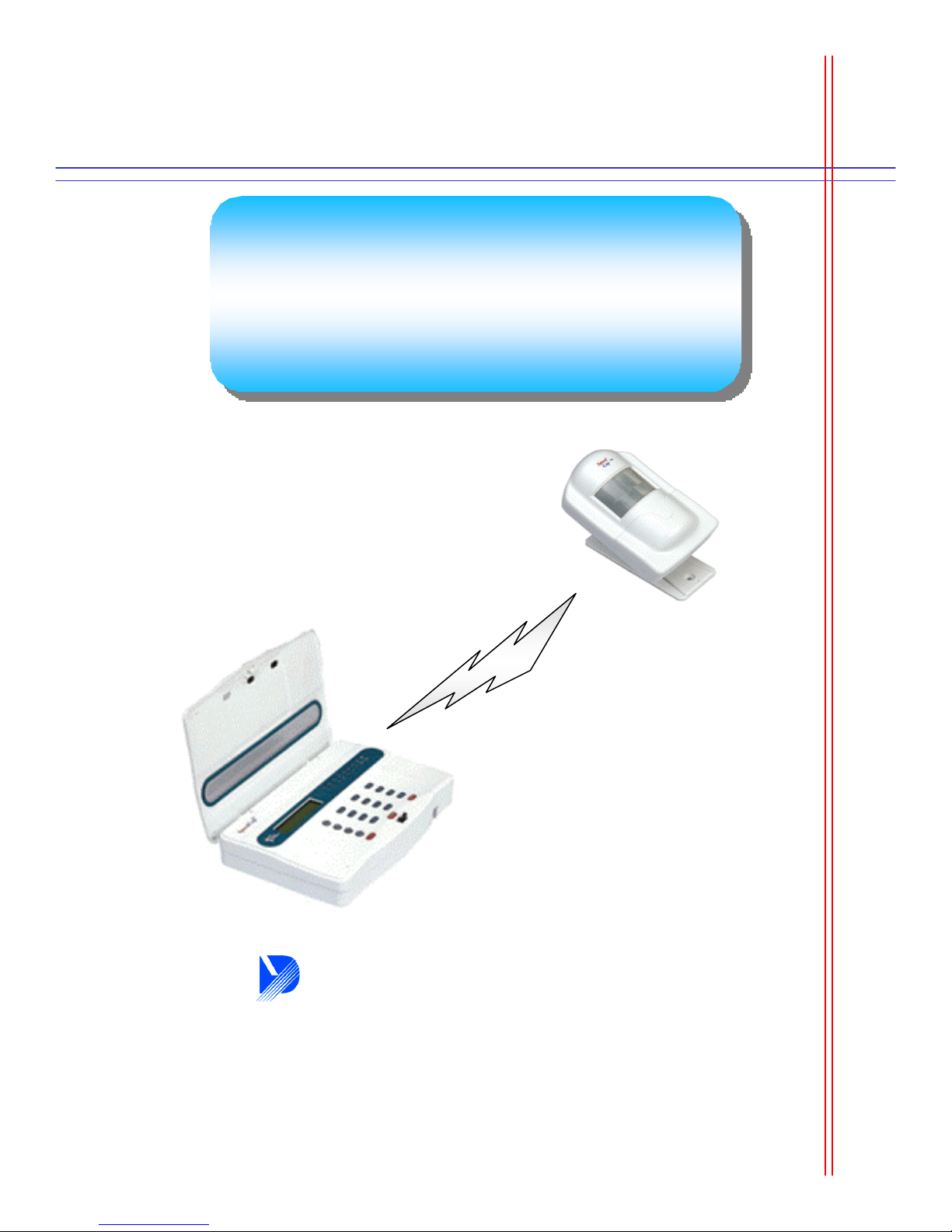
FM Wireless Home Security
FM Wireless Home Security
Alarm System
Alarm System
TM
- SpeedCop
- SpeedCop
TM
2000-
2000-
Dynamic Technology Inc.
www.dynamictek.com
Page 2

Index
SpeedCop
TM
2000
Description
Standard Scope of Supply 2
Option 3
Layout
Layout -Front 4
Layout -Rear 6
Operating flow 8 Special Function
Installation Guide Bypass & Delay Time 23
Order of installation 9
Page(s)
Description Page(s)
Voice Recording 18
Exit 19
Siren ON/OFF 20
Input(Overall) 21
Arming & Disarming 22
Chime Function 24
Power and Sensors 10
Main Body, PIR/Door Sensors 11 Remote Control 25
Input
Attention & Request 12
Remote Controller 13
Sensors 14
Telephone Number 15
Emergency Call 16
Password 17
PIR Sensor & Remote Controller 29
RF Transmitter & Door Sensor 30
WARNING Notice: Please Read Carefully 31
ARS Structure
Remote Control Code 26
Guide of emergency meeting 27
Power & Tel.Line cut off 28
Sensor Feature
Dynamic Technology Inc.
1
Page 3
Standard Scope of Supply
SpeedCop
TM
2000
Division
B
A
S
I
C
I
T
E
M
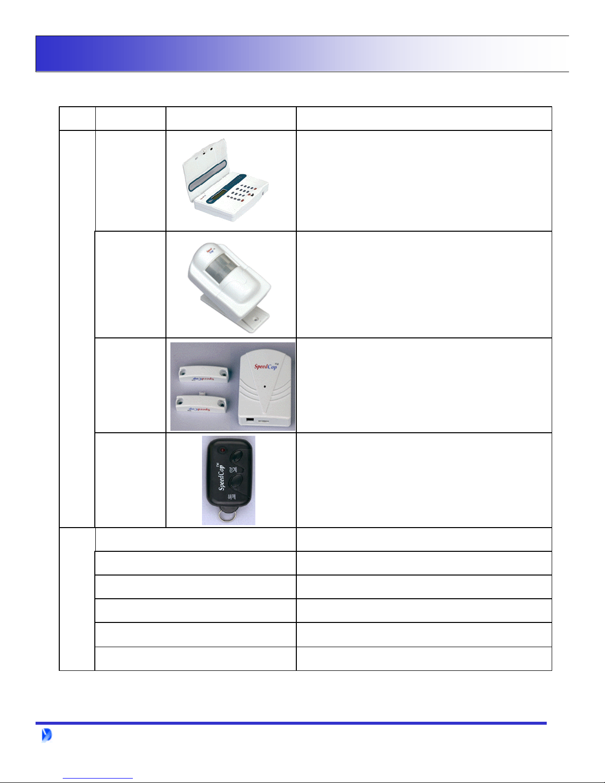
ITEM Appearance Specification
Power Supply Unit : DC9V Battery, 600mA
Power Consumption : Disarms(150mA), Arms(300mA)
Max. Sensor No. : 7 Wireless + 2 Wire
Main Body
PIR Sensor
Door Sensor
Max. Remote control No. : 7 units
Max. recording No. of Telephone : 7
Demodulation Method : Frequency Demodulation
Dimensions : 47D x 144H x 222W
Power : DC 9V Battery
Transmission & Reception Method : Radio Frequency
Modulation Method : Frequency Modulation
Detection Method : Passive Infrared
Angle : Vertical(45), Wide(110 )
Communication Distance : Max. 1000M Detection Range : Max.30M
Dimension : 32D x 97H x 65W
Composition : 2 Magnetic Bars + 1 RF Transmitter
Detection Method : Magnetic
Remote
controller
A
C
C
E
T - Hanger
Warning Decals
S
S
O
R
Y
Phone cable
User Manual
Dynamic Technology Inc.
Adapter
Battery
Composition : 2 Buttons(ON + OFF)
Communication Method : Radio Frequency(FM Wave)
Utility Range : 50M Dimensions : 30mm x 11mm x 55mm
Battery Power : DC 12V(A23 Alkaline Battery)
Power supply unit to main body at DC 9V
When the main body is hanging on the wall
Sticking an invasion route for warning
Supply ; the power to PIR sensor & RF transmitter
Connector between the main body and local telephone
Utility Guide for SpeedCop2000
2
Page 4
Option
SpeedCop
TM
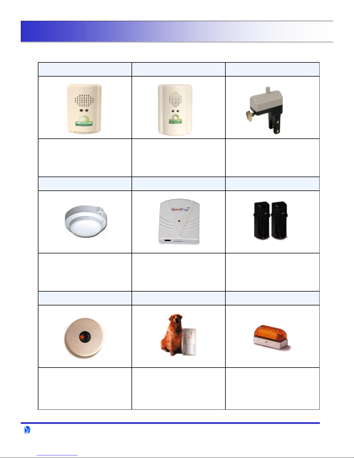
Gas Detector Gas Controller Gas Shut off Devise
2000
Detection Method : Contact Combustion
Response Speed: Within 20 Sec.
Detects LNG & LPG, Butane/Methane Gas
Power : AV 220V, 50/60Hz
Power Consumption : 2.7W
Dimensions : 46D x 116H x 66W
Power : AV 110/220V(60Hz)
Power Consumption : 1.3W
Output Voltage : DC12V
Operating Temperature : -10 ~+40
Relative Humidity : 20 ~ 95% RH
Dimensions : 44D x 145H x 100W
Valve : Screw Type(Ball Valve)
Power : DC12V
Power Consumption : 2.5W
Shut-off Speed : 5 Sec.
Dimensions : 118D x 167H x 60W
Fire Detector RF Module Infrared Detector
Modulation : Frequency Modulation
Frequency Bandwidth : 447.275MHz
Power : DC 9V
Application Field : Gas, Door & Fire Detector
dimensions :
PIR Sensor(Ceiling style) Pet Detector Light
Detection technology : Dual Element PIR
Current Consumption : 15mA at DC 12V
Power : DC 9~16V regulated
Alarm Contact : DC 24V, 50mA
Pulse Count : Selectable 1~3
RF Immunity : 3-V/m. up to 1GHz
Dynamic Technology Inc.
Current Consumption : 25mA at DC 12V
45MA at DC 16V
Voltage Requirements : DC 9-16V regulated
Alarm Contacts : DC 24V, 50mA
Temper Contacts : DC 24V, 0.1A
Power Supply : DC12V
Power Consumption : 120mA
Natural Gifts : Cover - Acrylic
Base - ABS
Dimensions : 26mm x 167mm x 96mm
3
Page 5
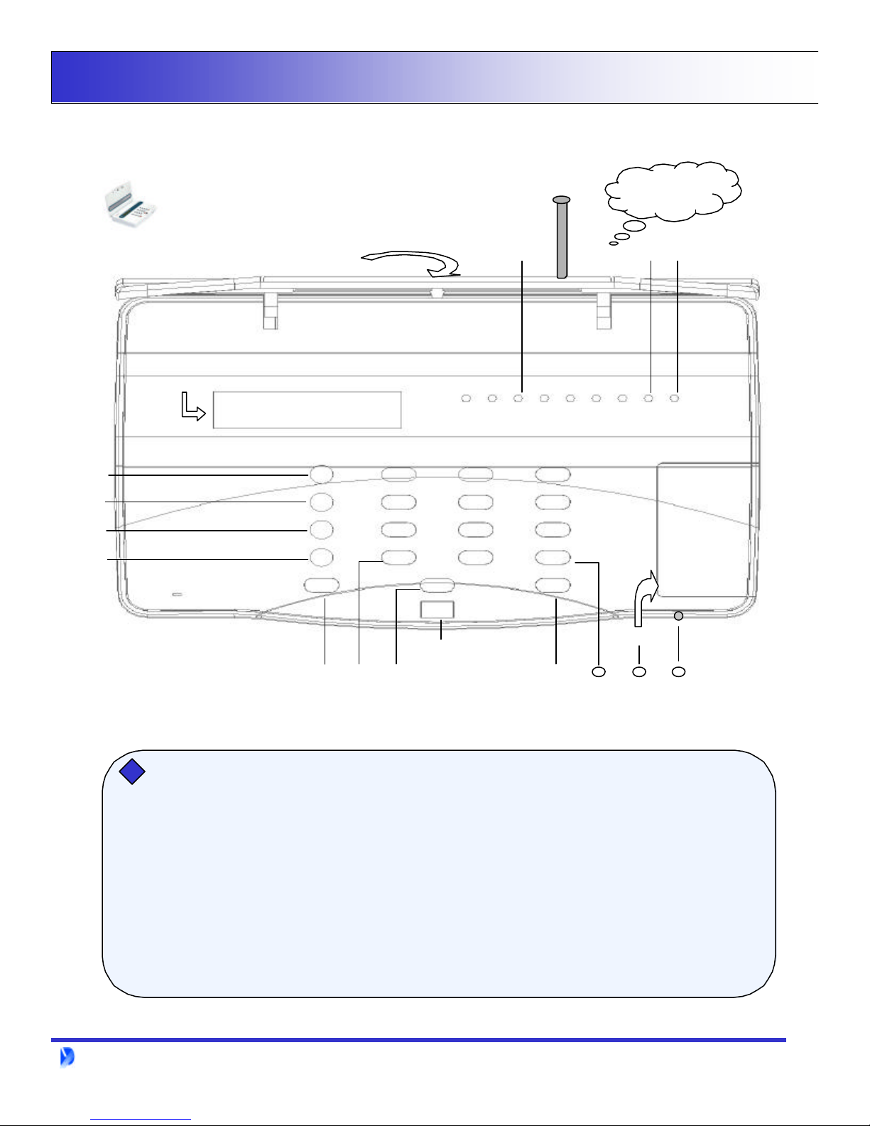
Layout - Front
Main Body(Front)
SpeedCop
The front cover is opened
TM
2000
Front Cover
Antenna
LCD(Liquid Crystal Display)
1 2 3 4 5 6 7
Army
DisArm
Bypass
Alarm
911
1 2 3
4 5 6
7 8 9
*
Ambulance Police
Cover : Close / Open
0
#
ARM POWER
9V Alkaline Battery
Cut off the powerCut off the power
If the main power is cut off, the main body can operate itself by DC 9V alkaline battery continuously.
Power LED changes to a green color and other LED’s are off if the main body is supplied with power by the backup battery.
In this case, user may be confused that each sensor does not operate as the back light of LCD can not operate. But, sensors are
normally operated due to save the battery.
* You must use DC 9V alkaline battery as a backup battery
* Max. time : 6 hours
Dynamic Technology Inc.
18
16 17
4
Page 6

Layout - Front
1. Front Cover : Main body cover of SpeedCopTM2000
2. Arming LED : Per each sensors Red light shows when the sensoris armed
3. Antenna : Receiving the FM signal of each sensors
4. Arming LED : Classification of Arming or Disarming
5. Power : Checking of power ON/OFF(Yellow light)
6. LCD(Liquid Crystal Display) : Showing the order or input text on the LCD
7. Arm : Arming of all the sensors.
SpeedCop
TM
2000
8. Disarm : Disarming of all the sensors.
9. Bypass : Bypass the selected sensors by user ’s requirement.
10. Chime : Automatic alarm notice is arming if the door is not completely closed and
chime bell sound when Disarming mode of the main door sensor .
11. 911(Emergency call) : Automatic call to 911 by one-touch button
12. Key : Cancellation Key
*
13. Ambulance : Emergency calling function to memorized hospital by one-touch button
14. Cover Open/Close : SpeedCop 2000 cover open/close
15. Police : Emergency calling function to memorized police station by one-touch button
16. Key : Enter Key
#
17. DC 9V battery : Spare battery when the main power is cut off
18. MIC. : Tapping or dual-communication function through MIC. from the outside
Dynamic Technology Inc.
5
Page 7
Layout - Rear
Main Body(Rear)
SpeedCop
TM
2000
X
X
X
X
X
X
X
X
X
X
Rear Terminal
You can use wire sensors usually.==> You may use additional wiresensors.
1. External Lamp : Notice emergency to outside by light
2. External Siren : Notice emergency to outside by siren
3. Impact Detector : Install at windows for detecting intruder
4. Infrared Detector : Installing both sides of intruding route and detector sensing when intruder passes through this route
5. Fire Detector : Detecting fire and smoke
6. Gas Detector & Shut-off Device : Gas shut off equipment with remote controller from outside
Dynamic Technology Inc.
6
Page 8

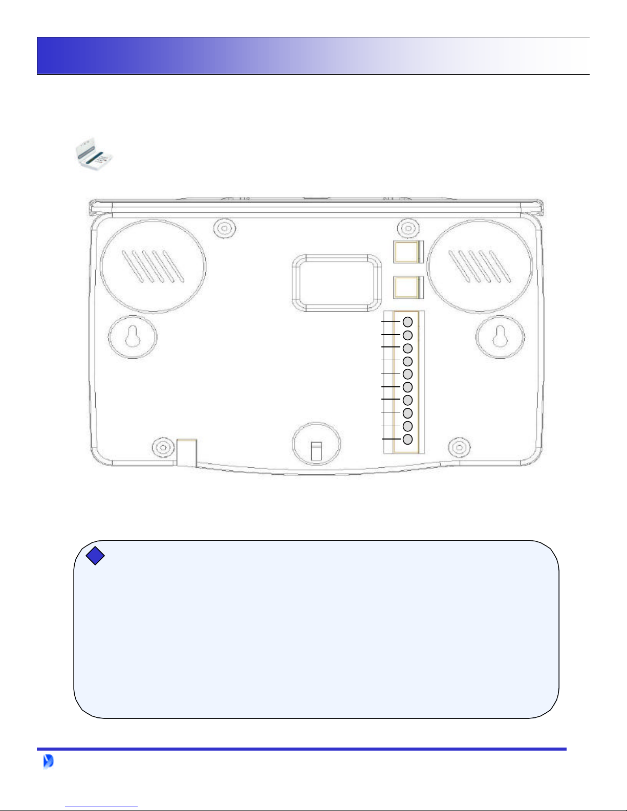
Layout - Rear
1. Speaker : For siren, ARS comment or key tone.
2. Telephone port : Connecting port between the main body and te lephone
3. Line port : Connecting port to main body from the line of the telephone office
4. T Hanger : Use when the main body is hanging on the wall
5,6. Telephone line terminal : Connecting to Line port No.3 or telephone line terminal which comes from
telephone office line
SpeedCop
TM
2000
7. Output A : The first output terminal for controlling sensors or siren at the main body
8. Common : Common terminal of external output terminal A & B
9. Output B : The second output terminal for controlling sensors or siren at the main body
10. Input A : The first input terminal for transmission of signal from sensors to main body
11. Common : Common terminal of external input terminal A & B
12. Input B : The second input terminal for transmission of signal from sensors to main body
13. GND : DC 9V power ground terminal
14. DC power terminal : DC 9Vpower terminal
15. DC power terminal : DC 9Vpower terminal(for Adapter)
Dynamic Technology Inc.
7
Page 9
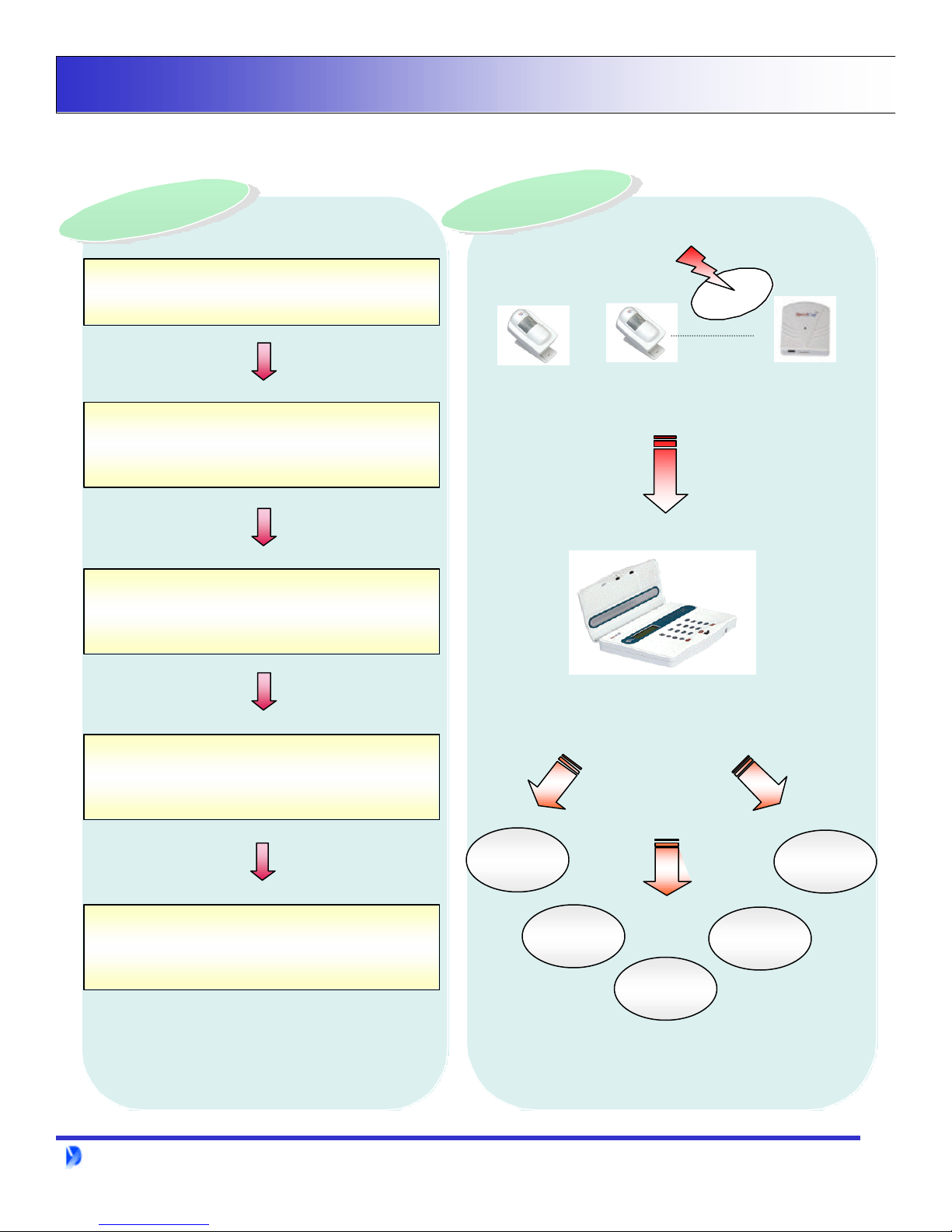
Operating Flow
Chart
Chart
-
-
Chart
Chart
-
-
Flow
Flow
Flow
Flow
Intruder
Intruder
Intruder
Intruder
SpeedCop
TM
2000
Intruders & Emergency
Automatic Dialing to the personal Cellular Phone
or other designated destination
(7 Memorized Telephone Numbers)
Tapping and checking by sounds
from the outside
Intruders
Sensor #1 Sensor #2 Sensor #7
FM TransmissionFM Transmission
(1 Km Direct Distance)(1 Km Direct Distance)
Emergency CallEmergency Call
PSTN : Local Telephone
Controlling of the intruder with Siren
and arms(Option)
Call to related office or neighbor for help.
Dynamic Technology Inc.
#1
PCS
C/Phone
Neighbors
Memorized 7
Phone No.
Related
Office
Company
8
Page 10

Installation Guide- Order of installation
1. Check the position of Main body & Sensors1. Check the position of Main body & Sensors
-- Considering the position of main power & telephone lineConsidering the position of main power & telephone line
2. Unpacking the SpeedCop 20002. Unpacking the SpeedCop 2000
3. Connecting the telephone line and the power to the Main Body3. Connecting the telephone line and the power to the Main Body
-- Main Power : for DC 9V(adapter)Main Power : for DC 9V(adapter)
SpeedCop
TM
2000
4. Input the telephone numbers, set up sensors and remote 4. Input the telephone numbers, set up sensors and remote
controller.controller.
5. Connecting each sensors to input & output terminal5. Connecting each sensors to input & output terminal
-- ex : Gas detector, siren, wire sensor, etc.(Picture 2)ex : Gas detector, siren, wire sensor, etc.(Picture 2)
6. Re6. Re--checking input result and test operationchecking input result and test operation
7. Fixing and hanging main body & each sensors7. Fixing and hanging main body & each sensors
Dynamic Technology Inc.
Installation Completed
Installation Completed
9
Page 11

Installation Guide- Power & Sensors
Connecting of Power & Telephone lineConnecting of Power & Telephone line
DC 9V
SpeedCop
Telephone Line
Telephone Office
Line
TM
2000
Connecting of SensorsConnecting of Sensors
Telephone line
IN
Output 1
Output Com
Output 2
Input 1
Input Com
Input 2
GND
DC 12V
AC 110V, 60Hz
Other
wire sensors
Siren
controller
Gas
Gas Parts
Gas
Breaker
Dynamic Technology Inc.
Picture 2
10
Page 12

Installation Guide- Main Body, PIR/Door Sensor
Main Body Main Body (For attaching on the wall)(For attaching on the wall)
Setting up T-tag on the wall
Hanging the Main body at the three points of the T-tag
PIR SensorPIR Sensor
SpeedCop
TM
2000
0
45
Door SensorDoor Sensor
Distance: about 8 meter
1. The position of PIR sensor is suitable opposition side from door
or intrusion route
2. Please install PIR sensor after setting up sensors.
Magnetic Bar
RF Transmitter
Within 1Cm
1. Not more than 1Cm between the two
magnetic bars
Dynamic Technology Inc.
11
Page 13

Input - Attention and Reset
Input set up is being done when in disarming mode only
If you want to cancel inputting information while you input, please enter asterisk key
Use reset for deletion purpose only
Keypad LCD(Liquid Crystal Display)
Remote Controller
Remote Controller
Reset
Reset
Resetting of the first remote controller
SpeedCop
SpeedCop 2000
TM
2000
1.
2.
4.
Sensor Reset
Sensor Reset
4.
3. Press the key
Press the number key
Press the number again
(The second remote controller is )
Press the Key
Press the Key again
#
#
1
1
This procedure deletes the previous input record
Resetting the third Sensor
#
Key
Press the number1.
Press the number2.
#
2
3
2
ARS Comment
ARS Comment
Menu Input : 1
*
Menu Input : 11
*
Remote controller Setup : 13.
Input completed
SpeedCop 2000
Menu Input : 2
*
Menu Input : 23
*
Sensor Setup #3
4. Press the key again
Dynamic Technology Inc.
#
This procedure deletes the previous third input record
ARS Comment
Input completed
12
Page 14

Input - Remote Controller
* Input set up is being done when in disarming mode only
Input code number
Input code number
Division Input Code Division Input Code
Remote Controller 11 ~ 17 Password 51
SpeedCop
TM
2000
Sensor (1)21 ~ (1)27
Telephone Number 31 ~ 37
Emergency Call 41 ~ 43 Exit 71
Remote controller
Remote controller
2.
Recording of User’s comment
Replaying of the user’s comment
Keypad
Press the number1. *1
Press the number again
(The second remote controller is number )
1
2
61
62
(*Siren On/Off : 81)
LCD(Liquid Crystal Display)
SpeedCop 2000Input the first Remote controller
Menu Input : 1
Menu Input : 11
*
3. Press the Key#
Dynamic Technology Inc.
Remote controller setup : #1
Press the arming button4.
ARS Comment
Input Completed
13
Page 15

Input - Sensors
Sensors
Sensors
SpeedCop
TM
2000
Keypad LCD(Liquid Crystal Display)
SpeedCop 2000Input of the first sensor
2.
4.
1.
Press the number Key
Press the number Key
(The second sensor No. : )
#
Put the battery into a sensor or sensing
PIR Sensor(Has to show red light at the sensor)
- Connecting the battery to sensor
- Waiting 10 seconds till next sensing
Door Sensor
- Put the battery into RF Transmitter while RF transmitter of door sensor and magnetic bars
are connected
2
1
2
ARS Comment
Menu Input : 2
*
Menu Input : 21
*
Sensor Setup #1 3. Press the Key
Input completed
* Add sensors as a customer ’s requirement(PIR, Door, Fire, Gas sensor, etc.
- Wireless : Add up to 7 sensors(LED) by serial and unlimited if connected by parallel
- Wired : Add up to each 2 sensors for input and output(Gas, Fire, Siren, Light, etc.)
BypassBypass
Bypass
Arming or disarming of appointed sensors among installed sensors by user ’s
requirement.
1 +
Dynamic Technology Inc.
21+
+ +
Sensor detecting
#
Set up the sensor No. 1 : Bypass
14
Page 16

Input - Telephone Number
Keypad LCD Display
Telephone Number
Telephone Number
Input the first Telephone number
SpeedCop
SpeedCop 2000
TM
2000
1.
2.
3.
4.
5.
* If you want to input additional telephone numbers, please change numbers 2 & 4 only.
* Telephone number can be input up to 7numbers.
* Caution :Although the number is repeat, please input all of 7 telephone number.
Press the number key
Press the number key
- The second telephone number :
Press the Key
Please input the first telephone number(ex : 323-2680)
Press the Key
#
#
2
1
2
Menu Input : 3
*
Menu Input : 31
*
Tel. Number : 1
7806890
ARS Comment
Input completed
Confirming
Confirming
Telephone number
Telephone number
1 3 1
+1.
2. Press the Key
code.
Dynamic Technology Inc.
SpeedCop 2000Confirming the first telephone number
+
#
1* If you want to confirm the additional telephone number, please input before you press the telephone input
Menu Input : 131
*
7806890
15
Page 17

Input - Emergency Call
Keypad LCD(Liquid Crystal Display)
Emergency
Emergency
call number
call number
SpeedCop
TM
2000
SpeedCop 2000Input the first emergency call number
4Press the number Key1.
2.
3.
4.
5.
* If you want to input additional numbers, please change numbers 2 & 4
* Please input the number of emergency station that is near wher e you are
Press the number Key
Press the Key
Please input the first emergency call number(ex : 911)
Press the Key
#
#
1
Menu Input : 4
*
Menu Input : 41
*
Emergency Tel #1
911
ARS Comment
Input Completed
Confirming
Confirming
the number
the number
1 4 1
+1.
2. Press the Key
* If you want to confirm the additional telephone number, please input before you press the telephone input
code.
Dynamic Technology Inc.
SpeedCop 2000Confirming the first number
+
#
1
Menu Input : 141
*
911
16
Page 18

Input - Password
Password
Password
SpeedCop
TM
2000
Keypad LCD(Liquid Crystal Display)
SpeedCop 2000Input of Password
1. Press the number Key
2. Press the number Key
3. Press the number Key
4.
5. Press the Key Input Completed
Please input 4 digit password
#
5
1
#
Menu Input : 5
*
Menu Input : 51
*
Password :
*
Password : 1234
*
ARS Comment
In this case, needing passwordIn this case, needing password
- Control the main body with remote control from outside by telephone.
- When user wants to “Bypass”.
- When user touch any key on the main body under Arming.
In this case, The main body requests password.
Dynamic Technology Inc.
17
Page 19

Input - Voice Recording
Keypad LCD(Liquid Crystal Display)
Recording Voice
Recording Voice
SpeedCop
SpeedCop 2000Voice Recording
TM
2000
2.
3.
4.
Replay
Replay
Press the number Key1.
Press the number Key
Press the Key
The main body will start recording warning message for 12 seconds
#
6
1
Menu Input : 6
*
Menu Input : 61
*
Recording : 12
*
SpeedCop 2000Replay of recorded voice
1.
2. Press the number Key
3. Press the Key
4.
Dynamic Technology Inc.
Recorded voice message will replay through speaker for 12 seconds
Press the number Key
6
2
#
Menu Input : 6
*
Menu Input : 62
*
Play : 12
*
18
Page 20

Input – Delay Time
Keypad LCD(Liquid Crystal Display)
Delay Time
Delay Time
SpeedCop
SpeedCop 2000Input Exit time
TM
2000
Press the number Key1. Menu Input : 7
2. Press the number Key Menu Input : 71
3. Press Key Delay Time :
#
7
1
*
*
*
4. Delay Time : 15
5. Press the Key
* Exit time that you go out from home to outside.
* Suitable setting time :10 ~ 15 seconds
Dynamic Technology Inc.
Input the interval time you wanted (ex : 15 seconds)
*
#
ARS Comment
Input Completed
19
Page 21

Input - Siren On/Off
Keypad LCD Display
Siren
Siren
SpeedCop
TM
2000
Siren ON/OFF
Press the number Key1. Menu Input : 8
2. Press the number Key Menu Input : 81
3. Press the Key Siren : ON
#
8
1
SpeedCop 2000
*
*
*
4.
5.
Dynamic Technology Inc.
Please press any number key( ~ )
The main body is changed
from on(off) to off(on) automatically.
Press the Key
91
#
Siren : OFF
*
ARS Comment
Input completed
20
Page 22

Input - overall
Key Function : (* : Cancel, # : Enter)
SpeedCop
TM
2000
Remote
Controller
Sensor
No. K e y p a d ARS Comment
1 Input completed
2 Input completed
3 Input completed
4 Input completed
5 Input completed
6 Input completed
7 Input completed
1 + + + Sensor No.1 : Power approval Input completed
2 + + + Sensor No.2: Power approval Input completed
3 + + + Sensor No.3 : Power approval Input completed
4 + + + Sensor No.4 : Power approval Input completed
5 + + + Sensor No.5 : Power approval Input completed
6 + + + Sensor No.6 : Power approval Input completed
7 + + + Sensor No.7 : Power approval Input completed
1 + + + Telephone No.1 + Input completed
+ + Remote controller No.1 : ON
1 1
+ + Remote controller No.2 : ON
1 1
1 2 #
1 3 #
1 1
+ + Remote controller No.3 : ON
1 4 #
+ + Remote controller No.4 : ON
1 5 #
+ + Remote controller No.5 : ON
+ + Remote controller No.6 : ON
1 6 #
1 7 #
+ + Remote controller No.7 : ON
1
2
2
2
3
2
4
2
5
2
6
2
7
2
1
3
#
#
#
#
#
#
#
#
#
#
Remarks
Remote controller
: 10 units
In Bypass case :
Input key
1
before you press
key
2
Telephone
Number
Emergency
Telephone
Number
Input of
Password
Voice
Recording
Stay
2 + + + Telephone No.2 + Input completed
3 + + + Telephone No.3 + Input completed
4 + + + Telephone No.4 + Input completed
5 + + + Telephone No.5 + Input completed
6 + + + Telephone No.6 + Input completed
7 + + + Telephone No.7 + Input completed
1 + + + Telephone No.1 + Input completed
2 + + + Telephone No.2 + Input completed
3 + + + Telephone No.3 + Input completed
1 + + + Enter password Input completed
1 + + + Recording Recording time indicated
2 + + + Reply Reply indicated
1 + + + (0~99 seconds) + Input completed
2
3
3
3
3
3
3
4
4
4
1 #7 #
#
3
#
4
#
5
#
6
#
7
#
1
#
2
#
3
#
1 #5
1 #6
2 #6
#
#
#
#
#
#
#
#
#
)
(Ex.)
1
3 1 #
+ + +
Input the number
of 911, police,
ambulance,etc.
(****)
12 seconds
Dynamic Technology Inc.
21
Page 23

Arming & Disarming
SpeedCop
TM
2000
ARS Comment
Arming Completed
Arming
Arming
All sensors armed
Disarming
Disarming
Converting from Arming to disarming mode
ARS Comment
Disarming Completed
Time Out : 15
*
1 2 3 4 5 6 7 Aem Power
Green LED
is flicker
1 2 3 4 5 6 7 Arm Power
Only power LED is On
in standby mode
Dynamic Technology Inc.
22
Page 24

Arming & Disarming – manual use
Arming & Disarming
Arming & Disarming
After arming, delay time in order to go out from
Operating appointed sensors by user only
inside to outside(0~99 seconds).
SpeedCop
Delay Time
Delay Time
TM
2000
Arming or
ARS Comment
Dis-
arming
Enter password
Password : 1234
*
ARS Comment
Arming/Disarming Completed
Time Out : 15
*
Push the number “71”
Delay Time :
*
Delay Time : 15
*
#
ARS Comment
Input Completed
Sensor 1 and 3,5,7
are armed
1 2 3 4 5 6 7 Arm Power
Bypass FunctionBypass Function
Bypass : User select specific sensor and then register at the main body, so the specified sensors are armed. .
Dynamic Technology Inc.
Arm led is flicker
* Exit time: 0 ~ 99 seconds
* Suitable Exit time : 10 ~ 15 seconds
23
Page 25

Special Function - Bypass & Alarm
SpeedCop
TM
2000
Bypass
Bypass
Operating appointed sensors by user only
Bypass
ARS Comment
Enter password
Password : 1234
*
ARS Comment
Arming Completed
If doors or windows are open,
the main body informs the fact
In case third door sensor is opened
ARS Comment
Chime
Chime
The Third LED flickers
Chime
A door is opened
Time Out : 15
*
Chime FunctionChime Function
1.You can confirm if a door or window is open / close in a zone when you are out.
2.You can use chime bell function by push the Chime button when disarming mode.
Dynamic Technology Inc.
Sensor 1 and 3,5,7
are armed
1 2 3 4 5 6 7 Arm Power
Arm led is flicker
Door Sensor #3
*
Close the door or the window
24
Page 26

ARS Structure - Remote Control
SpeedCop
TM
2000
Repeat twice
Arming of SpeedCop
Sensing intruder.
Sensing gas leakage
Sensing fire.
User Comment
User Comment
To listen again press “0”
To listen again press “0”
Connecting from outside
Arming mode : Control after ringing 3 times
Arming, Disarming & Bypass mode
: Control after ringing 8~9 times
Enter Password
Enter Password
No
Yes
Calling code number is “50”, arming number is “10”
disarming number is “20” to end press “star”key
Password incorrect,
Password incorrect,
enter password again
enter password again
Calling code number is “50”, arming number is “10”
disarming number is “20” to end press “star”key
To listen again press “0”
To listen again press “0”
Dynamic Technology Inc.
To listen again press “0”
To listen again press “0”
Order performance
Order performance
25
Page 27

ARS Structure - Remote Control Code
SpeedCop
TM
2000
10
Arming
- Keeping main body on arming mode
by remote control or push arming
button.
50
Both side
- Hearing footsteps, sound or whisper etc.
- Shout to intruder out
- end of emergency by remote control
when sensing the family
20
Disarming
- Keeping main body on disarming mode
by remote control or push Disarming
button.
Example : when the main body senses
the intruder is not a burglar.
*
E N D
- This command stops the main body from
calling the next telephone number.
30
Output A control
- The siren included in the main body rings
by remote control
- operate wired equipment connected output
to terminal A
60
Output B control
- Operate wired equipment connected output
terminal B
(Ex : Gas controller, Outdoor siren etc.)
40
Output A disarming
- The siren included in the main body is
turned off by remote control
- stop operating wired equipment connected
output terminal A
70
Output B disarming
- stop operating wired equipment connected
output terminal B
Dynamic Technology Inc.
26
Page 28

Guide of emergency meeting
User must control by phone to meet emergency after receiving telephone
Sensing Controlling
SpeedCop
TM
2000
Intruder
Sensing
Fire
Sensing
Tapping (50)
Ring a siren (30)
Turn off the siren (40)
Tapping (50)
Ring a siren (30)
Shut off the Gas (60)
Listen to the ARS comment that a intruder is detected and then
check whether it is family or intruder
Threaten the intruder by siren & call the police
Listen to the ARS comment that a fire is detected
Spread to neighbors with ringing siren and then
call the fire station immediately
Listen to the ARS comment that gas is detected &
input the code “60” for shutting off the gas panel
Checking gas siren (50)
Gas
Turn off the Gas(70)
Sensing
Emergency Completion(*)
Dynamic Technology Inc.
Check the gas stop
Turn off the gas panel for rechecking
Input the remote control code for arms and then
emergency is completed
*
27
Page 29

Power & Tel. Line Cut Off
Cutting off of main power
Coming from DC 9V battery at the main body
Appearance
- Power LED changes from yellow to green
- Light of LCD is off
* Most function is the same as before.
* Back up battery : DC 9V Alkaline battery only(Duration : about. 6 hours)
Cutting off of telephone line
1. Arming(Includes Stay function)
SpeedCop
TM
2000
ARS Comment
Please connect telephone line
2. Sensing after arming :
Ringing Siren
Battery dischargingBattery discharging
Sensor or battery shows changing time of battery before back upbattery discharge
1. Battery of main body
ARS Comment
2. Battery of Sensor
Please change battery
Enter button
Enter Button
* *
Main Low Bat
ARS Comment
Please change battery
Dynamic Technology Inc.
Low Bat Sensor #3
28
Page 30

Sensor Feature - PIR Sensor/Remote controller
PIR Sensor
PIR Sensor
• FM (Frequency Modulation) Type - Increasing of communication
distance
•PIR sensing function
•Sensing distance : Approx.. 10M ~ 20M
• Communication distance : about 1Km
• Detecting Angle
Wide angle : 110 Vertical angle : 45
SpeedCop
TM
2000
• Automatic notice of low voltage
- Life cycle of battery : 6 months at least
Remote controller
Remote controller
• Arming & Disarming function
• Stay : Press the Arming & Disarming button at the same time
• Emergency Call : Press arming button for 3 seconds at least
• Automatic notice of low voltage
• Communication distance : about.50M
Dynamic Technology Inc.
29
Page 31

Sensor Feature - RF transmitter & Door sensor
RF Transmitter
RF Transmitter
Radio Frequency Transmitter
• FM (Frequency Modulation)Type - Increasing the communication
distance
• For door sensor, Gas sensor, Fire sensor
• Communication distance : about. 1Km direct distance
• Notice of low voltage
• Life cycle of battery : Min. 6 months
• Adapter : DC 9V available
SpeedCop
TM
2000
• RF transmitter & sensors :Wire
DIP Switch control
Dismantle 2 pieces of screw on PCB after opening the rear cover of RF Transmitter
Control the dip switch of IC
Door Sensor Fire Sensor Gas Sensor
ON ON ON
Intruder detected Fire detected Gas detected
Door Sensor
Door Sensor
• When sensor is operating magnetic bars on doors / windows come off
• Use together with RF transmitter
• Magnetic bar operates a magnet principle
Dynamic Technology Inc.
30
Page 32

WARNING Please Read Carefully
SpeedCop
Note to Installers
This warning contains vital information. As the only individual in contact with system users, it is your responsibility to
bring each item in this warning to the attention of the users ofthis system.
System Failures
This system has been carefully designed to be as effective as possible. There are circumstances, however, involving fire,
burglary, or other types of emergencies where it may not provide protection. And alarm system of any type may be
compromised deliberately or may fail to operate as expected for a variety of reasons. Some but not all of these reasons
may be:
Note : The manufacture is not responsible for any radio or TV interference caused by unauthorized modifications to this
equipment. Such modifications could void the user ’s authority to operate the equipment.
Inadequate Installation
A security system must be installed properly in other to provide adequate protection. Every installation should be
evaluated by a security professional to ensure that all access points and areas are covered. Lock and latches on
windows and doors must be secure and operate as intended. Window s, doors, walls, ceilings and other building
materials must be of sufficient strength and construction to provide the level of protection expected. A reevaluation
must be done during and after any construction activity. An evaluation by the fire and/or police department is highly
recommended if this service is available.
Criminal Knowledge
This system contains security features which were known to be ef fective at the time of manufacture. It is possible for
persons with criminal intent to develop techniques which reduce the effectiveness of these features. It is important
that a security system be reviewed periodically to ensure that its features remain effective and that it be updated or
replaced if it is found that it does not provide the protection expected.
Access by Intruders
Intruders may enter through an unprotected access point, circumvent a sensing device, evade detection by moving
through an area of insufficient coverage, disconnect a warning device, or interfere with or prevent the proper operation
of the system.
Power Failure
Controllers, intrusion detectors, smoke detectors and many other security devices require an adequate power supply
for proper operation. If a device operates from batteries, it is possible for the batteries to fail. Even if the batteries have
not failed, they must be charged, in good condition and installe d correctly. If a device operates only by AC power, any
interruption, however brief, will render that device inoperative while it does not have power. Power interruptions of
any length are often accompanied by voltage fluctuations which may damage electronic equipment such as a security
system. After a power interruption has occurred, immediately conduct a complete system test to ensue that the system
operates as intended.
Failure of Replaceable Batteries
This system’s wireless transmitters have been designed to provide several months of battery life under normal
conditions. The expected battery life is a function of the device environment, usage and type. Ambient conditions such
as high humidity, high or low temperatures, or large temperature fluctuation may reduce the expected battery life.
While each transmitting device has a low battery monitor which identifies when the batteries need to be replaced, this
monitor may fail to operate as expected. Regular testing and maintenance will keep the system in good operating
condition.
Compromise of Radio Frequency (Wireless) Devices
Signals may not reach the receiver under all circumstances which could include metal objects placed on or near
the radio path or deliberate jamming or other inadvertent radio signal interference.
TM
2000
31
Page 33

WARNING Please Read Carefully
.
System Users
A user may not be able to operate a panic or emergency switch possibly due to permanent or temporary physical
disability, inability to reach the device in time, or unfamiliar ity with the correct operation. It is important that all system
users be trained in the correct operation of the alarm system and that they know how to respond when the system
indicates
an alarm.
Motion Detectors
Motion detectors can only detect motion within the designated ar eas as shown in their respective installation instructions.
They cannot discriminate between intruders and intended occupants. Motion detectors do not provide volumetric area
protection. They have multiple beams of detection and motion can only be detected in unobstructed areas covered by
these beams. They cannot detect motion which occurs behind walls, ceilings, floor, closed doors, glass partitions, glass
doors or windows. Any type of tampering whether intentional or unintentional such as masking, painting, or spraying
of any material on the lenses, mirrors, windows or any other par t of the detection system will impair its proper operation.
Passive infrared motion detectors operate by sensing changes in temperature. However their effectiveness can be
reduced when the ambient temperature rises near or above body temperature or if there are intentional or unintentional
sources of heat in or near the detection area. Some of these heat sources could be heaters, radiators, stoves, barbecues,
fireplaces, sunlight, steam vents, lighting and so on.
Warning Devices
Warning devices such as sirens, bells, horns, or strobes may not warn people or waken someone sleeping if there is an
intervening wall or door. If warning devices are located on a different level of the residence or premise, then it is
less likely that the occupants will be alerted or awakened. Audible warning devices may be interfered with by other
noise sources such as stereos, radios, televisions, air conditioners or other appliances, or passing traffic. Audible
warning devices, however loud, may not be heard by a hearing-impaired person.
Telephone Lines
If telephone lines are used to transmit alarms, they may be out of service or busy for certain periods of time. Also an
intruder may cut the telephone line or defeat its operation by more sophisticated means which may be difficult to detect.
Insufficient Time
There may be circumstances when the system will operate as intended, yet the occupants will not be protected from
the emergency due to their inability to respond to the warnings in a timely manner. If the system is monitored, the
response may not occur in time to protect the occupants or theirbelongings.
Component Failure
Although every effort has been made to make this system as reliable as possible, the system may fail to function as
intended due to the failure of a component.
Inadequate Testing
Most problems that would prevent an alarm system from operating as intended can be found by regular testing and
maintenance. The complete system should be tested weekly and immediately after a break-in, an attempted break-in,
a fire, a storm, an earthquake, an accident, or any kind of cons truction activity inside or outside the premises. The
testing should include all sensing devices, keypads, consoles, alarm indicating devices and only other operational
devices that are part of the system.
Security and Insurance
Regardless of its capabilities, an alarm system is not a substitute for property or life insurance. An alarm system also
is not a substitute for property owners, renters, or other occupants to act prudently to prevent or minimize the harmful
effects of an emergency situation.
SpeedCop
TM
2000
32
 Loading...