

Page 1

SFC332L
OPERATORS MANUAL
Flow C o m p u t e r
Liqui d V e r s i o n
11 1 0 4 W . A i r p o rt Blvd , S u i t e 1 0 8 & 1 4 8
Staf f o r d , T e x as 77 4 7 7 U S A
(2 81 ) 5 6 5 -1118
Fa x ( 2 8 1 ) 5 6 5 -11 1 9
Date: 8/1/2019
Page 2

WARRANTY
Dynamic Flow Computers warrants to the owner of the Smart Flow Computer that the
product delivered will be free from defects in material and workmanship for one (1) year
following the date of purchase.
This warranty does not cover the product if it is damaged in the process of being installed
or damaged by abuse, accident, misuse, neglect, alteration, repair, disaster, or improper
testing.
If the product is found otherwise defective, Dynamic Flow Computers will replace or
repair the product at no charge, provided that you deliver the product along with a return
material authorization (RMA) number from Dynamic Flow Computers.
Dynamic Flow Computers will not assume any shipping charge or be responsible for
product damage due to improper shipping.
THE ABOVE WARRANTY IS IN LIEU OF ANY OTHER WARRANTY EXPRESS
IMPLIED OR STATUTORY. BUT NOT LIMITED TO ANY WARRANTY OF
MERCHANTABILITY, FITNESS FOR PARTICULAR PURPOSE, OR ANY
WARRANTY ARISING OUT OF ANY PROPOSAL, SPECIFICATION, OR SAMPLE.
LIMITATION OF LIABILITY:
DYNAMIC FLOW COMPUTERS SHALL HAVE NO LIABILITY FOR ANY
INDIRECT OR SPECULATIVE DAMAGES (INCLUDING, WITHOUT LIMITING
THE FOREGOING, CONSEQUENTIAL, INCIDENTAL AND SPECIAL DAMAGES)
ARISING FROM THE USE OF, OR INABILITY TO USE THIS PRODUCT.
WHETHER ARISING OUT OF CONTRACT, OR UNDER ANY WARRANTY,
IRRESPECTIVE OF WHETHER DFM HAS ADVANCED NOTICE OF THE
POSSIBILITY OF ANY SUCH DAMAGE INCLUDING, BUT NOT LIMITED TO
LOSS OF USE, BUSINESS INTERRUPTION, AND LOSS OF PROFITS.
NOTWITHSTANDING THE FOREGOING, DFM’S TOTAL LIABILITY FOR ALL
CLAIMS UNDER THIS AGREEMENT SHALL NOT EXCEED THE PRICE PAID
FOR THE PRODUCT. THESE LIMITATIONS ON POTENTIAL LIABILITY WERE
AN ESSENTIAL ELEMENT IN SETTING THE PRODUCT PRICE. DFM NEITHER
ASSUMES NOR AUTHORIZES ANYONE TO ASSUME FOR IT ANY OTHER
LIABILITIES
Date: 8/1/2019
Page 3

CHAPTER 1: QUICK START.................................................................................................................... 1-1
Introduction: ............................................................................................................................................ 1-1
Technical Data: ........................................................................................................................................ 1-2
Parts List .................................................................................................................................................. 1-3
SFC332L Flow Computer: Dimensions ................................................................................................. 1-4
Starting and Installing theWindow Software: .......................................................................................... 1-5
System Minimum Requirements ......................................................................................................... 1-5
Website - DFC Configuration Software .................................................................................................. 1-6
Getting acquainted with the flow computer wiring: ................................................................................ 1-8
Back terminal wiring: .......................................................................................................................... 1-8
Back Panel Jumper .............................................................................................................................. 1-9
Memory Jumper................................................................................................................................. 1-10
INPUT/OUTPUT: Assigning and Ranging Inputs ................................................................ ............... 1-14
Input/Output Assignment .................................................................................................................. 1-14
How to assign a transmitter to an I/O point ....................................................................................... 1-14
Ranging the Transmitter Inputs: ........................................................................................................ 1-15
WIRING: ............................................................................................................................................... 1-16
Wiring the Analog Inputs: ................................................................................................................. 1-16
Wiring the analog inputs 1-4 : ........................................................................................................... 1-17
RTD ................................................................................................................................................... 1-18
Wiring Analog Output: ................................................................ ................................ ...................... 1-19
Turbine Input Wiring ......................................................................................................................... 1-20
Turbine input wiring for passive (dry contact) pulse generators ....................................................... 1-23
Density Input Wiring: ........................................................................................................................ 1-24
RS-232 Connection: .......................................................................................................................... 1-25
RS-485: .............................................................................................................................................. 1-26
Wiring of Status Inputs: ..................................................................................................................... 1-27
Wiring of Switch/Pulse Outputs: ....................................................................................................... 1-28
I/O Expansion: ................................................................................................................................... 1-29
Prover/Expansion .............................................................................................................................. 1-31
CALIBRATION Through Window Program ........................................................................................ 1-32
Analog Input 4-20mA or 1-5 volt signal .......................................................................................... 1-32
RTD Calibration: ............................................................................................................................... 1-33
Calibration of Analog Output: ........................................................................................................... 1-34
Multi-Variable Transmitters (Model 205) – DP and Pressure ........................................................... 1-34
Multi-Variable Transmitters (Model 205) –RTD .............................................................................. 1-35
CALIBRATION Through DOS Program .............................................................................................. 1-36
Analog Input 4-20mA or 1-5 volt signal: .......................................................................................... 1-36
RTD calibration: ................................................................................................................................ 1-37
Calibration of Analog Output: ........................................................................................................... 1-38
Multi-Variable Transmitters (Model 205)- DP and Pressure ............................................................ 1-38
Multi-Variable Transmitters (Model 205)- RTD ............................................................................... 1-39
Verifying Digital Inputs and Outputs .................................................................................................... 1-40
CHAPTER 2: Data Entry ............................................................................................................................ 2-1
Introduction to the SFC332L Computer Software ................................................................................... 2-1
Configuration File through Window Program ......................................................................................... 2-1
New ..................................................................................................................................................... 2-1
Open .................................................................................................................................................... 2-1
Close .................................................................................................................................................... 2-1
Save ..................................................................................................................................................... 2-1
Save As ................................................................................................................................................ 2-1
VIEW ...................................................................................................................................................... 2-2
View Drawings .................................................................................................................................... 2-2
TOOLS .................................................................................................................................................... 2-3
Com Settings ....................................................................................................................................... 2-3
Date: 8/1/2019
Page 4

Meter Configuration ............................................................................................................................ 2-4
Security Code .................................................................................................................................... 2-33
PID OPERATING ................................................................................................................................. 2-34
CALIBRATION .................................................................................................................................... 2-34
Calibrate Mode .................................................................................................................................. 2-34
Parameter Overrides: ............................................................................................................................. 2-34
Temperature Override ....................................................................................................................... 2-34
Pressure Override .............................................................................................................................. 2-34
DP Override ....................................................................................................................................... 2-34
API/SG/Density Override .................................................................................................................. 2-34
Orifice ID Override ........................................................................................................................... 2-34
Current Batch Preset .......................................................................................................................... 2-34
Equilibrium Pressure Override .......................................................................................................... 2-35
Alpha T E-6 Override ........................................................................................................................ 2-35
Wedge Fa Override and Wedge Kd2 Override .................................................................................. 2-35
Venturi C Override ............................................................................................................................ 2-35
End Batch .......................................................................................................................................... 2-35
SYSTEM ........................................................................................................................................... 2-35
HISTORICAL DATA ........................................................................................................................... 2-36
VIEW, CAPTURE AND STORE ..................................................................................................... 2-36
Viewing previously captured reports ................................................................................................. 2-36
Exporting or Printing Reports ............................................................................................................ 2-37
SCHEDULED AUTO POLLING ..................................................................................................... 2-38
CHAPTER 3: FLOW EQUATIONS ........................................................................................................... 3-1
AGA3 ...................................................................................................................................................... 3-1
API 14.3................................................................................................................................................... 3-2
Wedge ................................................................................................................................ ...................... 3-3
Venturi ..................................................................................................................................................... 3-4
AGA7 ...................................................................................................................................................... 3-5
DENSITY EQUATIONS ........................................................................................................................ 3-6
Sarasota Density GM/CC .................................................................................................................... 3-6
UGC Density GM/CC ......................................................................................................................... 3-7
Solartron Density GM/CC ................................................................................................................... 3-8
Propylene Density ............................................................................................................................... 3-9
Ethylene Density ................................................................................................................................. 3-9
NBS 1045 ............................................................................................................................................ 3-9
NIST14 ................................................................................................................................................ 3-9
DENSITY EQUATIONS (Without Live Densitometer) ....................................................................... 3-10
CHAPTER 4: MODBUS DATA ................................................................................................................. 4-1
MODBUS PROTOCOL .......................................................................................................................... 4-1
TRANSMISSION MODE ................................................................................................................... 4-1
ASCII FRAMING ............................................................................................................................... 4-1
RTU FRAMING .................................................................................................................................. 4-1
FUNCTION CODE ............................................................................................................................. 4-2
ERROR CHECK ................................................................................................................................. 4-2
EXCEPTION RESPONSE .................................................................................................................. 4-2
BROADCAST COMMAND ............................................................................................................... 4-2
MODBUS EXAMPLES ...................................................................................................................... 4-3
FUNCTION CODE 03 (Read Single or Multiple Register Points) ..................................................... 4-3
ASCII MODE - Read Address 3076 ................................................................................................... 4-3
MODBUS ADDRESS TABLE – 16 BITS ............................................................................................. 4-5
MODBUS ADDRESS TABLE – 32 BITS ........................................................................................... 4-12
Last Batch/Daily Data Area ............................................................................................................... 4-15
Alarms and Status Codes ................................................................................................................... 4-40
Previous Audit Data Area .................................................................................................................. 4-41
CURRENT ALARM STATUS ......................................................................................................... 4-44
Date: 8/1/2019
Page 5

FLOATING POINTS ............................................................................................................................ 4-46
Historical Batch/Daily Data Area – Meter #1 ................................................................................... 4-49
Historical Hourly Data Area – Meter #1 ........................................................................................... 4-50
Current Data Area– Meter #2 ............................................................................................................ 4-51
Historical Batch/Daily Data Area – Meter #2 ................................................................................... 4-52
Historical Hourly Data Area – Meter #2 ........................................................................................... 4-53
Programmable Floating Point Variables ............................................................................................ 4-54
Date: 8/1/2019
Page 6

Dynamic Flow Computers SFC332L Manual Quick Start — 1-1
CHAPTER 1: QUICK START
Introduction:
A good flow computer must be:
User friendly
Flexible
Easy to understand and configure
Rugged
Economical to install and maintain
Accurate
The model SFC332L Smart Flow Computer incorporates all these features. We hope that your experience
with the Smart Flow Computer will be a very pleasant and friendly experience and not intimidating in any
way.
General Description: The SFC332L is a dual meter run bi-directional flow computer for the measurement
of liquid products. Using orifice plate, Venturi, turbine/PD/ultrasonic mass meter, or wedge devices, it can
meter a wide variety of products, such as crude, refined product, LPG/NGL products, products that use
table 24C, ethylene, propylene, and water. Fifty days of previous daily data, fifty previous batch data, and
fifty previous hourly data are stored in the full format type reports. The previous 100 audit trail reports and
100 alarm reports are stored. User formatted reports and user formatted ticket reports are available.
Sixteen different product files are user-configurable with easy switch feature and product scheduling for
batch operation.
Inputs/Outputs: 2 serial connections, RS-232 and RS-485, both of them Modbus ready. The RS-232 can
also be used with serial printer. Inputs: two 4 wire RTD, 4 single ended analog inputs, 4 status inputs and
1 density frequency. Outputs: 2 pulse/switch outputs; 3 switch outputs; and 2 analog outputs. Also
includes a programmable plasma display.
Date: 8/1/2019
Page 7

Dynamic Flow Computers SFC332L Manual Quick Start — 1-2
POWER
VOLTAGE RANGE
12-30 VDC
WATTAGE
4 WATT
OPERATING CONDITIONS
TEMPERATURE
- 40 TO 185 °F
HUMIDITY
100%
HOUSING
NEMA 4X CLASS 1 DIV. 1
FEATURES
DISPLAY
PLASMA 2 LINES 16 CHARACTER
PROCESSOR
32-BIT MOTOROLA 168332 @ 16.7 MHz
FLASH ROM
4 MB @ 70 NANO SECONDS
ROM
2 MB @ 30 NANO SECONDS
FREQUENCY INPUT
3 CHANNELS
0 - 5000 Hz
WITH TURBINE DIAGNOSTIC FUNCTION
>70 mV FOR SIN WAVE
> 6 VOLTS FOR SQUARE WAVE
ANALOG INPUT
FOUR 24-BIT CHANNEL
RTD INPUTS
2 CHANNELS 4 WIRES
ANALOG OUTPUT
2 CHANNELS 12 BIT SINGLE ENDED
DIGITAL OUTPUT
OUTPUTS 1 & 2 PULSE/SWITCH 0.5 AMPS RATING
OUTPUTS 3 TO 5 ARE SWITCH OUTPUTS 0.25 AMPS
RATING
STATUS INPUTS
4 ON/OFF TYPE SIGNAL
ALL INPUTS AND OUTPUTS ARE OPTICALLY ISOLATED
SERIAL
1 RS485 @ 9600 BAUDS VARIABLE
1 RS232 @ 9600 BAUDS VARIABLE
COMMUNICATION PROTOCOL
MODBUS
Technical Data:
Date: 8/1/2019
Page 8

Dynamic Flow Computers SFC332L Manual Quick Start — 1-3
Part
Description
332-01P
Controller (CPU) Board for SFC332/1000 w/prover option.
332-02
Terminal (BP) Board for SFC332/1000.
332-03
Analog Board for SFC332/1000.
332-04
Display (LCD) for SFC332/1000.
332-05
Rosemount Interface Board for SFC1000.
332-06
Prover Option for SFC332/1000.
332-07
Enclosure for SFC332/1000.
332-08
Mounting Bracket w/captive screws for SFC332/1000 Boards.
332-09
Adapter between SFC1000 and Rosemount 205.
332-10
Center portion of housing for SFC332/1000 enclosure.
332-11
Glass Dome Cover for SFC332/1000 Enclosure.
332-12
Blank Dome Cover for SFC332/1000 Enclosure.
332-13
O-ring for SFC332 Enclosure.
332-14
External I/O Expansion.
332-15
Battery Replacement for SFC332/1000.
332-16
1/2 Amp 250V Fuse for SFC332/1000.
332-17
EPROM for SFC332/1000 (set of two).
RS232
External RS232 Connection for all models.
Parts List
Date: 8/1/2019
Page 9
Dynamic Flow Computers SFC332L Manual Quick Start — 1-4
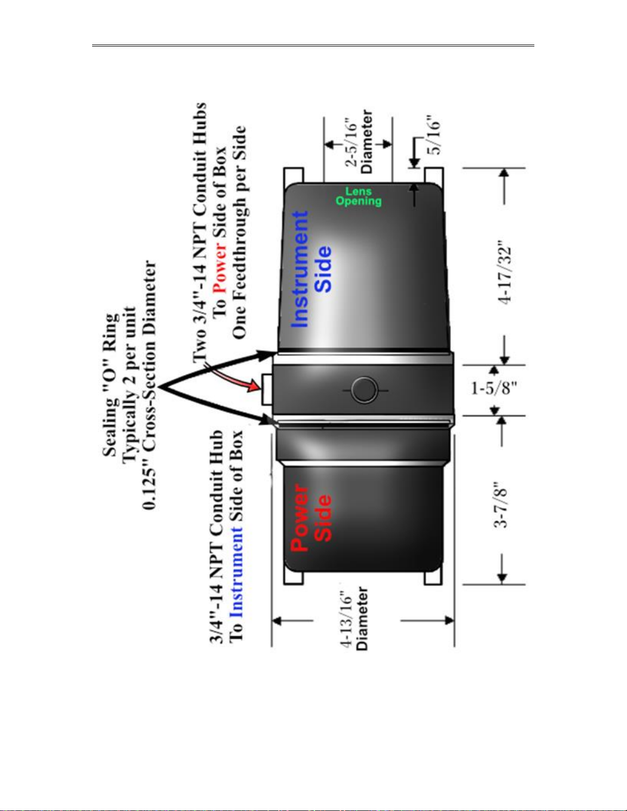
SFC332L Flow Computer: Dimensions
Date: 8/1/2019
Page 10

Dynamic Flow Computers SFC332L Manual Quick Start — 1-5
Starting and Installing theWindow Software:
System Minimum Requirements
In order to install this software product the following requirements must be met:
Windows Operating System (Win95, Win98, Win98SE, win2000, WinNT, WinXP, Vista,
Windows 7, Windows 8, Windows 10)
For Windows NT, 2000, XP or Vista: Administrator level access to create an ODBC system DNS.
Minimum disk space available: 16 MB.
1 Serial Communication Port
If your computer meets these requirements, you can run the setup file downloaded from our website
Date: 8/1/2019
Page 11
Dynamic Flow Computers SFC332L Manual Quick Start — 1-6
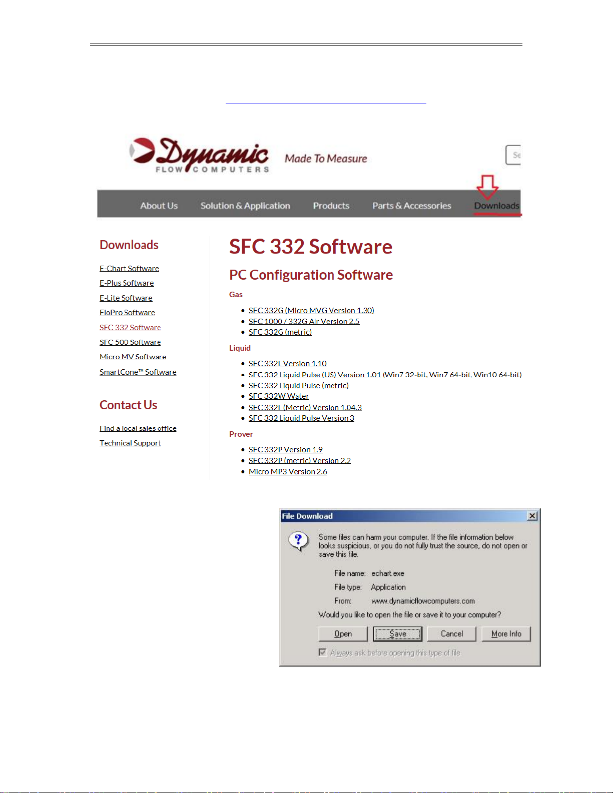
Website - DFC Configuration Software
Step 1. Go to our website WWW.DYNAMICFLOWCOMPUTERS.COM
Step 2. Click on the “Downloads”
Step 3. Select either Windows or
DOS software based on Step 2.
Step 4. On the new screen
presented to you click on the
application that you are trying to
download. Once you hit the link it
will ask you if you want to run or
save the file in your computer.
Select SAVE. (See illustration 1)
Date: 8/1/2019
Page 12
Dynamic Flow Computers SFC332L Manual Quick Start — 1-7
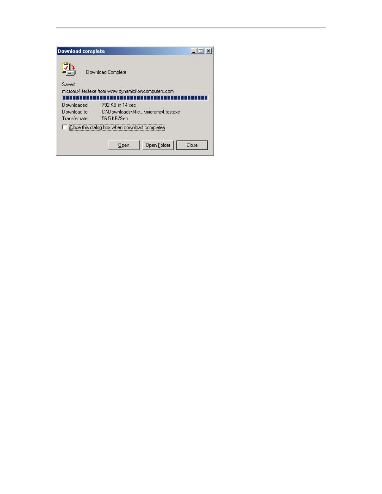
Step 5. The file will start to
transfer to your computer. The
download time depends on your
Internet connection speed and the
type of application that being
downloaded.
Step 6. When the download if
finish. Press the OPEN button to
start the setup process. (See
Illustration)
Step 7. Follow the steps in the
application setup.
Date: 8/1/2019
Page 13
Dynamic Flow Computers SFC332L Manual Quick Start — 1-8
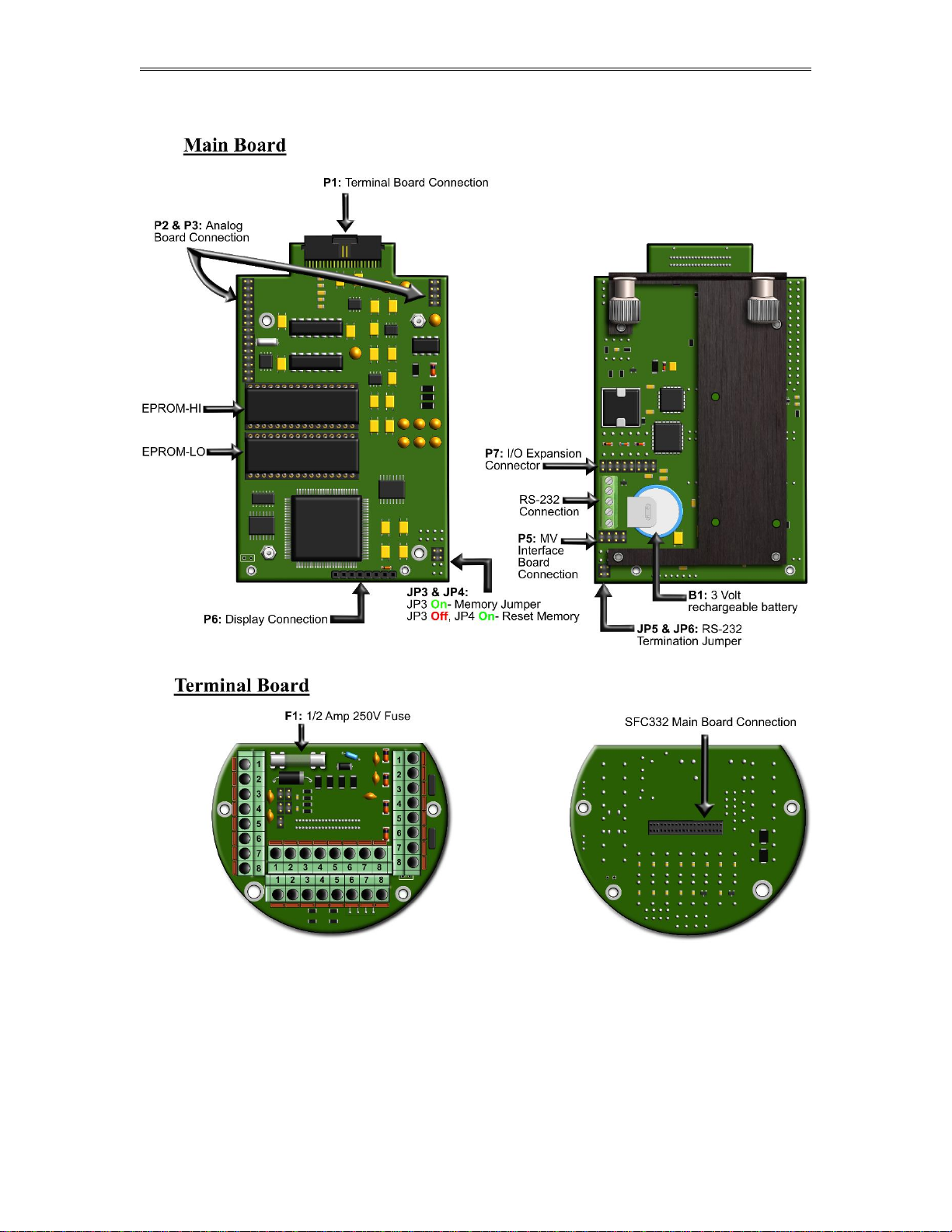
Getting acquainted with the flow computer wiring:
Back terminal wiring:
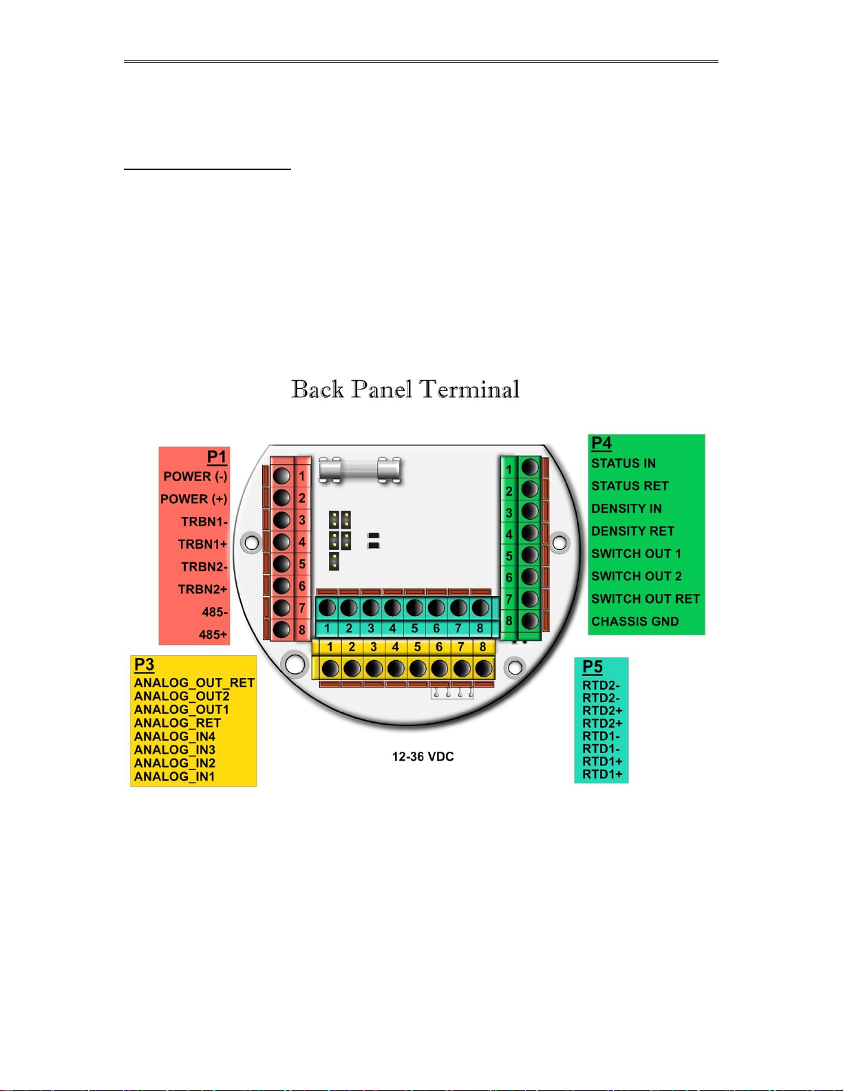
The back terminal wiring indicates the overall positions of the terminal plugs and their functions. Though
the back panel’s jumpers are also shown, refer to the next drawing, “Back Panel Jumpers”, for information
on their settings and functions.
The Smart Flow Computer receives its power via the two topmost pins on Terminal P1, on the left of the
terminal board. Also on Terminal P1 are, from top to bottom, inputs from the two turbines and the RS-485
serial connection.
To the right (P4), from top to bottom, are status input 1, density frequency input, and switch output 1 and 2.
Terminal P3, at the lower bottom, handles analog inputs and outputs. These are, in order from right to left,
analog inputs 1-4 and analog outputs 1 and 2.
Terminal P5, top middle, is the RTD terminal block, "100 platinum RTD input".
Date: 8/1/2019
Page 14
Dynamic Flow Computers SFC332L Manual Quick Start — 1-9
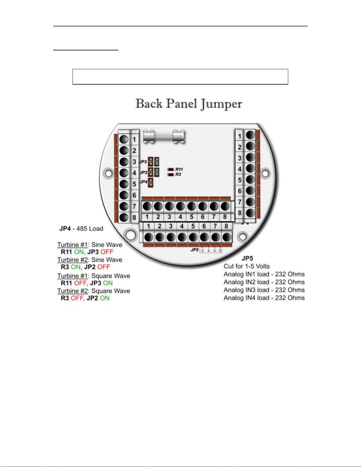
Back Panel Jumper
In this illustration, a jumper is “ON” when the jumper block is used to connect the jumper’s to wire prongs.
“OFF” means the jumper block is completely removed or attached to only one of the two wire prongs.
Note: R11 and R3 could have a vertical orientation instead of a horizontal
orientation on certain Smart Flow Computer models.
Date: 8/1/2019
Page 15
Dynamic Flow Computers SFC332L Manual Quick Start — 1-10
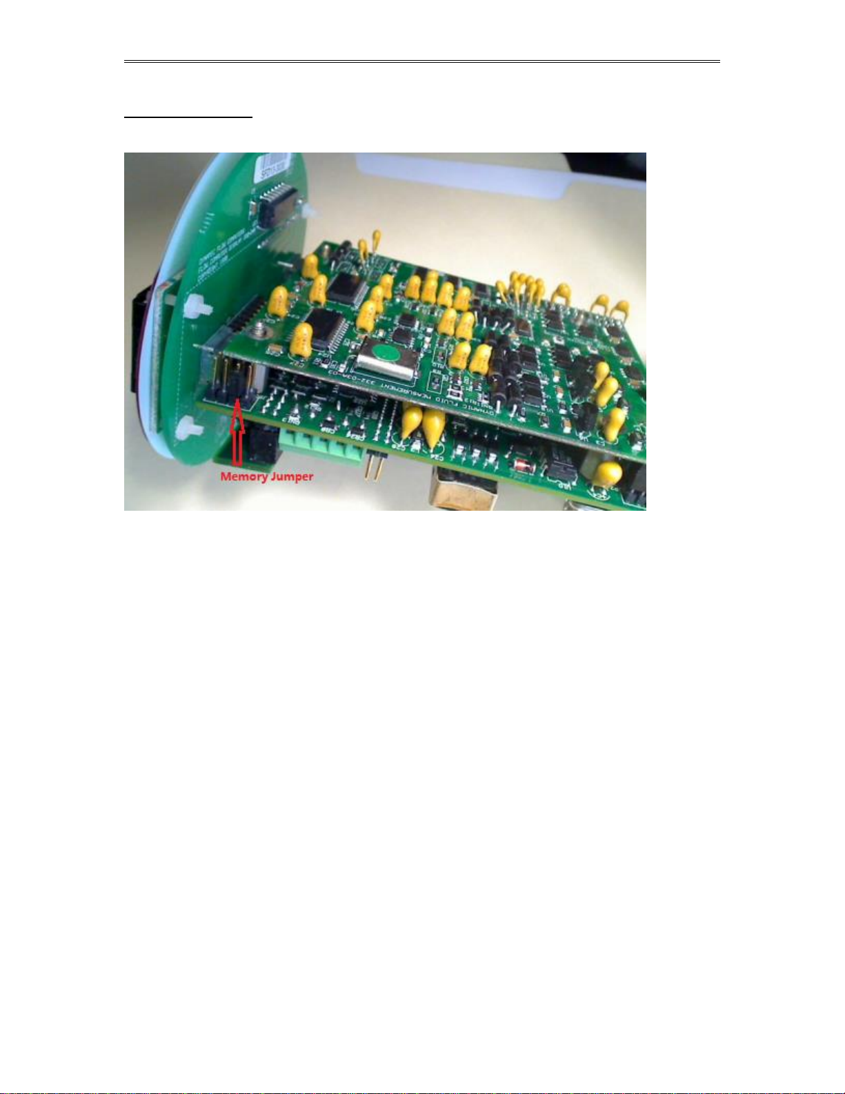
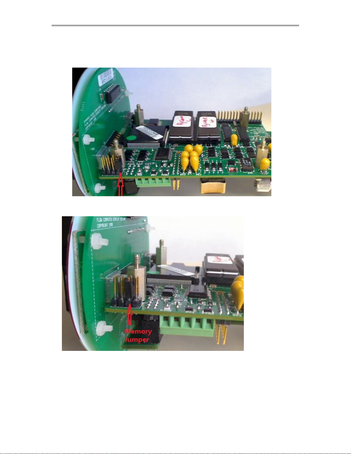
Memory Jumper
Date: 8/1/2019
Page 16
Dynamic Flow Computers SFC332L Manual Quick Start — 1-11
Steps to clear memory through removing the memory jumper
(1) Turn off the power, move the jumper to the next two pins, wait for 5 seconds
(2) Put the jumper back
Memory cleared and Flow Computer ID is set to 1, 9600 baud rate, RTU mode
Date: 8/1/2019
Page 17
Dynamic Flow Computers SFC332L Manual Quick Start — 1-12
Date: 8/1/2019
Page 18
Dynamic Flow Computers SFC332L Manual Quick Start — 1-13
Date: 8/1/2019
Page 19

Dynamic Flow Computers SFC332L Manual Quick Start — 1-14
INPUT/OUTPUT: Assigning and Ranging Inputs
Input/Output Assignment
We will now configure your SFC332L Flow Computer’s inputs and outputs. The flow computer allows the
user to configure the inputs and outputs. (I.e. Analog #1 is pressure for Meter #1). The flow computer will
not use the unassigned inputs.
How to assign a transmitter to an I/O point
1 Click “Configure Device”, configuration menu is prompted
2 On configuration menu, click “Input Assignment”
3 Enter assignments for DP, temperature, pressure, density and spare inputs.
4 Assignment (1-n). Assignments 1-4 are analog inputs attached
to terminal of the back panel. These inputs accept 4-20mA or 1-5
volts input and are suitable for temperature, pressure, density, or spare inputs. An assignment
5 is strictly RTD (temperature) input only for the meter, densitometer or spare. Assignment 7
indicates a density frequency input; it is assigned automatically once you choose live density
frequency input in the setup menu at density type Assignment 10 (module 1) is for
Rosemount multi-variable module only. DP, pressure, and temperature for the meter can be
assigned. When a frequency type primary element is hooked to the flow computer, the Multi
Variable pressure and temperature can be used and the DP becomes a spare input that could
be assigned for strainer differential.
Date: 8/1/2019
Page 20

Dynamic Flow Computers SFC332L Manual Quick Start — 1-15
Ranging the Transmitter Inputs:
1. Enter the range values: after assigning the inputs scroll down the transducer inputs
assignment menu to scale the 4-20mA. Enter the value at @4mA and @20mA. Enter both
values similar to the way the transmitter is ranged. 1-5 volts is equivalent to 4-20mA. Enter
the 1 volt value at the 4mA, and 5 volt value at 20mA. When the Multi Variable is used the 420 ma scale has no effect on anything and does not need to be configured for that input. The
reason is simply that the flow computer gets the data via digital communication from the
transmitter in engineering units, and therefore a scale is not needed. Normal pressure range is
0-3626, temperature –40 to 1200, DP –250 to 250, or -830 to 830 inches of water.
2. Enter the high and low limits: high limits and low limits are simply the alarm points in
which you would like the flow computer to flag as an alarm condition. Enter these values
with respect to the upper and lower range conditions. Try to avoid creating alarm log when
conditions are normal. For example: If the line condition for the pressure is between 0 to 500
PSIG, then you should program less than zero for low pressure alarm, and 500 or more for
high pressure alarm. High limits are also used in the SCALE for the Modbus variables. The
high limit is equalent to 32767 or 4095. The low limit is not used for calculating the scale.
The scale starts at zero to wherever the high limit value.
3. Set up the fail code: Maintenance and Failure Code values tell the flow computer
to use a default value in the event the transmitter fails. The default value is stored in
Maintenance. There are three outcomes: the transmitter value is always used, no matter
what (Failure Code = 0); the Maintenance value is always used, no matter what
(Failure Code = 1); and the Maintenance value is used only when the transmitter’s
value indicates that the transmitter has temporarily failed (Failure Code = 2).
RTD inputs will skip 4-20 mA assignment because RTD is a raw signal of 50 (ohms) to 156. Readings
beyond that range require a 4-20 mA signal to the flow computer or using the built in Rosemount Multi
Variable transmitter. The Rosemount Multivariable has a range of –40-1200 degrees Fahrenheit.
Density coefficients for raw frequency inputs are programmed in this menu. The menu will only show
parameters relevant to the live density selected (i.e., Solartron or UGC, etc.).
Date: 8/1/2019
Page 21

Dynamic Flow Computers SFC332L Manual Quick Start — 1-16
WIRING:
Wiring to the flow computer is very straightforward and simple. But still it is very important to get familiar
with the wiring diagram.
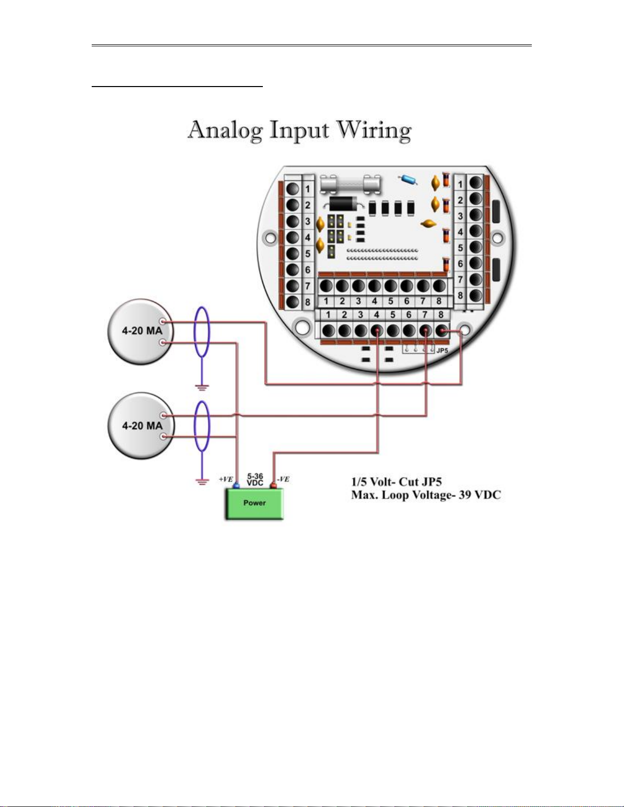
Wiring the Analog Inputs:
Typical wiring for analog inputs 1 and 2 are shown in the drawing. Analog inputs 3 and 4 are to the left of
analog 1 and 2. Note that the analog input has only one common return, which is the -Ve signal of power
supply powering the transmitters.
When wiring 1-5 volts, make sure to calibrate the flow computer for the 1-5 volt signal because the flow
computer calibration defaults for the 4-20mA, which is different from the 1-5 volts. JP5 must be cut for 15 volt inputs. The jumpers for analog 1-4 are in order from right to left. It is possible to cut the first two
jumpers for analog 1 & 2 in for 1-5 volts signal and have analog in 3 & 4 as 4-20mA signal. Signal line
impedance provided by our flow computer is less than 250. Therefore, when using a smart transmitter
that requires a minimum of 250 resistance in the loop, an additional resistor at the flow computer end
needs to be installed in series with the 4-20mA loop in order to allow the hand held communicator to talk to
the transmitter.
NOTE: The 4-20mA or 1-5 volt DOES NOT source power to the transmitters. You can use the DC
power feeding the flow computer to power the 4-20mA loop IF that power supply is
FILTERED.
Date: 8/1/2019
Page 22
Dynamic Flow Computers SFC332L Manual Quick Start — 1-17
Wiring the analog inputs 1-4 :
Date: 8/1/2019
Page 23
Dynamic Flow Computers SFC332L Manual Quick Start — 1-18
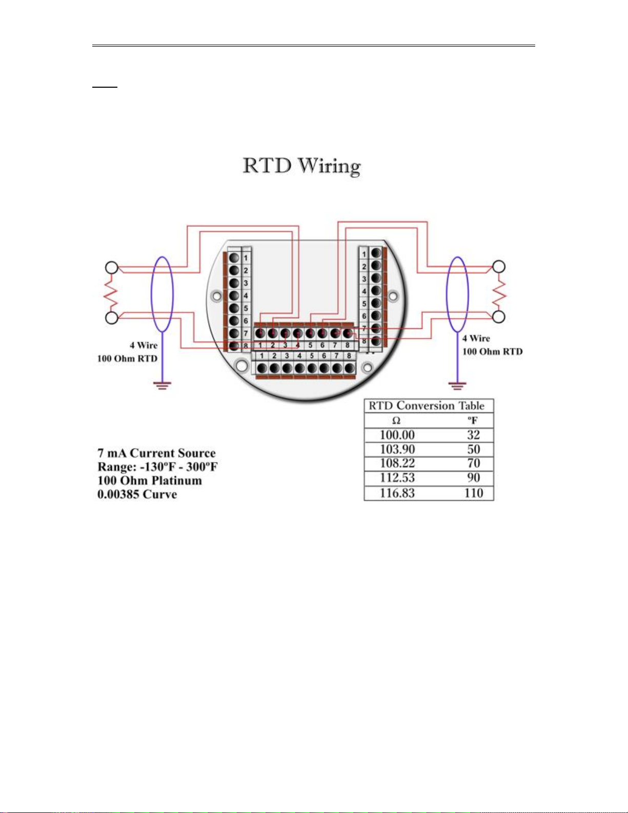
RTD
The flow computer shows wiring to RTD 1 and RTD 2. 100 platinum can be used; a temperature range
of -43F to +300F can be measured. RTD 1 is to the right where P5 designation is. In the figure below
notice that each side of the RTD requires two wire connections. When using less than 4 wires a jumper
must be used to make up for the missing lead. Internal excitation current source generated is approximately
7mA. .
RTD can be wired to multi-variable directly through specially provided cable. This wiring diagram
describes wiring directly into the flow computer and not into the multi-variable.
Date: 8/1/2019
Page 24
Dynamic Flow Computers SFC332L Manual Quick Start — 1-19
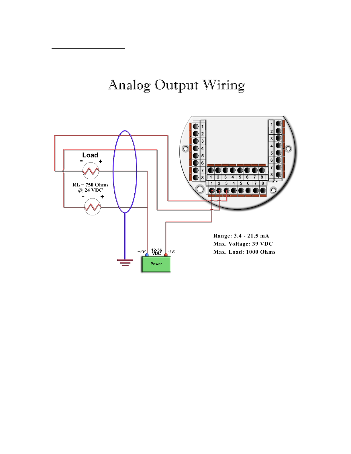
Wiring Analog Output:
Wiring diagram shows typical Analog output wiring. Notice that analog output will regulate 4-20 mA
current loop but DOES NOT source the power for it. External power is required.
ASSIGN ING/R ANGING THE 4-20MA AN ALOG OUT PUTS :
Go to the I/O assignment main menu and click Analog Output Assignment. A selection menu
is prompted. Select the analog output number, and then enter what the 4-mA output will indicate and the
20 mA. Make sure that the 20 mA assignment value exceeds the upper range limit of what you assigned
the Analog output for, otherwise the analog output will not update beyond 20 mA.
Date: 8/1/2019
Page 25

Dynamic Flow Computers SFC332L Manual Quick Start — 1-20
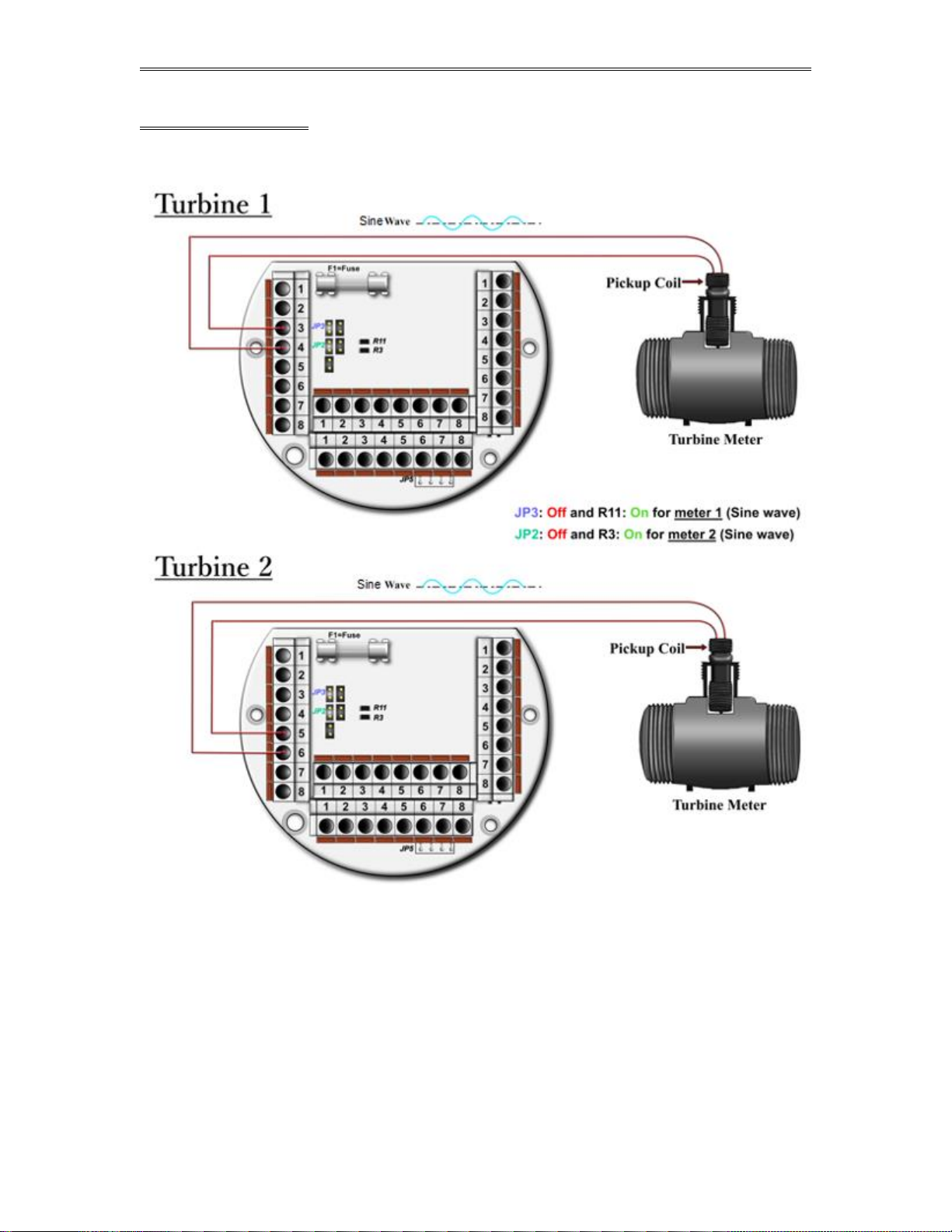
Turbine Input Wiring
Scroll to Turbine under Wiring and press ENTER. Two drawings above each other will show
typical wiring for turbine meter 1 and turbine meter 2. When dual pickups from the same turbine are
connected, use the inputs for turbine 1 for pickup 1 and turbine 2 for the second pickup coil. When
connecting sine wave directly from the pickup coil make sure the distance from the pickup coil to the flow
computer is very short--less than 50 feet with shielded cable. In the event there is presence of noise, the
distance must be shortened. When connecting sine wave signal, the R11 jumper for meter 1 must be
installed and R3 jumper for meter 2 must be installed. (JP3 and JP2 must be off when using sine wave).
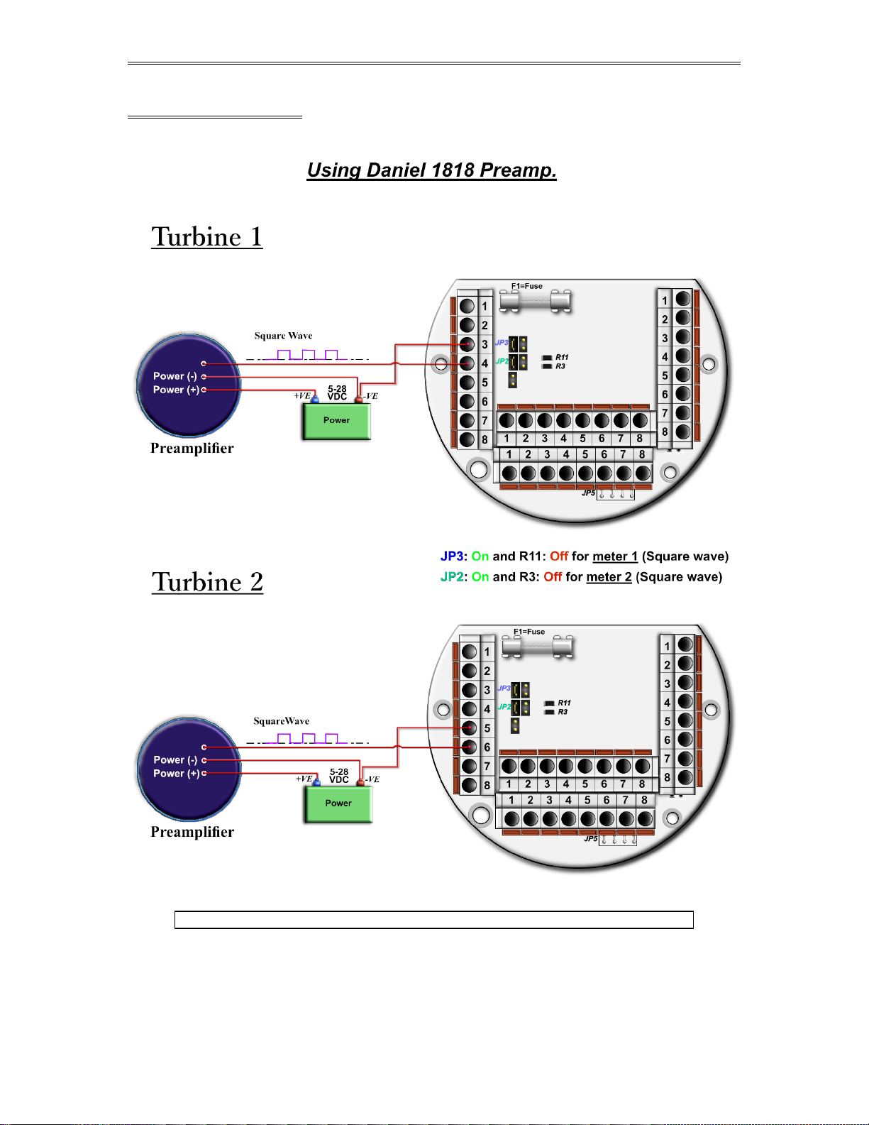
On the other hand, when using square wave, the square wave signal can be sinusoidal but has to be above 5
volts peak to peak with less than 0.4 volts offset in order for the flow computer to read it. R11 and R3 must
be off and JP3 on for meter 1; JP2 must be on for meter 2.
Note: When connecting square wave input, the JP3 and JP2 connect the turbine return to the
flow computer power return. Therefore, signal polarity is very important. Reverse polarity
could result in some damage or power loss. When sine wave is used the signal polarity is
usually of no significance.
The turbine input is immediately under the power input on terminal P1. The third pin down from the top is
Turbine/PD "minus", and below it is Turbine plus. The second pulse input for Turbine/PD meter 2 or the
second pickup coil is below turbine one input on P1. The fifth pin down from the top is turbine 2 "minus"
signal and below it is Turbine/PD 2 plus signal.
Date: 8/1/2019
Page 26
Dynamic Flow Computers SFC332L Manual Quick Start — 1-21
TUR BINE- SINE WAVE
Date: 8/1/2019
Page 27
Dynamic Flow Computers SFC332L Manual Quick Start — 1-22
TUR BINE-SQUARE WAVE
Note: R11 and R3 are oriented vertically in some flow computers.
Date: 8/1/2019
Page 28
Dynamic Flow Computers SFC332L Manual Quick Start — 1-23
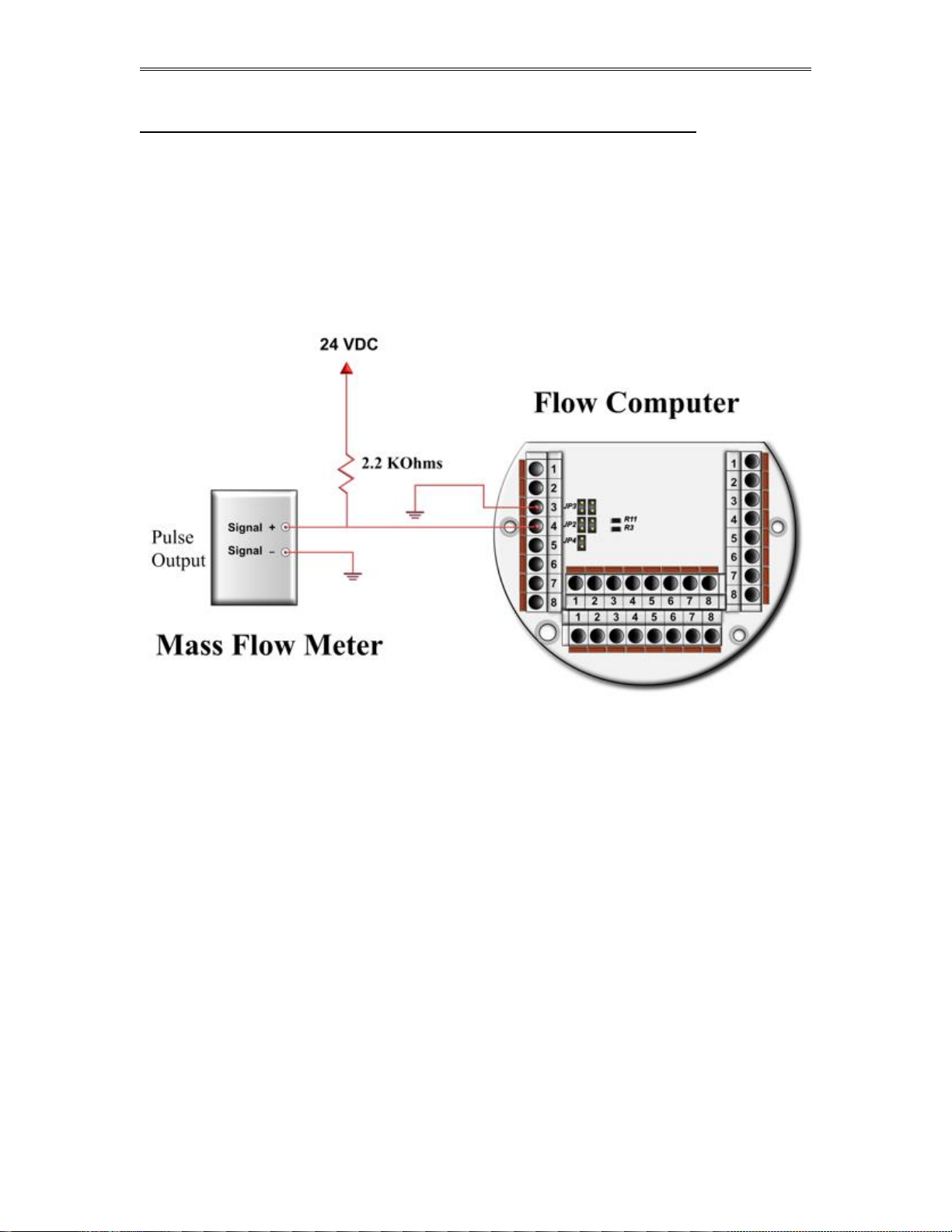
Turbine input wiring for passive (dry contact) pulse generators
Some mass flow meters have pulse outputs that do not provide power but instead require
external power, they are referred to as passive outputs, dry outputs, open collector, etc. (For
example the Krohne UFM 3030 Mass meter).
In these cases the wiring should be as shown on the below diagram. The pull up resistor can be
adjusted to limit the current sink by the Mass meter. For Turbine Input 1 JP3 must be ON and
R11 OFF and if using Turbine Input 2 then JP2 must be ON and R3 OFF.
Date: 8/1/2019
Page 29
Dynamic Flow Computers SFC332L Manual Quick Start — 1-24
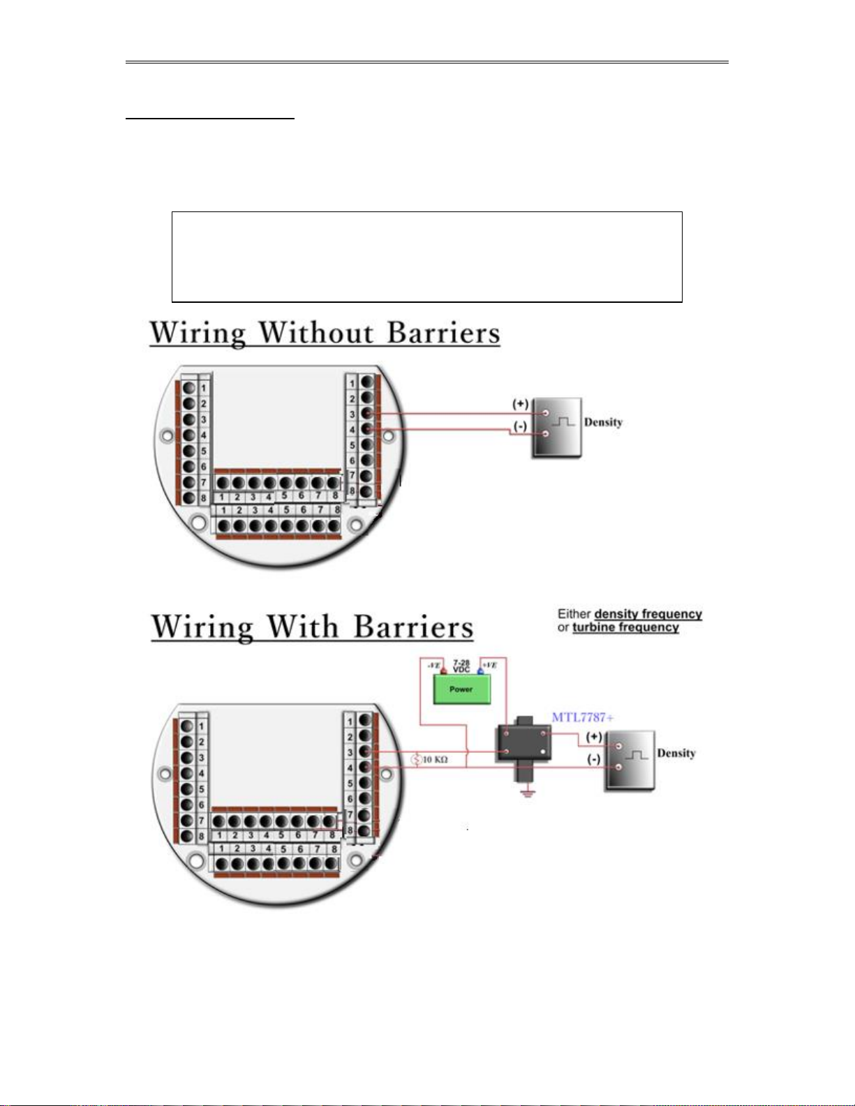
Density Input Wiring:
When using a live densitometer input with frequency signal, the signal can be brought into the Smart Flow
Computer in its raw form. The Smart Flow Computer accepts a sine wave or square with or without DC
offset. Example for density wiring can be seen in the wiring diagram. Three are two drawings, one with
barrier and the other without. Barriers are used for area classification. Notice that the RTD wiring is also
drawn to show how to hook the density RTD signal.
Note: When wiring the density input polarity is of significance and reverse polarity could
result in some damage or power loss. The density signal is on connector P4, the
third and fourth pin down from the top. The third pin down is density plus, the
fourth down is density minus. When Density input is 4-20mA it should be
connected as a regular 4-20mA signal to the analog input and not the density
frequency input.
Date: 8/1/2019
Page 30
Dynamic Flow Computers SFC332L Manual Quick Start — 1-25
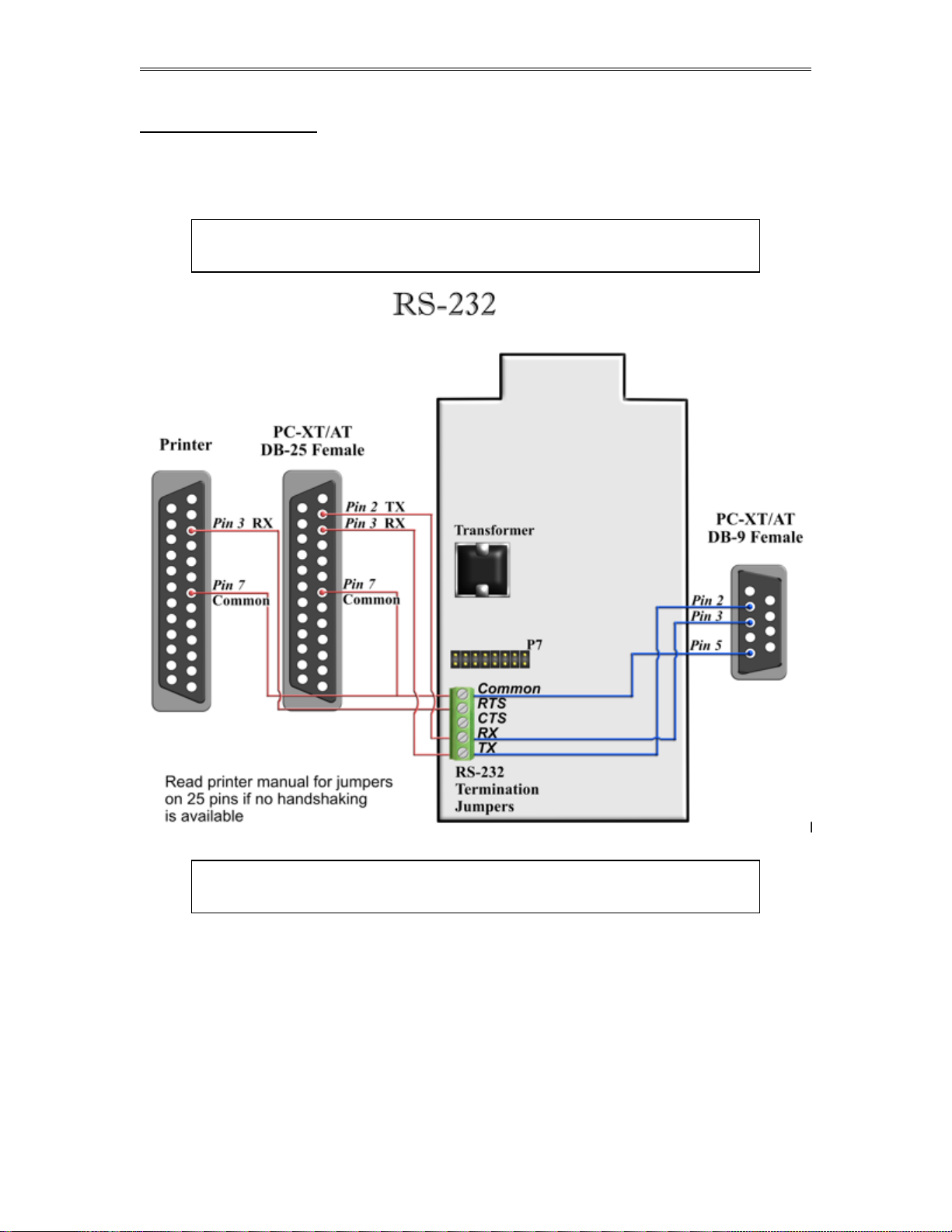
RS-232 Connection:
The RS-232 is not located on the terminal board. The RS-232 is a green 5-pin terminal block with screw
type connector located on the display side of the enclosure. Go to Wiring | RS-232. Termination
jumpers for the RS-232 are located at the top corner of the board on the same side of the RS-232 connector.
The two jumpers at the top are for terminating the transmit line and below it is the receive line.
The RS-232 port can be used for printing reports, Modbus communication, or interfacing
to the configuration program. If the port is configured as printer port in the flow
computer Note: Twisted shielded cable is required.
WARNING: When the RS-232 terminal is used with a modem, external protection on the
phone line is required. Jumper DTR to DSR, RTS to CTS, and disable software
handshake on the modem RS232 connection
Date: 8/1/2019
Page 31

Dynamic Flow Computers SFC332L Manual Quick Start — 1-26
RS-485:
RS-485 wiring is shown in the wiring diagram under RS-485. The RS-485 termination jumper is JP4
located on the back terminal. The maximum distance when 18-gauge wire is used would be 4000 feet.
Note: Twisted shielded cable is required.
WARNING: When the RS-485 terminal is used, external transient protection and optical
isolation is required, especially for long distance wiring.
Date: 8/1/2019
Page 32

Dynamic Flow Computers SFC332L Manual Quick Start — 1-27
Wiring of Status Inputs:
There is one status input standard and an optional three more on the back of the CPU board. The standard
status input is shown in the wiring diagram under Status Input. It has 4 volts of noise hysteresis,
with a trigger point of 5 volts and an off point of 1 Volt. Status inputs 2, 3, and 4 require the I/O expansion
connector and its wires be installed; refer to wiring drawing IO-Exp. Connection numbers 6, 7, and 8 are
the status in (positive) for inputs 2, 3, and 4, respectively, and 11 is the return for all three inputs.
Date: 8/1/2019
Page 33

Dynamic Flow Computers SFC332L Manual Quick Start — 1-28
Wiring of Switch/Pulse Outputs:
Go to Switch output under Wiring. The wiring diagram shows switch 1 and 2 and the return.
Please note that switches 3, 4, and 5 cannot be used for pulse output; switches 1 and 2 can be used for pulse
or switch output. See also I/O Expansion. Notice that the switch outputs are transistor type outputs (open
collector type with maximum DC rating of 350 mA continuous at 24 VDC) and require external power.
Date: 8/1/2019
Page 34

Dynamic Flow Computers SFC332L Manual Quick Start — 1-29
Connection
Purpose
Comments
1
Detector switch 1
Requires prover option CPU to operate.
Rating: 5-36 Vdc
2
Detector switch 2
3
Switch output 3
Maximum rating: 75mA @24 volts
Range: 5-36 Vdc
4
Switch output 4
5
Switch output 5
6
Status input 2
Rating: 6-36 Vdc
7
Status input 3
8
Status input 4
9
Return: detector switches
10
Return: switches 3, 4, 5
11
Return: status 2, 3, and 4
I/O Expansion:
The I/O expansion is 16-pin connector next to the RS-232 terminal. Eleven pins of the 16-pin connector
are utilized. When the flow computer is ordered with the I/O expansion feature, the wires and the plug are
provided with the flow computer. There will be 11 wires with the wire number tag at the outer end of the
wire. The tag will indicate the wire number. The following is the sequence for the wires. On the top right
edge of the connector towards the top outer side of the CPU board is pin 1, across from it is pin 9.
Date: 8/1/2019
Page 35

Dynamic Flow Computers SFC332L Manual Quick Start — 1-30
Date: 8/1/2019
Page 36

Dynamic Flow Computers SFC332L Manual Quick Start — 1-31
Connection
No.
Purpose
Comments
1
Detector switch 1
Requires prover option CPU to operate.
Rating: 5-36 Vdc
2
Detector switch 2
3
Switch output 3
Maximum rating: 75mA @24 volts
Range: 5-36 Vdc
4
Switch output 4
5
Switch output 5
6
Status input 2
Rating: 6-36 Vdc
7
Status input 3
8
Status input 4
9
Return: detector switches
10
Return: switches 3, 4, 5
11
Return: status 2, 3, and 4
12
RS232 TX
13
RS232 RX
14
RS232 RTS
15
RS232 ret
Prover/Expansion
Date: 8/1/2019
Page 37

Dynamic Flow Computers SFC332L Manual Quick Start — 1-32
CALIBRATION Through Window Program
Calibrations are performed under Calibration. Select inputs to be calibrated, and then select full,
single, offset calibration method.
Analog Input 4-20mA or 1-5 volt signal
OFF SET CALIBRATION:
For simple offset type calibration simply induce the signal into the analog input and make sure the
SFC332L is reading it. After you verify that the SFC332 recognized the analog input, enter the correct mA
reading, and then click OK. The offset type calibration is mainly used when a small offset adjustment
needs to be changed in the full-scale reading. The offset will apply to the zero and span. Offset is the
recommended method for calibrating the temperature input.
FULL CALIBRATION METHOD:
To perform full calibration be prepared to induce zero and span type signal.
1. Induce the low end signal i.e. 4mA in the analog input.
2. Click inputs to be calibrated under calibration menu, click full calibration, enter the first point
- the analog input value i.e. 4mA, and then click OK button.
3. Now be ready to enter the full-scale value. Simply induce the analog signal and then enter
the second value i.e. 20mA, and then click OK button
4. Induce live values to verify the calibration.
TO USE DEFAULT CALIBRATION
1. Select Analog Input
2. Select Reset calibration method
3. Now verify the live reading against the flow computer reading
Date: 8/1/2019
Page 38

Dynamic Flow Computers SFC332L Manual Quick Start — 1-33
RTD Calibration:
RTD Calibration is a 2-step process. The first step is a onetime procedure to verify transducer
linearity and is done at the time the meter is being setup. The second step is the routine calibration
sequence.
Step 1 – Linearity Verification
1- Use a Decade box with 0-150 °F settings.
2- Connect RTD cable to this resistive element for verification of linearity. Verify low and high
points. It must be within ½ degree.
3- Connect the actual RTD element and compare with a certified thermometer.
4- If not within ½ degree do a Full Calibration (See Full Calibration below). If problem persists
verify other elements such as RTD Probe, connections, shield, conductivity of connectors,
etc.
The purpose of the above procedure is to verify zero and span and make sure that the two points
fall within the expected tolerance.
Step 2 – Routine Calibration
Once Linearity has been verified through Step 1, the routine calibration procedure is reduced to
simply connecting the actual RTD and doing an offset point calibration (see offset calibration
below).
Calibration after that will be simple verification for the stability of the transmitter. If it drifts abnormally
then you need to verify the other parts involved.
Calibration Procedures through Windows™ Software
At the top menu, go to Calibration and Select RTD Input.
RESET TO DEFAULT CALIBRATION
1. Select Reset calibration method
2. Now verify the live reading against the flow computer reading
OFFSET CALIBRATION:
1. Select offset calibration method.
2. Induce a live value and wait for 10 seconds for the reading to stabilize. Then enter the live
value. The value entered must be in Ohm only.
3. Now verify the live reading against the flow computer reading
FULL SCALE CALIBRATION:
1. Prepare low range resistive input (i.e., 80 Ohm.) and High range resistive input (i.e., 120. Ohm).
2. Go to the calibration menu and select RTD full calibration method. Induce the low end (80
Ohm.) resistive signal and then wait 10 seconds, enter live value in ohm value, and click OK
button.
3. Induce the High range signal (120 Ohm.) and wait 10 seconds, then enter live value in Ohm
and click OK button.
4. Now verify the live reading against the flow computer reading.
Date: 8/1/2019
Page 39

Dynamic Flow Computers SFC332L Manual Quick Start — 1-34
Calibration of Analog Output:
Follow the following steps to calibrate the analog output against the end device
1. Go to the calibration menu, select analog output, and then select method. Full calibration will
cause the flow computer to output the minimum possible signal 4 mA. Enter the live output
value reading in the end device i.e. 4 mA and click OK button. Now the flow computer will
output full scale 20 mA. Enter the live output i.e. 20 then click OK button.
2. Now verify the output against the calibration device.
Multi-Variable Transmitters (Model 205) – DP and Pressure
Calibrations are performed under Calibration. . Select inputs to be calibrated, and then select full,
single, offset calibration method.
OFF SET CALIBRATION
1. Induce live value for pressure or DP.
2. Select Multivariable DP or pressure.
3. Select offset calibration method, enter offset, and click OK button.
4. Now read induce live values to verify the calibration.
FULL SCALE CALIBRATION
1. Induce live value for pressure or DP.
2. Select Multivariable DP or pressure
3. Select full calibration method
4. Induce the low range signal, enter the first point, and then click OK button.
5. Induce the high range signal, enter the second point, and then click OK button.
6. Now verify the live reading against the flow computer reading.
TO USE DEFAULT CALIBRATION
1. Select Multivariable DP or pressure
2. Select Reset calibration method
3. Now verify the live reading against the flow computer reading
While doing calibration before downloading any of the calibrated values, it is a good practice to verify that
the SFC332L close reading to the induced value.
The DP reading must be re-calibrated for the zero offset after applying line pressure.
Date: 8/1/2019
Page 40

Dynamic Flow Computers SFC332L Manual Quick Start — 1-35
Multi-Variable Transmitters (Model 205) –RTD
RTD Calibration is a 2-step process. The first step is a onetime procedure to verify transducer
linearity and is done at the time the meter is being setup. The second step is the routine calibration
sequence.
Step 1 – Linearity Verification
1. Use a Decade box with 0-150 °F settings.
2. Connect RTD cable to this resistive element for verification of linearity. Verify low and high
points. It must be within ½ degree.
3. Connect the actual RTD element and compare with a certified thermometer.
4. If not within ½ degree do a Full Calibration (See Full Calibration below). If problem persists
verify other elements such as RTD Probe, connections, shield, conductivity of connectors, etc.
The purpose of the above procedure is to verify zero and span and make sure that the two points
fall within the expected tolerance.
Step 2 – Routine Calibration
Once Linearity has been verified through Step 1, the routine calibration procedure is reduced to
simply connecting the actual RTD and doing an offset point calibration (see offset calibration
below).
Calibration after that will be simple verification for the stability of the transmitter. If it drifts abnormally
then you need to verify the other parts involved.
Calibration Procedures through Windows™ Software
At the top menu, go to Calibration and Select RTD Input.
RESET TO DEFAULT CALIBRATION
1. Select Reset calibration method
2. Now verify the live reading against the flow computer reading
OFFSET CALIBRATION:
1. Select offset calibration method.
2. Induce a live value and wait for 10 seconds for the reading to stabilize. Then enter the live
value. The value entered must be in Degrees only.
3. Now verify the live reading against the flow computer reading
FULL SCALE CALIBRATION:
1. Prepare low range resistive input (i.e., 80 Ohm.) and High range resistive input (i.e., 120.
Ohm).
2. Go to the calibration menu and select RTD full calibration method. Induce the low end (80
Ohm.) resistive signal and then wait 10 seconds, enter the equivalent temperature in degrees,
and click OK button.
3. Induce the High range signal (120 Ohm.) and wait 10 seconds, then enter the temperature
degrees equivalent to 120 Ohm and click OK button.
4. Now verify the live reading against the flow computer reading.
Date: 8/1/2019
Page 41

Dynamic Flow Computers SFC332L Manual Quick Start — 1-36
CALIBRATION Through DOS Program
Analog Input 4-20mA or 1-5 volt signal:
Calibrations are performed under I/O | Calibration. Use the arrow keys to scroll to
Calibration and press <ENTER>. After you press <ENTER> the screen should show
COMMUNICATION STATUS:OK.
OFF SET CALIBRATION:
For simple offset type calibration simply induce the signal into the analog input and make sure the flow
computer is reading it. After you verify that the flow computer recognized the analog input press <F8>.
The screen will freeze. Scroll down to the analog input you are calibrating and enter the correct mA
reading. Then press <ENTER> followed by <F3> to download. The screen will stay in the freeze mode. To
bring the live readings press <F2> and then the flow computer will display the new calibrated readings.
The offset type calibration is mainly used when a small offset adjustment needs to be changed in the fullscale reading. The offset will apply to the zero and span.
FULL CALIBRATION METHOD:
To perform full calibration be prepared to induce zero and span type signal.
1. Induce the low end signal i.e. 4mA in the analog input.
2. Press <F8> and scroll down to the reading then press <ALT><R>(alternate key and the letter
R simultaneously). Then immediately enter the analog input value i.e. 4mA. Follow that by
<ENTER> and pressing the <F3> function key to download data.
3. Now be ready to enter the full-scale value. Simply induce the analog signal and then enter
the value i.e. 20mA, and then download by pressing <ENTER> then <F3> function key.
4. Induce live values to verify the calibration.
DEF AULT CALIBRATION
Simply press <F8> and scroll to the analog Input and press <ALT><R> followed by <F3 function key.
Date: 8/1/2019
Page 42

Dynamic Flow Computers SFC332L Manual Quick Start — 1-37
RTD calibration:
For offset calibration simply go to I/O | Calibration and press <ENTER>. Once the flow computer
shows communication status OK press <F8> and scroll to RTD 1 or RTD 2. RTD Calibration is a 2-
step process. The first step is a onetime procedure to verify transducer linearity and is done at the
time the meter is being setup. The second step is the routine calibration sequence.
Step 1 – Linearity Verification
1. Use a Decade box with 0-150 °F settings.
2. Connect RTD cable to this resistive element for verification of linearity. Verify low and high points.
It must be within ½ degree.
3. Connect the actual RTD element and compare with a certified thermometer.
4. If not within ½ degree do a Full Calibration (See Full Calibration below). If problem persists verify
other elements such as RTD Probe, connections, shield, conductivity of connectors, etc.
The purpose of the above procedure is to verify zero and span and make sure that the two points
fall within the expected tolerance.
Step 2 – Routine Calibration
Once Linearity has been verified through Step 1, the routine calibration procedure is reduced to
simply connecting the actual RTD and doing an offset point calibration (see offset calibration
below).
Calibration after that will be simple verification for the stability of the transmitter. If it drifts abnormally
then you need to verify the other parts involved.
RESET TO DEFAULT CALIBRATION
To go back to the default calibration simply press <F8> and scroll to the RTD input, and press
<ALT> <R> key followed by <F3> function key.
OFFSET CALIBRATION:
For offset calibration simply go to I/O | Calibration and press < ENTER>. Once the flow
computer shows communication status OK press <F8> function key and scroll to RTD. Induce a
live value and wait for 10 seconds for the reading to stabilize. Then enter the live value followed
by <F3> function key to download the direct reading. The value entered must be in ohms only.
FULL SCALE CALIBRATION:
1. Prepare low range resistive input (i.e., 80) and High range resistive input (i.e., 120). Go to
the calibration menu and press <F8> function key. Scroll to the RTD input you are calibrating
and press <ALT> <R> (key <ALT> and the letter R at the same time). Induce the low end
(80) resistive signal and then wait 10 seconds and enter 80 followed by pressing the <F3>
function key.
2. Induce higher range signal (120) and wait 10 seconds, then enter the number 120 ohm and
press the <F3> key.
3. Now verify the live reading against the flow computer reading.
Date: 8/1/2019
Page 43

Dynamic Flow Computers SFC332L Manual Quick Start — 1-38
Calibration of Analog Output:
To calibrate the analog output against the end device follow the following steps:
1. Go to the calibration menu and press <F8>. Scroll down to analog output and press <ENTER >
and then <ALT><R>. This will cause the flow computer to output the minimum possible
signal 3.25 mA. Enter the live output value reading in the end device i.e. 3.25 mA and press
<F3> function key. Now the flow computer will output full scale 21.75 mA. Enter the live
output i.e. 21.75 then press the <F3> function key.
2. Now verify the output against the calibration device.
Multi-Variable Transmitters (Model 205)- DP and Pressure
OFF SET CALIBRATION
1. Induce live value for temperature, pressure, or DP.
2. Go to Calibration - Multi-Variable menu.
3. Press <F8>, point to the value being calibrated, enter the correct value followed by
<ENTER> key, and then press <F3> function key to download data.
4. Now read induce live values to verify the calibration.
FULL SCALE CALIBRATION
1. Press <F8>. Scroll to the parameter to be calibrated, and then press <ALT><R>.
2. Induce the low range signal, then press <ENTER> followed by <F3> function key.
3. Induce the low range signal, then press <ENTER> followed by <F3> function key.
4. Now verify the live reading against the flow computer reading.
TO USE DEFAULT CALIBRATION
1. Select Multivariable DP or pressure
2. Select Reset calibration method
3. Now verify the live reading against the flow computer reading
Date: 8/1/2019
Page 44

Dynamic Flow Computers SFC332L Manual Quick Start — 1-39
Multi-Variable Transmitters (Model 205)- RTD
Calibrations are performed under I/O | Calibration. Use the arrow keys to scroll to
Calibration-Multi-Variable and press < ENTER>. After you press < ENTER> the screen
should show COMMUNICATION STATUS : OK.
RTD Calibration is a 2-step process. The first step is a onetime procedure to verify transducer
linearity and is done at the time the meter is being setup. The second step is the routine calibration
sequence.
Step 1 – Linearity Verification
1. Use a Decade box with 0-150 °F settings.
2. Connect RTD cable to this resistive element for verification of linearity. Verify low and high points.
It must be within ½ degree.
3. Connect the actual RTD element and compare with a certified thermometer.
4. If not within ½ degree do a Full Calibration (See Full Calibration below). If problem persists verify
other elements such as RTD Probe, connections, shield, conductivity of connectors, etc.
The purpose of the above procedure is to verify zero and span and make sure that the two points
fall within the expected tolerance.
Step 2 – Routine Calibration
Once Linearity has been verified through Step 1, the routine calibration procedure is reduced to
simply connecting the actual RTD and doing an offset point calibration (see offset calibration
below).
Calibration after that will be simple verification for the stability of the transmitter. If it drifts abnormally
then you need to verify the other parts involved.
RESET TO DEFAULT CALIBRATION
To go back to the default calibration simply press <F8> and scroll to the RTD input, and press
<ALT> <R> key followed by <F3> function key.
OFFSET CALIBRATION:
For offset calibration simply go to I/O | Calibration and press < ENTER>. Once the flow
computer shows communication status OK press <F8> function key and scroll to RTD. Induce a
live value and wait for 10 seconds for the reading to stabilize. Then enter the live value followed
by <F3> function key to download the direct reading. The value entered must be in degrees only.
FULL SCALE CALIBRATION:
1. Prepare low range resistive input (i.e., 80) and High range resistive input (i.e., 120). Go to
the calibration menu and press <F8> function key. Scroll to the RTD input you are calibrating
and press <ALT> <R> (key <ALT> and the letter R at the same time). Induce the low end
(80) resistive signal and then wait 10 seconds and enter the equivalent temperature in
degrees followed by pressing the <F3> function key.
2. Induce Higher range signal (120) and wait 10 seconds, then enter the temperature degrees
equivalent to 120 followed by pressing the <F3> function key.
3. Now verify the live reading against the flow computer reading.
Date: 8/1/2019
Page 45

Dynamic Flow Computers SFC332L Manual Quick Start — 1-40
Verifying Digital Inputs and Outputs
Use the diagnostic menu. A live input and output is displayed On the top of the screen pulse inputs and
density frequency input are shown. Compare the live value against the displayed value on the screen.
Failure to read turbine input could be a result of the preamp being bad or the jumper selection for sine and
square wave input are not in the right position. Refer to wiring diagram Wiring | Turbine for
proper turbine input wiring. Density input can be sine or square wave with or without DC offset.
Minimum accepted signal has to be greater than 1.2 volt peak to peak. Status input is shown below the
frequency input to the left of the screen. When the status input is on, the live diagnostic data will show ON.
Minimum voltage to activate the status is 7 volts with negative threshold of 2 volts. Switch outputs are to
the right of the status inputs. The switch outputs are open collector and require external voltage.
Date: 8/1/2019
Page 46

Dynamic Flow Computers SFC332L Manual Data Entry — 2-1
CHAPTER 2: Data Entry
and Configuration Menus
Introduction to the SFC332L Computer Software
The SFC332L software is constructed around a menu-driven organization
Configuration File through Window Program
New
Create a new file to store all the programmed information for one SFC332L Flow Computer. After a file is
opened it becomes the currently active file, its contents can be viewed and its parameters can be edited.
Open
Use this function to open an existing configuration file. After a file is opened it becomes the currently
active file, its contents can be viewed and its parameters can be edited. When this function is chosen a list
of existing configuration files is displayed. Select the file to be opened.
Close
Close or exit configuration file.
Save
When permanent modifications are performed on a file, user must save the new changes before exiting the
program, or proceeding to open a different file.
Save As
Use Save As to save the parameters in the currently active file (that is, the parameter values currently being
edited) to a new file. The original file will remain in memory.
Date: 8/1/2019
Page 47

Dynamic Flow Computers SFC332L Manual Data Entry — 2-2
VIEW
View Drawings
Select the wiring diagram to be displayed. (See details in chapter 1)
Back Panel
Analog Input
RTD
Analog Output
Status Input
Switch Output
Turbine
Densitometer
RS 232
RS 485
Jumpers
I/O Expansion
Prover/Expansion
Dimensions
Date: 8/1/2019
Page 48

Dynamic Flow Computers SFC332L Manual Data Entry — 2-3
TOOLS
Com Settings
PORT - COMMUNICATION PORT NUMBER (1,2,3,4)
Enter the PC port used to communicate with the SFC332L Flow Computer.
Baud Rate
Note: this parameter must be set the same for both the PC and the SFC332L Flow
Computer for communication to occur.
Baud rate is defined as number of bits per second. The available selections are 1200, 2400, 4800, 9600, or
19200.
Parity
Note: this parameter must be set the same for both the PC and the SFC332L Flow
Computer for communication to occur.
RTU - NONE
ASCII - EVEN or ODD
Set the parity to match the Modbus Type.
Data Bits
Options available: 5, 6, 7, or 8. Generally used: 8 for RTU mod, 7 for ASCII mode.
Stop Bits
Options available: 1, 1.5,or28. Generally used: 1.
Modbus Type
Note: this parameter must be set the same for both the PC and the SFC332L Flow
Computer for communication to occur.
The Modbus Communication Specification is either Binary RTU or ASCII.
Unit ID Number
The Unit ID Number is used strictly for communication purposes; it can take any value from 1 to 247. Only
one master can exist in each loop.
Note: Do not duplicate the Unit ID number in a single communication loop!
This situation will lead to response collisions and inhibit communications
to units with duplicate ID numbers.
Time Out
The amount of time in seconds the program will wait for an answer from the flow computer.
Retry Times
Retry times for the program to communicate with the flow computer in case of timeout.
Auto Detect Settings
Click this button and the configuration program will attempt to communicate with a single SFC332L Flow
Computer at different baud rates and formats.
Failure to communicate can occur because of a wiring problem, wrong PC port selection, communication
parameter mismatch between PC and SFC332L Flow Computer (Modbus type, parity, baud rate, etc.) or
lack of power to the SFC332L Flow Computer. To use this feature, the user must insure that only one
SFC332L Flow Computer is connected to the PC. More than one SFC332L Flow Computer in the loop
will cause data collisions and unintelligible responses
Date: 8/1/2019
Page 49

Dynamic Flow Computers SFC332L Manual Data Entry — 2-4
Meter Configuration
METER SETTINGS
Company Name
Up to 20 characters. The company name appears in the reports.
Meter Location
Up to 20 characters. This entry appears only in the report and serves no other function.
Day Start Hour (0-23)
Day start hour is used for batch operation. If daily batch is selected, the batch will end at day start hour; all
batch totalizers and flow-weighted values are reset.
Disable Alarms
Use Disable Alarms to ignore alarms. When the alarm function is disabled alarms are not logged. Alarms
are also not logged if the DP is below the cut-off limit.
Common Parameters
This feature allows the Flow Computer to use the transmitters on meter one to substitute and compensate
for meter two.
Atmospheric Pressure
This pressure is local pressure or contracted atmospheric pressure. (I.e. 14.73 PSI).
Select Scale Value
Scale value use high limit parameters. Full-scale value can be selected using 32767 with sign bit or as
4095 analog values.
Example:
Temperature high limit is set as 150 Degree F. and current temperature reading is 80 Degree F
Scale value will read 17475 = 80/150x32767 (if 0 is selected), or 2184=80/150 x 4095 (if 1 is selected)
Meter Bank
Single or two meters run configuration per individual SFC332L Flow Computer. Enter '1', if two meters are
connected to the flow computer.
Bi-Directional
This feature allows a status input to give direction for meter one and two, just meter one, meter two, or the
flow computer phase angle feature. The phase angle require dual pickups, therefore this feature is only
available with single meter setup only. The phase angle feature relies on high precision quadrature decoder
that gives quick and precise direction detection. Bi-directional totalizers will totalize accordingly.
Stream Selection
Single stream can be single meter or bank of two meters. Dual streams allow the user to monitor
independent products on separate streams simultaneously.
Date: 8/1/2019
Page 50

Dynamic Flow Computers SFC332L Manual Data Entry — 2-5
Station Total
Station total can add meter one and two, subtract meter one from meter two, or just ignore this feature by
selecting none. Station Total does not affect, destroy or otherwise alter the data from either meter. When
Station Total is other than none, an additional data parameter, Station Total, is generated by the SFC332L
Flow Computer and appears in reports and on the live display monitor.
Select Flow Rate Display
The flow rate will be based on daily basis, hourly, or minute.
Flow Rate Average Second
The flow rate is averaged for 1-10 seconds to minimize fluctuating flow rate conditions. This number
averages the current flow rate by adding it to the previous seconds’ flow rate, and then displays an averaged
smoothed number. Only a low-resolution pulse meter requires this function.
Print Intervals in Minutes (0-1440)
When the second port (RS-232) of the SFC332L Flow Computer is configured as printer port, a snapshot
report is generated every print interval (i.e., every five minutes, every hour, or every ten hours).
GM/CC Conversion Factor
This factor is used to reference the density to density of water (i.e. .999012) to establish specific gravity.
Run Switching
Run switching is used to switch from tube one to tube two, when flow rate reaches certain limits. The
SFC332L Flow Computer has one active output that can be dedicated to this function. The time delay
allows for some delay in switching.
Note: if Run Switching is being used, then the meter should be configured for a single stream (see
Set Up under Meter).
Run Switch High Set Point
When this flow rate value is exceeded and after the delay timer expires, the switch output will activate.
This output opens normally meter run two. The SFC332L Flow Computer provides open collector type
output that requires external power.
Run Switch Low Set Point
When the flow rate drops below this value and stays below it until the delay timer expires, the output
switch will be turned off to shut meter two.
Date: 8/1/2019
Page 51

Dynamic Flow Computers SFC332L Manual Data Entry — 2-6
Daylight Saving Time (DST)
Enabling Daylight Saving Time (also called “Summer Time”) sets the Flow Computer to automatically
forward its time by one hour at 2:00 AM on a preset day (“Spring Forward”) of the year and roll back on a
second date(“Fall Back”).
If left in auto mode, the computer calculates the DST dates based on USA standards, which are, Spring
Forward the first Sunday of April and Fall Back the last Sunday of October.
For countries with other DST dates, the user can enter dates manually. For example, European Summer
Time starts the last Sunday in March and ends the last Sunday in October.
Effects of DST on Historical Data
Given the sudden time change that DST creates, the historical reports will show an hour with zero flow at
2:00 AM of Spring Forward Day and an hour with double flow at 1:00 AM of Fall Back Day, to achieve
consistent 24-Hour a day flow records.
Date: 8/1/2019
Page 52

Dynamic Flow Computers SFC332L Manual Data Entry — 2-7
0 =
AGA3 (OLD)
1 =
API 14.3 (NEW AGA3)
2 =
Wedge
3 =
Venturi
4 =
AGA7 (TURBINE or Frequency Type Input)
METER DATA
Meter ID
Up to 8 characters. This function will serve as meter tag.
Flow Equation Type (1-4)
Select the desired calculation mode. API 14.3 is the latest orifice calculations introduced in 1994 All new
installations are recommended to use API 14.3 for orifice calculations.
Flow Rate Low/High Limit
The high/low flow rate alarm is activated, when net flow rate exceeds or is below the set limit. The alarm
will be documented with time, date, and totalizer.
Flow Rate Resolution
Flow rate indication will carry the programmed decimal positions.
Volume Units
Select desired units 0=BBL, 1=GAL, 2=CF, or 3=MCF. The SFC332L Flow Computer will perform the
proper conversion routine from barrels to gallons to cubic feet.
Date: 8/1/2019
Page 53

Dynamic Flow Computers SFC332L Manual Data Entry — 2-8
Type 304 and 316 Stainless
9.25 E 6
Monel
7.95 E 6
Carbon Steel
6.20 E 6
AGA3 (OLD AGA3)
To set AGA3 flow parameters, set Flow Equation Type = 0, and click “eq. settings” button.
You will then access a submenu in which you can set the parameters below.
Pipe I.D. Inches
Pipe ID in inches is the measured inside pipe diameter to 5 decimals at reference conditions.
Orifice ID Inches
Orifice ID in inches is the measured diameter of the orifice at reference conditions.
DP Cut off
The Flow Computer suspends all calculations whenever the DP, in inches of water column, is less than this
value. This function is vital for suppressing extraneous data when the DP transmitter drifts around the zero
mark under no-flow conditions.
Y Factor (0=None,1=Upstream,2=Downstream)
Y factor is the expansion factor through the orifice. The user must enter the position of the pressure and
temperature sensors. Select y=1 if the sensors are installed upstream of the orifice plate. Select y=2 if the
sensors are down stream of the orifice plate.
Select 0=Flange Tap, 1=Pipe Tap
Tap position is where the differential transmitter is fitted. Select 0 = flange fitted or 1 = pipe fitted.
Isentropic Exponent (Specific Heat)
Ratio of specific heat is a constant associated with each product. Even though it varies slightly with
temperature and pressure, in most cases it is assumed to be a constant.
Viscosity in Centipoise
Even though viscosity will shift with temperature and pressure changes, the effect on the calculations is
negligent. Therefore using a single value is appropriate in most cases. Enter viscosity in centipoise.
Reference Temperature of Orifice
Reference temperature of orifice is the temperature at which the orifice bore internal diameter was
measured. Commonly 68 °F is used.
Orifice Thermal Expansion Coefficient E-6
Orifice thermal expansion is the linear expansion coefficient of orifice material.
Date: 8/1/2019
Page 54

Dynamic Flow Computers SFC332L Manual Data Entry — 2-9
Type 304 and 316 Stainless
9.25 E 6
Monel
7.95 E 6
Carbon Steel
6.20 E 6
Type 304 and 316 Stainless
9.25 E 6
Monel
7.95 E 6
Carbon Steel
6.20 E 6
API 14.3 DATA (NEW AGA3)
To set API 14.3 flow parameters, set Flow Equation Type = 1, and click “eq. settings” button.
You will then access a submenu in which you can set the parameters below.
Pipe I.D. Inches
Orifice ID Inches
Pipe ID in inches is the measured inside pipe diameter to 5 decimals at reference conditions. Orifice ID in
inches is the measured diameter of the orifice at reference conditions.
DP Cut off
The SFC332L Flow Computer suspends all calculations whenever the DP, in inches of water column, is
less than this value. This function is vital for suppressing extraneous data when the DP transmitter drifts
around the zero mark under no-flow conditions.
Y Factor (0=None, 1=Upstream, 2=Downstream)
Y factor is the expansion factor through the orifice. The user must enter the position of the pressure and
temperature sensors. Select y=1 if the sensors are installed upstream of the orifice plate. Select y=2 if the
sensors are down stream of the orifice plate.
Isentropic Exponent (Specific Heat)
Ratio of specific heat is a constant associated with each product. Even though it varies slightly with
temperature and pressure, in most cases it is assumed as a constant.
Viscosity in Centipoise
Viscosity is entered in centipoise even though viscosity will shift with temperature and pressure; the effect
on the calculations is negligent. Therefore using a single value is appropriate in most cases.
Reference Temperature of Orifice
Reference temperature of orifice is the temperature at which the orifice bore internal diameter was
measured. Commonly 68 °F is used.
Orifice Thermal Expansion Coefficient E-6
Orifice thermal expansion is the linear expansion coefficient of orifice material.
Reference Temperature of Pipe
Reference temperature of pipe is the temperature at which the pipe bore internal diameter was measured.
Commonly 68 °F is used.
Pipe Thermal Expansion Coefficient E-6
Pipe thermal expansion is the linear expansion coefficient of pipe material.
Date: 8/1/2019
Page 55

Dynamic Flow Computers SFC332L Manual Data Entry — 2-10
wedge oft coefficien Discharge
wedge oft coefficien Expansion
conditions flowat gravity specific liquid
d2
K
a
F
SG
DP
(GPM) Rate Flow
waterof inches pressure, aldifferenti
SG
DP
)
d
x K
a
x F. (26685
WEDGE METER DATA
To set Wedge meter flow parameters, | Flow Equation Type = 2, and click “eq. settings”
button. You will then access a submenu in which you can set the parameters below.
Pipe I.D. Inches
Orifice ID Inches
Pipe ID in inches is the measured inside pipe diameter to 5 decimals at reference conditions. Orifice ID in
inches is the measured diameter of the orifice at reference conditions.
DP Cutoff
The SFC332L Flow Computer suspends all calculations whenever the DP, in inches of water column, is
less than this value. This function is vital for suppressing extraneous data when the DP transmitter drifts
around the zero mark under no-flow conditions.
Flow Coefficient Kd2 and Expansion Factor - FA
Date: 8/1/2019
Page 56

Dynamic Flow Computers SFC332L Manual Data Entry — 2-11
Type 304 and 316 Stainless
9.25 E 6
Monel
7.95 E 6
Carbon Steel
6.20 E 6
Type 304 and 316 Stainless
9.25 E 6
Monel
7.95 E 6
Carbon Steel
6.20 E 6
VENTURI DATA
To set Venturi flow parameters, set Meter Data | Flow Equation Type = 3, and click “eq.
settings” button. You will then access a submenu in which you can set the parameters below.
Pipe I.D. Inches
Pipe ID in inches is the measured inside pipe diameter to 5 decimals at reference conditions.
Orifice ID Inches
Orifice ID in inches is the measured diameter of the Venturi throat.
DP Cutoff
The SFC332L Flow Computer suspends all calculations whenever the DP, in inches of water column, is
less than this value. This function is vital for suppressing extraneous data when the DP transmitter drifts
around the zero mark under no-flow conditions.
Y Factor (0=None, 1=Upstream, 2=Downstream)
Y factor is the expansion factor through the Venturi. The user must enter the position of the pressure and
temperature sensors. Select y=1 if the sensors are installed upstream of the Venturi. Select y=2 if the
sensors are down stream of the Venturi.
Isentropic Exponent (Specific Heat)
Ratio of specific heat is a constant associated with each product. Even though it varies slightly with
temperature and pressure, in most cases it is assumed as a constant.
Reference Temperature of Orifice
Reference temperature of orifice is the temperature at which the orifice bore internal diameter was
measured. Commonly 68 °F is used.
Orifice Thermal Expansion Coefficient E-6
Orifice thermal expansion is the linear expansion coefficient of Venturi throat material.
Pipe Thermal Expansion Coefficient E-6
Pipe thermal expansion is the linear expansion coefficient of pipe material.
Discharge Coefficient C
This value is the discharge coefficient for Venturi flow equations. The default value is 0.9950.
Date: 8/1/2019
Page 57

Dynamic Flow Computers SFC332L Manual Data Entry — 2-12
AGA 7 DATA
(Turbine or Frequency-generating Flow Meter)
To set AGA 7 flow parameters, set Meter Data | Flow Equation Type = 4 and click “eq.
settings” button You will then access a submenu in which you can set the parameters below.
K Factor
K Factor is the number of pulses per unit volume, i.e. 1000 pulses/Unit. The meter’s tag would normally
indicate the K Factor.
Meter Factor
Meter Factor is a correction to the K Factor for this individual meter, applied multiplicatively to the K
factor.
Flow Cutoff Frequency (0-99)
The SFC332L Flow Computer will quit totalizing, when frequency is below the set limit. This feature is to
reduce extraneous noise appearing as data when the meter is down for period of time. The totalizer will
stop totalizing when the turbine frequency is below the limit.
Mass Pulse
Enter ‘1’ to select mass pulse input in LB.
Retroactive Meter Factor
If zero is selected, the meter factor will not apply to the entire batch. It will only apply from the time the
new meter factor is entered. Retroactive meter factor, on the other hand, will apply to the entire batch and
the entire batch is re-calculated, using the new meter factor.
Gross Include Meter Factor
Enter ‘1’ to include meter factor in gross flow.
Linear Factor
Enter the different correction factors for the meter at different flow rates. The flow computer will perform
linear interpolation. Notice that even though using this feature to enhance the measurement accuracy,
performing audit trail on a linearized meter factor is very difficult.
Date: 8/1/2019
Page 58

Dynamic Flow Computers SFC332L Manual Data Entry — 2-13
AGA 7 Data-Turbine Diagnose
The following entries for turbine diagnose are for version sfc.1.24 higher
Enable Turbine Diagnose
The DFM Flow Computer is able to determine conditions of the turbine beyond 1956 level A security level.
Turbine diagnose is performed by detecting each blade and each revolution with 2 Mhz clock. Conditions
affecting repeatability are detected. Other conditions such as missing blades, bent blade, deteriorating
pickup coil are also detected. Enter ‘1’ to enable this feature.
Number of Blades
Number of blades or buttons is required in order to compare the same blade to itself on each revolution.
Minimum Flow Rate Threshold
Enter the minimum threshold for the beginning of the diagnostic.
Maximum Flow Rate Threshold
Enter the maximum flow rate threshold for the diagnostic. It represents the maximum operating flow rate.
Sensitive Factor
The DFM Flow Computer updates diagnostic errors before an alarm occurs.
Diagnostic Update
The DFM Flow Computer updates diagnostic data every one up to ten minutes.
Revolution Error %
Revolution error represents a filter jitter in the flow profile.
Blade Error %
Blade error represents the maximum gap error in the machining of the turbine
Profile Error %
Profile error is the general rotational characteristic of the turbine.
Date: 8/1/2019
Page 59

Dynamic Flow Computers SFC332L Manual Data Entry — 2-14
BAT CH PARAMETERS
Day Start Hour
Day start hour is used for batch operation. If daily batch is selected, the batch will end at day start hour.
All batch totalizers and flow-weighted values are reset.
Batch Type
If daily batch selected, the batch will end at the day start hour. On demand type will end the batch, when
the SFC332L Liquid Flow Computer is requested to end the batch manually. Time-based batch type will
end batch at batch set date and day start hour. Flow-based batch type will end batch when flow drops
below cut off frequency.
Batch Starting Date
If time based batch is selected, use this entry to determine the date to end the batch.
Disable Batch Preset
Disable batch preset is to eliminate the warning and alarms associated with batch presets. Batch Preset does
not end batch; it will provide switch output and warning indications.
Batch Ticket Number
This number will increment by one at the end of batch.
Next Batch Preset/Warning Volume
Enter batch-preset volume and batch preset warning for the next batch. Batch preset warning indicates that
batch has reached the preset warning limit. Batch preset warns the operator the batch has reached the preset
limit
Next Batch Product Number
Enter the product number for the next batch.
Enable Batch Schedule
If batch schedule is enabled, the Flow Computer will use product schedule to determine which product to
be used in the next batch.
Batch Scheduling
Up to sixteen different products can be scheduled in sequence. When the flow computer receives end batch
command, it will move the scheduled products one step up, and the product at the top of the schedule list
will be used for the batch. The batch schedule can be altered at any time.
Date: 8/1/2019
Page 60

Dynamic Flow Computers SFC332L Manual Data Entry — 2-15
0=
5A/6A 8=
OLD23/24
15=
NBS1045
1=
6A 9=
OLD24
16=
Water
2=
5B/6B
10=
24C 17=
Ethylene-API2565-NBS1045
3=
6B 11=
6C 18=
New 23/24
4=
23A/24A
12=
API2565Propylene
19=
ASTM1550A/B
5=
24A
13=
API2565Ethylene
20=
ASTM1550B
6=
23B/24B
21=
NIST14*
7=
24B 14=
Pure
Butadiene
22=
PPMIX
PRODUCTS
Product Number
Up to 16 products.
Product Name
Up to 16 characters.
Table Selection
Table A is for Crude, the Table B is for refined products, the Table C is for special products - butadiene,
toluene. OLD Tables are used for LPG and NGLs.
Date: 8/1/2019
Page 61

Dynamic Flow Computers SFC332L Manual Data Entry — 2-16
For this Product
Use this Table
Under these
Conditions
Crude oil, natural gasoline, drip gasoline
6A,24A
Density is known
Crude oil, natural gasoline, drip gasoline
5A/6A,23A/24A
Live densitometer used
Gasoline, naphthalene, jet fuel, aviation fuel,
kerosene, diesel, heating oil, furnace oil
5B/6B,23B/24B
live density is used
Gasoline, naphthalene, jet fuel, aviation fuel,
kerosene, diesel, heating oil, furnace oil
6B,24B
No live density is used
Benzene, toluene, styrene, ortho-xylene, metaxylene, acetone
6C/24C
All conditions
LPG
OLD 23/24
live density is used
LPG
OLD 24
Density is known
LPG
New 23/24
All conditions
ASTM1550A/B
live density is used
ASTM1550B
Density is known
Mixture Property
NIST14
All conditions
PPMix
PPMIX
Live density is used
This Parameter is Required
For These Tables
API Gravity at 60 Deg.F
1, 3, 11
Specific Gravity at 60 Deg.F
5, 7, 9, 10, 14
Density at 60 Deg.F
12, 13, 15, 16, 17
Alpha T E-6
10, 11
When Ethylene-API2565-NBS1045 is selected and API2565 is out of range, NBS 1045 is used for
calculations.
Light products: GPA15 is used to calculate vapor pressure. Pressure correction is performed per Ch.
11.2.1, Ch. 11.22.
Alpha T E-6
The Alpha T will be prompted only if table 6C or 24C is selected. Enter Alpha T value, the number entered
will be divided by 10-6.
Example: Entered Value 335 (Actual value 0.000335)
Date: 8/1/2019
Page 62

Dynamic Flow Computers SFC332L Manual Data Entry — 2-17
COMMUNICATION PORTS
Unit ID Number
The Unit ID Number is used strictly for communication purposes; it can take any value from 1 to 247.
Note: Do not duplicate the Unit ID number in a single communication loop!
This situation will lead to response collisions and inhibit communications
to units with duplicate ID numbers.
Only one master can exist in each loop.
Flow Computer Ports
Port #1 (RS-485) Modbus Type
Note: this parameter must be set the same for both the PC and the SFC332L
Flow Computer for communication to occur.
The Modbus Communication Specification is either Binary RTU or ASCII.
Port #1 (RS-485) Parity
Note: this parameter must be set the same for both the PC and the SFC332L
Flow Computer for communication to occur.
RTU - NONE
ASCII - EVEN or ODD
Set the parity to match the Modbus Type.
Port #1 (RS-485) Baud Rate
Note: this parameter must be set the same for both the PC and the SFC332L
Flow Computer for communication to occur.
Baud rate is defined as number of bits per second. The available selections are 1200, 2400, 4800, 9600, or
19200.
Port #1(RS-485) RTS Delay
This function allows modem delay time before transmission. The SFC332L Flow Computer will turn the
RTS line high before transmission for the entered time delay period.
Port #2 (RS-232) Baud Rate
Baud rate is defined as number of bits per second. The available selections are 1200, 2400, 4800, 9600, or
19200.
Port #2 (RS-232) Modbus Type
Note: this parameter must be set the same for both the PC and the SFC332L
Flow Computer for communication to occur.
The Modbus Communication Specification is either Binary RTU or ASCII.
Port #2 (RS-232) Parity
RTU - NONE
ASCII - EVEN or ODD
Set the parity to match the Modbus Type.
Date: 8/1/2019
Page 63

Dynamic Flow Computers SFC332L Manual Data Entry — 2-18
Port 2 (RS-232) Select 0=RTS, 1=Printer
RTS line has dual function selection: either RTS for driving request to send or transmit to serial printer.
To use serial printer interface for printing reports, i.e. batch, daily, and interval Connect the serial printer to
RTS and common return, and select 1 for printer.
Port 2 (RS-232) RTS Delay
This function allows modem delay time before transmission. The SFC332L Flow Computer will turn the
RTS line high before transmission for the entered time delay period.
Printer Baud Rate
Baud rate is defined as number of bits per second. The available selections are 1200, 2400, 4800, or 9600.
Printer Number of Nulls
This function is used because no hand shaking with the printer is available and data can become garbled as
the printer’s buffer is filled. The SFC332L Flow Computer will send nulls at the end of each line to allow
time for the carriage to return. Printers with large buffers do not require additional nulls. If data is still
being garbled, try reducing the baud rate to 1200.
NIST14 DATA
Nist14 uses a Peng-Robinson equation of state for coexisting-phase composition calculations.
Enter the composition if table 21 (nist14) is selected.
Date: 8/1/2019
Page 64

Dynamic Flow Computers SFC332L Manual Data Entry — 2-19
0=
Not Used
4=
Analog#4
7 =
Dens. Frequency (Not Selectable)
1=
Analog#1
5=
RTD#1
10 =
Multi. Variable Module #1
2=
Analog#2
6=
RTD#2
11 =
Multi. Variable Module #2
3=
Analog#3
INPUT/OUTPUT ASSIGNMENT
Parameters in this section are in the submenu I/O | Input Assignment | … unless otherwise
noted. Throughout this section the label [Parameter] includes all
these parameters unless otherwise noted: DP, Temperature,
Pressure, Density, and Densitometer Temperature.
Transducer Input Assignment
The Flow Computer provides 4 analog inputs, 4 status input, 5 switch outputs, one density frequency input,
two turbine inputs, two 4 wire RTD inputs, and 2 multi variable inputs. In order for the Smart Flow
Computer to read the live input, the input must be properly assigned and properly wired.
Spare Assignment
This is used for display and alarm purpose only. It is not used in the calculation process. To read spare
input value, use the diagnostic screen
4mA and 20mA
Enter the 4mA value and the 20mA value for the transducer.
Note that these values cannot be edited if [Parameter] Assignment = 0. Therefore to set the
parameter Meter#1 Temperature @4mA the Temperature Assignment parameter
cannot equal zero.
Note that any [Parameter] can potentially have @4mA and @20mA settings (but not one without the
other).
Low/High Limit
Enter the low and high limits. When live value exceeds high limit or less than low limit, an alarm log will
be generated.
Note that this value cannot be edited if [Parameter] Assignment = 0. Therefore to set the
parameter Meter#1 Temperature Low Limit the Temperature Assignment
parameter cannot equal zero.
Maintenance Value
The value to be used when the transmitter fails, or while calibrating. For calibration, set fail code to 1 while
calibrating.
Note that this value cannot be edited if [Parameter] Assignment = 0. Therefore to set the
parameter Meter#1 Temperature Maintenance the Temperature Assignment
parameter cannot equal zero.
Note that any [Parameter] can potentially have a Maintenance setting.
Fail Code
Fail Code 0: always use the live value even if the transmitter failed.
Fail Code 1: always use the maintenance value
Fail Code 2: use maintenance value if transmitter failed. I.e. 4-20mA is >21.75 or <3.25)
Note that this value cannot be edited if [Parameter] Assignment = 0. Therefore to set the
parameter Meter#1 Temperature Maintenance the Temperature Assignment
parameter cannot equal zero.
Note that any [Parameter] can potentially have a Maintenance setting.
Date: 8/1/2019
Page 65

Dynamic Flow Computers SFC332L Manual Data Entry — 2-20
Density
Type
Densitometer
Type 0
None
Type 1
4–20 mA
Density 4–20 mA Type
Type 0
Specific Gravity 4-20mA
Type 1
API Gravity 4-20mA
Type 2
Density Signal 4-20mA in GM/CC
Type 2
UGC
Type 3
Sarasota
Type 4
Solartron
Type 5
UGC2
Use Stack DP
The SFC3332L Flow Computer allows the user to select dual DP transmitters on each meter for better
accuracy and a higher range flow. Use in conjunction with the DP Switch High % parameter setting.
DP Switch High %
The SFC332L Flow Computer will begin using the high DP when the low DP reaches the percent limit
assigned in this entry. Example: DP low was ranged from 0-25 inches and switch % was set at 95%.
When low DP reaches 23.75 in (= 0.95 * 25) the SFC332L Flow Computer will begin using the high DP
provided the high DP did not fail. When the high DP cell drops below 23.75, the Flow Computer will start
using the Low DP for measurement.
Density Type
If live density is connected to the meter, user must enter the density type. Raw density frequency or a 420mA input can be selected. This density will be used to calculate mass flow and net flow.
Density 4-20mA Type (Density Unit)
Note that this type of input requires the user to choose a subtype, as indicated in the table above.
Use Meter Temperature as Density Temperature
Allows the meter temperature to calculate the effect of temperature on the densitometer. Make sure the
meter and densitometer temperature are similar to avoid measurement errors.
Use Meter Pressure as Density Pressure
To allow the meter pressure to calculate the effect of pressure on the densitometer. Make sure the meter
and densitometer pressure are similar to avoid measurement errors.
Densitometer Settings - Density Period Low/High Limits
Density Period is the time period in microseconds. The densitometer fails if the density period exceeds the
density period low or high limits. If the densitometer fails and density fail code is set to 2, the maintenance
value will be used.
TRA NSDUCER AND MULTI.VARIABLE TAG
Up to 8 alphanumeric ID number. The transmitters are referred to according to the TAG ID. All alarms
are labeled according to TAG ID.
Date: 8/1/2019
Page 66

Dynamic Flow Computers SFC332L Manual Data Entry — 2-21
Assignment
Comments
1
End Meter#1 Batch
End the batch for Meter #1 and reset batch totalizer
2
End Meter#2 Batch
End the batch for Meter #2 and reset batch totalizer
3
End Meter#1/#2 Batch
End the batch for Meter#1 and #2; reset both batch totalizers
4
Alarm Acknowledge
Reset the previous occurred alarms output bit
5
Flow Direction
“OFF”= forward and “ON”= reverse. For bi-directional meters
6
Display Freeze
Set to “ON” to halt scrolling and allow for continuous monitoring
7
Display Toggle
The display will scroll as the user toggles the status
8
N/A
9
Event Status
10
Product ID Bit 0
Product ID Bits: Before ending batch, user can use status bits to select
next product. These bits are read immediately at batch end.
See the following table to specify a product.
11
Product ID Bit 1
12
Product ID Bit 2
13
Print Request
Step 1: set port 2 Modbus type to 1 (printer type)
Step 2: When this status is activated, the Smart Flow Computer will
send the “Request Report” to the printer via the serial port #2.
14
Calibration Mode
15
Meter#2 Flow Direction
16
Status Counter#1
Reset at the end of batch
17
Status Counter#2
Reset at the end of batch
18
Status Counter#3
Reset at the end of batch
19
Status Counter#3
Reset at the end of batch
STATUS INPUT/SWITCH OUTPUT ASSIG NMENT
User can select any one of status input and assign it to input point.
Date: 8/1/2019
Page 67

Dynamic Flow Computers SFC332L Manual Data Entry — 2-22
Product
Bit 2
Product
Bit 1
Product
Bit 0
Product
Number
0 0 1
= 1 0 1 0 = 2 0 1 1 = 3 1 0 0 = 4 1 0 1 = 5 1 1 0 = 6 1 1 1 = 7
Product ID Bits
Examples:
Assign Status Input #1 5
Assign Status Input #2 14
Assign Status Input #3 15
Assign Status Input #4 16
User is using status input #1 to monitor the flow direction of a bi-directional meter, and is using the
remaining three inputs to monitor the product ID. When Status Input #2= 0 and #3= 1 and #4= 0, then
product #2 is being monitored.
Date: 8/1/2019
Page 68

Dynamic Flow Computers SFC332L Manual Data Entry — 2-23
Meter 1
Meter 2
Station
Gross
1 5 9
Net 2 6
10
Mass 3 7
11
METER #:
1 2
Meter-Independent Parameters
Batch Ended (5 sec)
13
16
Day Ended (5 seconds)
19
Batch Preset Warn.
14
17
Dens. Period Low
46
Batch Preset
15
18
Dens. Period High
47
Meter Down
20
23
Temperature Out of Range
48
Flow Low
21
24
Gravity Out of Range
49
Flow High
22
25
Pressure Out of Range
50
Temperature Low
26
36
Active Alarms
51
Temperature High
27
37
Occurred Alarms
52
Pressure Low
28
38
Status Input #1
57
Pressure High
29
39
Run Switch
58
Density Low
30
40
Remote Control
59
Density High
31
41
Boolean Points*
170-199
Dens.Temp Low
32
42
Examples:
Dens.Temp High
33
43 50 =
Pressure out of range
DP Low
34
44 10 =
Net flow rate, station total
DP High
35
45 22 =
Flow rate high, Meter #1
Direction – Forward
53
55
Direction – Reverse
54
56
Turbine Diagnose Failed
60
61
SWITCH OUTPUT ASSIG NMENT
User can assign an output to each of the Smart Flow Computer’s output switches from this list. The Smart
Flow Computer switch outputs are open collector type, requiring external D.C power.
Outputs in the top list,” Pulse Outputs”, require a definition of pulse output per unit volume. Therefore a
Pulse Output Width must be defined when one of these switch types are chosen. These outputs are
available through switches 1 or 2 only.
Outputs in the bottom list,” Contact Type Outputs”, are ON/OFF type outputs. They can be assigned to any
of the five switch outputs. (Switches 1 and 2 can be pulse or contact type output; switches 3, 4, 5 are
contact-type output only.)
Assignments – Pulse Outputs
Assignments – Contact Type Outputs
Note - Boolean Points Assignment 170 – Boolean Point 70 (version sfc.1.36, fc.1.30 and higher)
Boolean Points Assignment 171 – Boolean Point 71 etc.
Date: 8/1/2019
Page 69

Dynamic Flow Computers SFC332L Manual Data Entry — 2-24
Meter 1
Meter 2
Station
Gross Flowrate
1 5 9
Net Flowrate
2 6 10
Mass Flowrate
3 7 11
Meter 1
Meter2 Meter-Independent Parameters
DP
13
21
Spare #1
33
Temperature
14
22
Spare #2
34
Pressure
15
23
Remote Control*
35
Density LB/FT3
16
24
Density Temperature
17
25
Density @60 – LB/FT3
18
26
DP LOW
19
27
DP HIGH
20
28
API
29
31
Specific Gravity
30
32
Density Pressure
36
37
API@60
38
39
SG@60
40
41
Meter PID
42
43
Density GM/CC
44
45
Pulse Output and Pulse Output Width
Pulse Output is used to activate a sampler or external totalizer. The number selected will be pulses per unit
volume or per unit mass. If 0.1 pulse is selected, the one pulse will be given every 10-unit volumes has
passed through the meter.
Pulse Output Width is the duration, in milliseconds, of one complete pulse cycle (where each cycle is the
pulse plus a wait period, in a 50/50 ratio). For example: if POW = 500 millisecond, the Flow Computer at
most can produce one pulse each second regardless of the pulse per unit volume selected (500 millisecond
pulse + 500 millisecond wait). If POW = 10 millisecond the Flow Computer can produce up to 50 pulses
per second.
The Flow Computer’s maximum pulse output is 125 pulses/second. The Pulse Output in combination with
the Pulse Output Width should be set so that this number is not exceeded.
ANALOG OUTPUT ASSIG NMENT
4-20mA selection must be proportional and within the range of the selected parameter. The 4-20mA signal
is 12 bits.
Assignments:
Note: Assignments 4, 8, and 12 are not used.
**Note: Remote control output can be controlled through the Modbus communication link.
Examples:
3 = Mass Flow Rate, Meter #1
24 = Density, Meter #2
9 = Station Gross Flow Rate
Date: 8/1/2019
Page 70

Dynamic Flow Computers SFC332L Manual Data Entry — 2-25
Flow Rate
Batch Total
Daily Total
Cumulative
Total
Previous
Daily
Previous Batch
Gross
01
04
07
10
13
16
Net
02
05
08
11
14
17
Mass
03
06
09
12
15
18
DP
37
Time/Date
50
DP L/H
42
Alarms
51
Temperature
38
Calibrated Mass Flow Rate
52
Pressure
39
*Prog.Var#7791
53
Density
40
*Prog.Var#7792
54
Density Temperature
41
*Prog.Var#7793
55
Specific Gravity
43
*Prog.Var#7794
56
Density@60
44
*Prog.Var#7795
57
Density Period
45
*Prog.Var#7796
58
Uncorrected Density
46
*Prog.Var#7797
59
Product
47
*Prog.Var#7798
60
Density Frequency
48
Densitometer Pressure
61
Spare #1/#2
49
FLOW CO MPUTER DISPL AY ASSIGNMENT
Up to 16 assignments can be displayed. The Flow Computer will scroll through them at the assigned delay
time. Active alarm will automatically prompt on the screen if alarm conditions exist. To read active alarms,
use the diagnostic screen.
Assignment
4 Digit Selection, where
1st Digit: 0: Forward 1: Reverse
2nd Digit: 1: Meter#1 2: Meter#2 3: Station
3rd and 4th Digit: Selection (see table below)
Other Assignments
Examples:
0113 Display Meter #1 Forward Previous Daily Gross Total
0104 Display Meter #1 Forward Batch Gross Total
1104 Display Meter #1 Reverse Batch Gross Total
1206 Display Meter #2 Reverse Batch Mass Total
138 Display Meter #1 Temperature
*Note: only for version flow computer.1.36 and higher
Date: 8/1/2019
Page 71

Dynamic Flow Computers SFC332L Manual Data Entry — 2-26
MODBUS SHIFT
Reassigns Modbus address registers on one Flow Computer to variables for easy polling and convenience.
Use Modbus Shift to collect values in scattered Modbus registers into a consecutive order. The Flow
Computer will repeat the assigned variables into the selected locations.
Note: some Modbus registers are 2 byte/16 bit, and some are 4 byte/32 bit. Register size incompatibility
could cause rejection to certain address assignments. Refer to the manual for more details and a listing of
the Modbus Address Table Registers.
Example: you want to read the current status of switches #1 and #2 (addresses 2617 and 2618) and the
Forward and Reverse Daily Gross Total for Meter #1 (addresses 3173 and 3189). Make assignments such
as:
3082=2617 (modbus shift – 2 bytes)
3083=2618 (modbus shift – 2 bytes)
3819=3173 (modbus shift – 4 bytes)
Date: 8/1/2019
Page 72

Dynamic Flow Computers SFC332L Manual Data Entry — 2-27
BOOLEAN STATEMENTS
Boolean Statements are for version sfc.1.36 and higher.
From the SFC332L Configuration Software, go to 'Configuration | I/O | Boolean Statements'.
Enter the Boolean statements (up to 30 statements). Each statement contains up to two Boolean
variables (optionally preceded by ‘/’) and one of the Boolean function (&, +, *). 4 digits are
required for referencing programmable variables or Boolean points. (Example: 0001)
PROGRAM VARIABLE ST ATEMENTS
Program Variable Statements are for version sfc.1.36 and higher.
From the SFC332L Configuration Software, go to 'Configuration | I/O | Program Variable
Statements'.
Enter the user programmable statements (up to 69 statements). Each statement contains up to
three variables and separated by one of the mathematical functions. 4 digits are required for
referencing programmable variables or Boolean points. (Example: 0001+7801)
PROGRAM VARIABLE TAG
Program variables are for version sfc.1.36 and higher.
From the SFC332L Configuration Software, go to 'Configuration | I/O | Program Variable Tag',
Enter the tag that will appear on the first line of the display, hourly tag, daily tag, or batch tag.
Up to 8 characters can be used.
Date: 8/1/2019
Page 73

Dynamic Flow Computers SFC332L Manual Data Entry — 2-28
BOOLEAN STATEMENTS AND FUNCTIONS
Boolean Statements and functions are for version sfc.1.36 and higher.
Each programmable Boolean statement consists of two Boolean variables optionally preceded a
Boolean 'NOT' function (/) and separated by one of the Boolean functions (&, +, *). Each
statement is evaluated every 100 milliseconds. Boolean variables have only two states 0 (False,
OFF) or 1 (True, ON). Any variable (integer or floating point) can be used in the Boolean
statements. The value of Integer or floating point can be either positive (TRUE) or negative
(FALSE).
Boolean Functions Symbol
NOT /
AND &
OR +
EXCLUSIVE OR *
Boolean points are numbered as follows:
0001 through 0050 Digital I/O Points 1 through 50
0001 – Status Input #1
0002 – Status Input #2
0003 – Status Input #3
0004 – Status Input #4
0005 – Digital Output #1
0006 – Digital Output #2
0007 – Digital Output #3
0008 – Digital Output #4
0009 – Digital Output #5
0010 – 0050 - Spare
0070 through 0099 Programmable Boolean Points (Read/Write)
See Boolean Statements.
Boolean Points (Read/Write) – 2891,2892,2893,2894,2895
Date: 8/1/2019
Page 74

Dynamic Flow Computers SFC332L Manual Data Entry — 2-29
Boolean Points
0100 through 0199 Meter #1 Boolean Points
0200 through 0299 Meter #2 Boolean Points
1st digit – always 0, 2nd digit – meter number.
0n01 Gross Flow Pulses
0n02 Net Flow Pulses
0n03 Mass Flow Pulses
0n04 N/A
0n05 Meter Active
0n06 Spare
0n07 Any Alarms
0n08-0n10 Spare
0n11 DP Override in use
0n12 Temperature Override in use
0n13 Pressure Override in use
0n14 Density Override in use
0n15 Densitometer Temperature Override in use
0n16-0n19 Spare
0n20 Flow Rate High Alarm
0n21 Flow Rate Low Alarm
0n22 Temperature High Alarm
0n23 Temperature Low Alarm
0n24 Pressure High Alarm
0n25 Pressure Low Alarm
0n26 Density High Alarm
0n27 Density Low Alarm
301 through 0699 Spare
0701 through 0799 Station Boolean Points
0702 Station Net Flow Pulses
0703 Station Mass Flow Pulses
0704-0710 Spare
0711 Run Switch
0801 through 0899 Command Boolean Points
0801 Request Snapshot Report
0802 Alarm Acknowledge
0803 End Meter #1 Batch
0804 End Meter #2 Batch
0805 End Meter#1 and Meter#2 Batch
0701 Station Gross Flow Pulses
Date: 8/1/2019
Page 75

Dynamic Flow Computers SFC332L Manual Data Entry — 2-30
VAR IABLE STATEMENTS AND MATHEMATICAL FUNCTIONS
Variable Statements and functions are for version sfc.1.36 and higher.
Each statement can contain up to 3 variables or constants.
Function Symbol
ADD + Add the two variables or constant
SUBTRACT - Subtract the variable or constant
MULTIPLY * Multiply the two variables or constant
DIVIDE / Divide the two variables or constants
CONSTANT # The number following is interpreted as a constant
Example: 7801=#2
POWER & 1st variable to the power of 2nd variable
ABSOLUTE $ unsigned value of variable
EQUAL = Move result to another variable
Variable within the range of 7801-7830,
7831-7899 (floating points)
Variable within the range of 5031-5069 (long integer)
IF STATEMENT ) Compares the variable to another
Example- 7801)T7832 (Go to 7832 if var 7801 >= 0)
GOTO STATEMENT T Go to a different statement
COMPARE % Compare a value (equal to)
Natural Log L Natural Log of variable
Greater > Greater than or equal to
Example: 7801>7802T7832 (Go to 7832 if 7801>=7802)
Order of precedence – absolute, power, multiply, divide, add and subtract.
Same precedence – left to right
Variables stored
Variable Statements and functions are for version sfc.1.36 and higher.
Hourly Report – 7776 – 7780, 5 variables will be reset at the end of hour.
Daily Report – 7781 – 7785, 5 variables will be reset at the end of day.
Batch Report – 7786 – 7790, 5 variables will be reset at the end of batch.
Display Variable – 7791 – 7798.
Scratch Pad Variables – Floating Points – 7801 - 7830 (Read or Write)
- Long Integers – 5041 – 5079 (Read or Write)
Date: 8/1/2019
Page 76

Dynamic Flow Computers SFC332L Manual Data Entry — 2-31
PID PARAMETERS
PID CONFIGURATION
(PID) Proportional Integral Derivative control – We call this function PID, however the flow computer
performs Proportional Integral control. And does not apply the Derivative. The Derivative is not normally
used in flow and pressure control operations and complicates the tuning operation
Use Flow Loop
(Valid entries are 0 or 1)
Enter 1 if the computer performs flow control.
Enter 0 if the flow computer does not perform flow control.
Flow Loop Maximum Flow rate
Enter the maximum flow rate for this meter. This rate will be basis for maximum flow rate to control at.
Flow Set Point
Enter the set point. The set point is the flow rate that the flow computer will try to control at.
Flow Acting – forward or reverse
Enter 0 if the control is direct acting, Enter 1 if the control is reverse acting.
Direct acting is when the output of the controller causes the flow rate to follow in the same direction. The
output goes up and the flow rate increases. A fail Close valve located in line with the meter will typically
be direct acting. If the Controller output signal increases, the control valve will open more causing the flow
rate to increase.
Reverse acting is when the output of the controller causes the opposite action in the flow rate. A fail open
valve in line with the meter will typically be reverse acting. If the Controller output increases the control
valve will close some causing the flow rate to decrease.
Care must be taken to study where the valves are located in relation to the meter and whether the valves are
fail open or fail close to understand if the controller should be direct or reverse acting. Some control valves
can be fail in position (especially electrically actuated control valves). This valve should be studied to
understand if the actuators themselves are direct or reverse acting.
Use Pressure Loop
(Valid entries are 0 or 1)
Enter 1 if the computer performs pressure control.
Enter 0 if the flow computer does not perform pressure control.
Pressure Maximum
Enter the Maximum pressure for this meter. This pressure will be basis for Maximum pressure to control at.
Pressure Set Point
Enter the set point. The set point is the pressure that the flow computer will try to control at.
Pressure Acting – forward or reverse
Enter 0 if the control is direct acting, Enter 1 if the control is reverse acting.
Direct acting is when the output of the controller causes the pressure to follow in the same direction. The
output goes up and the pressure increases. A fail open valve located in the line downstream of the meter
will typically be direct acting to maintain the pressure at the meter. An Increase in the output from the
controller will cause the control valve to close thus causing the pressure to increase.
Reverse acting is when the output of the controller causes the opposite action in the flow rate. A fail close
valve in the line downstream of the meter will typically be reverse acting to maintain the pressure at the
meter. An increase in the output signal will cause the valve to open, which will cause the pressure to be
released thus causing the pressure to decrease.
Care must be taken to study where the valves are located in relation to the meter and whether the valves are
fail open or fail close to understand if the controller should be direct or reverse acting. Some control valves
can be fail in position (especially electrically actuated control valves). These valves should be studied to
understand if the actuators themselves are direct or reverse acting.
Date: 8/1/2019
Page 77

Dynamic Flow Computers SFC332L Manual Data Entry — 2-32
System Data Minimum Output
Enter the minimum output percent (default to 0)
System Data Maximum Output
Enter the maximum output percent (default to 100.0)
Signal Selection
If flow and pressure loops are both configured in the PID control loop, select high or low signal to be the
output.
PID flow Base
PID flow rate base can be gross, net, or mass flow rate.
Date: 8/1/2019
Page 78

Dynamic Flow Computers SFC332L Manual Data Entry — 2-33
PID TUNING
Flow Controller Gain
(Allowable Entries 0.0 – 9.99)
The gain is effectively 1/Proportional Band.
The basis of theory for proportional band is the relationship of the percentage of the output of the controller
to the percentage of the change of the process. In this case, if the control output changes 5% the flow rate
should change 5%, the proportional band would be 1.0 and the gain would be 1.0.
If the percentage of the output is 5% and the flow rate would change by 10%, the proportional band would
be 2 and the Gain would be 0.5
However since you do not know until you are flowing the effect of the output on the flow rate, you have to
start somewhere. A good starting point is to use a proportional band of 0.5 if the valve is properly sized.
Flow Controller Reset
(Allowable Range 0.0 – 9.99)
Reset is the number of minutes per repeat is the time interval controller adjusts the output to the final
control element. If the reset is set at 2, the flow computer will adjust the signal to the flow control valve
every 2 minutes. If the Reset is set at 0.3, the output signal will be adjusted approximately every 20
seconds, until the process and set point are the same.
The rule of thumb is the reset per minute should be set slightly slower that the amount of time it takes for
the control valve and the flow rate to react to the flow computer output signal changing.
This can only be determined when there is actual flow under normal conditions. It is best to start the reset at
0.3 or reset the signal every 3 minutes, if the control valve is properly sized.
Pressure Controller Gain
(Allowable Entries 0.0 – 9.99)
The gain is effectively 1/Proportional Band.
The basis of theory for proportional band is the relationship of the percentage of the output of the controller
to the percentage of the change of the process. In this case, if the control output changes 5% the pressure
should change 5%, the proportional band would be 1.0 and the gain would be 1.0.
If the percentage change of the output is 5% and the pressure would change by 10%, the proportional band
would be 2 and the Gain would be 0.5.
However since you do not know until you are flowing the effect of the output on the pressure, you have to
start somewhere. A good starting point is to use a proportional band of 0.5 if the control element is properly
sized.
Pressure Controller Reset
(Allowable Range 0.0 – 9.99)
Reset is the number of times per minute the controller adjusts the output to the control valve. If the reset is
set at 2, the flow computer will adjust the signal to the final control element every 2 minutes. If the Reset is
set at 0.3, the output signal will be adjusted approximately every 20 seconds, until the process and the set
point are the same.
The rule of thumb is the reset per minute should be set slightly slower that the amount of time it takes for
the control valve and the pressure to react to the flow computer changing the output.
This can only be determined when there is actually flow under normal conditions. It is best to start the reset
at 0.3 or reset the signal every 3 minutes, if the control element is properly sized.
Security Code
Several levels of security codes have been selected to fit different levels of responsibility. Up to six
alphanumeric codes can be used for each entry. If the security code is not used, then there will not be any
security code prompt in the menu.
Date: 8/1/2019
Page 79

Dynamic Flow Computers SFC332L Manual Data Entry — 2-34
PID OPERATING
Click PID Loops icon to display PID output percentage, flow, and pressure data. To change setup, select
entries under PID menu.
CALIBRATION
Calibrations are performed under Calibration. . Select inputs to be calibrated, and then select full,
single, offset calibration method. (See details in chapter 1)
Calibrate Mode
To calibrate Flow Computer, totalizers will continue at same rate where live parameters will show actual
value, i.e. flow rate, DP, pressure etc. Enter ‘1’ to enable this feature.
SET TIME (1-9 HOUR)
This entry is the duration for the calibrate mode. After time expires, the SFC332L Flow Computer will
resume its normal operation.
MASS FLOW RATE OVER RIDE
Override the mass flow rate during the calibration.
Parameter Overrides:
Temperature Override
This value is entered when no live temperature is available, or when a different value from the live value
should be used.
Pressure Override
Pressure override can be used when no live pressure transmitter is connected to the SFC332L Flow
Computer.
DP Override
DP override can be used when no live DP transmitter is connected to the SFC332L Flow Computer.
API/SG/Density Override
Enter Gravity Override to replace current gravity. The gravity override is a non-retroactive gravity and will
not override the product file gravity. It only applies to the current running batch.
Orifice ID Override
Orifice ID in inches is the measured diameter of the orifice at reference conditions.
Current Batch Preset
Enter the value to override the current batch preset or batch preset warning volume
Date: 8/1/2019
Page 80

Dynamic Flow Computers SFC332L Manual Data Entry — 2-35
wedge oft coefficien Discharge
wedge oft coefficien Expansion
conditions flowat gravity specific liquid
2
d
K
a
F
SG
waterof inches pressure, aldifferentiDP
SG
DP
)
d
x K
a
x F. (
6685
2
(GPM) Rate Flow
Equilibrium Pressure Override
Enter equilibrium pressure override to the current batch.
Alpha T E-6 Override
Enter Alpha T Override to the batch. It will not affect the Alpha T value in the product file. Alpha T is the
thermal expansion coefficient for the selected product. The flow computer divides by 1000000.
Example: 0.000355 = 355 / 1000000 (value entered is 335 for an Alpha T of 0.000355)
Wedge Fa Override and Wedge Kd2 Override
Venturi C Override
The value is the discharge coefficient for Venturi flow equations. The default value is .9950
End Batch
The batch will end if requested through this menu. The current batch totalizer and flow-weighted data will
reset to zero. Non-re-settable totalizers are not affected by the batch resetting.
SYSTEM
DATE AND TIME
Change the date and time for the flow computer.
RES ET CUMULATIVE TO TALIZER
Enter reset code to reset cumulative totalizer.
CLE AR SYSTEM
Enter reset system code to reset all data.
Date: 8/1/2019
Page 81

Dynamic Flow Computers SFC332L Manual Data Entry — 2-36
HISTORICAL DATA
VIEW, CAPTURE AND STORE
To retrieve historical data, go to Historical Data menu. The View option retrieves the data from the flow
computer but does not store the information into the database. The second option, Capture and Store,
retrieves the information, shows it on the screen and stores it on the database.
The available types of reports are:
PREVIOUS HOURLY DAT A
Up to 50 previous hour data are stored in the Flow Computer. Enter first report and the Flow Computer will
go backward from that selected report. Current hour cannot be selected.
PREVIOUS DA ILY DATA
Up to 50 previous daily reports can be retrieved.
ALA RM REPORT
Up to 100 previous alarm data can be retrieved. The data are starting from the most recent to the oldest.
AUDIT REPORT
The audit trail report shows configuration parameter that has changed which could influence the calculated
numbers. The Flow Computer provides up to 100 event logs. One purpose for audit trail is to back track
calculation errors that result from mistakes by the operator of the flow computer operator.
BAT CH REPORT
Up to 50 previous batch reports can be retrieved.
Viewing previously captured reports
Once a report is stored in the database using the Historical Data | Capture and Store option it
can be seen using the Previously Captured Reports option under the Historical Data Menu.
When the option is selected, a dialog will appear asking for the name of the report you want to
see. There is a “View last captured report” option than will show the data acquired the last time
from a device. If you want to see another report different than the last one just type the name of
the report in the space provided. The browse button can be used to see the list of reports stored in
the database.
Date: 8/1/2019
Page 82

Dynamic Flow Computers SFC332L Manual Data Entry — 2-37
Exporting or Printing Reports
Once the data is retrieved from the Flow Computer it is shown in a report format, like the picture above.
On this window there are several buttons.
Arrow buttons let you go through all the reports captured.
The Print Button (shown o the picture) lets you print the report to any printer installed in your
computer. The printed version will look just like it is shown on the screen.
The Export Button allows the user to save the report in different formats. Once the button is
pressed a small dialog appears showing the different formats available (see following picture).
In the first box select the format you want the file to have. Excel, Word or HTML formats are
recommended because they preserve the report format. The plain text formats (text-format, CSV comma
separated values, tab-separated values) include all the information but will require user modification to
improve readability. The other text formats are text or paginated text. IMPORTANT: when a report is
exported to text format it can only be 80 character wide, thus, some numbers might appear together making
it hard to determine their original values. (i.e. values 1.2543 and 34.2342 on following columns might
appear as 1.254334.2342).
Once the export format is selected, press OK and a dialog will appear asking for the file name that you
want for the report. Type in the name and press SAVE.
Date: 8/1/2019
Page 83

Dynamic Flow Computers SFC332L Manual Data Entry — 2-38
SCHEDULED AUTO POLLING
Automatic Data Polling
Use the Historical Data | Scheduled Auto Polling to retrieve report information from devices in
a periodic basis automatically.
These are the following settings:
Enable Automatic Data Retrieval: Check this option to enable the automatic polling. If the
automatic polling function is enabled an “AUTOPOLL” message will appear on the application’s
status bar (bottom-right corner of the application window).
Reports to Retrieve: check the reports you want to get from the devices, you can select as many
as you want, just make sure the polling interval is long enough to allow the PC to retrieve the
archive. For example, if the computer is programmed to poll 100 reports every 10 seconds, there
will not be enough time to get the report before the next poll starts and data will be overlapped.
Report Name: provide a name to the reports captured so they will be available for viewing, printing
and exporting.
Starting Day: Type the date where the poll is going to start. Select “Every Day” is the date doesn’t
matter.
Polling Time: select the time you want the automatic polling to start, then select “Poll One Time”
if you want to execute these poll only once or select “Poll Every…” and type the polling interval
for periodic polls. For example, to poll every hour and a half select “Poll Every…” and type 90 in
the Minutes field. IMPORTANT: Do not use straight hours as starting time (i.e. 7:00, 8:00). The
flow computer calculates and updates its information at the beginning of the hour so if data is
retrieved at this time it might be erroneous. Allow about 5 minutes for the flow computer to update
the data.
Polling List: Add all the units you want to get data from on every poll. You can add up to 100 units. To add
a unit, just click “Add” and then type the unit’s Modbus ID number.
NOTE: The file C:\AutoPoll.log will contain all the logs for the automatic poll, it will tell if there was a
problem or if the data was retrieved successfully.
Date: 8/1/2019
Page 84

Dynamic Flow Computers SFC332L Manual Flow Equations — 3-1
(CF/HR)
Flowrate Gross
(CF/HR)
Flowrate Net
(MLB/HR)
Flowrate Mass
Density Flowing
(LB/HR) Flowrate Mass
Density@60 (LB/HR) Flowrate Mass
. . )Density Flowing(DPYdF K
a
630997422750
2
pressure aldifferenti orifice DP
conditions flowing at fluid the ofdensity
diameter reference fromdiameter internal tubemeter
diameter reference fromdiameter bore plate orifice
D
d
factor expansion Y
-
factor approach ofvelocity E
discharge of tcoefficien plate orifice C
323.279 constant conversion unit N
v
d
c
4
1
1
CHAPTER 3: FLOW EQUATIONS
AGA3
(Refer to Orifice Metering of Natural Gas, 3rd edition.)
Where:
Date: 8/1/2019
Page 85

Dynamic Flow Computers SFC332L Manual Flow Equations — 3-2
US unit
323.279
Density
lb/
Gross Flow Rate/HR
MCF
Net Flow Rate/HR
MSCF
Mass Flow Rate/HR
MLB
API 14.3
For more information, please see
Mass Flow Rate =
×
Net Flow Rate =
Gross Flow Rate =
Where:
= Units Conversion Constant
= Orifice Plate Coefficient of Discharge
=
= Velocity of Approach Factor
d = Orifice plate bore diameter
Y = Expansion Factor
DP = Orifice Differential Pressure
Orifice Metering of Natural Gas
× × × Y × × .001
, 3rd edition.
Date: 8/1/2019
Page 86

Dynamic Flow Computers SFC332L Manual Flow Equations — 3-3
Entry)(Data tCoefficien FlowK
Entry)(Data Factor Expansion FlowF
conditions flowing atGravity SpecificLiquidSG
waterof inches Pressure, alDifferenti DP Where
Factor Conversion Density Flowing Flowrate Gross
FDensity@60
Density Flowing Flowrate Gross
SG
DP
KF . .
2
d
a
da
MLb/Hr
Flowrate Mass
Gal/Hr
Flowrate Net
Gal/Hr
Flowrate Gross
2
0606685
Wedge
Date: 8/1/2019
Page 87

Dynamic Flow Computers SFC332L Manual Flow Equations — 3-4
(CF/Hr)
Flowrate Gross
(CF/Hr)
Flowrate Net
(MLb/Hr)
Flowrate Mass
Density Flowing
(Lb/Hr) Flowrate Mass
Density Reference
(Lb/Hr) Flowrate Mass
-
d F Y C
DP . .
a
4
2
1
6309974240
pressure aldifferenti DP
conditions flowing at fluid the ofdensity
reference atdiameter internal tubemeter
reference atdiameter boreventuri
D
d
factor expansion Y
entry) (manual C tcoefficien discharge C Where
Venturi
(Refer to Miller Measurement Engineering Handbook)
Date: 8/1/2019
Page 88

Dynamic Flow Computers SFC332L Manual Flow Equations — 3-5
(MLB/Hr)
Flowrate Mass
(UM/Hr)
Flowrate Net
(UM/Hr)
Flowrate Gross
Factor
1000
factorMeter
Density Flowing (UM/Hr) Flowrate Gross
Density Reference
Density Flowing Factor Meter (UM/Hr) Flowrate Gross
3600
)(Pulses/UMFactor K Nominal
cond)(Pulses/Se Total
Factor ConversionFactor
CF2
Gal1
BBL 0
Entry) Databy e(Selectabl nt Measuremeof Unit UM
: Note
AGA7
Date: 8/1/2019
Page 89

Dynamic Flow Computers SFC332L Manual Flow Equations — 3-6
Gure in PSItion press = CalibraP
ds/PSIGmicrosecon in tcoefficien Pressure = P
in PSIGg pressureP = Flowin
F/dsmicroseconicient in ture coeff = TemperaT
dsmicrosecon in constant ncalibratio A =
.dsmicroseconeriod in illation pometer osct = Densit
gm/cm e,mass/volum constant, nCalibratio= D
rtion Factoity CorrecDCF = Dens
) + T (P - P ) + P (T - T = TT
Where
T
t-T +K
T
t-TD
DCF
cal
coef
coef
t
3
calcoefcalcoefp
p
p
p
p
0
0
00
0
0
0
00
:
2
)(1
)(2
= Density Corrected
DENSITY EQUATIONS
Sarasota Density GM/CC
Sarasota density is calculated using the frequency signal produced by a Sarasota densitometer, and applying
temperature and pressure corrections as shown below.
Date: 8/1/2019
Page 90

Dynamic Flow Computers SFC332L Manual Flow Equations — 3-7
F/dsmicrosecon in tcoefficien eTemperatur = T
icientture Coeff = TemperaK
Offset Pressure = P
Constant PressureK =
rtion Factoity CorrecDCF = Dens
dsmicrosecon in period noscillatioer Densitomett =
Constants nCalibratio= , K, KK
tt + K + Kd = K
Where
+ d-TTK++dPKP= DCF
cal
T
off
calflowingT
-
offflowing
210
2
210
(
6
:
})][]10)({[ Density Corrected
UGC Density GM/CC
UGC density is calculated using the frequency signal produced by a UGC densitometer, and applying
temperature and pressure corrections as shown below
Date: 8/1/2019
Page 91

Dynamic Flow Computers SFC332L Manual Flow Equations — 3-8
onby Solartr SuppliedConstants nCalibratio K,K,K
dsmicrosecon in Period nOscillatioer Densitomet t Where
t Kt KKD
210
2
210
Fre in TemperatuWhere T
)(T- K )(T-K DDT
68]681[
1918
nby Solarto SuppliedConstants nCalibratio , K K, KK
PKKK
PK KK
PSIG in Pressure P
:Where
P KP) K DL(DP
BABA
BA
BA
2121
,
2020
212121
202020
2120
1
range. this outside K Let
KDPKDPD
r
jrvos
0.0
)(
3
Solartron Density GM/CC
Solartron density is calculated using the frequency signal produced by a Solartron densitometer, and
applying temperature and pressure corrections as shown below.
DENSITY AT 68F AND 0 PSIG
TEMPERATURE CORRECTED DENSITY
TEMPERATURE AND PRESSURE CORRECTED DENSITY
ADDITIONAL EQUATION FOR VELOCITY OF SOUND EFFECTS
The following equation can provide more accurate measurement for LPG products in the density range of
0.300 D 0.550 (D is in gm/cc).
Date: 8/1/2019
Page 92

Dynamic Flow Computers SFC332L Manual Flow Equations — 3-9
Propylene Density
Density at flowing Temperature and pressure is calculated using API Chapter 11.3.3.2 (API 2565)
Temperature Range 20–165 F
Pressure Range Saturation–1600 PSIA
Ethylene Density
Ethylene density is calculated using API Chapter 11.3.3.2
Temperature Range 65–167 F
Pressure Range 200–2100 PSIA
NBS 1045
Temperature Range -272.5–260 F
Pressure Range 0–5801 PSIA
NIST14
Temperature Range 50–150F
Date: 8/1/2019
Page 93

Dynamic Flow Computers SFC332L Manual Flow Equations — 3-10
liquid onility compressibfor Correction
) -F(P-P
CPL
eraturerence tempty at refe API Gravi API
where
in etemperatur reference atdensity Product
.API
f Water Density o .
temp. reference at expansion of Correction
K K
T - T
) (liquid on effect etemperaturfor Correction
CTL Where
CPL CTL F Density@
e
cm
gm
T
T
T
T
ReferenceActualT
TTTT
cm
gm
e
1
1
:
5131
5141
ASTM D1250
))8.0(1(-
60 Density Flowing
3
3
2
10
DENSITY EQUATIONS (Without Live Densitometer)
IF API TABLE IS S ELECTED:
Date: 8/1/2019
Page 94

Dynamic Flow Computers SFC332L Manual Flow Equations — 3-11
07.36
33
cm
gm
ft
lb
liquid onility compressibfor Correction
) -F(P-P
CPL
eraturerence tempty at refe API Gravi API
where
in etemperatur reference atdensity Product
.API
f Water Density o .
temp. reference at expansion of Correction
K K
T - T
) (liquid on effect etemperaturfor Correction
CTL Where
CPL CTL F Density@
e
cm
gm
T
T
T
T
ReferenceActualT
TTTT
cm
gm
e
1
1
:
5131
5141
ASTM D1250
))8.0(1(-
60 Density Flowing
3
3
2
10
P = Flowing pressure in PSIG
Pe = Equilibrium pressure, calculated from the equations developed by
Dr.R.W. Hankinson and published as GPA Technical Publication
No.15, or override value
Temperature Range: -50 F to 140 F.
Relative Density Range: 0.49 to 0.676
F = Compressibility factor
Using API Chapter 11.2.1 for liquids 0-90 API
Using API Chapter 11.2.2 for Hydrocarbons
Temperature Range: -50 F to 140 F
Density is converted from gm/cm3 to lb/ft3 via the conversion factor
Relative Density: 0.350-0.637
.
Date: 8/1/2019
Page 95

Dynamic Flow Computers SFC332L Manual Flow Equations — 3-12
Table
Product Type
API
Gravity
Relative
Density
K0
K1
6A,23A
Crude Oil
0-100
.6110 to 1.0760
341.0957
0.0
6B,23B
Fuel Oil
0-137
.5270 to 1.0760
103.8720
0.2701
6B,23B
Jet Group
37.1-47.9
.7890 to .8395
330.3010
0.0
6B,23B
Gasoline
52.1-85
.6535 to .7705
192.4571
0.2438
6B,23B
Between Jet and
Gasoline
48-52
.7710 to .7885
A = -0.0018684
0
B =
1489.0670
2
T
T
B
A
K
and K1 in the above equations are physical constants from the API Manual and are given in the table
0
below for various product types. However, for products between the jet group and gasoline use constants A
and B in the following equation:
Date: 8/1/2019
Page 96

Dynamic Flow Computers SFC332L Manual Modbus Data — 4-1
ASCII
RTU
DATA BITS
7
8
START BITS
1
1
PARITY
EVEN,ODD
NONE
STOP BITS
1
1
ERROR CHECKING
LRC
CRC
BAUD RATE
1200-9600
1200-9600
ADDRESS
FUNCTION
DATA
ERR\CHECK
:
2 CHAR
2 CHAR
Nx2 CHAR
2 CHAR
CR
LF
8 BITS
16 BITS
16 BITS
Nx16 BITS
16 BITS
8 BITS
8 BITS
ADDRESS
FUNCTION
DATA
CRC
8 BITS
8 BITS
Nx8 BITS
16 BITS
CHAPTER 4: MODBUS DATA
MODBUS PROTOCOL
TRANSMISSION MODE
ASCII FRAMING
Framing is accomplished by using colon (:) character indicating the beginning of frame and carriage (CR),
line feed (LF) for the end of frame
ASCII MESSAGE FORMAT
RTU FRAMING
Frame synchronization is done by time basis only. The Smart Flow Computer allows 3.5 characters time
without new characters coming in before proceeding to process the message and resetting the buffer.
RTU MESSAGE FORMAT
Date: 8/1/2019
Page 97

Dynamic Flow Computers SFC332L Manual Modbus Data — 4-2
FUNCTION
CODE
ACTION
01 03
Read Strings or Multiple 16 Bits
16
Write Strings or Multiple 16 Bits
EXCEPTION CODE
DESCRIPTION
01
Illegal Function
02
Illegal Data Address
03
Illegal Data Value
FUNCTION CODE
To inform the slave device of what function to perform
ERROR CHECK
LRC MODE
The LRC check is transmitted as two ASCII hexadecimal characters. First, the message has to be stripped
of the :, LF, CR, and then converted the HEX ASCII to Binary. Add the Binary bits and then two's
complement the result.
CRC MODE
The entire message is considered in the CRC mode. Most significant bit is transmitted first. The message is
pre-multiplied by 16. The integer quotient digits are ignored and the 16-bit remainder is appended to the
message as the two CRC check bytes. The resulting message including the CRC, when divided by the
same polynomial (X16+X15+X2+1) at the receiver which will give zero remainder if no error has occurred.
EXCEPTION RESPONSE
Exception response comes from the slave if it finds errors in communication. The slave responds to the
master echoing the slave address, function code (with high bit set), exception code and error check. To
indicate that the response is notification of an error, the high order bit of the function code is set to 1.
BROADCAST COMMAND
All units listen to Unit ID Zero, and none will respond when that write function is broadcasted.
Date: 8/1/2019
Page 98

Dynamic Flow Computers SFC332L Manual Modbus Data — 4-3
ADDR
FUNC
CODE
STARTING POINT
# OF POINTS
CRC
CHECK
HI
LO
HI
LO
01
03
0C
04
00
01
C6
9B
ADDR
FUNC
CODE
BYTE
COUNTS
DATA
CRC
CHECK
HI
LO
01
03
02
00
01
79
84
ADDR
FUNC
CODE
START
POINT
# OF
POINTS
BYTE
COUNTS
DATA
CRC
CHECK
HI
LO
HI
LO
HI
LO
01
10
0C
04
00
01
02
00
01
AA
14
ADDR
FUNC
CODE
START
ADDR
# OF
POINTS
CRC
CHECK
C
10
0C
04
01
43
58
ADDR
FUNC
CODE
STARTING POINT
# OF POINTS
LRC
CHECK
HI
LO
HI
LO
:
30
31
30
33
30
43
30
43
30
30
30
31
45
42
CR
LF
ADDR
FUNC
CODE
BYTE
COUNT
DATA
LRC
CHECK
HI
LO
:
30
31
30
33
30
32
30
30
30
31
46
39
CR
LF
MODBUS EXAMPLES
FUNCTION CODE 03 (Read Single or Multiple Register Points)
RTU MODE - Read Address 3076
Response
Write Address 3076
Response
ASCII MODE - Read Address 3076
Response
Date: 8/1/2019
Page 99

Dynamic Flow Computers SFC332L Manual Modbus Data – 4-5
Modbus Address Table – 16 Bits
ADDRESS DESCRIPTION DECIMAL READ/WRITE
MODBUS ADDRESS TABLE – 16 BITS
ADDRESS DESCRIPTION DECIMAL READ/WRITE
2534 Flow Computer Display Delay 0 Inferred Read/Write
2535 Flow Computer Assignment #1 0 Inferred Read/Write
2536 Flow Computer Assignment #2 0 Inferred Read/Write
2537 Flow Computer Assignment #3 0 Inferred Read/Write
2538 Flow Computer Assignment #4 0 Inferred Read/Write
2539 Flow Computer Assignment #5 0 Inferred Read/Write
2540 Flow Computer Assignment #6 0 Inferred Read/Write
2541 Flow Computer Assignment #7 0 Inferred Read/Write
2542 Flow Computer Assignment #8 0 Inferred Read/Write
2543 Flow Computer Assignment #9 0 Inferred Read/Write
2544 Flow Computer Assignment #10 0 Inferred Read/Write
2545 Flow Computer Assignment #11 0 Inferred Read/Write
2546 Flow Computer Assignment #12 0 Inferred Read/Write
2547 Flow Computer Assignment #13 0 Inferred Read/Write
2548 Flow Computer Assignment #14 0 Inferred Read/Write
2549 Flow Computer Assignment #15 0 Inferred Read/Write
2550 Flow Computer Assignment #16 0 Inferred Read/Write
2551 Flow Computer ID 0 Inferred Read/Write
2552 Reserved
2553 Port 1 Modbus Type (0=RTU,1=ASCII) 0 Inferred Read/Write
2554 Port 1 Parity(0=None,1=Odd,2=Even) 0 Inferred Read/Write
2555 Port 1 Baud Rate(0=1200,1=2400,3=4800,4=9600)
2556 Reserved
2557 Port 1 RTS Delay in Milliseconds 0 Inferred Read/Write
2558-2559 Reserved
2560 Port 2 Type (0=Modbus, 1=Printer) 0 Inferred Read/Write
2561 Port 2 Modbus Type (0=RTU,1=ASCII) 0 Inferred Read/Write
2562 Port 2 Parity(0=None,1=Odd,2=Even) 0 Inferred Read/Write
2563 Port 2 Baud Rate(0=1200,1=2400,3=4800,4=9600)
2564 Printer Baud Rate(0=1200,1=2400,3=4800,4=9600)
2565 Port 2 RTS Delay in Milliseconds 0 Inferred Read/Write
2566 Printer-Number of Nulls 0 Inferred Read/Write
2567 Spare
2568 Flow Direction Selection 0 Inferred Read/Write
2569 Meter Bank 0=One Meter,1=Two Meters 0 Inferred Read/Write
2570 Select 0=Single, 1=Dual Streams 0 Inferred Read/Write
2571 Station Total 0=None,1=Add,2=Sub 0 Inferred Read/Write
2572 Meter#1 Use Stack DP 0=No,1=Yes 0 Inferred Read/Write
2573 Meter#2 Use Stack DP 0=No,1=Yes 0 Inferred Read/Write
2574 Common Temperature 1=Yes 0 Inferred Read/Write
2575 Common Pressure 1=Yes 0 Inferred Read/Write
2576 Density#1 0=None,1=4-20mA,2=S,3=U,3=S 0 Inferred Read/Write
2577 Density#1 4-20mA 0=SG,1=API,2=Density 0 Inferred Read/Write
2578 Use Meter Temp as Dens.Temp#1 0=N,1=Y 0 Inferred Read/Write
2579 Use Meter Press as Dens.Press#1 0=N,1=Y 0 Inferred Read/Write
2580 Common Density 0 Inferred Read/Write
2581 Density#2 0=None,1=4-20mA,2=S,3=U,3=S 0 Inferred Read/Write
2582 Density#2 4-20mA 0=SG,1=API,2=Density 0 Inferred Read/Write
2583 Use Meter Temp#2 as Dens.Temp 2=Yes 0 Inferred Read/Write
Date: 8/1/2019
Page 100

Dynamic Flow Computers SFC332L Manual Modbus Data – 4-6
Modbus Address Table – 16 Bits
ADDRESS DESCRIPTION DECIMAL READ/WRITE
2584 Use Meter Press#2 as Dens.Press2=Yes 0 Inferred Read/Write
2585-2588 Spare
2589 Scale Selection (0=32767,1=4095) 0 Inferred Read/Write
2590-2592 Spare
2593 Flow Rate Display 0 Inferred Read/Write
2594 Flowrate Averaged Second 0 Inferred Read/Write
2595 Day Start Hour (0-23) 0 Inferred Read/Write
2596-2605 Company Name 40 Chars Read/Write
2606 Disable Alarms ? (0=No, 1=Yes) 0 Inferred Read/Write
2607 Print Interval in Minutes (0-1440) 0 Inferred Read/Write
2608 Run Switch Delay 0 Inferred Read/Write
2609 Pulse Width 0 Inferred Read/Write
2610 Batch Type 0=Daily,1=On Demand,2=Time 0 Inferred Read/Write
2611 Disable Batch Preset (0=No,1=Yes) 0 Inferred Read/Write
2612 Meter #1 Next Batch Product ID 0 Inferred Read/Write
2613 Meter #2 Next Batch Product ID 0 Inferred Read/Write
2614 Enable Batch Schedule(1=Yes) 0 Inferred Read/Write
2615 Status Input #1 Status (0=OFF,1=ON) 0 Inferred Read
2616 Status Input #2 Status (0=OFF,1=ON) 0 Inferred Read
2617 Status Input #3 Status (0=OFF,1=ON) 0 Inferred Read
2618 Status Input #4 Status (0=OFF,1=ON) 0 Inferred Read
2619 Switch Output #1 (0=OFF,1=ON) 0 Inferred Read/Write
2620 Switch Output #2 (0=OFF,1=ON) 0 Inferred Read/Write
2621 Switch Output #3 (0=OFF,1=ON) 0 Inferred Read/Write
2622 Switch Output #4 (0=OFF,1=ON) 0 Inferred Read/Write
2623 Switch Output #5 (0=OFF,1=ON) 0 Inferred Read/Write
2624-2633 Meter Location 40 Chars. Read/Write
2634-2637 Meter #1 ID 8 Chars. Read/Write
2638 Meter#1 Flow Resolution 0,1,2 0 Inferred Read/Write
2639 Meter#1 Volume Units 0=BBL, 1=GAL 0 Inferred Read/Write
2640-2643 Meter #2 ID
2644 Meter#2 Flow Resolution 0,1,2 0 Inferred Read/Write
2645 Meter#2 Volume Units 0=BBL, 1=GAL 0 Inferred Read/Write
2646 Meter#1 Flow Cut Off 0 Inferred Read/Write
2647 Meter#2 Flow Cut Off 0 Inferred Read/Write
2648 Meter#1 Retroactive Meter Factor 0 Inferred Read/Write
2649 Meter#2 Retroactive Meter Factor 0 Inferred Read/Write
2650-2657 Product #1 Name 16 Chars. Read/Write
2658 Product #1 Table Select 0 Inferred Read/Write
2659-2666 Product #2 Name 16 Chars. Read/Write
2667 Product #2 Table Select 0 Inferred Read/Write
2668-2675 Product #3 Name 16 Chars. Read/Write
2676 Product #3 Table Select 0 Inferred Read/Write
2677-2684 Product #4 Name 16 Chars. Read/Write
2685 Product #4 Table Select 0 Inferred Read/Write
2686-2693 Product #5 Name 16 Chars Read/Write
2694 Product #5 Table Select 0 Inferred Read/Write
2695-2702 Product #6 Name 16 Chars. Read/Write
2703 Product #6 Table Select 0 Inferred Read/Write
2704-2711 Product #7 Name 16 Chars. Read/Write
2712 Product #7 Table Select 0 Inferred Read/Write
2713-2720 Product #8 Name 16 Chars. Read/Write
Date: 8/1/2019
 Loading...