

Page 1
Installation Instructions & Consumer Information
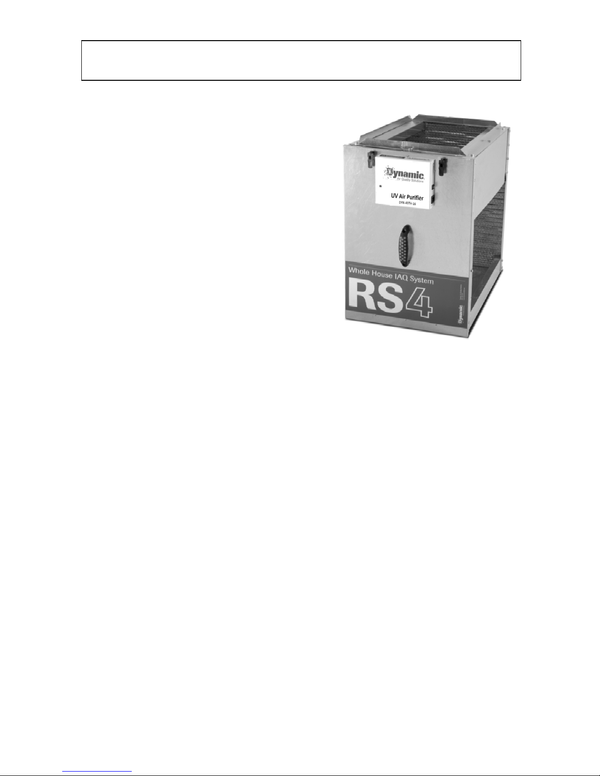
RS4
Whole House
IAQ System
RS4 Whol e House IAQ System
Polarized-Media Electr onic Air Cleaner
Activat e d Ca r bo n M atr i x System
Series2 Germicidal UV Lamp
Note: Read these instructions
carefully before installation
Introduction
Your RS4 Whole House IAQ System is a high efficiency air cleaning system designed to remove
all three types of airborne contaminants: particles, biologicals, and gas phase contaminants. The
large surface areas of the air cleaner and activated carbon help to reduce air veloc it y and static
pressure resistance for more effective filtration.
Section I. Cabinet Installation
1) Turn the thermostat fan switch to the “OFF” position.
2) Turn off power to the furnace/air handler.
3) Remove the existing filter from the furnace/air handler or return air grille.
4) Locate the RS4 cabinet on the return side of the ductwork, adjacent to and upstream of the
blower compartment. This placement will ensure that the furnace blower and cooling coil are
kept clean. Determine the mounting orientation in a location that is readily accessible for
service and maintenance, allowing a minimum of 27” in front of the slide-out access panel.
5) If the cabinet is installe d on a f lat s ur f ace, seat the c ab inet on vibr ati on p ads ( 1/2” minimum) to
provide adequate clearance for the door operation.
6) When securing the RS4 cabinet into the H VAC s ystem , do s o with the c abinet door in plac e to
keep the cabinet plumb. This will ensure that the access door fits properly after installation.
7) The RS4 cabinet uses int erchangeable bl ock-off plates that c an be positioned to allow airflow
through the cabinet at a right-angle or flow-through from side to side or top to bottom.
Mounting holes are provided in the air cleaner cabinet for #10 sheet metal screws or 1/8”
rivets. All system components allow for installation with airflow in any direction.
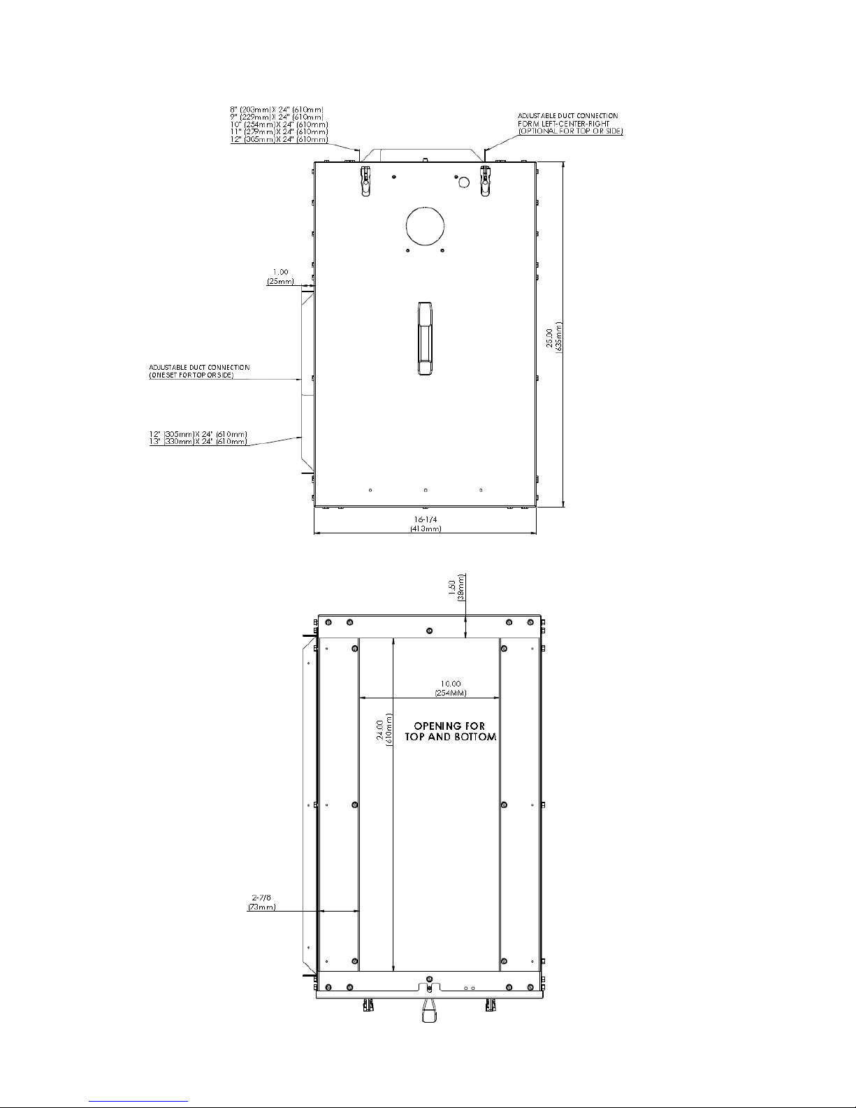
8) The RS4 c abinet includes one set of adjustable duct flan ges that can adjusted to c onnect the
top/bottom 24”x8” duct opening to duct sizes of 24’x8”, 24”x9”, 24”x10”, 2 4”x11”, or 24”x12”.
The cabinet is shipped with top flanges in the 24”x10” center position. T o adjust the flanges,
remove the flange screws, adjust t he flanges to the des ired duct size, and secure w ith scre ws.
Openings on the side of the cabinet m eas ure 23.5” x 13.5”. A dditiona l duct f lange k its for side
connections (part no. RS4-FLANGEKIT) are available as an optional accessory.
1
Page 2
2
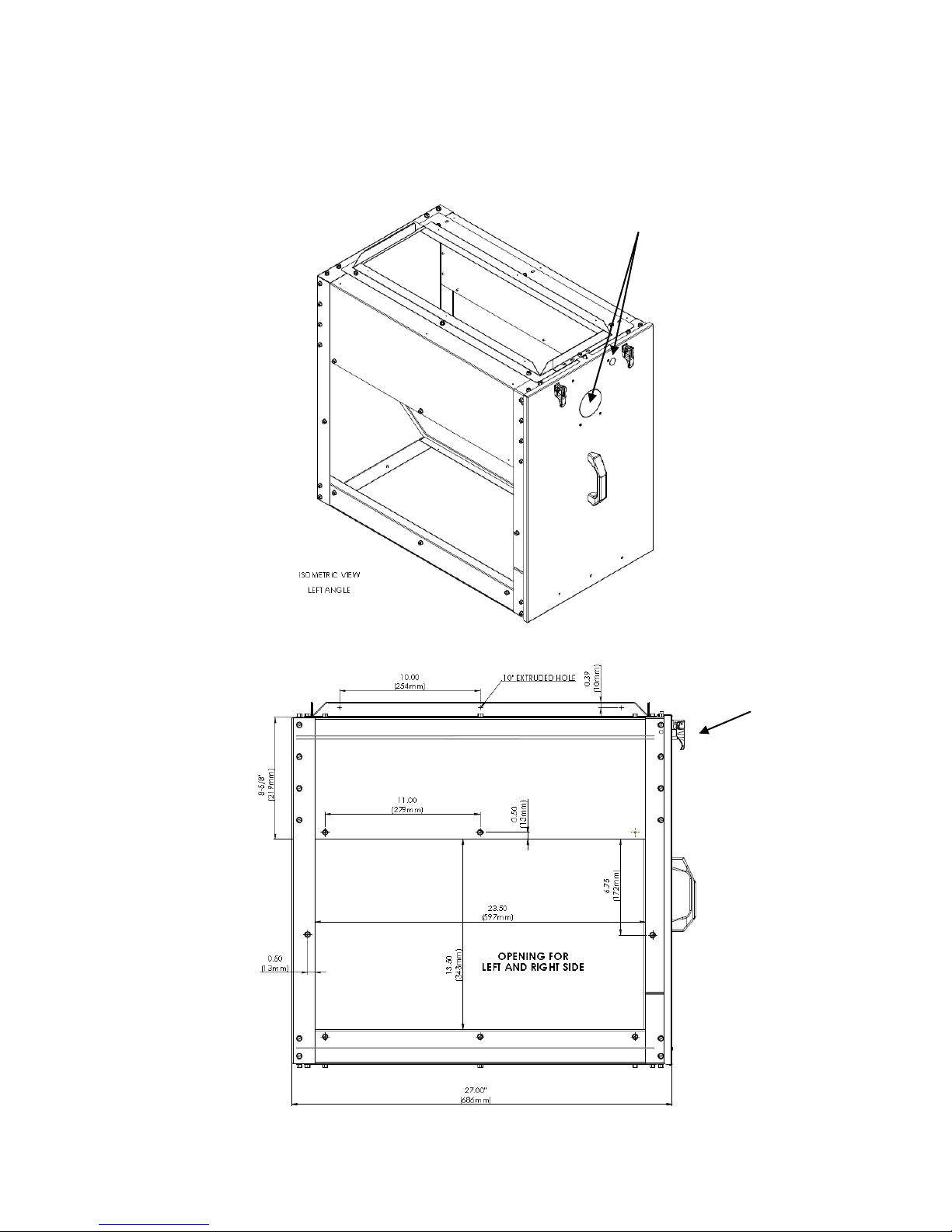
Figure 2 – Side Vie w
Wire inlet
(both sides)
Figure 1
Knock-outs for UV Lamp
& safety switch
9) Holes for wiring access are provided on both sides of the cabinet and a gromm et is provided
for the wiring hole. Onc e t h e c ab ine t h as b een s ec ure d, s ea l al l se ams and holes with foil tape
or mastic so that the cabinet is air tight and UV light cannot escape.
Page 3
3
Figure 2 – Front View
Figure 4 – Top/Bottom View
Figure 3 – Front View
Page 4

4
Section II. Air Cleaner Installation
1) Wiring to an integrated furnace control (IFC) board or on-board transformer:
NOTE: ONLY A QUALIFIED ELECTRICIAN SHOULD PERFORM ELECTRICAL WIRING.
If there is a term inal strip such as the one shown in figure 5, connect the blac k wire of the
power cord to the “Comm on” terminal (typically the " C" terminal) and the black wire with the
white stripe to the “Hot” 24vac terminal (typically the "R" terminal). Output from the 24vac
transformer may vary due to local line voltage fluctuations. Outputs up to 28vac are
acceptable.
Figure 5
If the terminals are unm arked, or to c onfirm the markings, use a voltm eter to find t he Comm on
and “Hot” 24vac terminals:
a. Turn off the power to the furnace/air handler and the transformer.
b. W ith the voltm eter s et to "C ontinu ity", ch eck for c ontinuit y betw een each term inal and th e
metal frame of t he furnace/air h andler. C hoose a sp ot on th e furnace/ air handler such as
a screw or unpainted edge, where a good electrical contact can be found.
c. If continuity is found between one of the terminals and the furnace/air handler, that
terminal will be the Common terminal.
d. With the power on to the transformer, use the voltmeter to locate the 24vac terminal.
If a Common or 24vac ter minal cannot be located, it will be n ecessary to install a separate
transformer. If a hard-wired transformer is used, an isolated class II transformer is
recommended. The transformer must be installed according to local codes and ordinances.
2) Route the power cord to the air cleaner. The cord should be run so that it is not crimped or
abraded and should have enough slack to allow the air cleaner service drawer to be fully
extended for routine maintenance. Position the power cord slack to keep it away from the
furnace/air handler blower and other moving parts.
3) Plug the power cord into the air cleaner once it is securely in place (fig 6).
Figure 6
4) A plug-i n transformer (part number A412402) is available as an optional acces sory to plug
into any 110-Volt (AC) outlet to provide 24-Volt (AC) power to the unit. Do not substitute
other 110vac-24vac transformers. Damage could result to the air cleaner electronics and
void the air cleaner warranty.
Page 5

5
Figure 7. Airflow can
be in either direction
Section III. Carbon Matrix Installation
1) Unlatch and open the empty carbon matrix tray adjacent to the polarized-media air cleaner.
2) Leaving the protective foam border in plac e, carefully place the carbon sections into the tray
as shown below. The carbon matrix should be p ositio ned downs tream of the polar ized-media
air cleaner in order to extend the service life of the carbon.
3) Close and latch the carbon tray. Sec ure the latc h es wit h scr ews (provided) for extra security.
4) Close the cabinet access door and latch securely.
5) Turn on the power to the fur nace/air handler and U V lamp. The thermostat f an switch should
be set to the “ON” position.
6) Affix the caution label and Replacement Record sticker in prominent locations to the cabinet.
IMPORTANT: FOR BEST AIR CLEANING EFFICIENCY AND OPTIMUM COMFORT, THE FURNACE/AIR
HANDLER FAN SHOULD BE RUN CONTINUOUSLY WITH THE FAN SWITCH IN THE “ON” POSITION
RATHER THAN THE “AUTO” POSITION.
Section IV. UV Lamp Installation
1) The model 407H-16 or the 407H-16-O3 Series2 Germicidal UV Lamp is standard on some
models or available separately.
2) Remove the cover from the unit by removing the top and bottom retaining screws using a
screwdriver.
3) Remove the knock-outs on the RS4 cabinet door for UV lamp and safety switch (fig 1).
4) Attach back of the UV unit to the cabinet door using the four ¼” 8-32 screws provided.
5) Attach ¾” 8-32 safety switch screw to cabinet frame (fig 8) to activate safety switch.
6) Remove germicidal lamp holder using a 11/32 size nut driver (fig 9).
7) Slide germicidal lamp into lamp opening and reinstall lamp holder.
8) Plug lamp into lamp connector.
9) Connect power in accordance with local wiring codes. The multivoltage ballast is self-adjusting
and operates with voltages f rom 120 - 240 VAC. Use the provided 120 VAC power cord. For
240 VAC, install 5 amp inline fuses and use the optional 240 VAC power cord, Part #PC-240.
IMPORTANT: WHEN USING THE 407H-16-O3 LAMP WITH ACTIVATED OXYGEN, POWER TO THE
LAMP MUST BE INTERLOCKED WITH THE FURNACE BLOWER.
Page 6

6
Lamp Holder
Safety
Switch
Safety
Switch
10) For 407H-16-O3 ONLY – Plug the 120 VAC power cord into an outlet which is interlocked with
the furnace blower. If an EAC terminal is available, supply power to the outlet from the EAC
terminal. If there is no EAC terminal, interlock the UV unit with the furnace blower using an
appropriate alternate.
11) Verify voltage is operati ng bet ween 120 - 240 VAC when the air handler is operating.
12) Replace and secure cover using the two retaining nuts. Affix caution labels if necessary.
Safety
Switch
Screw
Figure 8 – Safety Switch (si de view) Figure 9 – Lamp Back Mounting Plate
NOTE: CARE SHOULD BE TAKEN TO ENSURE THAT UVC LIGHT DOES NOT SHINE
ON PLASTIC SURFACES INCLUDING WIRING.
Section V. Maintenance – Air Cleaner Media Pads
Air cleaner m edia pads ge nerally last 3 to 4 months, depe nding on house hold cond itions. In
a new installation, however, it is s uggested t hat the medi a pad be insp ected and/or replaced
after one month of operation due to initial cleanup of contaminants. Only GENUINE
replacement media pads shou ld be used with your a ir cleaner. Fa ilure to do s o could caus e
damage to the air cleaner, alter air cleaner performance, and/or void your Warranty.
Replacement media pads are available from your heating and air conditioning contractor.
CAUTION: WHENEVER IN STALLING OR REMOVING THE AIR CLEANER , THE POWER
TO THE FURNACE/AIR HANDLER SHOULD BE TURNED OFF. CARE SHOULD BE
TAKEN NOT TO LET THE JACK TOUCH ANY GROUNDED OR METAL SURFACES.
1) Turn the thermostat fan switch to the “OFF” position.
2) Turn off power to the furnace/air handler.
3) Turn off power to UV air purifier and disconnect power cord (if applicable).
4) Open the access panel on the RS4 cabinet.
5) Unplug the power cord from the air cleaner power supply.
6) Remove the air cleaner from the filter rack.
7) Open the air cleaner latches, carefully remove the old media pad, and discard.
8) Carefully position the new replacement media pad so that it is centered within the air
cleaner frame.
9) Close and re-latch the air cleaner.
10) Return the air cleaner to its location in the filter rack.
11) Plug the power supply cord into the air cleaner once it is securely in place (fig 6).
Page 7

7
12) Close the cabinet access door and restore power to the furnace/air handler and UV air
purifier.
13) Switch the thermostat back to the “ON” position. For optimum results, the furnace or air
handler should be run continuously with the fan switch in the “ON” position, rather than
the “AUTO” position.
14) In damp or humid areas, the new media pad may make a slight snapping sound when first
installed. This is normal and should stop within 24 hours of operation.
WARNING: FAILURE TO CHANGE THE MEDIA PAD ON A REGULAR BASIS COULD REDUCE
AIRFLOW AND CAUSE DAMAGE TO THE H E ATING AND COOLING SYSTEM.
Section VI. Maintenance – Activated Carbon Matrix
Carbon Matrix inserts genera lly last 18000 hours or two years, depending on household conditio ns.
Replacement carbon inser t s are avai la ble from your heating and air condi tio ni ng c ontrac tor .
CAUTION: WHENEVER INSTALLING OR REM OVING THE AIR CL EAN ER, THE POWER TO T HE
FURNACE/AIR HANDLER AND UV AIR PURIFIER SHOULD BE TURNED OFF. CARE SHOULD
BE TAKEN NOT TO LET THE JACK TOUCH ANY GROUNDED OR METAL SURFACES.
1) Turn the thermostat fan switch to the “OFF” position.
2) Turn off power to the furnace/air handler and UV air pur if ier.
3) Open the access panel on the RS4 cabinet.
4) Unplug the power cord from the air cleaner power supply.
5) Remove the air cleaner from the filter rack.
6) Open the air cleaner latches, carefully remove the old carbon inserts and discard.
7) Position the new carbon inserts so that they are centered within the frame (fig 7).
8) Close and re-latch the air cleaner.
9) Return the air cleaner to its location in the filter rack.
10) Plug the power supply cord into the air cleaner once it is securely in place (fig 6).
11) Close the cabinet access door and restore power to t he furnace/air handler and UV air
purifier.
12) Switch th e thermos tat back to the “ON” position. F or optimum results, the furnac e or air
handler should be run continuous ly with the fan switch in the “ON” pos ition, rather than
the “AUTO” position.
Section VII. Maintenance – UV Air Purifier
Series2 UV lamps are designed to last 18000 hours or two years, depending on household
conditions but should be cleaned after 9000 hours (1 year) of operation.
1) Cleaning Instructions:
a. Turn off power and disconnect power cord to the UV air purifier.
b. Remove the cover from the unit by removing the top and bottom retaining screws using a
screwdriver.
c. Unplug the lamp connector from the end of the lamp.
d. Remove lamp holder using a 11/32 size nut driver. (Figure B)
e. Remove the lamp by grasping the plastic end cap and extract carefully.
f. Using a soft cloth moistened with rubbing alcohol, wipe down the lamp. If there is a large
build-up of dust particles, you may wish to use a can of air first. Always handle lamp by
the end caps.
g. Slide the lamp back into lamp opening by grasping the plastic end cap and reinstall lamp
holder.
Page 8

8
h. Plug the lamp into the lamp connector.
i. Replace and secure the cover using the two retaining nuts.
j. Plug power cord back into outlet, or restore power to unit.
2) Replacing the UV Lamp:
a. Replacement lamps are available from your heating and air conditioning
contractor and should be replaced after every 18000 hours (2 years) of operation.
Follow the same steps as above, excluding step f.
Section VIII. Replacement Parts
1) Maintenance is limited to periodic rep lacement of th e air cleaner m edia pads, typically every
3 to 4 months. Activ ated carbon inserts and Series2 UVC lam ps should be replaced e very
18,000 hours, or every two (2) years. Use only GENUINE replacement parts.
2) Replacement parts can be ordered from your heating and air conditioning contractor . Have
the model number or unit size available when calling.
Filter Box Parts
Item Description
1 Door Assy
2 Door Handle
3 Door Clip
4 Front Frame Assy
5 Door Lock Nut
6 Block off plate
7 Bottom Angle
8 Top Angle
9 Back Cover
10 Flange Assembly
Air Cleaner / Carbon Tray
Item Description
1 Media Pad
2 Power Head
3 Po wer Cord
4 Insulator Button
5 Latch
6 Indicator Light
7 Input Jack
8 Hinge
9 Frame
10 Corner
11 Screen
12 Spline
13 Warning Label
14 Brand Label
15 Patent Label
16 Size Label
17 Carbon Tray Latch
18 Carbon Inserts (4)
19 Track
FOR TECHNICAL SUPPORT CALL (800) 578-7873
Specifications are subject to change without not ice
©2013 Environmental Dynamics Group GEN-212 (7/14)
 Loading...