

Page 1
Polarized-Media
Electronic Air Cleaner
Installation
Instructions
&
Consumer
Information
Section I. Installation Instructions
1) Turn the thermostat fan switch to the “OFF” position.
2) Turn off power to the furnace/air handler.
3) Remove the existing filter from the furnace/air handler or return air grille.
4) Wiring to the on-board transformer or integrated furnace control:
NOTE: ONLY A QUALIFIED ELECTRICIAN SHOULD PERFORM ELECTRICAL WIRING.
If there is a terminal strip such as the one shown in figure 1, connect the black wire of the power
cord to the “Common” terminal (typically the "C" terminal) and the black wire with the white stripe
to the “Hot” 24vac terminal (typically the "R" terminal). Output from the 24vac transformer may
vary due to local line voltage fluctuations. Outputs up to 28vac are acceptable.
Figure 1
If the terminals are unmarked, or to confirm the markings, use a voltmeter to find the Common
and “Hot” 24vac terminals:
a. Turn off the power to the furnace/air handler and the transformer.
b. With the voltmeter set to "Continuity", check for continuity between each terminal and the
metal frame of the furnace/air handler. Choose a spot on the furnace/air handler such as
a screw or unpainted edge, where a good electrical contact can be found.
c. If continuity is found between one of the terminals and the furnace/air handler, that
terminal will be the Common terminal.
d. With the power on to the transformer, use the voltmeter to locate the 24vac terminal.
Page 2
If a Common or 24vac terminal cannot be located, it will be necessary to install a separate
transformer. If a hard-wired transformer is used, an isolated class II transformer is recommended.
The transformer must be installed according to local codes and ordinances.
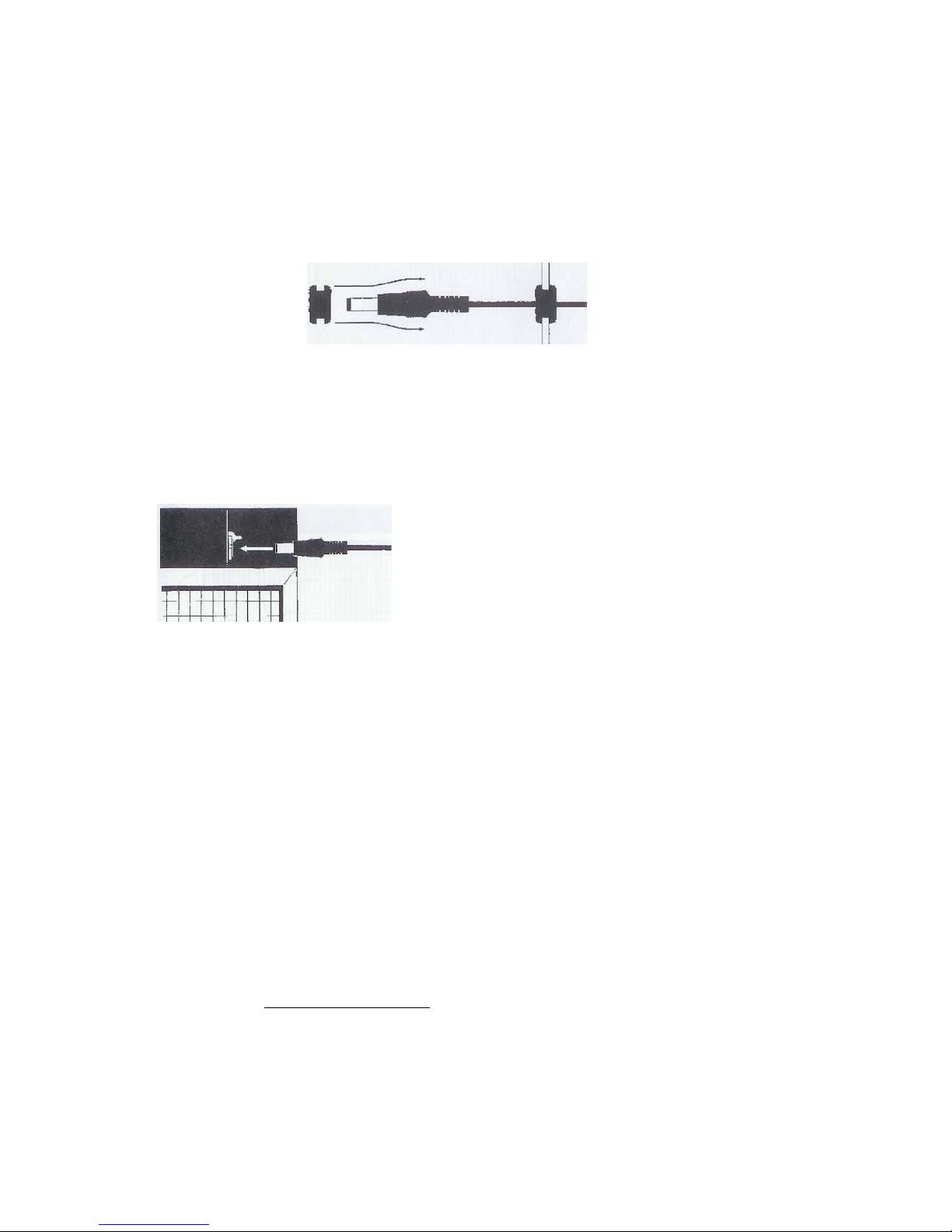
5) If necessary, route the power cord through the furnace/air handler cabinet to the filter rack
area. If an existing access hole is not available, drill a 7/16” hole. A grommet is provided to fit a
7/16"
hole (fig 2). The cord should be run so that it is not crimped or abraded and should have
enough slack to allow the air cleaner to be easily removed for routine maintenance. Position the
power cord slack to keep it away from the furnace/air handler blower and other moving parts.
Figure 2
6) Install the air cleaner into the filter rack or return air grille.
7) Plug the power cord into the air cleaner once it is securely in place (fig 3).
Close the filter access door or grille.
8)
9) Turn on the power to the furnace/air handler. The power indicator light on the air cleaner
should illuminate.
10) Turn the thermostat fan switch to the “ON” position.
Figure 3
11) If arcing occurs within the air cleaner, see the instructions in section III for replacing the air
cleaner Media Pad.
12) Affix the caution sticker and Media Pad Replacement Record in a prominent location near the
air cleaner.
Section II
. Optional Plug-In Transformer
NOTE: For best air cleaning efficiency and
optimum comfort, the furnace/air handler
blower should be run continuously with the
fan switch in the “ON” position rather than in
the “AUTO” position.
As an optional accessory, a plug-in transformer (part no. A412402) is available to plug into any
110-Volt (AC) outlet to provide 24-Volt (AC) power to the unit.
WARNING: DO NOT SUBSTITUTE OTHER 110VAC–24VAC TRANSFORMERS AS DAMAGE
COULD RESULT TO THE UNIT ELECTRONICS AND VOID THE AIR CLEANER WARRANTY.
Section III. Maintenance and Media Pad Replacement
Replacement Media Pads are available from your heating and air conditioning contractor or by
ordering online at
WARNING: WHENEVER INSTALLING OR REMOVING THE AIR CLEANER, THE
POWER TO THE FURNACE/AIR HANDLER MUST BE TURNED OFF. CARE SHOULD
BE TAKEN NOT TO LET THE JACK TOUCH ANY GROUNDED OR METAL SURFACES.
ALTHOUGH THE JACK IS SHIELDED, IT IS POSSIBLE FOR THE CENTRAL POWER
INSERT TO CONTACT GROUND WHICH COULD RESULT IN DAMAGE TO THE
TRANSFORMER OR ELECTRONICS.
www.DynamicAQS.com.
2
Page 3

1) Turn the thermostat fan switch to the “OFF” position.
2) Turn off power to the furnace/air handler.
3) Open the filter access door or grille.
4) Unplug the power supply cord from the air cleaner
powerhead.
5) Remove the air cleaner from the filter rack or return
air grille.
6) Open the air cleaner (fig 4), remove the old media pad
and discard.
7) If dust has accumulated on the outer screen of the air
cleaner, clean with a dry brush or vacuum.
8) Position the new replacement media pad so that it is
centered within the air cleaner frame(fig 5).
9) Close and re-latch the air cleaner.
10) Return the air cleaner to its location in he furnace/air
handler or return air grille.
11) Plug the power supply cord into the air cleaner once
it is securely in place (fig 6).
12) Close the filter access door or grille.
13) Switch the thermostat back to the “ON” position. For
optimum results, the furnace or air handler should be run
continuously with the fan switch in the “ON” position,
rather than the “AUTO” position.
14) Because of variations in humidity and temperature,
the new media pad may make a slight snapping sound
when first installed. This is normal and should stop within
24 hours of operation.
Figure 6
NOTE: Media pads generally last 3 to 4 months, depending on household conditions. In a new
installation, however, it is suggested that the media pad be inspected and/or replaced after one
month of operation due to the initial cleanup of contaminants.
Figure 4
Figure 5
WARNING: FAILURE TO CHANGE THE MEDIA PAD ON A REGULAR BASIS COULD REDUCE
AIRFLOW AND CAUSE DAMAGE TO THE HEATING AND COOLING SYSTEM.
Section IV. Replacement Parts
1) Maintenance is limited to periodic replacement of the air cleaner media pads. This is typically
done every 3 to 4 months.
2) Replacement Media Pads can be ordered from your heating and air conditioning contractor or
by ordering online at
when calling. Refer to the size label on the unit (item 12 in figure 7) for the unit size. Air cleaner
media pads are sized according to the size of the overall air cleaner and NOT the size of the
media pad itself.
3) When giving dimensions, the first dimension given should be the length of the side with the
powerhead.
www.DynamicAQS.com. Have the model number or unit size available
3
Page 4

Item Description
1 Replacement Media Pad
2 Powerhead (inside channel)
3 Power Cord
4 Electrode Insulator Button
5 Air Cleaner Latch
6 Power ON Light
7 Label “Unplug before Opening”
8 Power Input Jack
9 Label
10 Electrode
11 Model / Power Rating Label
12 Air Cleaner Size Label
13 Patent Label
14 Hinge
15 Screen
16 Frame
17 Spline
FOR TECHNICAL SUPPORT
Figure 7
Call 1-800-578-7873
Dynamic Air Quality Solutions
P.O. Box 1258
Princeton, NJ 08542
Tel: (800) 578-7873
Fax (609) 924-8524
www.DynamicAQS.com
Specifications are subject to change without notice. Dynamic and Dynamic
Air Quality Solutions are registered trademarks of Environmental Dynamics
Group, PO Box 1258, Princeton, NJ 08542
©2005 EDG DYN-101 (01/06)
4
 Loading...