

Page 1
No. 60025, Issue 5. January 1999
TM
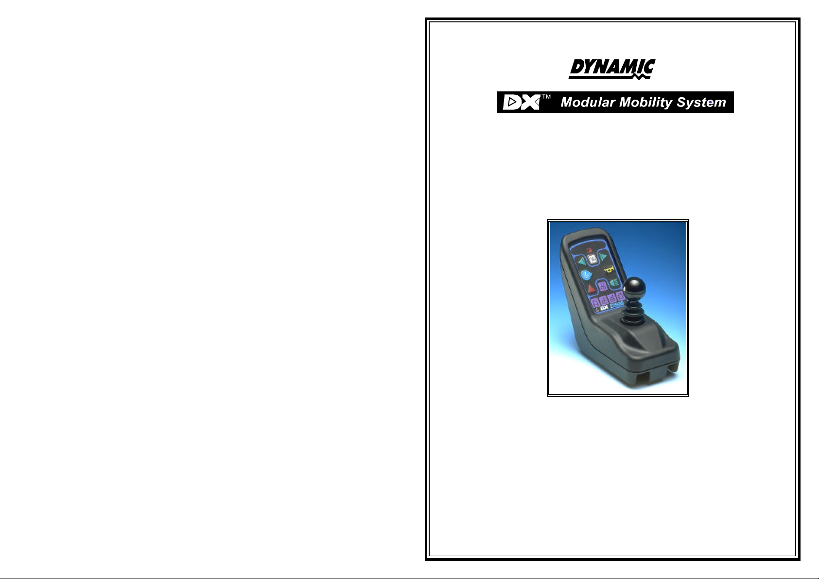
DX Dolphin Remote
(DX-Rem34)
Installation Manual
Order/Part Number for this Manual : GBK60025 issue 5
Important Notes
1. Read this Manual carefully before installing or operating your DX control system.
2. Due to continuous product improvement Dynamic reserves the right to update this Manual.
3. Any attempt to gain access to or in any way abuse the electronic components and
This Manual supersedes all previous issues which must not continue to be used.
associated assemblies that make up the wheelchair control system renders the
Manufacturer’s Warranty void and the Manufacturer free from liability.
Page 2

No. 60025, Issue 5. January 1999
Contents
1 Introduction ................................................. 1
2 Related Documentation ....................................... 2
3 Features .................................................... 3
4 Specifications ............................................... 5
Electrical ................................................ 5
Mechanical .............................................. 5
Environmental ............................................ 6
5 Operation ................................................... 7
On/Off and Key Lock system ................................ 7
Arming/Disarming the locking system ..................... 7
Using the system without the lock ........................ 7
Joystick OONAPU ........................................ 7
Drive Program Selection and Display .......................... 8
Profile Selection ..................................... 8
Drive Program Display ................................ 8
Drive Inhibit Display .................................. 8
Remote Status Display ................................ 8
System Status LED ................................... 8
Lighting Control .......................................... 9
Actuator Control .......................................... 9
Battery Gauge Display .................................... 10
6 Installation and Testing ...................................... 11
Attention: If replacing existing Power Wheelchair Controller ........ 11
Compatibility with Power Wheelchairs ........................ 11
DX Dolphin Mounting ..................................... 12
DX Dolphin Connection with the DX System ................... 13
Testing ................................................ 14
Powering Up Method ................................ 14
Power Up Response ................................. 14
DX Dolphin Check Sequence .......................... 14
7 Batteries and Charging ...................................... 15
Battery Type ............................................ 15
Battery Charging ......................................... 15
Battery Gauge ........................................... 16
Battery Saver ............................................ 16
Page 3

No. 60025, Issue 5. January 1999
Battery Condition Warnings ................................ 17
Battery High warning condition ......................... 17
Battery Low warning condition ......................... 17
Low Capacity warning condition ........................ 18
8 Programming ............................................... 19
Introduction ............................................. 19
Default Programs ......................................... 19
Auto Download .......................................... 20
Programming Tools ....................................... 21
Dynamic Wizard .................................... 21
HHP ............................................. 22
Wizard High Volume Programming ........................... 22
Example .......................................... 22
DX Dolphin Wizard Programming ............................ 24
Drive Program Parameters ............................. 24
Keypad and Speed Pot Parameters ...................... 28
Joystick Parameters .................................. 30
Actuator Parameters ................................. 32
Lighting Parameters .................................. 36
DX Dolphin HHP Programming ............................. 37
Initial Operation .................................... 37
Test Driving and Saving Changes ....................... 38
To View / Adjust Drive Programs ....................... 38
To Adjust Joystick Source ............................. 39
Reverse Joystick - Forward / Reverse .................... 39
To Enable Technician Mode ........................... 40
Joystick Calibration .................................. 40
Combined Lighting Actuator Module (CLAM) Enable ....... 41
Lighting Module (LM) Enable .......................... 42
9 Diagnostics and Fault Finding ................................ 43
Flash Code ............................................. 43
Limp Mode ............................................. 47
Wizard Diagnostics ....................................... 48
To View Diagnostics ................................. 48
Status Report ............................................ 48
To View Status Report ............................... 48
Chair Log .............................................. 49
To View Chair Log .................................. 49
10 Product Disclaimer .......................................... 52
11 Electromagnetic Compatibility (EMC) .......................... 53
Page 4

No. 60025, Issue 5. January 1999
12 Maintenance ............................................... 54
13 Safety and Misuse Warnings .................................. 55
14 Warranty ................................................... 57
15 Sales and Service Information ................................ 58
16 Appendix A : Abbreviations .................................. 59
17 Appendix B : Change Record ................................. 61
18 Anhang C : Deutschsprachige Warnhinweise ................... 62
Page 5
No. 60025, Issue 5. January 1999
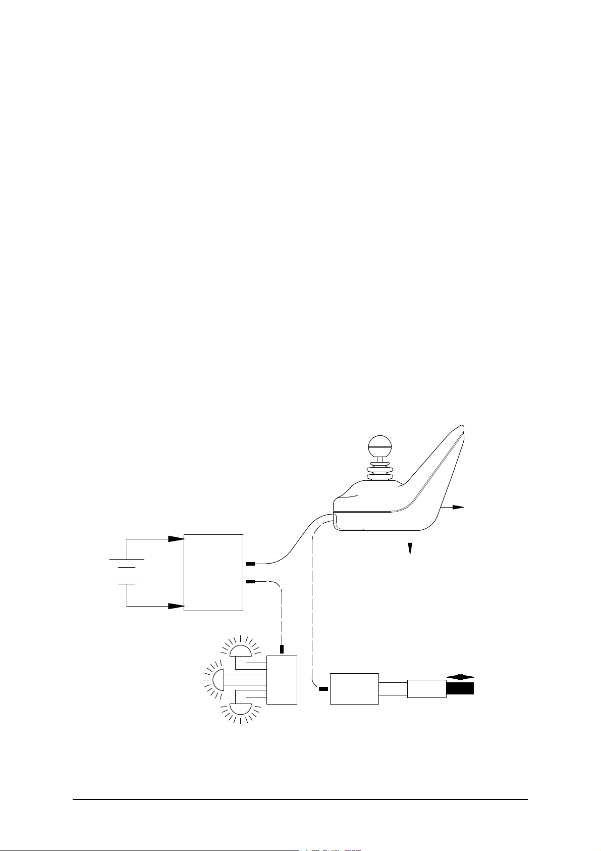
1 Introduction
The DX Dolphin Remote is a DX compatible remote supplied by Dynamic
Controls Ltd. As well as driving, this DX Remote has switches for selecting
up to five actuators, which can then be operated under joystick control. A
battery gauge, side lights, indicator lights, hazard lights, magnetic key and horn
are also supported. Up to five individual Drive Programs or profiles are
available, and the currently selected program is displayed.
This DX Remote has two standard DXBUS connectors so that it may be
connected to the DX System.
The DX Dolphin Remote and the associated DX Power Module are fully
programmable to cater for a wide range of chair types and user needs. Correct
installation and programming are essential to ensure optimum performance and
safety.
This manual and others listed below must be read and understood. For more
information contact Dynamic Controls Ltd or an agent as listed in section14.
Example DX System
DX Pow er
Module
24V
Wheelchair
Battery
Right Indicator Lights
DX Dolphin
(DX-REM34)
DXBUS
Optional DXBUS
To Battery
Charg er
To HHP
or Wizard
Optional DXBUS
1 Introduction
Side Lights
Left Indicator Lights
DX-LM
Example
DX Module
Actuator
DX-TAM
Example
DX Module
1
Page 6

No. 60025, Issue 5. January 1999
2 Related Documentation
A DX based wheelchair control system may comprise between two and
sixteen DX compatible modules depending on the application. Each DX
compatible module has its own Installation Manual which describes the
installation requirements of that particular module.
This Manual describes installation of the DX Dolphin Remote only and must
therefore be read in conjunction with the :
! DX Power Module (PMB) Installation Manual
! DX Hand Held Programmer (HHP) Manual
! Dynamic Wizard Installation Sheet / Online Help
! Installation Manuals for all other DX Modules to be used in your
application.
2
Related Documentation 2
Page 7

No. 60025, Issue 5. January 1999
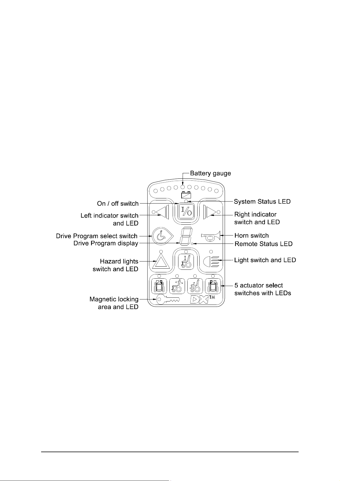
3 Features
Joystick Normally used for controlling wheelchair speed and
direction. Can also be used for actuator control
when any of the 5 actuators have been selected.
On/off switch / Toggles the entire DX control system between the
On and Off modes.
System Status LED The System Status LED indicates the On/Off status
of the system. It also flashes to indicate system
faults. (Refer to Diagnostics section 9 for Fault
Codes details.)
Remote Status LED The Remote Status LED indicates the status of the
Dolphin as an individual DX Module. If it is
flashing, there is a fault within the Dolphin.
Battery gauge Battery charge level is indicated by a set of ten
LEDs. These are arranged in an arc from left to right
as three red, four orange, and three green.
Actuator select A separate switch for each set of seat raise/lower,
switches (x5) seat tilt, back tilt, left leg rest and right leg rest, each
with its own LED indicator. Once selected, actuator
operation is activated using the joystick.
Drive Program A switch is used to cycle through and select one of
select switch the five Drive Programs.
Drive Program A seven segment display for showing the currently
Display selected Drive program.
Lighting controls Separate push switches for the control of lights,
indicators, and hazard, each with its own LED.
Horn switch Activates horn while pressed if system power is on.
Magnetic key lock Magnetic key may be used to "lock" the DX System
to prevent unauthorised use (see later details).
3 Features
3
Page 8
No. 60025, Issue 5. January 1999
Programming socket A standard HHP / Wizard socket.
HHP / Wizard socket
Standard DXBUS For connecting the DX Remote, with a DXBUS
Connection (x2) cable for connection to other DX compatible
modules.
Battery charger Standard 3 pin XLR type battery charger socket.
socket
Fully functional keypad
4
Features 3
Page 9
No. 60025, Issue 5. January 1999
4 Specifications
Electrical
Compatible with standard DXBUS
Operating voltage range 18V - 32 V d.c.
Charger rating 12 A RMS continuous, limited by
DXBUS rating.
Quiescent Current <1mA Off, typically 100mA On
Mechanical
Weight: 0.59 Kg
Mounting: As per Installation section 6, Mounting
Case material: Injection moulded plastic, Noryl N90 flame
retardant
147mm
Two DXBUS
connectors
85mm
Joys tick
182mm
Keypa d
Horn g rill
Cove red
charger socket
4 Specifications
Programmer s ocket
5
Page 10

No. 60025, Issue 5. January 1999
Environmental
Parameter Min Max Units
Operating ambient temperature range -25 50 °C
Storage temperature range -25 70 °C
Operating and storage humidity 0 90 %RH
Environmental Rating IP54
RFI Emissions CISPR 11, Class B.
ESD ISO7176 part 21
Durability ISO7176 part 14 (pending).
Vibration Specification BS2011: part 2Fd and BS7527: section 3.5,
class 5M3.
Complies with environmental standard : prEN12184.
6
Specifications 4
Page 11

No. 60025, Issue 5. January 1999
5 Operation
On/Off and Key Lock system
The On/Off button toggles the system power on or off provided the DX
Remote is not locked.
The Key Lock system uses a magnetic key to power the wheelchair down in
such a way to prevent subsequent unauthorised power up and driving. This
function is required for TÜV approval and operates as follows :
Arming/Disarming the locking system
To arm the locking system hold the magnetic key on or near the key symbol
on the DX Remote front panel. The system will beep and automatically power
itself down and no LEDs should be lit.
To turn the chair back on press the On/Off button. This will cause the system
to power up but the chair needs to be disarmed before it can be driven - this
waiting to be disarmed state is indicated by the flashing key symbol.
To disarm the lock put the magnetic key on or near the key symbol - this will
cause the key to stop flashing and the chair may now be driven normally. If the
wheelchair is not disarmed within one minute, the Dolphin will automatically
turn itself off.
Using the system without the lock
If locking the chair is not required simply power the chair down by pressing the
On/Off button - all indicators will go out.
To turn the system back on press the On/Off button - the system is now able
to be driven without the use of the magnetic key.
Joystick OONAPU
All DX Remotes feature Out Of Neutral At Power Up (OONAPU) detection.
If the system is powered up while the joystick is not in the neutral position, or
an inhibit condition such as a battery charger is removed, the System Status
LED flashes rapidly for either as long as the condition persists or for a
maximum of 5 seconds.
If the condition persists, after 5 seconds a DX Module Fault (Flash Code 1) is
signalled on the System Status LED, and the Remote Status LED flashes. This
is a latching fault and must be cleared by powering the system down and up
again (with the joystick in neutral).
5 Operation
7
Page 12

No. 60025, Issue 5. January 1999
An OONAPU fault is also generated if the joystick source is changed. This
occurs when the Attendant / User switch on the DX-ACU is toggled or the
Drive Program is changed causing a joystick swap, while the joystick is not in
the neutral position. In these situations the fault is non-latching and the system
does not need to be powered down to clear the fault.
Drive Program Selection and Display
The Dolphin can offer up to five different Driving Programs, depending on its
configuration. (See Programming section.)
Profile Selection
Profiles can be selected using the Drive Program Select switch. Pressing this
switch will increment the Drive Program number up to the maximum
configured value. A further switch press will return the Dolphin to Profile 1.
Drive Program Display
The current Drive Program number is displayed on the 7-segment Drive
Program Display. When the ACU has control of the wheelchair, this display
is blank.
Drive Inhibit Display
A '-' is displayed on the Drive Program Display whenever the DX System is in
Drive Inhibit state, e.g. during battery charging, operation of actuators, active
Stop Switch (CLAM or TAM).
Remote Status Display
The Remote Module Status is displayed beside the 7-segment Drive Program
display. This LED will flash if there is an internal DX Remote fault, or if an
OONAPU fault has occurred.
System Status LED
The System Status LED is displayed above the On/Off switch. This LED is lit
if the system is turned on. It also flashes in groups called Flash Codes, to
indicate system faults.
8
Operation 5
Page 13
No. 60025, Issue 5. January 1999
Lighting Control
A set of four lighting control switches, with feedback LED's, are provided to
control the Lighting System. A lighting module must be installed and enabled.
Suitable modules include: DX Combined Lighting Actuator Module (CLAM);
a DX Lighting Module (LM); or a DX Servo Lighting Module (SLM).
The Light switch toggles on or off the Head/Tail/Sidelight output,
independently of any other switch (except the On / Off switch). The Light
switch LED is lit when the lights are activated.
The Left or Right Indicator switch flashes the appropriate indicator output.
These are turned off by either pressing the same Indicator switch again, or
pressing the other Indicator switch, or the Hazard switch. Each associated LED
is lit when its matching Indicator switch is active.
The Hazard switch flashes both indicator outputs concurrently. The Hazard
LED also flashes if the Hazard LED is enabled. (See Programming section.)
The Hazard Indication can only be cancelled by pressing the Hazard switch
again.
All lighting functions will only operate with the system power on. Refer to the
relevant Installation Manual (e.g. LM or CLAM) for further lighting details.
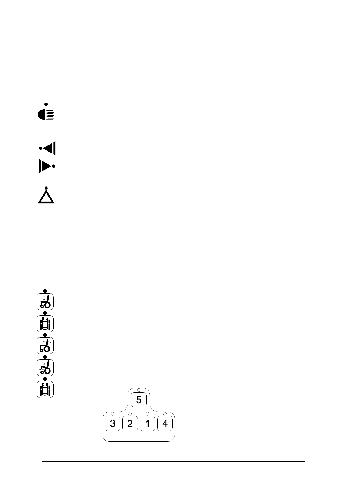
Actuator Control
The DX Remote supports the control of up to five actuators if a correctly
configured actuator control module is present (see Programming section). For
example, a Combined Lighting Actuator Module (CLAM) can drive five
actuators or a Two Actuator Module (TAM) can drive two actuators.
The Dolphin has a set of five Actuator Select switches. Pressing an Actuator
Select switch will inhibit driving and select the appropriate actuator output as
indicated by the adjacent LED. The actuator order assigned in the Wizard as
Actuator 1, 2, 3, 4 and 5 Enable, is arranged on the Dolphin keypad as follows:
5 Operation
9
Page 14
No. 60025, Issue 5. January 1999
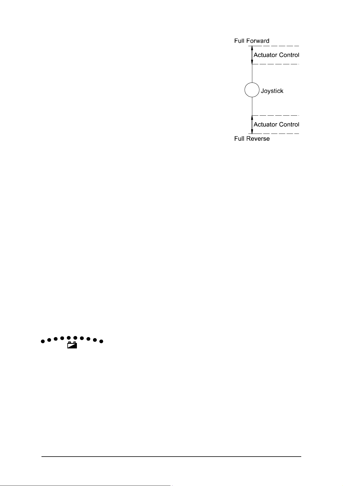
The actuator may then be adjusted up or down with
the Joystick, by deflecting the Joystick beyond half
travel in the forward / reverse axis.
To resume driving, press the current Actuator Select
switch again to deselect. Alternatively another
actuator may be selected directly.
If the user attempts to change modes (e.g. from
driving to actuator mode) while the Joystick is
deflected, the current mode will be terminated and
the Joystick must be returned to neutral position
before the newly selected mode will operate.
The Joystick Actuator parameter must be set to ‘yes’ and the Actuator While
Drive parameter must be set to ‘no’ if actuators are to be controlled with the
Dolphin Joystick, (See Programming section). An Actuator Remote Control
(ARC) can be used to control the actuators. If an ARC is used to control the
actuators the Actuator Select switches on the Dolphin are disabled and the
Joystick Actuator parameter should be set to ‘no’.
The above information is for normal, intended operation of actuators by the
Dolphin. Other options for actuator operation are possible, dependant on
programming. See the TAM Installation Manual for full explanations.
Refer to the relevant DX Module Installation Manual for further actuator
details.
Battery Gauge Display
Battery charge level is continuously indicated by a set of ten LED's. These are
arranged in an arc from left to right as three red, four orange and three green.
The Battery Gauge provides true, useable battery capacity information, and
indicates other related battery conditions. Full battery capacity is indicated by
all ten LEDs on.
10
Operation 5
Page 15

No. 60025, Issue 5. January 1999
6 Installation and Testing
Attention: If replacing existing Power Wheelchair Controller
The model DX joystick/controller recently installed by your home care dealer,
has been designed to function and perform in the same manner as the
joystick/controller you may have already become accustomed to. If properly
installed and programmed, you should notice no difference in the manner in
which your wheelchair performs.
Should your wheelchair not perform as expected, or if you are not satisfied
with its performance, immediately contact the home health care dealer who
performed the installation, or contact Invacare Technical Services Department
at (800) 333-6900.
Compatibility with Power Wheelchairs
The model DX Series power wheelchair controller will function on those
wheelchairs equipped with the following specifications:
! Motor resistance from 0 to 0.5 ohms;
! Motor voltage from 20V to 30V;
! Batteries greater than 20Ahr lead acid;
! Motor current 60 - 80 Amp maximum;
! 12V or 24V parking brake;
(Note: 12V motors can be used if the controller is programmed to half speed)
Note : This controller is not designed for use with specialty type power
wheelchairs, such as stair climbing wheelchairs or stand up wheelchairs.
6 Installation and Testing
11
Page 16
No. 60025, Issue 5. January 1999
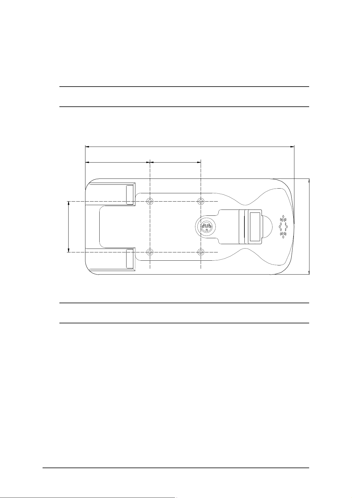
DX Dolphin Mounting
The DX Dolphin Remote can be mounted on either side of the wheelchair, in
an upright position, using four M4 screws.
Warning : For safe installation, select a screw length that protrudes between
4mm and 10mm into the case.
Dimensions of the mounting positions are shown below.
185mm
57mm 45mm
45mm
Note : If the programmer socket needs to be accessible when the DX
Remote is mounted, make allowance for this prior to fitting.
85mm
12
Installation and Testing 6
Page 17
No. 60025, Issue 5. January 1999
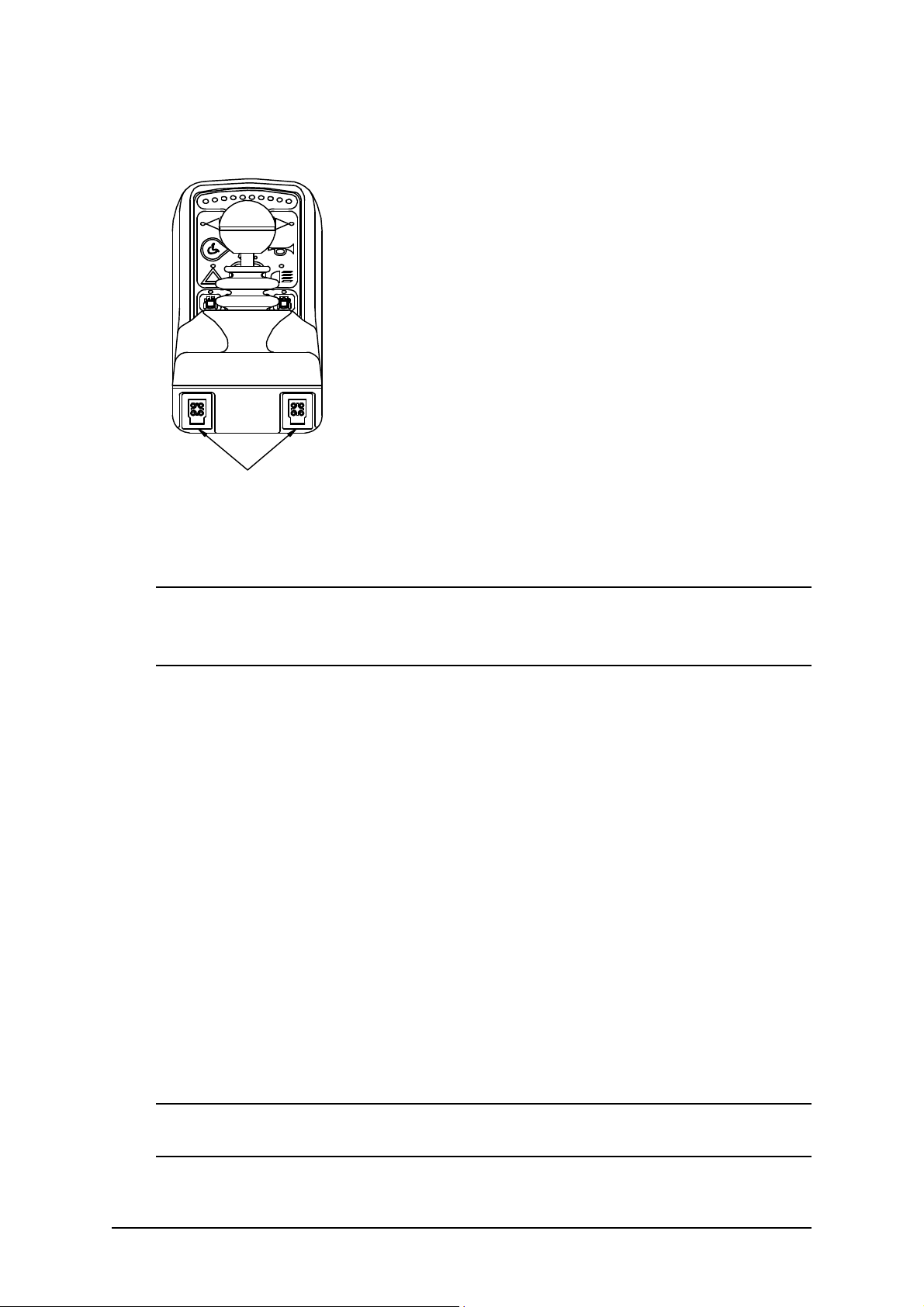
DX Dolphin Connection with the DX System
The Dolphin has two DXBUS connectors which
enables any DXBUS cable to be used to interconnect
it to the remainder of the DX system.
The Dolphin will normally be connected directly to
one of the two PM DXBUS connectors.
Two DXBUS
connectors
Note : If only one DXBUS connector is used on the Dolphin and the
remaining connector is accessible to the wheelchair user, a dummy connector
should be fitted to the unused connector. This will comply with ISO7176.
The DXBUS cables are available in the following standard lengths:
DXBUS Cable, Straight, 0.12 M Part/Order Number GSM 630012
DXBUS Cable, Straight, 0.3 M Part/Order Number GSM 63003
DXBUS Cable, Straight, 0.5 M Part/Order Number GSM 63005
DXBUS Cable, Straight, 1.0 M Part/Order Number GSM 63010
DXBUS Cable, Straight, 1.5 M Part/Order Number GSM 63015
The DXBUS is also available with a ferrite.
DXBUS Cable, Ferrite, 2.0 M Part/Order Number GSM 63020F
Other cable lengths in multiples of 0.1 m are available on request.
Warning: Any protruding screws should be either plastic or plastic coated to
prevent short circuits occurring with the DXBUS Cable pins.
6 Installation and Testing
13
Page 18

No. 60025, Issue 5. January 1999
Testing
Ensure that all DX Modules used in your DX System have been installed as
specified in their Installation Manuals. The Dolphin needs to be correctly
programmed for the appropriate wheelchair prior to testing.
A DX Remote contains the complete wheelchair system set up, from which all
DX Modules download their relevant information when the DX System is first
turned on. Refer to the later Auto Download section.
Powering Up Method
Power up the Dolphin by pressing the On/Off switch.
Power Up Response
The power up response for the Dolphin is :
! The System Status LED will come on steady.
Note : The first time the Dolphin is turned on, the System Status LED will
flash a fault. This is because the Dolphin must download its information to the
DX Power Module . Turn the Dolphin off then on to clear this fault. Refer to
the later Auto Download section.
! At least one of the LEDs on the Battery gauge will be on.
! The Mode display will indicate a number from 1 - 5.
DX Dolphin Check Sequence
Perform the following Dolphin check sequence :
1. Press the On/Off switch again and check the Power LED turns off. Press
it again to turn it on.
2. Press the Drive Program select switch a number of times. Check that the
display changes as expected.
3. Check all Lighting Buttons operate correctly.
4. Check the Key Lock system operates correctly.
5. Perform the remainder of the tests as outlined in the Testing sections of the
Installation Manuals of all other DX Modules used on the wheelchair.
14
Installation and Testing 6
Page 19
No. 60025, Issue 5. January 1999
7 Batteries and Charging
Battery Type
The DX System is designed to perform optimally with either Lead-Acid or Gel
Cell 24 V deep cycle batteries, rated at 20 - 120 Amp hours. The maximum
average discharge rate must not exceed half the rated capacity, in Amp hours.
High continuous discharge rates dramatically reduces the available battery
capacity. For example, at a discharge rate equal to the rated capacity, the
available capacity is 50 - 60 %. At a discharge rate of half the rated capacity,
the available capacity is 70 - 80 %..
A wheelchair that draws maximum average battery current of 20 A, requires
a battery of at least 40 Amp hours. A battery of only 20 Amp-hours, would
begin to suffer a drop in performance at about half of its available capacity.
The 40 Amp hour battery would have a full performance range of 4.5 times
greater than the 20 Amp hour battery; a 80 Amp hour battery would only
increase this range by 2.5 when compared to a 40 Amp hour battery.
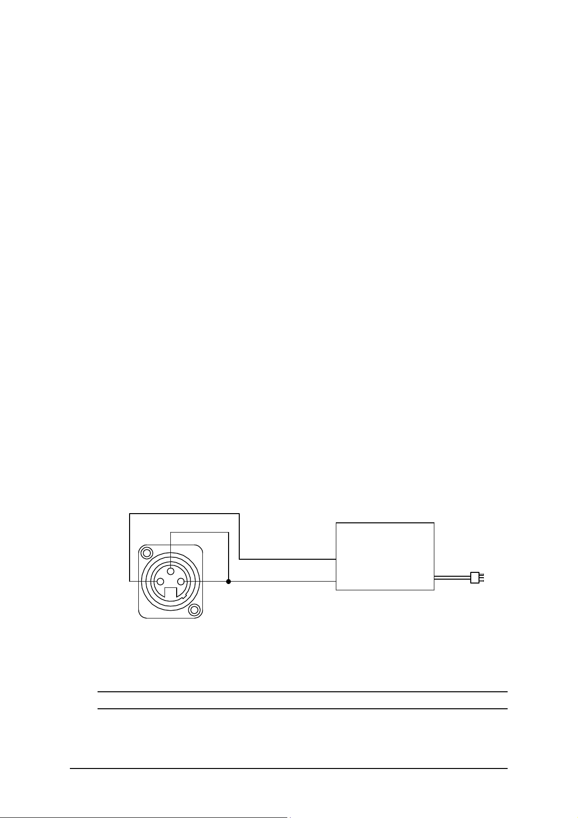
Battery Charging
The battery charger socket is a 3 pin XLR type with pin configuration as
shown below. Ensure that the charger used is compatible with this pin out
before connection.
Inhibit
3
2
1
Battery Cha rger Plug
front view
Battery +
Battery -
Battery Ch arger
Note : The inhibit is shorted to B- on the Battery Charger plug.
7 Batteries and Charging
15
Page 20

No. 60025, Issue 5. January 1999
The wheelchair is automatically disabled from driving whenever the battery
charger is plugged in. The Drive Program will show ‘ ’ to indicate that the
wheelchair is inhibited.
Connection of the battery charger will automatically power the wheelchair, if
the wheelchair was powered down at the time of connection. This allows the
progress of battery charging to be monitored on the Dolphin battery gauge. The
wheelchair can, if required, be subsequently powered down by pressing the
On/Off switch, and charging will still proceed normally.
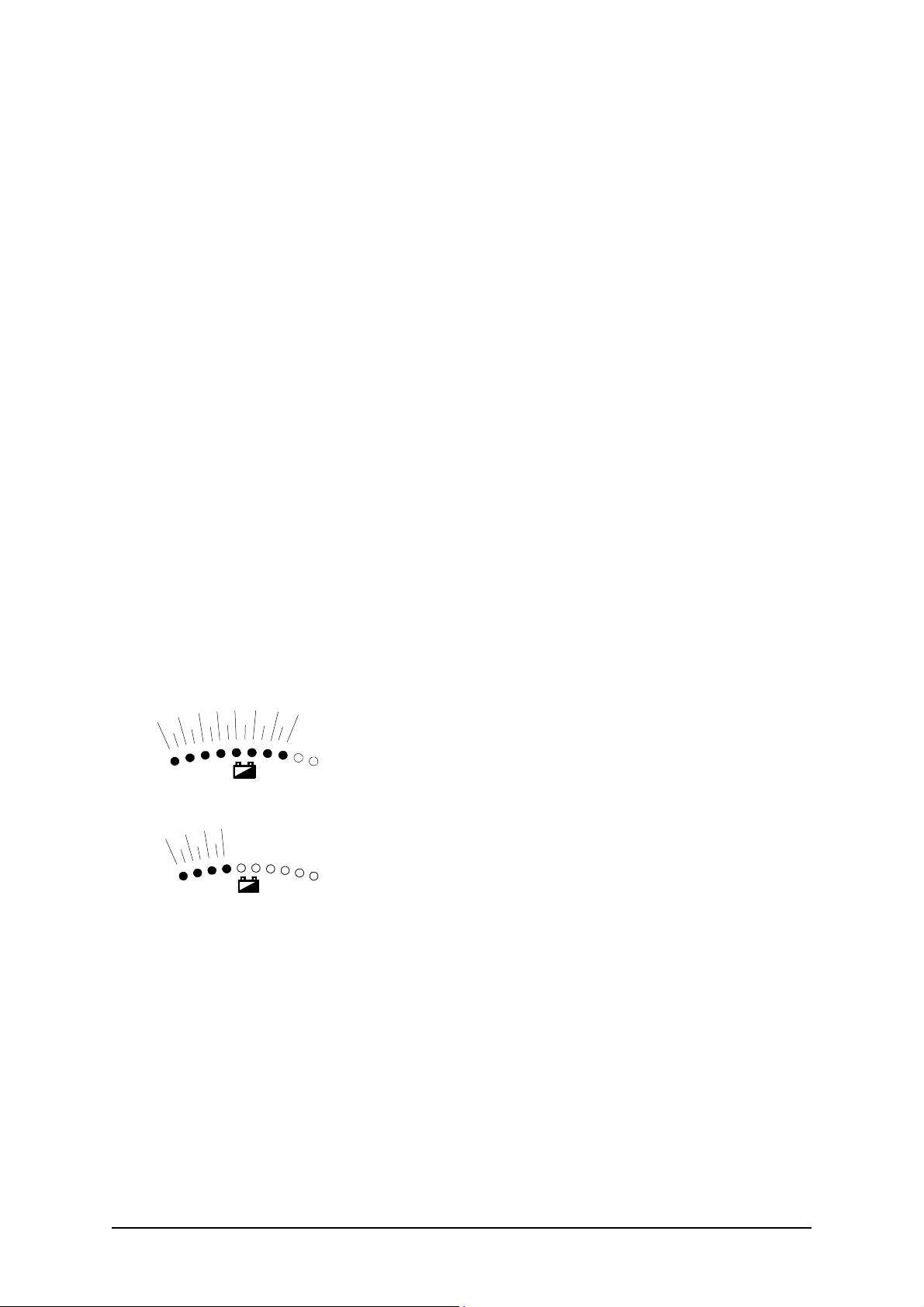
Battery Gauge
The Battery Gauge provides true, useable battery capacity information. A full
battery with at least 85 % of rated capacity, is represented by all ten LED’s lit.
Some new batteries can start with as little as 80 % capacity, developing higher
capacity in their early life (sometimes up to 110 %), before slowly
deteriorating over their rated life.
As the battery voltage drops, the number of LEDs lit reduces from right to left.
When only the red LEDs are lit, the available battery capacity is typically less
than 10 %. At this level and below, the Battery Gauge flashes at 1 Hz to alert
the user that the wheelchair is running on reserve capacity. The battery
capacity will reduce more rapidly in the reserve capacity range.
Battery Saver
The Battery Saver is a feature programmed into the DX Remote. When the
battery capacity is in the reserve range (below 21V), the wheelchair
performance is reduced. This is to preserve the life of the battery by
encouraging the user to recharge the battery before it becomes harmfully flat.
Operating the wheelchair with more than two LEDs of the Battery Gauge lit
will generally give normal wheelchair performance. This is provided that the
battery size and the PM program settings are matched to the wheelchair.
16
Batteries and Charging 7
Page 21
No. 60025, Issue 5. January 1999
Battery Condition Warnings
A battery warning is shown by the Battery Gauge flashing its LEDs, the
number of which depends on what it currently has lit.
Battery High warning condition
This condition occurs when the battery voltage exceeds 28V, as measured by
the PM.
The cause can be :
! The wheelchair is still on charge and the batteries are full or faulty.
! The batteries are overcharged.
! The wheelchair is travelling down a slope and the batteries are full or
faulty.
The wheelchair will drive during this fault condition which will reset
automatically when the battery voltage drops below 28V.
Battery Low warning condition
This condition occurs when the battery voltage drops below 23.3V, when the
joystick is in neutral.
The cause can be :
If the Battery Gauge flashes with orange or green
LEDs lit, but the cause is not due to a Battery High
warning condition, the battery or battery wiring may
be faulty.
If the Battery Gauge flashes with just the left 3 or 4
LEDs after stopping the wheelchair, the battery may
be too small for the wheelchair type, or the battery
may be old or damaged.
The wheelchair will drive during this fault condition, but the flashing will
continue until the joystick is returned to neutral again.
A Battery Low warning normally coincides with a Low Capacity warning.
7 Batteries and Charging
17
Page 22

No. 60025, Issue 5. January 1999
Low Capacity warning condition
When the calculated available battery capacity drops below 10% of full
capacity the two left most red LEDs flash.
The wheelchair will drive during this fault condition but it shows that the
battery is in the reserve capacity range and battery capacity will begin to
reduce rapidly. The Low Capacity warning will not stop until the batteries have
been recharged adequately.
18
Batteries and Charging 7
Page 23

No. 60025, Issue 5. January 1999
8 Programming
Warning !!
Incorrect or inappropriate programming of a DX System can put the wheelchair into
a dangerous state. Dynamic Controls accept no responsibility or liability for
accidents caused by incorrect programming. This Programming section, the HHP
Manual, and the Dynamic Wizard Installation Sheet/Online Help must be read and
understood before attempting to program a DX System.
Ensure that the programmed wheelchair complies with all prevailing regulatory
requirements for your country and application.
Introduction
The driving performance of the DX System is dependant on its programming.
Different features can be selected and parameters fine tuned for a particular
application, or to suit the requirements of an individual.
The DX Remote and the DX Power Module are the modules most responsible
for defining the driving performance of the DX System. Software in the DX
Remote, processes the joystick movements according to its Drive Programs,
and sends direction and speed commands to the PM.
Default Programs
The Dolphin is programmed during manufacturing with a set of factory default
settings which are incorporated into a controlled document by Dynamic. The
default settings programmed into a Dolphin will not be suitable for all DX
Systems and must be checked and reprogrammed prior to connecting with a
DX System.
The optimum settings for all programmable DX Modules are determined by the
wheelchair manufacturer (OEM). If more than one type of wheelchair is to be
used by the customer, each wheelchair type may have its own set of optimum
settings.
Warning : If a wheelchair is programmed with settings other than default,
under some very rare fault conditions default settings could be automatically
restored, thereby changing driving characteristics. This in turn could lead to a
chair moving in a direction or speed that is not intended. Programmers should
consider this risk when programming settings other than default.
8 Programming
19
Page 24

No. 60025, Issue 5. January 1999
Auto Download
The DX System has a feature called Auto Download. It is designed to
minimise the programming requirements associated with Module servicing by
down loading the correct programming to a replacement DX Module.
A DX Module with a flashing System Status LED is considered faulty and,
when serviced, is replaced by a new one. The replacement module is likely to
be programmed differently to the one that it replaces, which could leave the
wheelchair in a dangerous state. The DX System automatically detects that a
DX Module swap has occurred, and the programmed data from the old module
is transferred to the replacement module.
Auto Download is achieved by the DX Remote containing both its own
programming and also a backup copy of the programmed data for all other DX
Modules. When a module swap is detected, or a checksum error found in a
module, the DX Remote automatically down loads its backup copy to the
module. The Auto Down load occurs immediately on power up after the
Module has been replaced. This applies to all DX Modules except a DX
Remote.
Warning : When a Dolphin is replaced it will perform an Auto Down load
to all DX Modules. This may result in incorrect and dangerous programming
for a particular wheelchair system if the wheelchair program installed in the
Dolphin is not suitable for that wheelchair system.
Do not attempt to drive or test the DX System before the correct and suitable
wheelchair program has been installed in the Dolphin using the Wizard.
The Dolphin can be programmed with the Wizard using a ‘dummy’ DX
System and / or a 24V power supply, or on the wheelchair provided driving is
prevented e.g. by disengaging the drive wheels.
After replacing any DX Module, turn the DX System off, then on again, to
initiate the Auto Down load of the DX Remote backup data. When a Auto
Down load has occurred, but the system needs to be cycled on and off, a
Module Fault (Flash Code 1) is displayed on the DX Remote’s System Status
LED and also the Status LED of the offending module. When the System if
turned off then on again, the fault is cleared and the Auto Down load is
correctly terminated.
20
Programming 8
Page 25

No. 60025, Issue 5. January 1999
Programming Tools
Two programming tools are available, the Dynamic Wizard and the HHP.
Dynamic Wizard
The Wizard is a PC based tool suited to programming production runs of
identical wheelchairs or modules, or individual highly customised wheelchairs.
The Wizard is available in several versions :
OEM Generally used by the wheelchair manufacturer. Able to
program a wide range of parameters.
DEALER Similar in function to above, but with a reduced range of
programmable options. This ensures that options that the
manufacturer wishes to keep control of cannot be
disturbed. Parameters that may cause hazards or require
special expertise to be set are not available to adjust.
ENHANCED As above but with the ability to edit parameters that relate
DEALER directly to wheelchair accessories (e.g. actuators).
FACTORY Can only replace Standard or Custom Wheelchair
Programs. No editing or diagnostics available.
Warning : The Wizard is a very powerful tool and as such requires well
trained operators and a disciplined approach to usage and distribution.
It is up to the wheelchair manufacturer to determine whether they will allow
distribution of the Wizard to dealers. Refer to the Wizard Documentation for
further details.
DXBUS +DXBUS -
A Dolphin can be programmed with the
Wizard using a 24V power supply and an
optional PM. If the Dolphin is connected
directly to the 24V power supply, then a
DXBUS Cable can have one end modified to
connect to the power supply.
Dolphin DXBUS Pins
8 Programming
21
Page 26

No. 60025, Issue 5. January 1999
HHP
The DX Hand Held Programmer (HHP) is the normal programming tool used
by dealers, allowing easy adjustment of all commonly adjusted Drive Program
parameters.
Warning : The DX HHP is for use only by wheelchair manufacturers, their
authorised dealers and support personnel. It is not intended for use by the
wheelchair user.
The DX HHP Manual should be read and understood before attempting to use
it.
Wizard High Volume Programming.
Programming in the factory environment is normally done using the Wizard.
With the Wizard’s Create a new Chair Program option, you can set up the
standard parameters for the Dolphin and any other modules used for a
particular wheelchair. This Chair Program is then saved to disk under a name
such as "SuperChair, Deluxe, with lights" and can be down-loaded to a
Dolphin at the push of a button.
Example
Modify/Edit the "SuperChair, Deluxe, with Lights” Chair Program as
follows.
1. Enter the Wizard’s Main Menu screen as described in the Wizard
Installation Sheet.
2. Use the keyboard or the mouse, to select the File, Open menu option.
3. Select the “SuperChair, Deluxe” program from the dialog box.
4. Select the ‘Edit Module Parameters’ menu option.
6. Select ‘UCM Remote’ or the required group of parameters.
7. Scroll through the list of Dolphin parameters and adjust as necessary.
22
Programming 8
Page 27

No. 60025, Issue 5. January 1999
8. Press «Enter» to accept the changes, or «Esc» to exit without saving. Select
the File, Save menu option. These values will then be part of the Standard
Chair Program for the “SuperChair, Deluxe”
Down load the “SuperChair, Deluxe” to a Dolphin as follows.
1. Connect the Wizard serial communications cable to the Dolphin
programmer socket and return to the main menu of the Wizard.
2. Use the keyboard or the mouse to select the File, Open menu option.
3. Select the “SuperChair, Deluxe” program from the dialog box.
4. Select the ‘Program Wheelchair’ option.
5. Choose if the Chair Program is to be down-loaded to the ‘Total System’ (to
program a fully built up chair system) or just the ‘UCM Remote’ (to preprogram the Dolphin only).
6. Press «Enter» to write the Chair Program data.
7. Disconnect the Dolphin and repeat for as many Dolphins, or DX Systems,
as required, by repeating steps 4 through 7.
8 Programming
23
Page 28

No. 60025, Issue 5. January 1999
DX Dolphin Wizard Programming
The Wizard accesses a set of parameters that are programmed to define the
configuration desired by a wheelchair manufacturer.
Some parameters can be both read and written to (edited) by an OEM and a
Dealer. Other parameters can only be read but not edited. Some parameters
available to an OEM are not displayed by a dealer.
The DX System, with the Dolphin, supports up to five user selectable Drive
Programs. The Drive Programs govern the performance of the wheelchair, as
suitable for different environmental and user conditions. Drive Programs are
also adjustable with the HHP.
Remaining parameters are related to other system functions and DX Modules
which may, or may not, be included in your DX System. Parameters that may
be accessed by the HHP are marked with an asterisk (*).
Drive Program Parameters
The five Drive Programs (or Profiles) can be set up as, for example, an Indoors
program, an Outdoors program or a Sports program. These settings are
originally factory set to the values defined in the Chair Program used by the
Wizard during the down-loading process.
The values of the Drive Programs can be altered for a particular wheelchair
user using an HHP if necessary (except Damping Point and Sleep Timeout).
Note: As all program settings are stored in the Dolphin, replacement of the
Dolphin in the DX System may result in a change in Drive Program values that
may be substantially and dangerously different from those of the Dolphin it
replaced. The Wizard may be used to up-load and save the 'old' system settings
for later reprogramming of the replacement Dolphin.
Program (Profile) 6 is a special program that is automatically selected when an
Attendant Control Unit (ACU) is connected and in the Attendant mode. Note
that Program 6 is not programmable using the HHP on standard Dolphins.
When the ACU is disconnected, or it returns to the 'User Mode', the wheelchair
automatically reverts to the Program that was selected prior the ACU
becoming active (see ACU User Manual for more details).
24
Programming 8
Page 29

No. 60025, Issue 5. January 1999
The Wizard can be used to restrict the minimum and maximum limits for Drive
Program parameters adjustable with an HHP.
Max Forward Speed * Range : 10 - 100% Default : 100
OEM Access: Read / Write
Dealer Access: Read / Write
Sets the maximum speed obtainable for maximum forward joystick
deflection.
Forward Acceleration * Range : 10 - 70% Default : 40
OEM Access: Read / Write
Dealer Access: Read / Write
Sets the maximum output (linear) acceleration rate for large joystick
forward deflections, where 70% provides the quickest response.
Warning : Setting the Acceleration / Deceleration too low or too high can
result in an unsafe wheelchair. Test thoroughly after programming to ensure
that the wheelchair complies with regulatory requirements such as ISO7176
7176 and the GMD-TND Homologation Directive R04 for maximum allowable
braking distance.
Forward Deceleration * Range : 15 - 100% Default : 70
OEM Access: Read / Write
Dealer Access: Read / Write
Sets the maximum braking effect (linear deceleration) for large joystick
deflection back towards neutral, where 100% provides maximum braking
effect.
Max Reverse Speed * Range : 10 - 100% Default : 70
OEM Access: Read / Write
Dealer Access: Read / Write
Sets the maximum speed obtainable for maximum reverse joystick
deflection.
8 Programming
25
Page 30

No. 60025, Issue 5. January 1999
Reverse Acceleration * Range : 10 - 70% Default : 40
OEM Access: Read / Write
Dealer Access: Read / Write
Sets the maximum output (linear) acceleration rate for large joystick
backward deflections, where 70% provides the quickest response.
Reverse Deceleration * Range : 15 - 100% Default : 70
OEM Access: Read / Write
Dealer Access: Read / Write
Sets the maximum braking effect (linear deceleration) for large joystick
deflection back towards neutral, where 100% provides maximum braking
effect.
Max Turning Speed * Range : 10 - 100% Default : 50
OEM Access: Read / Write
Dealer Access: Read / Write
Sets the maximum turning speed obtainable for maximum joystick
deflection left or right.
Turning Acceleration * Range : 10 - 70% Default : 40
OEM Access: Read / Write
Dealer Access: Read / Write
Sets the maximum output (linear) acceleration rate for large joystick left
and right deflections, where 70% provides the quickest response.
Turning Deceleration * Range : 15 - 100% Default : 70
OEM Access: Read / Write
Dealer Access: Read / Write
Sets the maximum braking effect (linear deceleration) for large joystick
deflection back towards neutral, where 100% provides maximum braking
effect.
26
Programming 8
Page 31

No. 60025, Issue 5. January 1999
Damping Point * Range : 10 - 100% Default : 40
OEM Access: Read / Write
Dealer Access: Read / Write
The damping point defines the speed error size (of output speed verses
joystick demand speed) using progressive error reduction (ie acceleration
/ deceleration). Speed errors exceeding this value will be limited to the
programme maximum linear acceleration or deceleration rate. In other
words it sets the 'compromise' ratio between joystick directness /
responsiveness and chair controllability. Note: for most applications the
default value of 40% should not require adjusting. Achieving the desired
response is done by setting the appropriate acceleration / deceleration
values.
Warning : An unsuitably high or low value can make the wheelchair
unstable.
Joystick Source * State : Local / Remote Default : Local
OEM Access: Read / Write
Dealer Access: Read / Write
Selects whether the Drive Program will use the Dolphin's built in joystick
or an external RJM based input control device.
Reverse J/S - Fwd/Rev State : Normal / Reverse Default : Normal
OEM Access: Read / Write
Dealer Access: Read only
Reverses the direction of the Dolphin’s inbuilt joystick, This can be set
for each profile.
If set to ‘Normal’, forward and reverse joystick deflection causes forward
and reverse motion respectively.
If set to ‘Reverse’, forward and reverse joystick deflection causes the
opposite effect. Used if the Dolphin was to be mounted in any other than
standard orientation in order to maintain joystick sense.
8 Programming
27
Page 32

No. 60025, Issue 5. January 1999
Sleep Timeout Range : 1 - 255 min. (off) Default : 255 min (off)
OEM Access: Read / Write
Dealer Access: Read / Write
Inactivity timeout. The DX system goes to sleep after 'x' minutes of
inactivity, if enabled.
Keypad and Speed Pot Parameters
Max Profile Number Range: 1 - 5 Default: 5
OEM Access: Read / Write
Dealer Access: Read only
Sets the number of Profiles (Drive Programs) available for selection by
the user of the Dolphin. The Dolphin supports up to 5 user programs
(profiles).
Wrap Profiles State: yes / no Default: yes
OEM Access: Read / Write
Dealer Access: Read only
Allows Profile 5 to wrap around to Profile 1 (and vice-versa).
Change Prof Driving State: yes / no Default: no
OEM Access: Read / Write
Dealer Access: Read only
If set to ‘no’, the Drive Program can only be changed while the
wheelchair is stopped. If set to ‘yes’, the Drive program can be changed
while driving.
Warning : Care should be taken if set to ‘yes’ if adjacent Drive
Programs have markedly different settings (this includes the wrap-around
between Prog 1 and Prog 5).
We recommend you do not set this parameter to ‘yes’ if the DX System
contains an RJM based input device, as this would cause the wheelchair
to come to a sudden halt when changing to an RJM Drive Program, or
visa versa.
28
Programming 8
Page 33

No. 60025, Issue 5. January 1999
Allow Non Driv Prof State: yes / no Default: no
OEM Access: Read / Write
Dealer Access: Not available
If set to ‘yes’, Drive Program 0 is enabled and is displayed between
Drive Profile 5 and Drive Profile 1.
Lock Enable State: yes / no Default: yes
OEM Access: Read only
Dealer Access: Read only
Enables the Dolphin's magnetic key operated lock function.
Speed Pot Scalar Range: 20 - 100% Default: 100
OEM Access: Read / Write
Dealer Access: Read only
The Dolphin does not have a speed potentiometer, do not change default.
Sets the maximum forward and reverse speed scalar when speed pot is set
at minimum.
Sleep Mode Enable State: disable / enable Default: disable
OEM Access: Read / Write
Dealer Access: Read / Write
Set to 'Enable' if Sleep Mode is required. System goes to sleep (partial
power down) after [sleep timeout] minutes of inactivity. The system can
be woken up by activating the last selected device or any switch on the
Dolphin.
8 Programming
29
Page 34

No. 60025, Issue 5. January 1999
Joystick Parameters
Neutral Maximum Range: 10 - 49 Default: 10
OEM Access: Read / Write
Dealer Access: Read / Write
Determines the neutral window size. Affects all joysticks used in the
system. Adjust only in special cases.
Neutral to PB Delay Range: 20 - 5000 msec Default: 100
OEM Access: Read / Write
Dealer Access: Read only
The delay between zero output speed and de-energising the Park Brake.
It is dependant on the particular Park Brake mechanics and motor
characteristics. It is set so as to minimise the jerk or roll back when
parking on a slope. The jerk is also influenced by the Load Compensation
setting in the Power Module.
Reverse UCM Joystick State: normal / reverse Default: normal
OEM Access: Read / Write
Dealer Access: Read only
Reverses the direction (left / right) of the Dolphin’s inbuilt joystick.
If set to ‘Normal’, left and right joystick deflection causes a left and right
turn, respectively.
If set to ‘Reverse’, left and right joystick deflection produces the opposite
effect. Forward and reverse are not affected. Used if the Dolphin is
mounted in an other than standard orientation in order to maintain normal
joystick sense.
UCM Dual Decode State: single / dual Default: dual
OEM Access: Read only
Dealer Access: Not available
Set to 'dual' for six wire joysticks with mirror signals. Normally set to
'dual' for safety requirements (View only, not adjustable by OEM).
30
Programming 8
Page 35

No. 60025, Issue 5. January 1999
ACU Enable State: yes / no Default: yes
OEM Access: Read / Write
Dealer Access: Read / Write
Must be set to ‘yes’ for Attendant Control Unit (ACU) operation. The
Dolphin will automatically detect the presence of an ACU when the DX
System is turned on.
Reverse ACU Joystick State: normal / reverse Default: normal
OEM Access: Read / Write
Dealer Access: Read only
Reverses the direction (left / right) of the ACU joystick.
If set to ‘No’, left and right joystick deflection causes a left and right turn,
respectively.
If set to ‘Yes’, left and right joystick deflection produces the opposite
effect. Forward and reverse are not affected. Used if the ACU is mounted
in an other than standard orientation in order to maintain normal joystick
sense.
ACU Dual Decode State: single / dual Default: dual
OEM Access: Read only
Dealer Access: Not available
Set to ‘dual’ if the ACU is connected and has a six wire joystick with
mirror signals. Normally set to ‘dual’ for safety requirements. (View only,
not adjustable by OEM).
RJM Enable State: yes / no Default: yes
OEM Access: Read / Write
Dealer Access: Read / Write
Must be set to ‘yes’ for Remote Joystick Module (RJM) operation. The
Dolphin will automatically detect the presence of an RJM when the DX
System is turned on.
8 Programming
31
Page 36

No. 60025, Issue 5. January 1999
Reverse RJM Joystick State: normal / reverse Default: normal
OEM Access: Read / Write
Dealer Access: Read / Write
Reverses the direction (left / right) of the RJM joystick.
If set to 'Norm', left and right joystick deflection causes a left and right
turn, respectively
If set to ‘Yes’, left and right joystick deflection produces the opposite
effect. Forward and reverse are not affected. Used if the RJM is mounted
in an other than standard orientation in order to maintain normal joystick
sense.
RJM Dual Decode State: single / dual Default: dual
OEM Access: Read only
Dealer Access: Not available
Set to ‘dual’ if the RJM is connected and has a six wire joystick with
mirror signals. Normally set to ‘dual’ for safety requirements. (View only,
not adjustable by OEM).
Actuator Parameters
Refer to the Installation Manual for the DX Module driving the actuators,
e.g. TAM, CLAM, ARC5.
CLAM Enable * State: yes / no Default: no
OEM Access: Read / Write
Dealer Access: Read / Write
Must be set to ‘yes’ for CLAM or TAM operation.
CLAM is critical State: yes / no Default: no
OEM Access: Read / Write
Dealer Access: Read only
If set to ‘yes’, a CLAM or TAM must be present in the system and
operating normally. The loss or lack of communications between the
CLAM (or TAM) and the Dolphin will cause the wheelchair to stop, and
a Flash Code 1 to be displayed by the Remote.
32
Programming 8
Page 37

No. 60025, Issue 5. January 1999
If set to ‘no’, the wheelchair will drive normally with no CLAM (or
TAM) attached. Providing that all CLAM (or TAM) parameters have
been programmed, this is a useful factory setting. It allows a CLAM (or
TAM) to be added later to wheelchair systems that do not have one fitted,
without the HHP or Wizard.
CLAM Slowdown Range: 0 - 100% Default: 20
OEM Access: Read / Write
Dealer Access: Read only
Set to a required percentage of maximum wheelchair speed allowed when
the slow input is active. For this facility to be used, the hardware of the
wheelchair must be arranged as described in the Slow / Stop section in
the Installation Manual of the DX Module driving the actuators, e.g.
CLAM or TAM.
Actuator 1 Enable State: yes / no Default: no
OEM Access: Read / Write
Dealer Access: Read only
If set to ‘Yes’, Actuator 1 is enabled and can be selected by pressing the
Actuator 1 select switch on the Dolphin or ARC (Actuator Remote
Control) type module.
If set to ‘no’, there will be no response to the Dolphin Actuator switch.
Actuator buttons can be disabled if there are less actuators fitted to the
wheelchair than the number of actuator switches on the Remote.
Actuator 2 Enable State: yes / no Default: no
to
Actuator 5 Enable
OEM Access: Read / Write
Dealer Access: Read only
As described for Actuator 1 Enable. Refer to the Installation Manual for
the DX Module driving the actuators, e.g. TAM, CLAM, ARC5.
8 Programming
33
Page 38

No. 60025, Issue 5. January 1999
Actuator 1 I Limit Range: 3 - 12 amps Default: 6
to
Actuator 5 I Limit
OEM Access: Read / Write
Dealer Access: Read only
Sets the current trip point for each actuator between the allowable range
of 3 - 12 Amps. Refer to the Installation Manual of the Actuator Module
for details.
Actuator Timeout Range: 1 - 120 sec. Default: 30
OEM Access: Read / Write
Dealer Access: Read only
Sets the maximum time a wheelchair user can continuously operate any
actuator.
Actr Open Circ Test State: yes / no Default: no
OEM Access: Read / Write
Dealer Access: Not available
When set to ‘Yes’, an open circuit at the actuator output pins of the
Actuator Module (e.g. TAM or CLAM), will cause a Flash Code 2 to be
displayed (see Diagnostics section). The wheelchair will still drive.
ARC Enable State: yes / no Default: no
OEM Access: Read / Write
Dealer Access: Read / Write
Must be set to ‘yes’ for Actuator Remote Control (ARC) operation.
Set to ‘no’ for control of actuators by the switches on the Dolphin and
joystick.
Joystick Actuator State: yes / no Default: yes
OEM Access: Read / Write
Dealer Access: Read / Write
Set to ‘no’ if switch operation of actuators is required. This is not
recommended since the Dolphin has only one switch per actuator.
34
Programming 8
Page 39

No. 60025, Issue 5. January 1999
Set to ‘yes’ if joystick operation of actuators is required. The Actuator
Select switch will now select the actuator, if fitted, but will not cause it
to operate. If the wheelchair is driving when an actuator is selected, it will
stop driving.
Num Actuator Button State: one / two Default: two
OEM Access: Read / Write
Dealer Access: Read / Write
When set to ‘one’, pressing an Actuator Select switch, or moving the
joystick forward, will toggle between the actuator up / extend and
actuator down / retract.
Can only be set to ‘two’ for the Dolphin if the Joystick Actuator
parameter is set to ‘yes’. In this case, the joystick forward is used for
actuator up / extend, and joystick down for actuator down / retract.
Actr While Drive State: yes / no Default: no
OEM Access: Read / Write
Dealer Access: Read only
If set to ‘No’, the wheelchair will not drive while an actuator is being
operated. If the wheelchair is driving, the actuator command will be
ignored until the joystick returns to neutral.
If set to ‘yes’ and the Joystick Actuator
parameter is set to 'Yes', pressing the actuator
button will stop the wheelchair from driving and
select the actuator. The joystick can not be used
to operate the actuator until it has returned to
within the 50% window around neutral.
If the Joystick Actuator parameter is set to 'No',
actuators can be operated irrespective of the
driving state of the wheelchair.
8 Programming
35
Page 40

No. 60025, Issue 5. January 1999
Lighting Parameters
Lighting Mod Enable * State: yes / no Default: no
OEM Access: Read / Write
Dealer Access: Read / Write
Set to ‘yes’ for Lighting Module (LM) operation, ‘no’ if Combined
Lighting Actuator (CLAM) based lights are used.
CLAM Lighting Enable * State: yes / no Default: no
OEM Access: Read / Write
Dealer Access: Read / Write
Set to ‘yes’ for CLAM operation, ‘no’ in all other cases.
Side Lights Enable State: yes / no Default: yes
OEM Access: Read / Write
Dealer Access: Read only
If set to ‘yes’, Side Lights, if fitted, can be operated by the Dolphin.
If set to ‘no’, there will be no response to the Dolphin Light switch.
Indicators Enable State: yes / no Default: yes
OEM Access: Read / Write
Dealer Access: Read only
If set to ‘yes’, Indicators, if fitted, can be operated by the Dolphin.
If set to ‘no’, there will be no response to the Dolphin Indicator switches.
Hazard Enable State: yes / no Default: yes
OEM Access: Read / Write
Dealer Access: Read only
If set to ‘yes’, Hazard Lights, if fitted, can be operated by the Dolphin.
If set to ‘no’, there will be no response to the Dolphin Hazard Light
switch.
36
Programming 8
Page 41

No. 60025, Issue 5. January 1999
DX Dolphin HHP Programming
Warnings: Do not plug the HHP in while the vehicle is in motion. Plug in
the HHP while the DX System is turned on. A setting is saved once the NEXT
button is pressed. If the DX System is turned off during programming, the
current parameter being modified will not be saved and DX System will retain
the previous setting.
Initial Operation
1. Turn on the DX System and plug the HHP into the Programmer Socket on
the Dolphin. The initial screen appears for two seconds.
DX HHP V1.x
If a fault has occurred, the fault screen appears.
SYSTEM FAULT
5
L parkbrake
EXIT
The number and message displayed represents the Flash Code. See the
Diagnostics section for the list of faults that can be displayed.
Press EXIT to return to the main menu.
2. Then the main menu screen reads :
* * MAIN MENU * *
View or edit?
Program : 1 ?
NEXT YES
Pressing NEXT cycles through the Main Menu options. These are the
Drive Programs and Technician Mode enable / disable.
8 Programming
37
Page 42

No. 60025, Issue 5. January 1999
Test Driving and Saving Changes
Changes can be test driven before being permanently saved as the DX System
can be driven with the HHP plugged in. Even if the HHP is disconnected, the
changes will remain current until the DX Remote is turned off. Once turned
off, the settings will return to their original values.
Changes are saved when the NEXT button on the HHP is pressed. If the DX
Remote is turned off before the HHP is returned to the main menu, all changes
to the current parameter are lost.
To View / Adjust Drive Programs
Pressing EXIT at any point during the procedure will return you to the main
menu.
1. Press NEXT in the main menu until the appropriate Drive Program is
shown.
* * MAIN MENU * *
View or edit
Program : 1 ?
NEXT YES
2. Press YES to edit Drive Program.
3. The screen now reads :
TUNE PROG 1 RESPONSE
Max forward speed
25%
EXIT NEXT UP DOWN
Press NEXT to step through the adjustable parameters.
These are : Max. Forward Speed
Forward Acceleration
Forward Deceleration
Max. Reverse Speed
Reverse Acceleration
Reverse Deceleration
Max. Turning Speed
Turning Acceleration
Turning Deceleration
38
Programming 8
Page 43

Damping Point
Joystick Source
Reverse Joystick - Fwd/Rev
Press UP or DOWN to adjust the value (excluding Joystick Source).
To Adjust Joystick Source
The Joystick Source screen reads :
EXIT NEXT SWAP
Pressing ‘SWAP’ toggles the parameter between :
‘Remote’ if an RJM based input device is fitted, and ‘Local’ if the
joystick on the Dolphin is to be used.
No. 60025, Issue 5. January 1999
TUNE PROG 1 RESPONSE
Joystick Source
Local
This setting does not affect the ACU profile.
Reverse Joystick - Forward / Reverse
The Joystick Reverse screen reads :
TUNE PROG 1 RESPONSE
Joystick reverse
Normal
NEXT SWAP
2. Pressing ‘SWAP’ toggles the parameter between ‘Normal’ and ‘Reverse’.
This parameter reverses the forward / reverse direction of the controlling
joystick.
If set to 'Normal', forward and reverse joystick deflection causes forward
and reverse motion respectively.
If set to ‘Reverse’,forward and reverse joystick deflection causes the
opposite effect. Used if the Dolphin was to be mounted in any other than
standard orientation in order to maintain joystick sense.
8 Programming
39
Page 44

No. 60025, Issue 5. January 1999
To Enable Technician Mode
1. In the main menu, press NEXT until the Technician Mode screen appears:
* * MAIN MENU * *
Technician Mode
disabled. Enable ?
NEXT YES
Pressing YES toggles this screen between Technician Mode Enabled and
Technician Mode Disabled. If disabled, press YES to enable.
2. Press YES and a password screen will appear.
Technician Mode
Enter Password
0 0 0
EXIT D1 D2 D3
3. Press the D1, D2 and D3 buttons to cycle each digit through to the correct
password. When the password reads correctly, press the EXIT button.
4. The screen now reads :
* * MAIN MENU * *
Technician Mode
enabled. Disable ?
ì
NEXT YES
Joystick Calibration
1. Enable the Technician Mode
2. Press NEXT in the main menu until the screen reads :
* * MAIN MENU * *
View or edit Remote
Module ? (Tech Only)
NEXT YES
Press YES.
40
Programming 8
Page 45

No. 60025, Issue 5. January 1999
3. The display reads:
JOYSTICK CALIBRATION
EXIT NEXT BEGIN
Pressing EXIT at any point during the calibration procedure will return
you to screen .
ì
6. Press BEGIN.
JOYSTICK CALIBRATION
Rotate J/S
-> Neutral -> END
EXIT END
7. Move the joystick around the outer physical extremities of the restrictor
plate. Ensure that all corners are pressed into.
Return the joystick to neutral.
8. Press END to end the sequence and return to the main menu.
The calibration is saved.
Combined Lighting Actuator Module (CLAM) Enable
1. Enable the Technician Mode
2. Press NEXT in the main menu until the screen reads :
* * MAIN MENU * *
View or edit Remote
Module ? (Tech Only)
NEXT YES
Press YES.
3. The display reads:
8 Programming
CLAM
disabled. Enable ?
EXIT NEXT YES
41
Page 46

No. 60025, Issue 5. January 1999
Pressing YES toggles between CLAM enabled and CLAM disabled.
Setting this parameter to ‘Enabled’ allows the CLAM or TAM to be used
in the DX System.
Pressing EXIT will return you to screen .
ì
Lighting Module (LM) Enable
1. Enable the Technician Mode
2. Press NEXT in the main menu until the screen reads :
* * MAIN MENU * *
View or edit Remote
Module ? (Tech Only)
NEXT YES
Press YES.
3. The display reads:
LM
disabled. Enable ?
EXIT NEXT YES
Pressing YES toggles between LM enabled and LM disabled. Setting this
parameter to ‘Enabled’ allows the LM to be used in the DX System.
Pressing EXIT will return you to screen .
ì
42
Programming 8
Page 47

No. 60025, Issue 5. January 1999
9 Diagnostics and Fault Finding
DX Dolphin diagnostics can be examined from two platforms : from the Flash
Codes signalled with the System Status LED on the Dolphin (and on the HHP);
and from the Wizard which can provide more detailed information about the
fault.
Flash Code
Any fault condition on the DX system will cause the Dolphin’s System Status
LED to flash. Flashing occurs in bursts of flashes separated by a two second
pause. The number of flashes in each burst is referred to as the Flash Code and
indicates the nature of the fault. The title of the Flash Code fault is also
displayed by the HHP if connected to the faulty wheelchair.
Faults that affect the safety of the chair will cause the chair to stop while less
critical ones will be indicated but allow the chair to continue driving. Some
faults will automatically clear when the fault condition is removed, in which
case the System Status LED will become steady and the wheelchair may be
driven normally. Other faults are latched and must be cleared by turning the
DX System off, waiting for two seconds, turning it back on again.
DX System
Status LED
Flash Code
1
Likely Cause of Condition and Possible Action
DX Module Fault (see Limp Mode below)
Cause: An Auto Download has occurred.
Action < Turn the Dolphin off then on again.
Cause: The Dolphin is not correctly programmed.
Action < Try reprogramming the Dolphin.
Cause: Connection between DX Modules may be faulty,
or there may be an internal fault in a Module.
Action < Check DXBUS connections and replace where
necessary.
< If the Status LED on another Module is
flashing, replace the Module.
< An expected module may not be present (e.g.
the DX Lighting Module).
9 Diagnostics and Fault Finding
43
Page 48

No. 60025, Issue 5. January 1999
DX System
Status LED
Flash Code
2
3
Likely Cause of Condition and Possible Action
DX Accessory Fault
Cause: There is a fault in an accessory device attached to
a DX Module (excluding the PM). Examples of
faults in accessory devices may be : the clutch is,
or has been, disengaged; a light bulb is short or
open circuit; an actuator terminal is shorted to
Battery +.
Action < Check all accessory devices connected to your
DX System.
Left (M1) Motor Fault
Cause: The connection from the PM left (M1) connector
to its associated motor, or the motor itself, is
defective. The connection is either open or short
circuit.
Action < Disconnect the left motor plug and check
continuity between the motor pins on M1.
4
Right (M2) Motor Fault
Cause: The connection from the PM right (M2) connector
to its associated motor, or the motor itself, is
defective. The connection is either open or short
circuit.
Action < Disconnect the right motor plug and check
continuity between the motor pins on M2.
5
Left (M1) Park Brake Fault
Cause: The M1 plug connection to its associated Park
brake is either open or short circuit.
Action < Disconnect the M1 plug and check continuity
between the two Positronic park brake pins.
6
Right (M2) Park Brake Fault
Cause: The M2. plug connection to its associated Park
brake is either open or short circuit.
Action < Disconnect the M2. plug and check continuity
between the two Positronic park brake pins.
44
Diagnostics and Fault Finding 9
Page 49

No. 60025, Issue 5. January 1999
DX System
Status LED
Flash Code
7
8
Likely Cause of Condition and Possible Action
Low Battery Fault
Cause: The battery charge is not sufficient to allow safe
driving. It has fallen below 17V
Action < Check battery connection and terminals. The
battery voltage should be similar when the
battery is on charge, and when it isn’t.
< Check that fuses have not blown, or circuit
breakers tripped.
< Replace battery if worn out or if capacity is
insufficient for the user’s needs.
Note: The wheelchair will behave sluggishly and the
Battery Gauge will flash indicating low battery voltage
prior to the display of this fault.
Overvoltage Fault
Cause: The battery voltage has exceeded 32V.
Action < If this fault occurs during battery charging, the
battery charger is defective or incorrectly
adjusted.
< Check the battery chargers open circuit voltage
is in accordance with the battery manufacturers
limits, and is less than 32V.
Cause: The battery connector is making intermittent
contact when the wheelchair is stopped, or
travelling down a slope.
Action < Check that the battery wiring and terminating is
secure.
9
CANL Fault (see Limp Mode below)
Cause: 1. An invalid voltage has been detected on the
Action < Check the continuity of the DXBUS cable.
9 Diagnostics and Fault Finding
DXBUS CANL line.
2. Communication is not possible using the CANL
wire.
< Check for shorts between DXBUS pins. An
open or short circuit on another DX Module
can cause this fault.
45
Page 50

No. 60025, Issue 5. January 1999
DX System
Status LED
Flash Code
10
Likely Cause of Condition and Possible Action
CANH Fault (see Limp Mode below)
Cause: 1. An invalid voltage has been detected on the
DXBUS CANH line.
2. Communication is not possible using the
CANH wire, or the CANH and CANL wires
are shorted together.
3. Hazard lights were turned on when the DX
System was turned on.
4. The CANH is used to generate a Kill signal by
any DX Module which detects an unsafe
condition, or by an external device such as an
emergency stop switch.
The CANH wire is pulled to either Battery + or
Battery - and causes the DX System to shut
down.
Action < Check the continuity of the DXBUS cable.
< Check for shorts between DXBUS pins. An
open or short circuit on another DX Module
can cause this fault.
< If the Hazard Lights were already switched on
when the DX System was turned on, Flash
Code 10 and Limp Mode (slow driving) may
result.
To clear this fault, turn the Hazard Lights off,
then turn the DX System off then on again.
< If generated by a Kill signal, the cause of the
fault is severe.
46
11
Stall Timeout Fault
Cause: The motor current has been at, or close to, current
limit for longer than the Stall Timeout parameter
value.
Action < Turn the DX System off then on again.
Diagnostics and Fault Finding 9
Page 51

No. 60025, Issue 5. January 1999
DX System
Status LED
Flash Code
12
Limp Mode
Likely Cause of Condition and Possible Action
Module Mismatch
Cause: There is a compatibility problem between DX
Modules in the System. The wheelchair will be
disabled.
Action < Consult your Dynamic Service Centre.
Cause: The data held by the Dolphin for another DX
Module is corrupt or incompatible with that
module.
Action < Reprogramming the wheelchair system may
correct this problem.
If the DX System detects some faults, it will revert to Limp Mode. This is a
reduced speed mode which recognises problems, but allows the wheelchair
user to limp home, where the problem can be assessed.
9 Diagnostics and Fault Finding
47
Page 52

No. 60025, Issue 5. January 1999
Wizard Diagnostics
The Programming Configuration Diagnostic (known as the Wizard) tool is used
to provide diagnostics for the Dolphin.
To View Diagnostics
1. Enter the Wizard’s Main Menu screen as described in the Wizard
Installation Sheet / Online Help.
2. Select the ‘Diagnostics’ menu.
The menu displays the following options:
Status Report
Print Status Report
Chair Log
Print Chair Log
Erase Chair Log
Print Chair Log prints the Status Report followed by the Chair Log. These
reports should be sent along with a faulty controller to a Service Centre.
contact a Dynamic Sales and Service Centre (refer to section 14).
Status Report
The Status report gives you the current status of the wheelchair, including
faults and other warning conditions currently active. Pressing «?» Or selecting
‘Info’ will display further information about the condition. Some conditions in
the Status Report are not caused by actual faults, but are only temporary
conditions e.g. a motor lead was not connected when the DX System was
turned on and driving was attempted, producing a Motor Fault.
To View Status Report
1. Perform steps 1. and 2. above.
2. Select ‘Status Report’.
3. From the ‘Modules Attached’ menu, select ‘UCM Remote’.
48
Diagnostics and Fault Finding 9
Page 53

No. 60025, Issue 5. January 1999
Chair Log
The Chair Log displays all faults and warning conditions recorded for the
wheelchair since the Chair Log was last erased. Some conditions logged in the
Fault History are not caused by actual faults, but are only temporary conditions
e.g. a motor lead was not connected when the DX System was turned on and
driving was attempted, producing a Motor Fault. It is recommended to erase
the Chair Log once the system is fully functional as only the previous 15 fault
conditions are recorded.
To View Chair Log
1. Enter the Wizard’s Main Menu screen as described in the Wizard
Installation Sheet / Online Help.
2. Select the ‘Diagnostics’ menu.
3. Select ‘Chair Log’.
4. From the ‘Modules Attached’ menu, select ‘UCM Remote’.
Below are listed the Chair Log codes and probable causes of these faults. If the
suggested action does not remove the fault, contact a Dynamic Sales and
Service Centre (refer to section 14).
Message Probable Cause and Action
CPU / General
Fault
Cause : Internal Fault
Action: < Replace Dolphin.
< Consult an approved Dynamic Service Agent.
ADC Fault
Cause: Internal Fault
Action: < Replace Dolphin.
< Consult an approved Dynamic Service Agent.
9 Diagnostics and Fault Finding
49
Page 54

Message Fault and Possible Cause
No. 60025, Issue 5. January 1999
CAN short fault
Cause : 1. Short between CANL and CANH.
Action: < The short may be within a module or within a DX
Cable, or the exposed DXBUS contacts may be
shorted by foreign material. Ensure that all DXBUS
contacts are clean.
Warning : Open circuit breaker or disconnect from
PM before probing around DXBUS connectors.
Disconnect any optional modules and turn on the
Dolphin. Use the Wizard Status Report to check if
the CAN shorted fault is still present. If possible,
substitute the DXBUS Cable between the Dolphin
and the PM. Disconnect any unnecessary DXBUS
Cables. When the fault no longer occurs, add
cables and modules one by one until the faulty
cable or module is identified. Replace the faulty
part. If the fault remains, try replacing the Dolphin
and the PM.
CAN L fault
Wake-up Fault
JS OONAPU
occurrence
If the fault cannot be reproduced, check all cables
and DX connectors for foreign material or damage.
Cause: CANL failure.
Action < Check for a short from CANH to another DXBUS
wire, or a short from CANL to DXBUS- or
DXBUS+.
Cause : Incorrect voltage on CANH.
Action < Check for a short from CANH to another
DXBUS wire, or a short from CANL to DXBUSor DXBUS+.
< Check battery wire terminations.
Cause : 1. The joystick was Out Of Neutral At Power Up.
This is a fault condition produced if the DX System
is turned on while the joystick is not in the neutral
or non-driving position.
Action < Allow the joystick to return to neutral and turn the
DX System off then on again.
50
Diagnostics and Fault Finding 9
Page 55

No. 60025, Issue 5. January 1999
Power button
open circuit
Power button
stuck
Joystick Mirror
fault
Joystick
Absolute Error
Fault
Joystick fault
Cause : The Dolphin On/Off switch may be shorted or open
circuit.
Action < Turn the Dolphin off then on again.
Cause : The Dolphin On/Off switch may have been held down
too long, appears to be shorted or a wire to the power
button is broken.
Action < Check for broken wires or faulty connections.
< Turn the Dolphin off then on again.
Cause : Joystick internal error.
Action < Replace joystick.
< Consult an approved Dynamic Service Agent.
Cause : Joystick internal error.
Action < Replace joystick.
< Consult an approved Dynamic Service Agent.
Cause : 1. The joystick may need to be re-calibrated.
Action < Consult an approved Dynamic Service Agent.
9 Diagnostics and Fault Finding
51
Page 56

No. 60025, Issue 5. January 1999
10 Product Disclaimer
Dynamic Controls Ltd. products built today allow our customer’s vehicles to
conform to national and international requirements.
In particular to: ISO7176-9 Climatic Tests for Electric Wheelchairs.
ISO7176-14 Power and Control Systems for Electric
Wheelchairs.
ISO7176-21 Requirements and test Methods for
Electromagnetic Compatibility of Electric
Powered Wheelchairs and Scooters.
However the performance of controllers fitted to wheelchairs and scooters is
very dependant on the design of the scooter or wheelchair so final compliance
must be obtained by the vehicle manufacturer for their particular vehicle. No
component compliance certificate issued by Dynamic Controls Ltd. relieves a
wheelchair / scooter manufacturer from compliance testing their particular
vehicles.
If Dynamic Controls Ltd. controllers are fitted to vehicles or applications other
than wheelchairs and scooters, testing to appropriate standards for the
particular application must be completed as ISO7176 may be inappropriate.
52
Product Disclaimer 10
Page 57

No. 60025, Issue 5. January 1999
11 Electromagnetic Compatibility (EMC)
Dynamic Electronic Controllers have been tested on typical vehicles to confirm
compliance with the following appropriate EMC standards:
Emissions: CISPR22, class B
Susceptibility: IEC1000-4-3
ESD: IEC1000-4-2
Compliance levels and set-up as per ISO 7176, part 21.
National and international directives require confirmation of compliance on
particular vehicles. Since EMC is dependant on a particular installation, each
variation must be tested. The guidelines in this section are written to assist with
meeting EMC requirements.
Minimising Emissions
Motors : Motor brushes generate electromagnetic emissions. It may be
necessary to fit capacitors between the brush holders and motor
case. Ensure the leads are kept as short as possible.
A suitable capacitor is 4n7, 250V Ceramic.
Wiring : Keep wire lengths as short as practical for a tidy layout.
Minimise any wire loops, particularly loops of single wires as
opposed to wire pairs.
Endeavour to run wires in pairs or bunches.
Where practical, tie cables to wheelchair frame.
Immunity to Radiated Fields
Follow the wiring recommendations for minimising emissions.
Immunity to ESD
Follow the wiring recommendations for minimising emissions.
Ensure all vehicle sub-frames are electrically connected.
Ensure speed setting potentiometers are electrically connected to
the vehicle frame.
Do not leave connections unnecessarily exposed.
11 Electromagnetic Compatibility (EMC)
53
Page 58

No. 60025, Issue 5. January 1999
12 Maintenance
1. The DX System should be regularly checked for integrity. Loose, damaged
or corroded connectors or terminals, or damaged cabling should be
replaced.
2. All switchable functions on the DX System should be regularly tested to
ensure they function correctly.
3. All DX system components should be kept free of dust, dirt and liquids. If
necessary wipe with a cloth dampened with warm water or alcohol. Do not
use solvents or abrasive cleaners.
4. Where any doubt exists, consult your nearest Service Centre or Agent.
5. There are no user-serviceable parts in any DX System component - do not
attempt to open any case.
Warning If any DX component is damaged in any way, or if internal
damage may have occurred (for example by being dropped), have it checked
by qualified personnel before operating.
54
Maintenance 12
Page 59

No. 60025, Issue 5. January 1999
13 Safety and Misuse Warnings
Do not install, maintain or operate this equipment without reading,
understanding and following the proper instructions and manuals, otherwise
injury or damage may result.
The completed installation must be thoroughly checked, and all programmable
options must be correctly adjusted for safe operation prior to use.
A warning must be conveyed to the wheelchair operator that the controller
could cause the chair to come to a sudden stop. In situations where this may
affect the safety of the user, this will require the fitting and wearing of a seat
belt.
Performance adjustments should only be made by professionals of the health
care field or persons fully conversant with this process and the driver’s
capabilities. Incorrect settings could cause injury to the driver, bystanders,
damage to the chair and surrounding property.
After the wheelchair has been set up, check to make sure that the wheelchair
performs to the specifications entered in the programming procedure. If the
wheelchair does not perform to specifications, turn the wheelchair off
immediately and re-program. Repeat procedure until the wheelchair performs
to specifications.
Do not operate the DX System if it behaves erratically, or shows abnormal
response, heating, smoke or arcing. Turn the system off, disconnect the battery
or open the battery overload switch, and consult your Service Agent.
Do not operate your DX System if the battery is nearly flat as a dangerous
situation may result due to loss of power in an inopportune place.
Ensure the controller is turned off when not in use.
No connector pins should be touched, as contamination or damage due to
electrostatic discharge may result. Dummy sockets in unused DXBUS
connectors should be left in place unless a new module is added to the system.
13 Safety and Misuse Warnings
55
Page 60

No. 60025, Issue 5. January 1999
Most electronic equipment is influenced by Radio Frequency Interference
(RFI). Caution should be exercised with regard to the use of portable
communications equipment in the area around such equipment. While the
manufacturer has made every effort to ensure that RFI does not cause
problems, very strong signals could still cause a problem. If RFI causes erratic
behaviour, shut the wheelchair off immediately. Leave off while transmission
is in progress.
In the event of a fault indicator flashing while driving (battery gauge and / or
status LED), the user must ensure that the system is behaving normally. If not,
the system must be turned off and a Service Agent called immediately.
Report any malfunctions immediately to your Service Agent.
56
Safety and Misuse Warnings 13
Page 61

No. 60025, Issue 5. January 1999
14 Warranty
All equipment supplied by Dynamic Controls Ltd is warranted by the company
to be free from faulty materials or workmanship. If any defect is found within
the warranty period, the company will repair the equipment, or at its discretion,
replace the equipment without charge for materials and labour.
The Warranty is subject to the provisions that the equipment:
! Has been correctly installed.
! Has been used solely in accordance with this manual.
! Has been properly connected to a suitable power supply in accordance
with this manual.
! Has not been subjected to misuse or accident, or been modified or
repaired by any person other than someone authorised by Dynamic
Controls Ltd.
! Has been used solely for the driving of electrically powered
wheelchairs in accordance with the wheelchair manufacturer's
recommendations.
14 Warranty
57
Page 62

No. 60025, Issue 5. January 1999
15 Sales and Service Information
For Sales and Service advice, or in case of any difficulty, please contact:
Head Office
Dynamic Controls Limited Telephone: Int. 64 3 338 0016
Print Place Fax: Int. 64 3 338 3283
Christchurch
New Zealand
Australia
Electronic Mobile Service (EMS) Tel 24 hr: Int. 61 2 9887 2824
46 Berripa Close Pager: Int. 61 2 9963 1778
North Ryde, Sydney Fax: Int. 61 2 9887 2114
NSW Australia 2113
North America
Rosstron Inc Telephone: Int. 1 310 539 6293
1521 W. 259th St Fax: Int. 1 310 539 4078
Harbor City, CA 90710
USA
Europe
Controls Dynamic Ltd Telephone: Int. 44 1562 820 055
Lisle Avenue Fax: Int. 44 1562 742 720
Kidderminster
DY11 7DL.
United Kingdom
Note: The controller should be clearly labelled with the manufacturer's
service agent's telephone number.
58
Sales and Service Information 15
Page 63

No. 60025, Issue 5. January 1999
16 Appendix A : Abbreviations
Abbrv. Expansion / Explanation
ACU Attendant Control Unit. A DX Module containing a joystick that
is used by someone other than the person in the wheelchair to
control the wheelchair.
ARC Actuator Remote Control. A DX Module consisting of switches
to control up to five actuators.
CAN Controller Area Network
CANH Controller Area Network High line. One of the four wires which
make up the DXBUS.
CANL Controller Area Network Low line. One of the four wires that
make up the DXBUS.
CLAM Combined Lighting and Actuator Module. A DX Module with
five actuator and three lighting outputs.
DX Dynamic Control Modular Mobility System
DXBUS The DX System communication CAN communication lines plus
power supply to DX Modules.
ESD Electrostatic Discharge
HHP Hand Held Programmer. The HHP can be used by both DX
System and all DLxxUxxx Controllers.
ISO International Standards Organisation
LED Light Emitting Diode
LM DX Lighting Module. A DX Module with lighting outputs.
OEM Original Equipment Manufacturer. Generally refers to the
wheelchair manufacturer.
16 Appendix A : Abbreviations
59
Page 64

No. 60025, Issue 5. January 1999
OONAPU Out Of Neutral At Power Up. A fault condition produced if the
DX System is turned on while the joystick is not in the neutral
(non-driving) position.
PM DX Power Module. The DX Module that produces the DX
System output to the motors and park brakes.
RFI Radio Frequency Interference.
RJM Remote Joystick Module. A DX Module that contains a joystick
only, and can be used to control the wheelchair instead of the DX
Remote used in the DX System.
TAM Two Actuator Module. A DX Module with two actuator outputs.
TÜV A German Safety Standards Authority.
UCM User Control Module. The core component of all DX Remotes.
The name is sometime used interchangeably with DX Remote.
Wizard A Programming Configuration Diagnostics tool used by the DX
System.
60
Appendix A : Abbreviations 16
Page 65

No. 60025, Issue 5. January 1999
17 Appendix B : Change Record
This section lists the changes implemented into this manual from previous
revisions.
Page / Section Change Approval
Page 2 Reference to ‘PM’ changed to ‘PMB’
Page 6 EMI note replaced by sections 10 & 11 PCO 2766
Page 19 Default Programs warning added. PCO 2786
Page 47 Limp Mode examples removed.
Section 10 Product Disclaimer Section added PCO 2766
Section 11 Electromagnetic Compatibility Section
added
Section 13 Safety and Misuse Warnings rewritten PCO 2766
Section 14 Warranty period rewritten
Section 15 Contact numbers changed for EMS PCO 2754
Section 17 Change Record section added
Section 18 Contact numbers changed for EMS PCO 2754
PCO 2766
17 Appendix B : Change Record
61
Page 66

No. 60025, Issue 5. January 1999
18 Anhang C:Deutschsprachige Warnhinweise
Der folgende Text muß in jedem Benutzerhandbuch erscheinen,
welches dieses DX-Modul verwendet.
Installations-Hinweise für die DX-Handbedienung, Type 1.
Der folgende Text muß in jedem Bedienungshandbuch abgedruckt werden,
welches die DX Handbedienung verwendet.
Das DX Installations-Handbuch ist ausschließlich für Rollstuhlhersteller
geschrieben worden. Sofern der Rollstuhlhersteller ein Bedienungshandbuch
zur Verfügung stellt, wird empfohlen zumindest die folgenden Auszüge an
passender Stelle mit in das Handbuch einzufügen. Die folgenden Auszüge sind
nicht geordnet und können je nach Zusammenhang in ein Handbuch eingefügt
werden.
Einleitung
Der Batterielade-Zustand wird dauernd an dem Batterieanzeiger angezeigt.
Wenn die vorletzte Stufe erreicht wird fängt der Anzeiger an zu blinken und
zeigt dem Fahrer damit an, daß die Batterien unverzüglich geladen werden
sollten. Die Steuereinheit arbeitet von dann an in einem 'Sparzustand' um die
verbleibende Batteriekapazität optimal auszunutzen - der Rollstuhl reagiert
dann langsamer und die Geschwindigkeit wird beschränkt.
Falls die Batterien soweit entladen werden, daß die Steuereinheit den Rollstuhl
nicht mehr sicher manövrieren kann, dann hält der Rollstuhl an und die
'POWER' Leuchtdiode zeigt die Störung 'Batterie-Entladung'
(7 Blinkzeichen, siehe Paragraph 8).
Wartungshinweise für die DX-Steuereinheit
a) Alle Anschlüsse zum DX-Steuersystem sollten regelmäßig auf ihre
Vollständigkeit hin überprüft werden. Lose, beschädigte oder
korrodierte Buchsen und Stecker sowie beschädigte Kabel sollten
ausgetauscht werden.
62
Anhang C:Deutschsprachige Warnhinweise 18
Page 67

No. 60025, Issue 5. January 1999
b) Alle Schaltstellungen des DX-Steuersystems sollten regelmäßig
überpruft werden, um dessen vollständige Arbeitsweise zu
gewährleisten.
c) Alle Teile der DX-Steuereinheit sollten von Staub, Schmutz und
Flüßigkeiten freigehaten werden. Benutzen Sie bitte ein feuchtes Tuch
mit warmem Wasser oder Alkohol sofern erforderlich. Benutzen Sie auf
keinen Fall Lösungsmittel.
d) Sollten irgendwelche Zweifel an der einwandfreien Arbeitsweise der
Steuereinheit haben, dann lassen Sie die Steuereinheit bitte von einem
Vertragshändler überprüfen bevor Sie sie wieder benutzen.
e) Das DX System beinhaltet keinerlei wartungsbedürftige Teile für den
Anwender, versuchen Sie daher nicht das Gehäuse zu öffnen.
Vorsicht: Wenn irgendwelche Komonenten der DX Steuereinheit
beschädigt sind oder wenn Verdacht auf innere Beschädigung
besteht (zum Beispiel nach äusserer Gewalteinwirkung), dann
lassen Sie die Steuereinheit bitte von einem Vertragshändler
überprüfen bevor Sie sie wieder benutzen.
Achtung: Jedweder Versuch, sich Zugang zu den elektronischen Teilen
oder Komponenten des Rollstuhl-Steuersystems zu verschaffen,
oder der Versuch diese zu mißbrauchen, macht die Garantie des
Herstellers ungültig und befreit den Hersteller von jeglicher
Haftung.
f) Die Steuereinheit sollte mit einem deutlichen Hinweis auf die Adresse
und Rufnummer des Vertragshändlers versehen sein.
Sicherheitsvorschriften
a) Alle programmierbaren Werte müssen sorgfältig für eine sichere
Bedienung eingestellt werden bevor das Gerät benutzt wird.
18 Anhang C:Deutschsprachige Warnhinweise
63
Page 68

No. 60025, Issue 5. January 1999
b) Aus Sicherheitsgründen kann die Steuereinheit den Rollstuhl
unvorhergesehen zum Stillstand bingen. Sollte dies die Sicherheit des
Fahrers/Fahrerin beeinträchtigen, dann wird das Anbringen und Tragen
von Sicherheitsgurten empfohlen.
c) Die DX Steuereinheit is voll programmierbar um optimale Leistung und
Sicherheit zu gewährleisten. Bitte bedienen Sie den Rollstuhl nur dann,
wenn Sie das Fahrzeug in voller Gewalt haben. Bitte sorgen Sie dafür,
daß der Rollstuhl entsprechend Ihrer Wünsche und Ihrer Umgebung
programmiert ist. Bitte wenden Sie sich an Ihren Vertragshändler sollten
Veränderungen notwendig werden. Bitte wählen Sie ein sicheres
Fahrprogramm aus, welches Ihrer Umgebung gut angepaßt ist.
d) Bedienen Sie die DX Steuereinheit auf keinen Fall, wenn diese sich
ungewöhnlich verhält oder wenn sich starke Hitze, Qualm oder Funken
bilden. Bitte schalten Sie dann das System sofort ab, und treten Sie mit
Ihrem Vertragshändler in Verbindung.
e) Bedienen Sie die DX Steuereinheit nicht, wenn die Batterie fast leer ist.
Dies könnte sich, aufgrund von Leistungsverlust an ungewünschtem Ort,
in eine gefährliche Situation entwickeln.
f) Bitte sorgen Sie dafür, daß die Steuereinheit abgeschaltet ist, wenn sie
nicht benutzt wird.
g) Bitte berühren Sie keine Kontakte der Steuereinheit weil dies zu
Beschädigung der Elekronik führen könnte.
h) Bitte benachrichtigen Sie Ihren Vertragshändler umgehend von
jedwedigen Störungen.
64
Anhang C:Deutschsprachige Warnhinweise 18
Page 69

No. 60025, Issue 5. January 1999
Vertragshändler
Eine der folgenden Kontaktadressen muß in einem Bedienungshandbuch
abgedruckt werden.
Mit Schwierigkeiten oder Fragen bezüglich Ihres DX wenden Sie sich bitte an:
Hauptgeschäftsstelle
Dynamic Controls Limited Telephone: Int. 64 3 338 0016
Print Place Fax: Int. 64 3 338 3283
PO Box 1866
Christchurch
Neuseeland
Australia
Electronic Mobile Service (EMS) Tel 24 hr: Int. 61 2 9887 2824
46 Berripa Close Pager: Int. 61 2 9963 1778
North Ryde, Sydney Fax: Int. 61 2 9887 2114
NSW Australia 2113
Nord Amerika
Rosstron Inc Telephone: Int. 1 310 539 6293
1521 W. 259th St Fax: Int. 1 310 539 4078
Harbor City, CA 90710
USA
Europa
Controls Dynamic Ltd Telephone Int. 44 1562 820 055
Lisle Avenue Fax: Int. 44 1562 742 720
Kidderminster
DY11 7DL.
United Kingdom
18 Anhang C:Deutschsprachige Warnhinweise
65
 Loading...