

Page 1
DX2-REM550/REM551
From software v2.03 onwards
INSTALLATION MANUAL
GBK60348: Issue 3
advanced
joystick
remote
THE
ULTIMATE
POWERCHAIR
CONTROL
SOLUTION
Page 2

Notes & Cautions:
Notes provide supporting information in order to install, configure, and use
the product. Not following the instructions given in notes or precautions can
lead to equipment failure.
Warnings:
Warnings provide important information that must be followed in order to
install, configure, and use the product safely and efficiently. Not following the
instructions given in a warning can potentially lead to equipment failure,
damage to surrounding property, injury or death.
About this Manual
This manual can help you understand and install the Dynamic DX2 Advanced Joystick Remote
(AJR). It describes the general principle, but it gives no guidelines for specific applications. If
there is a specific requirement for your application, please contact Dynamic Controls or one of
the sales and service agents to assist you.
The DX2 AJR is part of the DX System. This manual must be read together with the DX System
Manual and all other relevant DX component manuals.
In this manual there are a few symbols that will help you quickly identify the purpose of the
paragraph that follows:
The term ‘programming’ used in this manual refers to adjusting parameters and configuring
options to suit an application. ‘Programming’ does not change or alter any software within the
controller and is performed using a controlled programming tool available only to authorised
personnel.
The term ‘accessory’ used in this manual refers to equipment that is ancillary to the main
functioning of the DX system. It does not refer to an accessory of the powerchair. The
DX System is a component of the powerchair.
DX is not user serviceable. Specialised tools are necessary for the repair of any component.
Do not install, maintain or operate this equipment without reading, understanding and
following this manual – including the Safety and Misuse Warnings – otherwise injury or damage
may result. This manual contains integration, set-up, operating environment, test and
maintenance information needed in order to ensure reliable and safe use of the DX System.
Due to continuous product improvement, Dynamic reserves the right to update this manual.
This manual supersedes all previous issues, which must no longer be used.
Dynamic reserves the right to change the product without notification.
Any attempt to gain access to, or in any way abuse the electronic components and
associated assemblies that make up the powerchair system, renders the manufacturer’s
warranty void and the manufacturer free from liability.
Dynamic, the Dynamic logo and the DX logo are trademarks of Dynamic Controls. All other
brand and product names, fonts, and company names and logos are trademarks or registered
trademarks of their respective companies.
Dynamic owns and will retain all trademark rights and Dynamic or its licensors own and will
retain all copyright, trade secret and other proprietary rights, in and to the documentation.
2 GBK60348: Issue 3
Page 3

All materials contained within this manual, in hard-copy or electronic format, are protected by
copyright laws and other intellectual property laws.
© Copyright 2013 Dynamic Controls. All rights reserved
GBK60348: Issue 3 3
Page 4

Acronyms and abbreviations
4Q Four Quadrant
AJR Advanced Joystick Remote
ECU Environmental Control Unit
EMC Electromagnetic Compatibility
OBP On-Board Programming
SBM System Backup Mirror
UCI Universal Control Input
XLR An industry-standard 3-pin connector; this is used for wheelchair charging.
4 GBK60348: Issue 3
Page 5

Contents
About this Manual ........................................................... 2
1 Introduction to the DX2 AJR ................................... 7
2 DX2 AJR Operation ................................................. 8
2.1 The keypad ................................................................................. 8
2.2 The Screen ................................................................................... 9
2.2.1 Screen Layout .................................................................. 9
2.2.2 The Status Bar ................................................................... 9
2.3 Turning the DX System on and off with the AJR .................. 11
2.3.1 System Lock .................................................................... 11
2.3.2 Sleep mode .................................................................... 11
2.4 Menu Navigation Modes ........................................................ 12
2.4.1 Standard Mode ............................................................. 12
2.4.2 Attendant Mode ........................................................... 12
2.4.3 Four-Quadrant (4Q) Mode .......................................... 13
2.5 Standard Menu Navigation .................................................... 14
2.5.1 Drive Mode - Standard ................................................. 14
2.5.2 Accessory Mode – Standard ....................................... 16
2.5.3 On-Board Programming (OBP) Mode – Standard ... 17
2.5.4 Actuator Mode – Standard ......................................... 20
2.5.5 Lighting Mode – Standard ........................................... 21
2.5.6 ECU1 Mode (ECU mouse control) – Standard .......... 22
2.5.7 ECU2 Mode – Standard ................................................ 23
2.5.8 iPortal Accessory Mode – Standard ........................... 24
2.6 4Q Menu Navigation - Home Level ....................................... 25
2.6.1 Drive Mode – 4Q ........................................................... 26
2.6.2 Force Sleep Mode – 4Q ............................................... 27
2.6.3 Horn Mode – 4Q ............................................................ 27
2.6.4 On-Board Programming (OBP) Mode – 4Q .............. 28
2.6.5 Lighting Mode – 4Q ...................................................... 31
2.6.6 Actuator Mode – 4Q .................................................... 32
2.6.7 ECU1 Mode (ECU mouse control) – 4Q ..................... 33
2.6.8 ECU2 Mode – 4Q ........................................................... 34
2.7 Jack sockets for external connections ................................. 35
2.7.1 The On / Off switch ....................................................... 35
2.7.2 Universal Control Inputs (UCI 1/UCI 2) ........................ 36
3 Installation and testing ......................................... 41
3.1 Specifications ............................................................................ 41
3.1.1 Electrical Specifications ............................................... 41
3.1.2 Mechanical Specifications .......................................... 41
3.2 Mounting ................................................................................... 42
3.3 AJR connection with the DX System ..................................... 43
4 Programming the AJR ........................................... 44
4.1 The System Backup Mirror (SBM) ............................................ 45
GBK60348: Issue 3 5
Page 6

4.2 Parameter list ............................................................................ 49
5 Appendices ........................................................... 68
5.1 Programming Accessories ...................................................... 68
5.2 Full Menu Maps ......................................................................... 69
5.3 Intended Use and Regulatory Statement ............................ 71
5.4 Maintenance ............................................................................ 72
5.5 Warranty .................................................................................... 72
5.6 Safety and Misuse Warnings ................................................... 73
5.7 Electromagnetic Compatibility (EMC) ................................. 74
5.8 Environmental statement ........................................................ 74
4.1.1 System Backup Mirror exceptions ............................... 45
4.1.2 SBM Connection Memory ............................................ 46
4.1.3 Remote compatibility list .............................................. 46
4.1.4 Replacing modules other than a DX2 Master Remote
or DX2 Power Module. ............................................................. 47
4.2.1 AJR User Options (DX Mode) ....................................... 55
4.2.2 Added/changed DX System parameters ................. 63
5.2.1 Standard menu navigation ......................................... 69
5.2.3 4Q menu navigation .................................................... 70
6 Index ...................................................................... 75
6 GBK60348: Issue 3
Page 7
Notes:
The AJR is part of the DX System. Read the DX System manual before reading
this manual. When this manual refers to sections in the DX System manual, it
does so in the format 'see DSM section …'
1 Introduction to the DX2 AJR
The DX2 Advanced Joystick Remote (AJR) is the front-runner in a new generation of
DX Modules that sets a new standard for Dynamic and the powerchair industry.
The DX2 AJR is a fully DX-compatible Master Remote that offers many new features
and enhancements, including:
Large and clear colour LCD screen
Easy-to-follow menu setup;
icon-based so no translation required
Programmable function buttons that give
direct access to chair functions
Access to mouse control and
environmental control
Refined 4Q control makes
joystick-only mode
easy to operate
Low force joystick:
typically less than 2.2 N
Field replaceable
drop-in joystick
Left and right handed
mounting/operation
Cables can be routed out the
left hand side, right hand side, or both
Serial number is visible when mounted
3 jack sockets increase flexibility for connecting external switches
24-hour clock
Full range of audible feedback options, including reversing beeper
GBK60348: Issue 3 7
Page 8
Variant
Properties
DX2-REM550
Colour screen
7 buttons
DX2-REM551
Colour screen
5 buttons
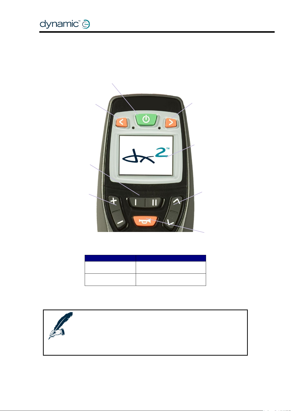
Note:
The function of the plus/minus button and the up/down button can be
swapped with the Left-Right Mounting parameter (see 4.2.1.1).
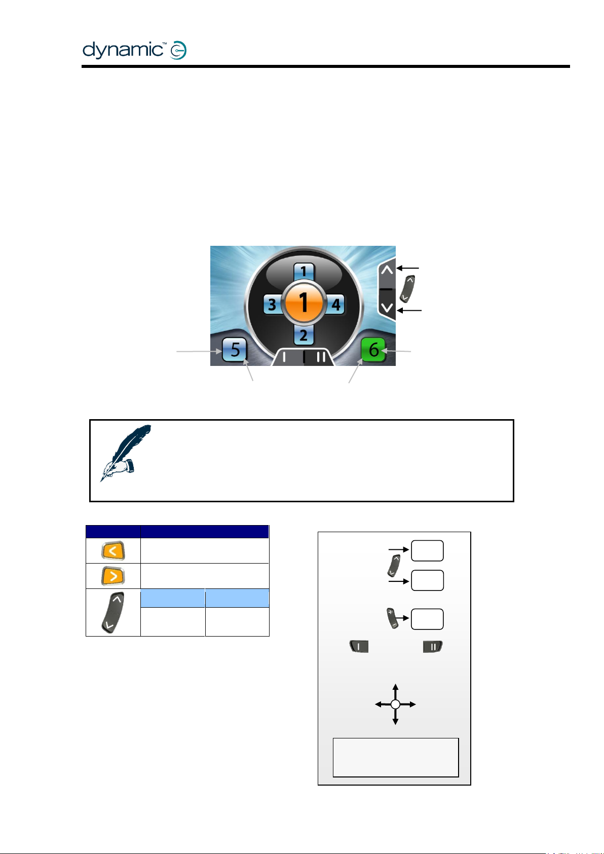
All the menu navigation descriptions and screen layouts in this manual are
applicable to the ‘[+ -]Drive [^ v]Accessory’ setting.
On/Off button
Left indicator
(DX2-REM550)
Screen
Right indicator
(DX2-REM550)
Function
keys
Horn
Accessory Mode
Drive Profile
selection
2 DX2 AJR Operation
2.1 The keypad
button
button
selection
8 GBK60348: Issue 3
Page 9
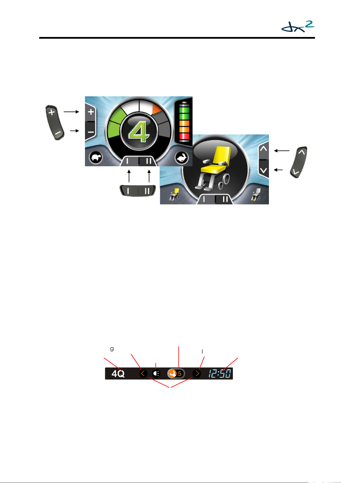
Operating
Left Indicator
Active
Right
Active
Clock
Side Light
System Status
Hazard Lights Active
2.2 The Screen
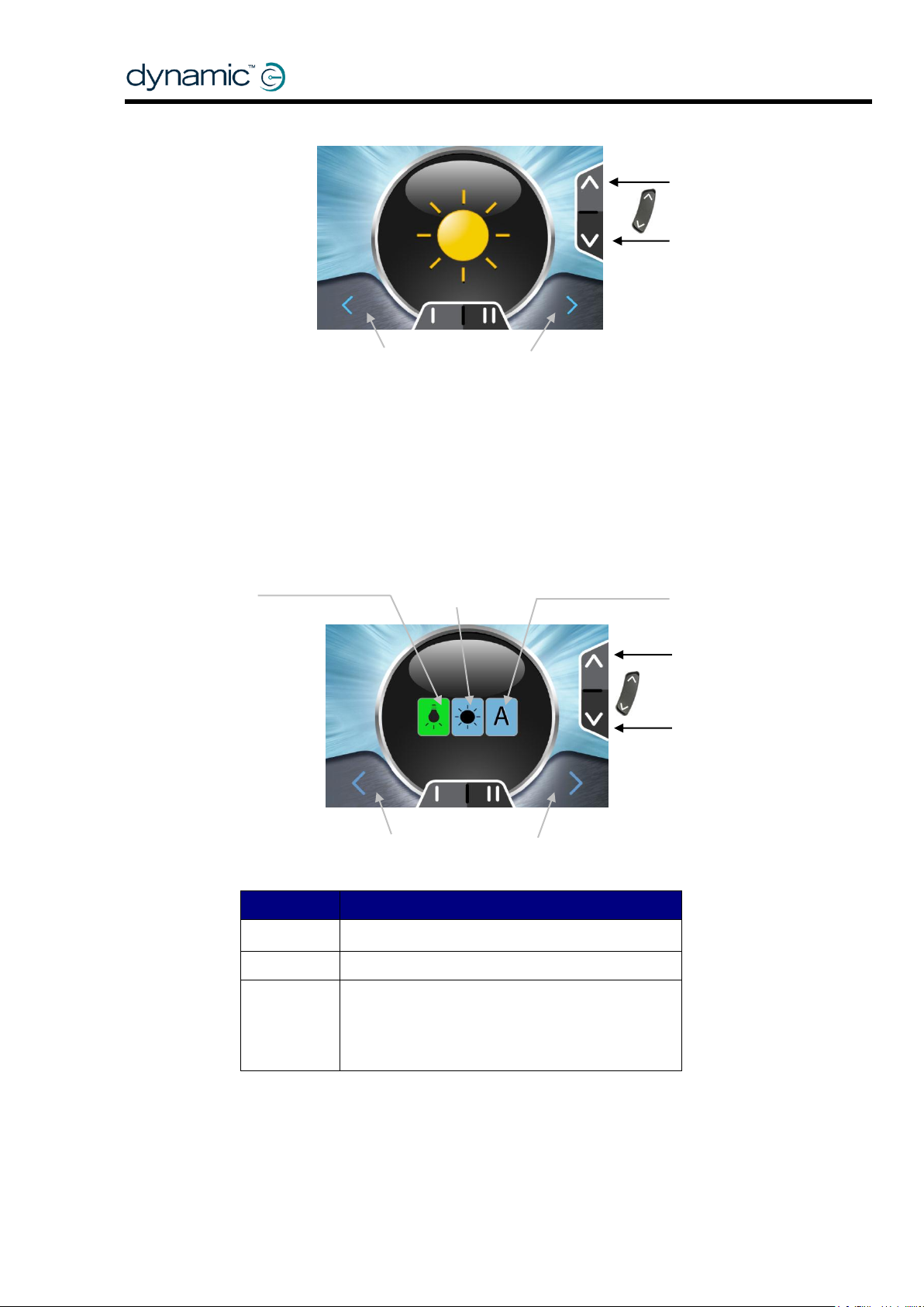
2.2.1 Screen Layout
The screen layout varies depending on the selected mode – Drive Mode (left-hand
screen above), and Accessory Mode (right-hand screen above).
The area at the centre of the screen shows the mode that is currently active.
2.2.2 The Status Bar
The status bar is located at the top of the screen. The status bar shows the operating
mode (standard or 4Q), the lighting icons, the System Status and the clock.
Mode
Indicator
Active
GBK60348: Issue 3 9
Page 10
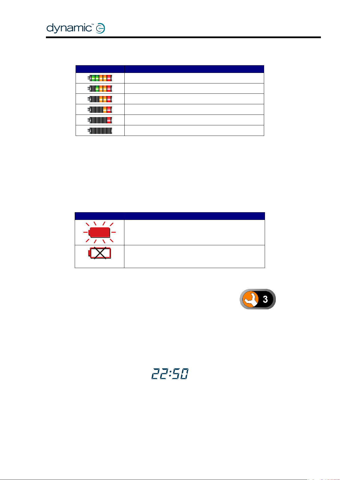
Battery Gauge
Meaning
Battery full
Battery almost full
Battery half full, drive towards a charger
Battery low, recharge soon
Battery almost empty, recharge now
Battery empty, recharge immediately
Warning Icon
Meaning
Battery overcharged.
Slow down and turn on the lights (if fitted).
+ Horn beeps
Battery completely empty. System turns off.
Recharge.
The Battery Gauge 2.2.2.1
The Battery Gauge indicates how much battery charge remains.
The remaining battery capacity does not translate directly to remaining physical
range of the powerchair. The remaining physical range depends on the ambient
temperature, the capacity and age and state of the battery, the driving style of the
operator and the terrain that the powerchair is being used in. Most of these factors
can vary between, or within, one journey.
Battery Warnings
Battery warnings are shown at the centre of the screen, in the "Active Mode" area.
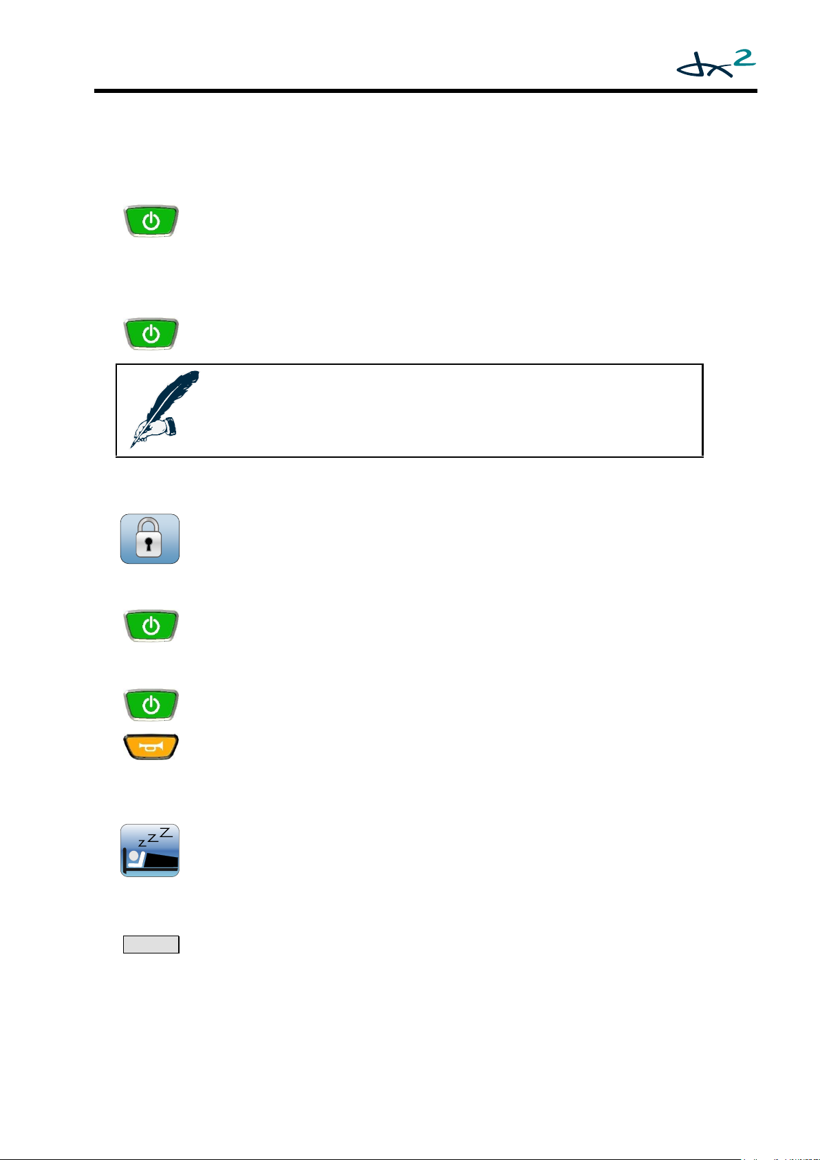
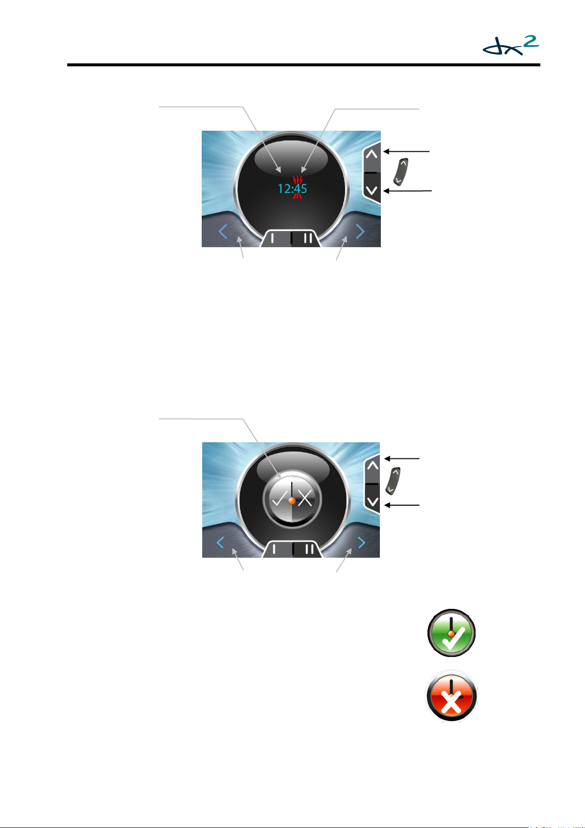
The System Status 2.2.2.2
The System Status icon is normally hidden. If a fault occurs, a
wrench icon will show, together with the fault code number. See
the DX System Manual for a description of the fault codes (DSM
section 9.6).
The Lighting Icons 2.2.2.3
The indicator icons and the side light icon will show when the lights are on.
Section 2.5.1 describes how to operate the lights.
The Clock 2.2.2.4
The clock shows the time in 24-hour format. The time can be adjusted with the OnBoard Programming menu. See Adjust the clock (2.5.3.3).
10 GBK60348: Issue 3
Page 11
To turn on the DX System
Press the power button.
The AJR will beep twice (if the Mode Change Beep parameter,
see 4.2.1.10, is set to ‘Yes’) and the system will start up in
Drive Mode (see 2.5.1) with the Drive Profile that has been set with the
Power-Up Profile Number parameter (see 4.2.1.13).
To turn off the DX System
Press the power button.
The DX System will turn off.
Note:
If the power button is pressed while the chair is driving,
the chair will perform an emergency stop before it turns off.
To lock the DX System
Press the power button for 4 seconds when the DX System is turned on.
The DX System will turn off in a locked state.
To unlock the DX System
Press the power button.
The AJR will show a lock on the display.
Press the horn button twice within 10 seconds.
The DX System will turn on normally.
To wake up the DX System
Any key
or
Joystick
Press any button on the AJR, or, if the Enable Joystick Wakeup parameter
(see DSM 5.3.9.10) is set to 'Yes', move the joystick.
The DX System will turn on.
2 x
2.3 Turning the DX System on and off with the AJR
2.3.1 System Lock
If the Lock Enable parameter (see DSM section 5.3.9.7) is set to 'Yes', the
system can be locked by pressing the power button for more than
4 seconds.
2.3.2 Sleep mode
If the Sleep Mode Enable parameter (see DSM 5.3.9.8) is set to 'Yes', the
DX System will go to sleep after a period of inactivity. This period can be set
with the Sleep Timeout parameter (see DSM 5.3.8.5). When the DX System
sleeps, it is partially turned off to reduce energy consumption.
GBK60348: Issue 3 11
Page 12
Note:
The orientation of the joystick depends on the value of the Accessory
Menu Navigation (4.2.1.6) parameter.
The description of the menus in this manual assumes that this
parameter has the value ‘Normal’.
Note:
If the Drive Profile selection buttons on the AJR are pressed during
Attendant Mode, the AJR will return to Drive Mode (if it currently is not
in Drive Mode), but it will not change the Drive Profile. The attendant
Drive Profile will stay active until the attendant releases control back
to the user.
2.4 Menu Navigation Modes
2.4.1 Standard Mode
In Standard Mode the menu navigation is mostly performed with the plus/minus
(Drive Profile selection) and up/down (Accessory Mode selection) buttons. Some
functions can be accessed directly with other buttons (for example the indicator
buttons or the function buttons).
The joystick is used in some modes to operate within that mode. For example, in
Actuator Mode the joystick operates a selected actuator.
In this manual, a menu map is included with each menu mode. The menu map shows
the exact menu navigation for each mode.
For menu navigation in Standard Mode, see section 2.5.1.
2.4.2 Attendant Mode
Attendant Mode is selected when the attendant switch on the
attendant control is switched to local. When the Attendant Mode is
selected, the attendant icon will be shown on the screen. Use the
Accessory Mode selection button to select different operating
modes.
During Attendant Mode all menu navigation is identical to Standard Mode (all
buttons on the AJR will work the same) with the only difference being that the joystick
navigation (for example when using actuators) is taken over by the attendant
joystick. For this reason no separate menu navigation is given for Attendant Mode.
12 GBK60348: Issue 3
Page 13
Notes:
The orientation of the joystick depends on the value of the Accessory
Menu Navigation (4.2.1.6)parameter.
The description of the menus in this manual assumes that this
parameter is set to ‘Normal’.
Warning:
If in 4Q menu navigation mode, and Reverse Escape Enable (4.2.1.16)
and Escape Timeout (4.2.1.17) are both disabled, it is only possible to
return to the home level by using the applicable buttons on the
keypad.
If the user is not able to use the buttons on the keypad, make sure to
either set Reverse Escape Enable to 'yes' or set Escape Timeout to a
value greater than zero when using 4Q menu navigation mode.
2.4.3 Four-Quadrant (4Q) Mode
Four-quadrant mode is a joystick-only mode for navigating the menus.
All menus are accessible by deflecting the joystick.
Each Drive Profile can be set to 4Q Mode or Standard Mode separately. Set the
Joystick Only Operation parameter (see 4.2.1.15) to 'Yes' in all Drive Profiles for which
4Q Menu Navigation Mode is desired.
The 4Q menu structure has extra features such as 'horn' and 'force sleep'. These
features are in Standard Mode too, but are only accessible with the buttons of the
AJR.
The menu structure of 4Q mode starts at the 'home level'.
Scroll through the desired Modes (drive, accessory, etc.) with joystick left/right.
Enter the desired Mode with joystick forward.
To exit a Mode:
o If Reverse Escape Enable (4.2.1.16) has the value 'yes': deflect the joystick reverse
to return to the home level.
o Wait for Escape Timeout (4.2.1.17) seconds and the menu will automatically
return to the home level.
o Press the accessory button to return to the home level.
Most AJR buttons will still work the same as in Standard Mode.
For 4Q menu navigation see section 2.6.
GBK60348: Issue 3 13
Page 14
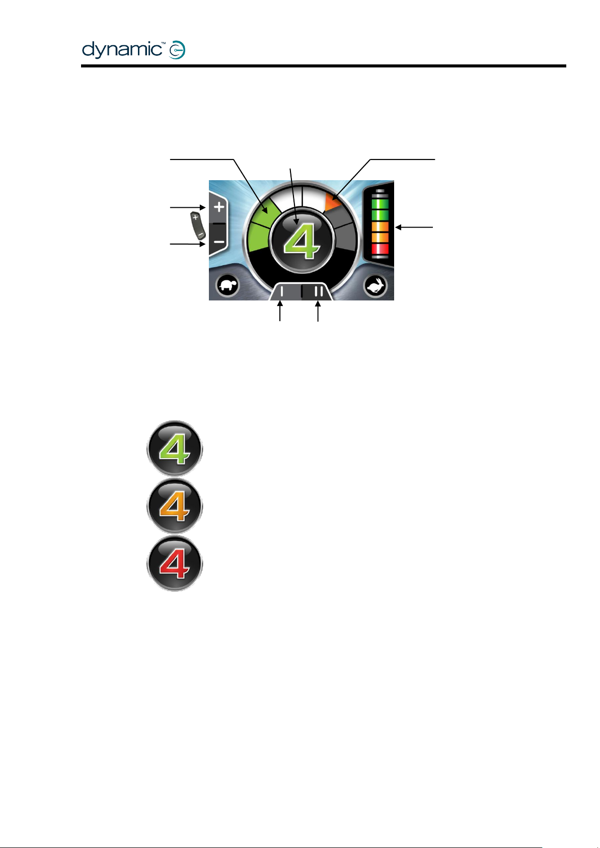
A green Drive Profile shows a normal drive
operation.
An orange Drive Profile is displayed to indicate
that a chair can drive, or is driving in a restricted
capacity – that is, reduced speed.
A red (flashing) Drive Profile indicates that the
chair is in an inhibited state – the chair cannot
be driven in this state.
Current
Drive Profile
Current
Speed
Maximum
Speed
Battery Gauge
Select next
Drive Profile
Select previous
Drive Profile
The operation of the function keys is dependent
parameter (see 4.2.1.3).
2.5 Standard Menu Navigation
2.5.1 Drive Mode - Standard
The colour of the current Drive Profile, shown in the middle of the screen, is
dependent on the chair’s status.
on the value of the [I II] Function Button
The Function Button allows hot key access to favourite functions during normal
operation. Common uses include fine tuning of speed within a drive profile, or instant
access to one or two favourite seating functions e.g. tilt or recline. The function button
allows simultaneous operation with drive commands so users can adjust seat positions
whilst driving.
14 GBK60348: Issue 3
Page 15
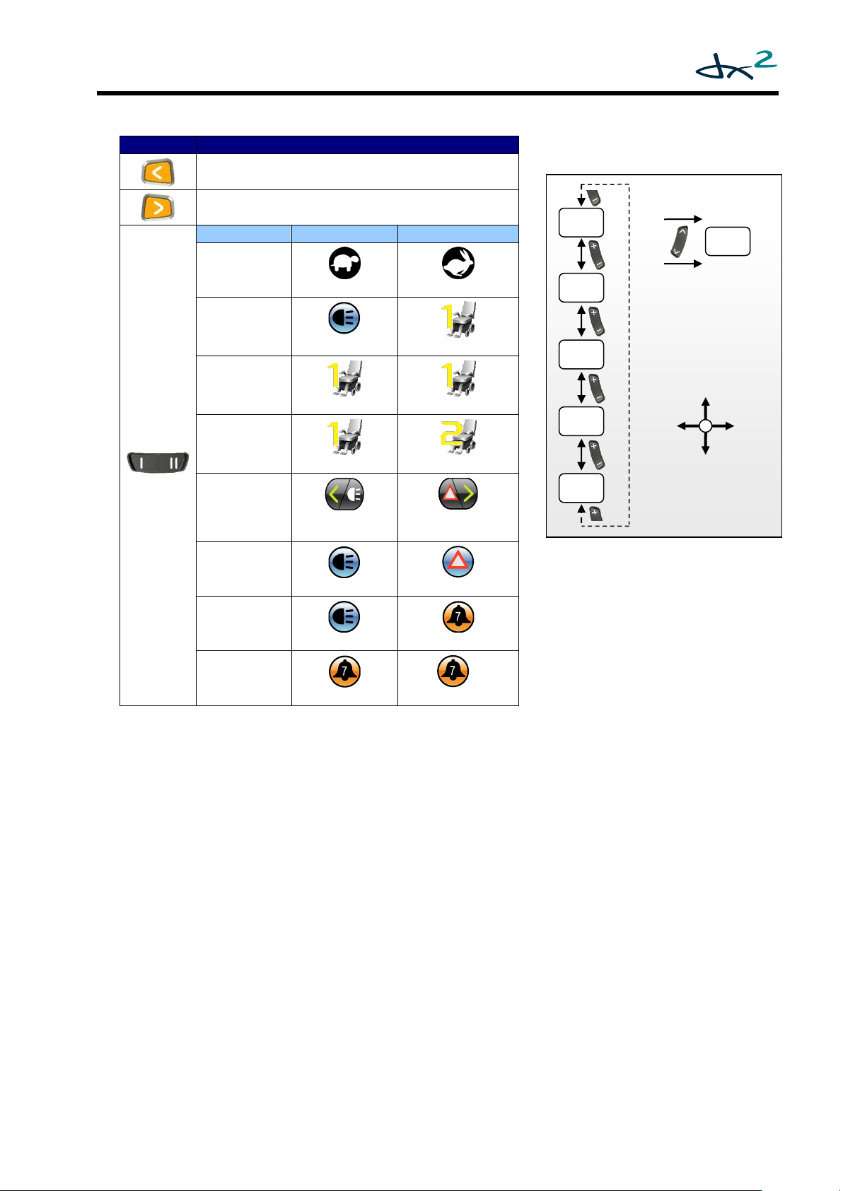
Button
Function
Left Indicator
>2s: Side lights
Right Indicator
>2s: Hazard lights
Function I II
Speed Pot
slower
faster
Warning +
Actuator
Side lights
Actuator Aux1
Actuator
up + down
Actuator Aux1 up
Actuator Aux1 down
Two Actuators
Actuator Aux1
Actuator Aux2
Full Lighting
Left indicator
> 2s: Side lights
Right indicator
>2s: Hazard lights
Warning +
Hazard
Side lights
Hazard lights
Warning +
ECU alarm
Side lights
ECU Alarm
ECU Alarm +
Toggle ECU Al.
ECU Alarm
ECU Alarm Latched
L
Drive Mode Menu Map
P2
P3
P4
P5
If Wrap Profiles (DSM 5.3.8.2) is set to 'Yes'
Drive
Left
Drive
Right
Drive
Fwd
Drive
Rev
*if available
Act.*
P1
Joystick
GBK60348: Issue 3 15
Page 16
Mode
Active
Parameter(s)
Actuators
Depends on enabled
actuators
iPortal2
Set ‘Allow non-driving
profile’ to ‘Yes’. See
DSM section 5.3.8.4
Allow Non-Driving
Profile
Lights
Lighting Menu (0)
ECU 1
Mouse
ECU Menu (4.2.1.9)
ECU 2
ECU Menu (4.2.1.9)
Program
Screen
Settings
OBP Menu (4.2.1.7)
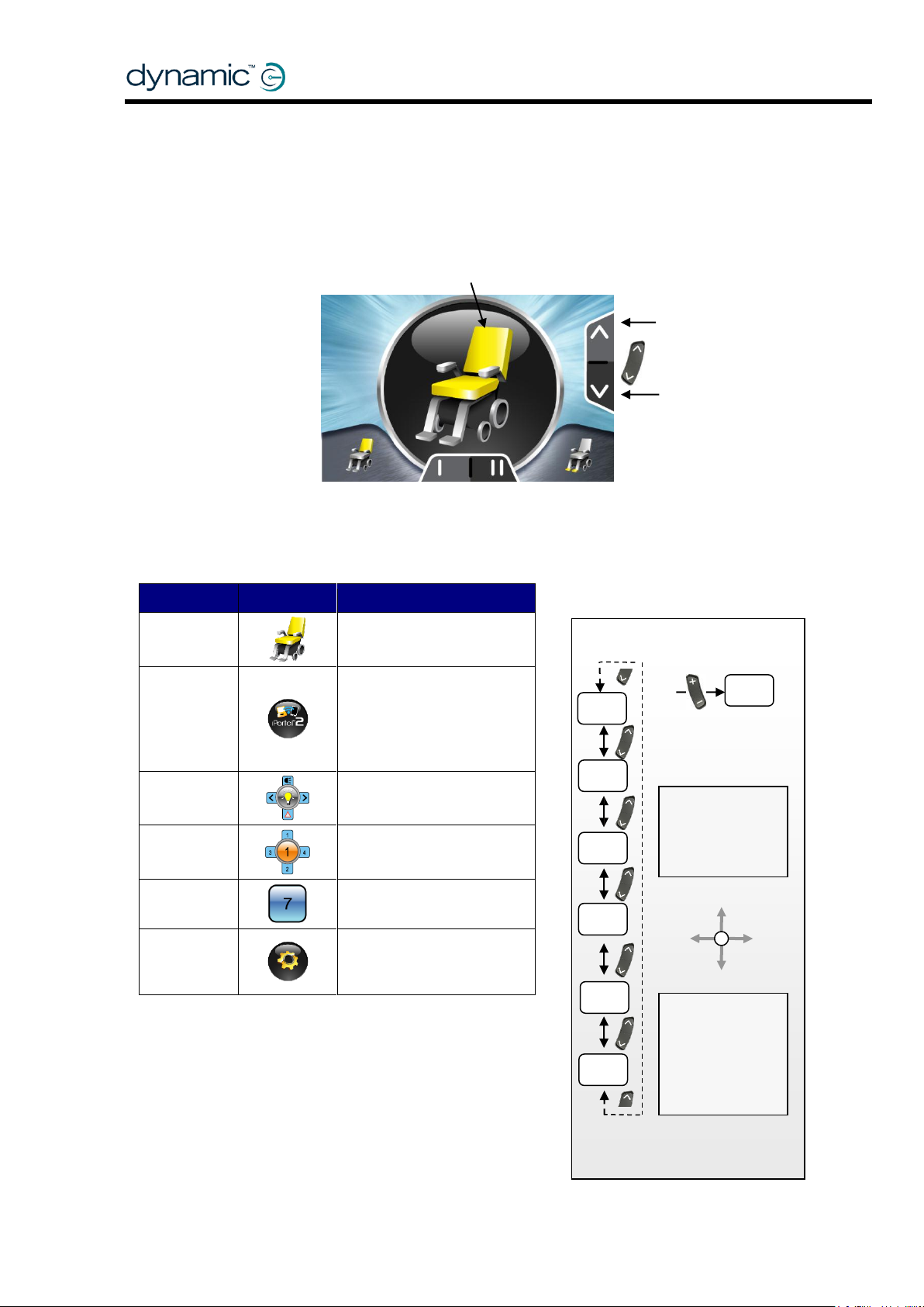
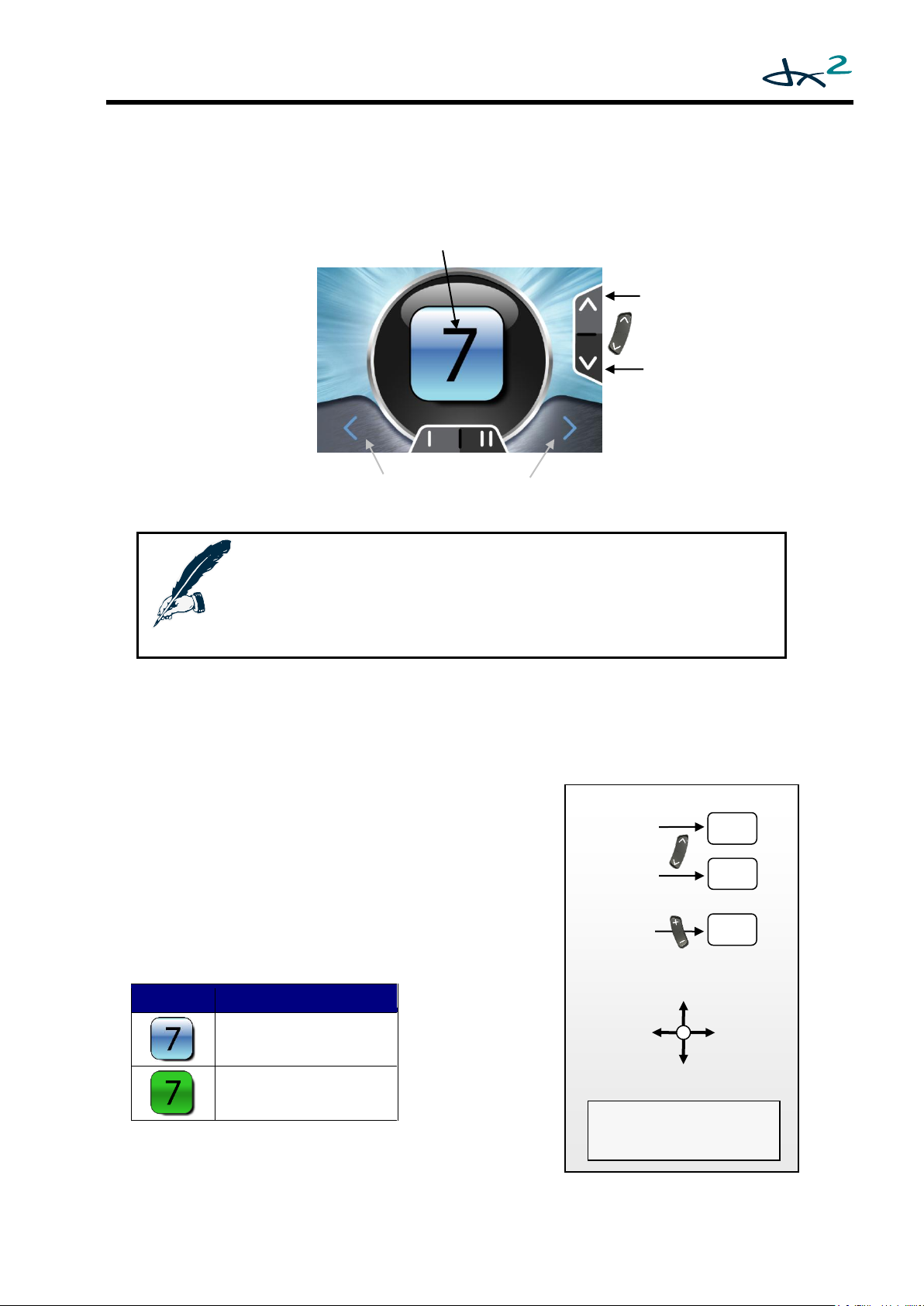
Active Accessory
(Actuator Mode shown)
Next
Accessory
Mode
Previous
Mode
Accessory Mode Menu
OBP
Lights
ECU1
iPortal2
The operation of
Accessory Mode.
Accessory
accessory list.
Drive
Act
ECU 2
2.5.2 Accessory Mode – Standard
Accessory Modes are available:
when the presence of that accessory is detected in the DX System;
when the menu of that accessory has been enabled with its corresponding
menu enable parameter (see sections 4.2.1.7 to 4.2.1.9).
Accessory
When the Accessory Mode button is pressed (either Next or Previous) the menu will
always start at the Seating Accessory screen (if actuators are active).
Modes that are
not available are
not shown in the
16 GBK60348: Issue 3
the keypad and
the joystick is
dependent on
the currently
selected
Page 17
Note:
The orientation of the joystick depends on the value of the Accessory
Menu Navigation (4.2.1.6) parameter.
The description of the OBP menu assumes that this parameter has the
value ‘Normal’.
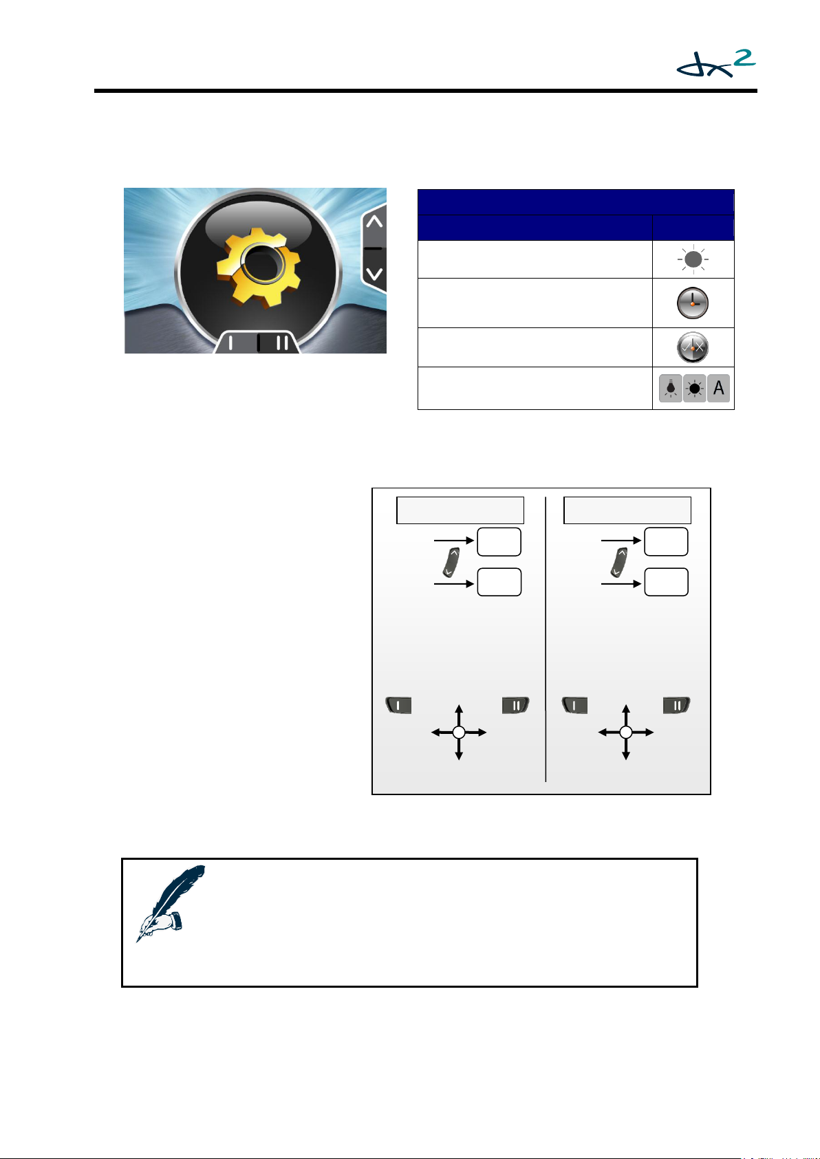
OBP Menu Items
Menu Item
Icon
Screen Brightness
Clock adjustment
Clock visible (yes/no)
Screen Environment
(inside/outside)
OBP Mode Menu Map
Next
Acc
Prev .
Acc
Activate
Menu Item
Prev.
Item
Next
Item
Exit
Item
Exit
Item
Accept
Value
Exit Menu Item
Adjust
Value
Adjust
Value
Menu Item Not Active
Menu Item Active
2.5.3 On-Board Programming (OBP) Mode – Standard
The OBP menu is available when OBP Menu (see 4.2.1.7) has the value 'Yes'.
The cog, displayed above, indicates the
OBP top-level menu item. To activate (or
drill down to) the OBP menu, deflect the
joystick forward.
OBP menu navigation:
Use the function buttons or
joystick left/right to select the
next or the previous menu item.
To activate the desired menu
item, deflect the joystick
forward.
In the active menu item, use
the function buttons or joystick
left/right to adjust the value of
the selected item.
Deflect the joystick forward to
accept the new value.
Deflect the joystick reverse to
exit the menu item and return
to the OBP main menu.
GBK60348: Issue 3 17
Page 18
Setting
Result
Indoors
The screen has a black background.
Outdoors
The screen has a white background.
Automatic
The environment setting (inside or outside)
is set automatically depending on the
amount of ambient light.
The function keys change the screen brightness value.
Exit
Exit
The function keys select the screen environment.
Indoors
Exit
Cancel
Exit
Cancel
Automatic
Outdoors
OBP Screen Brightness 2.5.3.1
Use either the function buttons or joystick left/right to change the screen
brightness.
Use joystick forward/reverse or the accessory buttons to accept the new setting
and return to the main OBP menu.
OBP Screen Environment Setting (Indoors/Outdoors) 2.5.3.2
Use either the function buttons or joystick left/right to select the environment.
Use joystick forward to accept the new setting and return to the main OBP menu.
Use joystick reverse or the accessory buttons to cancel the new setting and return
to the main OBP menu.
18 GBK60348: Issue 3
Page 19
Use either the function buttons or joystick left/right to toggle
the on/off status.
Deflect the joystick forward to accept the new status and
return to the main OBP menu.
Use the accessory buttons to cancel the new status and
return to the main OBP menu.
The function keys toggle the on/off status of the clock.
Current
State
Exit
Cancel
Exit
Cancel
The function keys select an individual digit.
New
Time
Exit
Cancel
Exit
Cancel
Active digit
blinks
Adjust the clock 2.5.3.3
Use either the function buttons or joystick left/right to select a different digit.
Deflect the joystick forward to increase the value of the digit.
Deflect the joystick reverse to accept the new time and return to the main OBP
menu.
The accessory buttons cancel the new time (keep the original time) and returns
the display to the main OBP menu.
Clock Visible 2.5.3.4
GBK60348: Issue 3 19
Page 20
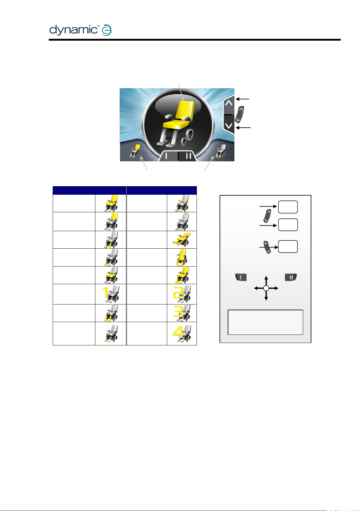
Function
Active
Function
Active
F1 - Tilt
F14 - Arm rest
F2 -Recline
F26 - Head
F3 - Left leg
F28 - Lie down
F4 -Right Leg
F33 - Stand up
F5 - Seat
F34 - Sit down
F6 - AUX1
F35 - AUX2
F9 - Both legs
F36 - AUX3
F11 - Footplate
F37 - AUX4
Active Actuator Function
Next
Accessory
Mode
Previous
Mode
The function keys scroll through
the available actuator functions.
Actuator Mode Menu
Rotate the orientation of
Menu Navigation (4.2.1.6).
Extend
Retract
Previous
Actuator
Next
Actuator
Next
Acc
Prev .
Acc
Drive
2.5.4 Actuator Mode – Standard
Accessory
the joystick with Accessory
DX2 Mode (for the DX2 Actuator Modules)
You can assign any of the icons listed above to a programmed Actuator Function/Profile by
setting the Input Function Number parameter of that Actuator Profile accordingly.
For example, if an Actuator Profile has Input Function Number 28, the lie down icon will be
shown for that Actuator Profile. Only the icons that have been assigned to an Actuator
Profile are shown in the menu, if the Actuator Module that contains this Actuator Profile is
actually detected in the system.
20 GBK60348: Issue 3
Page 21
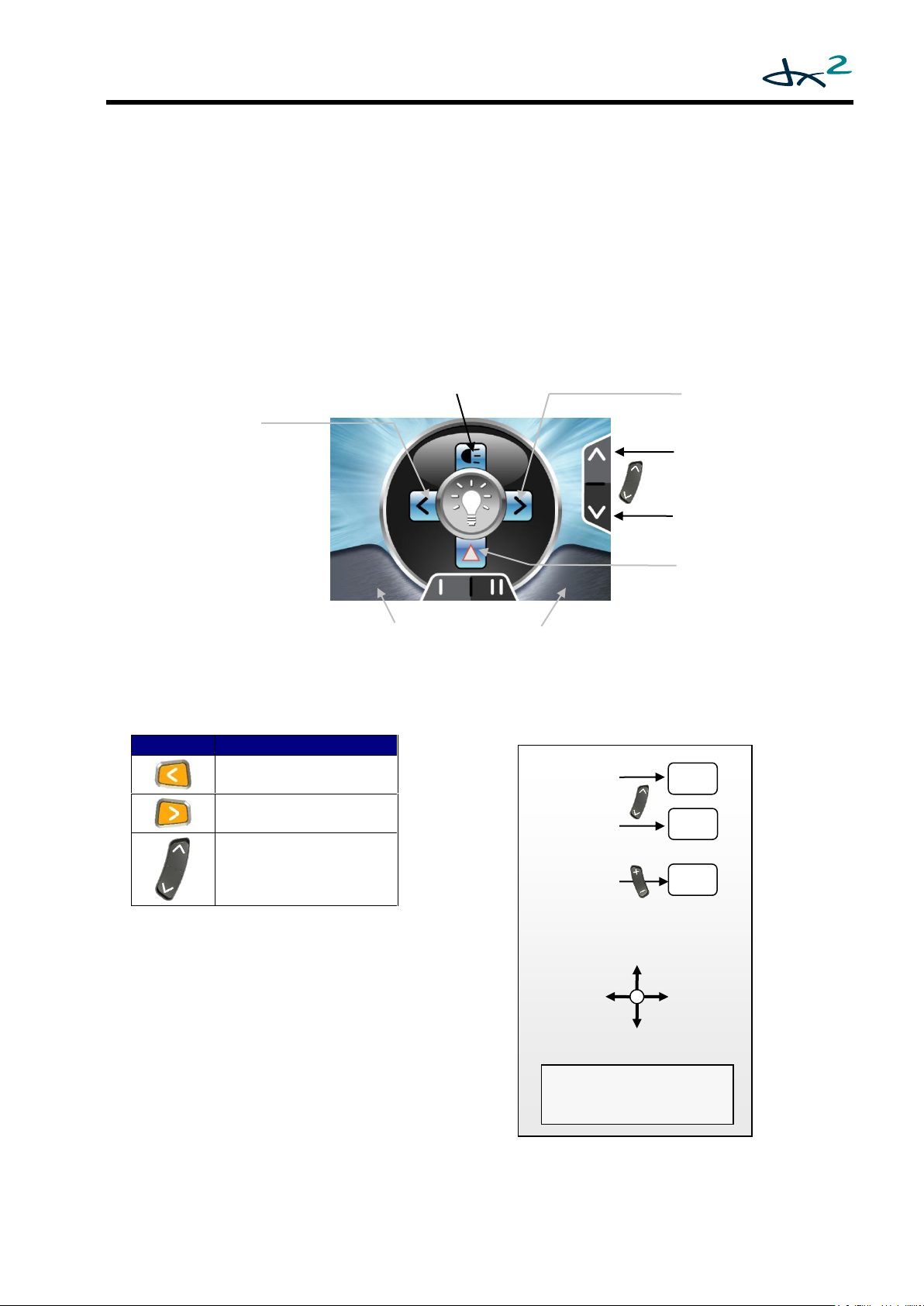
Button
Function
Left Indicator
>2s: Side lights
Right Indicator
>2s: Hazard lights
Not active
Lighting Mode Menu Map
Rotate the orientation of
Menu Navigation (4.2.1.6).
Side
Lights
Hazard
Lights
Left
Indicator
Right
Indicator
Next
Acc
Prev .
Acc
Drive
The function keys are not active in this mode.
Left
Indicator
Previous
Accessory
Hazard
Lights
Next
Accessory
Right
Indicator
Side
Lights
DX Mode (for the CLAM/TAM)
Functions F1 - F5 operate actuators 1 - 5. Function F9 operates actuators 3 + 4 simultaneously.
Only the actuators that have been enabled are shown in the menu. If actuator 3 and 4 are
both enabled, function 9 is added to the menu automatically.
2.5.5 Lighting Mode – Standard
The lighting menu is available when:
the CLAM Lighting Enable parameter (see DSM section 6.6.2.1) has the value
'Yes';
a CLAM or lighting module is detected in the system;
the Lighting Menu parameter (4.2.1.8) is set to 'Yes'.
Deflect the joystick to turn the associated light on or off.
GBK60348: Issue 3 21
the joystick with Accessory
Page 22
Notes:
Channel operation is not latched in ECU1 Mode. The channel
will return to the 'off' state when the joystick is returned to neutral.
Button
Function
Left Indicator
>2s: Side lights
Right Indicator
>2s: Hazard lights
I
II
Channel 5
Channel 6
The joystick operates
ECU1 channel 1to 4
Next
Accessory
Previous
Accessory
The function keys operate ECU1 channel 5 and 6.
Green:
Channel active
Blue: Channel
ECU1 Mode Menu Map
Next
Acc
Prev
Acc
Rotate the orientation of
Menu Navigation (4.2.1.6).
Channel 1
Channel 2
Channel 3
Channel 4
Drive
Channel 5
Channel 6
2.5.6 ECU1 Mode (ECU mouse control) – Standard
ECU1 Mode gives access to the first 6 channels of an Environmental Control Unit
Module (ECU) that has been setup as ECU1. These channels are generally used for
mouse or communications control. For access to channels 7 and 8 of ECU1 use the
ECU2 menu.
This mode is only available if the ECU Mouse Mode Menu parameter (see 4.2.1.9) is set
to 'Yes' and an ECU Module is detected in the system.
not active
22 GBK60348: Issue 3
the joystick with Accessory
Page 23
Note:
This mode is only available if one of the ECU Menu parameters (see 4.2.1.9) is
set to 'Yes' and an ECU Module is detected in the system.
Only the enabled channels will be shown.
Icon
Meaning
Channel is off
Channel is on
Selected channel
Next
Accessory
Previous
Accessory
The function keys scroll through the available channels.
ECU2 Mode Menu Map
Rotate the orientation of
Menu Navigation (4.2.1.6).
Toggle selected
channel - not latched
Toggle selected
channel - latched
Previous
Channel
Next
Channel
Next
Acc
Prev .
Acc
Drive
2.5.7 ECU2 Mode – Standard
ECU2 Mode gives access to channel 7 and 8 of an ECU Module that has been setup
as ECU1, and to all 8 channels of an ECU Module that has been setup as ECU2.
The 8 channels of ECU2 are numbered 9-16.
Deflecting the joystick forward or reverse toggles
the selected channel: when the channel is off,
it turns on, when the channel is on, it turns off.
If the joystick is deflected reverse, the channel
will stay in the new state (on or off) when the
joystick is returned to neutral (latched operation).
If the joystick is deflected forward, the channel
will return to its original state when the joystick
is returned to neutral (not-latched operation).
iPortal Accessory Mode – Standard
iPortal Accessory Mode – Standard
the joystick with Accessory
GBK60348: Issue 3 23
Page 24

The iPortal accessory screen appears in
the menu if "Allow Non-Drive Profile" has
been set to YES (Drive Profile 0). This
profile uses the input source allocated to
Drive Profile 1. The intended use of this
mode is for proportional control of iPortal
from a joystick source. For switch input
control of iPortal, such as with a head
control, it is best to use ECU1 as the
operating channels.
For a full description of iPortal functionality refer to the relevant iPortal user guides and
installation manuals.
2.5.8 iPortal Accessory Mode – Standard
24 GBK60348: Issue 3
Page 25

Warning:
If in 4Q menu navigation mode, and Reverse Escape Enable
(4.2.1.16) and Escape Timeout (4.2.1.17) are both disabled, it is only
possible to return to the home level by using the applicable buttons
on the keypad.
If the user is not able to use the buttons on the keypad, make sure to
either set Reverse Escape Enable to 'yes' or set Escape Timeout to a
value greater than zero.
Horn
Lights
Act.
OBP
ECU2
Drive
Sleep
L
R L R L R L R L R
R
L
R
L
Accessory Modes
accessory list.
4Q Home Level Menu Map
+/-
Drive
Previous
Mode
Next
Mode
Enter
Mode
Enter
Drive Mode*
*Skips the Profile
Selection Mode, ready
to drive immediately.
L
R
ECU1
L
R
iPortal2
2.6 4Q Menu Navigation - Home Level
The menu structure of the 4Q navigation mode starts at the 'Home
Level'. The Home Level of the 4Q menu is very similar to the standard
Accessory Mode (see 0).
the up/down buttons or joystick left/right scrolls through the different accessories;
the plus/minus buttons or joystick reverse enters Drive Mode.
Drive Mode is inserted in the 'accessory' list, as well as Sleep Mode and Horn Mode. In
Standard Mode these features are only accessible with the keypad.
that are not available
are not shown in the
To exit from a Mode to the Home Level:
If Reverse Escape Enable (4.2.1.16) has the value 'yes': deflect the joystick
reverse to return to the Home Level.
For all modes, except iPortal2, wait for Escape Timeout (4.2.1.17) seconds and
the menu will automatically return to the home level. For iPortal2, the menu
returns to the home level after Mouse Inactivity Timeout has expired.
Press the accessory button to return to the Home Level.
GBK60348: Issue 3 25
Page 26

P. Sel.
P. Sel.
L R L R L
R
P. Sel.
Home
Drive
Fwd
Rev
Fwd*
L
R
Rev** / Wait***
Rev
Rev
4Q Drive Mode Menu Map
Left
Right
Forward
Reverse / Exit to Home Level**
Previous
Mode
Next
Mode
Profile Selection Mode
Drive Mode
Previous
Profile
Next
Profile
Drive Mode
Cancel - to Home Level
* If the selected Drive Profile does not have Joystick Only Operation set to 'Yes', entering
Drive Mode
Prof. Sel. Mode
Home Level
2.6.1 Drive Mode – 4Q
Drive Mode starts at the Drive Home Level (see 2.6).
Deflect the joystick forward to enter the Drive Profile Selection Mode.
In Drive Profile Selection Mode the Drive Profile flashes.
Select the desired Drive Profile by deflecting the joystick left/right.
Deflect the joystick forward to enter Drive Mode*.
In Drive Mode the speedometer appears.
Deflect the joystick to drive.
Use the plus/minus buttons to change the Drive Profile.
To exit Drive Mode:
If Reverse Escape Enable (4.2.1.16) has the value 'yes': deflect the joystick reverse
to return to the Drive Home Level.
Wait for Escape Timeout (4.2.1.17) seconds and the menu will automatically return
to the Drive Home Level.
Press the up/down button to return to the Home Level of the next/previous Mode.
Drive Mode will automatically exit 4Q Mode
** Depending on the value of the Reverse Escape Enable parameter
*** Depending on the value of the Escape Timeout parameter
26 GBK60348: Issue 3
Page 27

Sleep
Home
Fwd
Any button, or
Any joystick deflection*
4Q Sleep Mode Menu Map
Previous
Mode
Next
Mode
Go to sleep
Drive Mode
Wake
Up*
Wake
Up*
Wake Up*
Wake Up*
*Depending on the value of the Enable
Joystick Wakeup parameter, see DSM 5.3.9.10
Sleep Mode
Home Level
Home
Menu Map
Previous
Mode
Next
Mode
Sound Horn
Drive Mode
2.6.2 Force Sleep Mode – 4Q
In addition to the automatic sleep timeout that can be set with the Sleep Mode
Enable parameter (see DSM 5.3.9.8), the Force Sleep Mode can put the AJR to sleep
immediately.
Sleep Mode starts at the Sleep Home Level (see 2.6).
Deflect the joystick forward to enter Sleep Mode (go to sleep)
The DX System switches off.
To wake up (switch on) the DX System:
Press any button on the keypad.
If Enable Joystick Wakeup (DSM 5.3.9.10) has the value 'yes', deflect the joystick in
any direction.
The AJR starts up in the Drive Home Level (see 2.6.1).
2.6.3 Horn Mode – 4Q
Horn Mode starts at the
Horn Home Level (see 2.6).
Deflect the joystick forward to sound the horn.
GBK60348: Issue 3 27
Page 28

OBP Menu Items
Menu Item
Icon
Menu Item
Icon
Screen Brightness
Clock adjustment
Screen Environment
(inside/outside)
Clock visible (yes/no)
Note:
The orientation of the joystick depends on the value of the Accessory
Menu Navigation (4.2.1.6) parameter.
The description of the OBP menu assumes that this parameter is set to
‘Normal’.
Clock
In/Out
R R
R
Bright
Fwd*
Fwd*
R Left/Rev
Fwd*
4Q OBP Mode Menu Map
Previous
Mode
Next
Mode
Item Selection Mode*
Drive Mode
Home
Level
Next
Item
Activate Item
Home Level
*Item Selection Mode will show the last selected Item
Item Selection
Home Level
Home
Visible
Fwd*
2.6.4 On-Board Programming (OBP) Mode – 4Q
The OBP menu is available when OBP Menu (see 4.2.1.7) has the value 'Yes'.
OBP Mode starts at the OBP Home Level (see 2.6).
Deflect the joystick forward to enter the OBP Item Selection Mode
Item Selection Mode will start up with the item that was last
selected.
To select the desired menu item, deflect the joystick to the right. Alternatively, the
function buttons (I/II) can also be used to scroll through the available menu items.
To activate the selected menu item, deflect the joystick forward.
28 GBK60348: Issue 3
Page 29

Setting
Result
Indoors
The screen has a black background.
Outdoors
The screen has a white background.
Automatic
The environment setting (indoors or
outdoors) is set automatically depending
on the amount of ambient light.
The function key changes the brightness value.
Exit
Accept
Exit
Accept
The function keys select the environment.
Indoors
Exit
Cancel
Exit
Cancel
Automatic
Outdoors
4Q Menu Map
Exit
Accept
Exit
Accept
More Brightness
Less Brightness
4Q Menu Map
Exit
Accept
Exit
Accept
Change Setting
Exit - Cancel
OBP Screen Brightness 2.6.4.1
Deflect the joystick forward/reverse or use the function
buttons to change the screen brightness.
Deflect the joystick left/right or the accessory buttons
to accept the new setting and return to the
OBP Item Selection menu.
OBP Screen Environment Setting (Indoors/Outdoors) 2.6.4.2
Deflect the joystick forward or the function buttons
to select the environment.
Deflect the joystick left/right to accept the new setting and
return to the OBP Item Selection menu.
Deflect the joystick reverse to cancel the new setting and
return to the OBP Item Selection menu.
Use the accessory buttons to cancel the new setting
and return to the OBP Home Level.
GBK60348: Issue 3 29
Page 30

The function keys toggle the on/off status of the clock.
Exit
Cancel
Exit
Cancel
The function buttons select a different digit.
New
Time
4Q Mode
Active
Exit
Cancel
Exit
Cancel
Select
Drive Mode
Active digit
blinks
4Q Menu Map
Exit
Accept
Select
Act. Digit
Change Value
Exit - Cancel
4Q Menu Map
Exit
Accept
Exit
Accept
Change Setting
Exit - Cancel
Adjust the clock 2.6.4.3
Deflect the joystick right or use the function buttons
to select the active digit.
Deflect the joystick forward to increase
the value of the digit.
Deflect the joystick left to accept the new time and
return to the OBP Item Selection menu.
Deflect the joystick reverse to cancel the new time and
return to the OBP Item Selection menu.
Use the accessory buttons to cancel the new time and return to the OBP Home
Level.
Set Clock Visible 2.6.4.4
Deflect the joystick forward or use the function buttons
to toggle the on/off status.
Deflect the joystick left/right to accept the new status and
return to the OBP Item Selection menu.
Deflect the joystick reverse to cancel the new status and
return to the OBP Item Selection menu.
Use the accessory buttons to cancel the new status
and return to the OBP Home Level.
30 GBK60348: Issue 3
Page 31

Note:
In 4Q Lighting Mode the lights can
also be operated with the
indicator buttons on the keypad:
Button
Function
Left Indicator
>2s: Side lights
Right Indicator
>2s: Hazard lights
Lights
Home
Fwd
4Q Lighting Mode Menu Map
Previous
Mode
Next
Mode
Lighting Mode
Drive Mode
Exit
Accept
Next
Mode
Side Lights
Hazard Lights
Lighting Mode
Home Level
Ind.
Left
Left
Right
Right
Exit
Accept
Next
Mode
Right Indicators
Left Indicators
2.6.5 Lighting Mode – 4Q
The lighting menu is available when:
the CLAM Lighting Enable parameter (see DSM section 6.6.2.1) has the value
'Yes';
a CLAM or lighting module is detected in the system;
the Lighting Menu parameter (4.2.1.8) is set to 'Yes'.
Lighting Mode starts at the Lighting Home Level (see 2.6).
Deflect the joystick forward to enter Lighting Mode.
Lighting Mode starts up in the Lights Mode.
Deflect the joystick right to enter the next Lighting Mode.
Deflect the joystick Forward or Reverse to turn the associated light on or off.
Deflect the joystick left to return to the Lighting Home Level.
GBK60348: Issue 3 31
Page 32

Note:
The orientation of the joystick depends on the value of the Accessory
Menu Navigation (4.2.1.6) parameter.
The description of the 4Q actuator menu assumes that this parameter
has the value ‘Normal’.
Act. 3
Act. 1
R R
R
Act. 2
Fwd*
Fwd*
R Left
Fwd*
4Q Actuator Mode Menu Map
Previous
Mode
Next
Mode
Actuator Selection Mode*
Drive Mode
Home
Level
Next
Actuator
Extend
Retract
*Actuator Selection Mode will show the last selected actuator
Actuator Selection
Home Level
Home
Act. n
Fwd*
2.6.6 Actuator Mode – 4Q
The Actuator menu is available when actuators are enabled. Only actuators that
have been detected are shown. For a list of possible actuators and their
corresponding channels see Actuator Mode – Standard (section 2.5.4).
Actuator Mode starts at the Actuator Home Level (see 2.6).
Deflect the joystick forward to enter the Actuator Selection Mode.
Actuator Selection Mode starts up with the actuator that was last
selected.
Deflect the joystick right to select the desired actuator.
Deflect the joystick forward to extend the actuator.
Deflect the joystick reverse to retract the actuator.
Deflect the joystick left to return to the Actuator Home Level.
32 GBK60348: Issue 3
Page 33

Note:
Channel operation is not latched in ECU1 Mode.
Ch 1,3,4
Home
Fwd
4Q ECU1 Mode Menu Map
Previous
Mode
Next
Mode
ECU1 Mode
Drive Mode
Ch 3
Ch 4
Ch 1
Next mode
Channel 6 can only be accessed with function button II
ECU1 Mode
Home Level
Ch 2&5
Left
Down
Exit
Ch 5
Ch 2
Next mode
Down
2.6.7 ECU1 Mode (ECU mouse control) – 4Q
ECU1 Mode gives access to the first 6 channels of an Environmental Control Unit
(ECU) Module that has been setup as ECU1. These channels are generally used for
mouse or communications control. For access to channels 7 and 8 of ECU1 use the
ECU2 menu.
This mode is only available if the ECU Mouse Mode Menu parameter (see 4.2.1.9) is set
to 'Yes' and an ECU Module is detected in the system.
ECU1 Mode starts at the ECU1 Home Level (see 2.6).
Deflect the joystick forward to enter the ECU1 Channel 1,3,4 Mode.
ECU1 Mode starts up in Channel 1,3,4 Mode.
Deflect the joystick forward to activate Channel 1.
Deflect the joystick left to activate Channel 3.
Deflect the joystick right to activate Channel 4.
Deflect the joystick reverse to select Channel 2 & 5 Mode.
Deflect the joystick forward to activate Channel 2.
Deflect the joystick right to activate Channel 5.
Deflect the joystick reverse to select Channel 1,3,4 Mode.
Deflect the joystick left to return to the ECU1 Home Level.
Use the function buttons to activate Channel 5 and 6.
GBK60348: Issue 3 33
Page 34

Note:
The orientation of the joystick depends on the value of the
Accessory Menu Navigation (4.2.1.6) parameter.
The description of the 4Q ECU2 menu assumes that this
parameter has the value 'Normal'.
Icon
Meaning
Channel is off
Channel is on
Ch. 9
Ch. 7
R R
R
Ch. 8
Fwd*
Fwd*
R
Left
Fwd*
4Q ECU2 Mode Menu Map
Previous
Mode
Next
Mode
Channel Selection Mode*
Drive Mode
Home
Level
Next
Channel
Toggle Channel
Toggle Channel
(Latched)
*Channel Selection Mode will show the last selected channel
Channel Selection
Home Level
Home
Ch. n
Fwd*
2.6.8 ECU2 Mode – 4Q
ECU2 Mode gives access to channel 7 and 8 of an ECU Module that has been setup
as ECU1, and to all 8 channels of an ECU Module that has been setup as ECU2.
The 8 channels of ECU2 are numbered 9-16.
This mode is only available if one of the ECU Menu parameters (see 4.2.1.9) is set to
'Yes' and an ECU Module is detected in the system.
Only the enabled channels will be shown.
ECU2 Mode starts at the ECU2 Home Level (see 2.6).
Deflect the joystick forward to enter the ECU2 Channel Selection Mode
ECU2 Channel Selection Mode
starts up with the ECU channel
that was last selected.
Deflect the joystick right
to select the desired channel.
Deflect the joystick forward
to toggle the selected channel (not latched).
Deflect the joystick reverse to toggle the selected channel (latched).
Deflect the joystick left to return to the ECU2 Home Level.
34 GBK60348: Issue 3
Page 35

Warning:
Do not operate the DX2 AJR if the cover is not installed correctly.
The cover is an essential part of the water entry protection.
On/Off
UCI 2
Screw-down
cover
M3 cover
screw
2.7 Jack sockets for external connections
The AJR has three jack sockets for the connection of external switches.
A screw-down cover protects the jack sockets and the DX BUS connectors.
When 3rd party switches are connected, make sure to route the wiring suitably to exit
from the notches in the cover. Carefully replace the cover and retighten the screw.
Maximum tightening torque for the M3 cover screw is 0.6 Nm.
2.7.1 The On / Off switch
2-pole jack input.
Works identically to the on/off button on the AJR keypad.
Normally-open operation.
GBK60348: Issue 3 35
Page 36

2.7.2 Universal Control Inputs (UCI 1/UCI 2)
The REM55x features two programmable 'UCI' 2-pole jack inputs. Each input can be
used to provide access to a single option using a single switch or to provide access to
multiple functions by switching different valued resistances across the outputs.
There are two modes of operation for each jack input: open circuit and fail-safe.
Open Circuit Operation 2.7.2.1
2.7.2.1.1 Open Circuit Operation with a Standard Normally Open Switch
In their simplest form the UCI inputs can be used with a single, normally open switch,
such as the buddy button shown below, to give access to Select Drive modes (UCI 1),
Select Accessory modes (UCI 2) or switch between Drive and Accessory Modes ( UCI
1 and UCI 2 ). Refer to the table later for programming options.
2.7.2.1.2 Open Circuit with switched resistances
By switching different resistance values across the UCI inputs, additional functions can
be accessed according to the value selected for the UCI 1 and UCI 2 Jack Socket
parameters in Wizard. The available options are explained in the table below.
36 GBK60348: Issue 3
Page 37

Nominal resistance across UCI input
Programmable
settings
Short Circuit
(Standard
Switch Closed)
150Ω
300Ω
450 Ω
Open Circuit
(Switches
Open)
UCI1 and UCI2: Off
No Function
No Function
No Function
No Function
No Function
UCI1: Drive Up + Drive Down
+ Alarm + Horn
Drive Mode Up
Drive Mode
Down
Alarm
Horn
No Function
UCI1: Drive-Accy Up + DriveAccy Down + Alarm + Horn
Drive Mode Up
(Including
Accessory
Menu)
Drive Mode
Down
(Including
Accessories
Menu)
Alarm
Horn
No Function
UCI2: Accessory Up +
Accessory Down + Alarm +
Horn
Accessory
Mode Up
Accessory
Mode Down
Alarm
Horn
No Function
UCI2: Accy-Drive Up +
Accy-Drive Down + Alarm +
Horn
Drive Mode Up
(including
Accessory
Menu)
Drive Mode
Down
(Including
Accessory
Menu)
Alarm
Horn
No Function
When using the settings
UCI1: Drive-Accy Up +
Drive-Accy Down + Alarm +
Horn, or UCI2: Accy-Drive
Up + Accy-Drive Down +
Alarm + Horn, a normally-
open switch, such as the
buddy button, can be used
to navigate through the
menu with a short or long
press as shown in the image
right. A short press is less
than half a second; a long
press is greater than half a
second. This functionality is
similar to the DX
REMG90/G91 Mode Switch
behaviour.
GBK60348: Issue 3 37
Page 38

To access a single function
To access multiple functions
Note:
Multiple single switch and resistor combinations can be used in parallel but
the effects of pressing more than one switch at once should be considered.
Warning:
With the open circuit configuration, it is not possible to detect if the switchedresistor circuit is plugged in to the UCI socket when all the switches are open.
If the application requires that this situation should be detected, then the fail-
safe circuit (see Fail-safe Operation (2.7.2.2)) should be used instead.
The resistances stated in the
‘Nominal resistance across UCI
input’ table, above, are nominal
values only. The actual
resistances should be in the
ranges shown in the following
table.
Nominal resistance
(Ω)
Acceptable resistance
range (Ω)
0
< 100
150
100 – 270
300
270 – 412
450
412 – 575
Open Circuit
> 575
2.7.2.1.3 Recommended Switch Configurations
The circuits shown below are example open circuit configurations:
2.7.2.1.4 Open Circuit Resistance Bands
38 GBK60348: Issue 3
Page 39

Event
Nominal
Resistance
(Ω)
Acceptable
Resistance Band (Ω)
Fault
Short Circuit
< 40
S1 and S2 closed
75
40-100
S2 closed
225
170 - 270
S1 closed
375
330 - 412
No switches closed
525
480 - 575
Fault - Cable broken or plug disconnected
Open Circuit
>575
Fail-safe Operation 2.7.2.2
The fail-safe operation option provides additional protection against faults including
disconnected jack sockets (open circuit) and damaged switch circuit cables that
result in the UCI connections being either open circuit or short-circuit.
Failsafe UCI circuits are based on the following circuit. Note that either switch may be
omitted if not required.
When operating in fail-safe mode the UCI inputs detect the following resistance
bands.
GBK60348: Issue 3 39
Page 40

UCI 1 - Functions performed when switch closed
Programmable setting
Short circuit
< 40Ω
S1=closed
S2=closed
75Ω
S2=closed
225Ω
S1=closed
375Ω
S1=open
S2=open
525Ω
Open circuit
>575Ω
(Fail-safe) Alarm +
Emergency Stop
Stop
Stop +
Alarm
Alarm
Stop
No function
Stop
(Fail-safe) Drive Mode: Up
+ Down
Stop
Stop
Drive Mode
Up
Drive Mode
Down
No function
Stop
(Fail-safe) Drive Mode
Accessories Menu: Up +
Down
Stop
Stop
Drive Mode
up
(including
accessories
menu)
Drive Mode
Down
(including
accessories
menu)
No function
Stop
(Fail-safe) Accessory
Mode: Up + Down
Stop
Stop
Accessory
Mode Up
Accessory
Mode Down
No function
Stop
(Fail-safe) Drive Mode Up +
Accessory Mode Up
Stop
Stop
Drive Mode
Up
Accessory
Mode Up
No function
Stop
UCI 2 - Functions performed when switch closed
Programmable setting
Short circuit
< 40Ω
S1=closed
S2=closed
75Ω
S2=closed
225Ω
S1=closed
375Ω
S1=open
S2=open
525Ω
Open
circuit
>575Ω
(Fail-safe) Alarm +
Emergency Stop
Stop
Stop +
Alarm
Alarm
Stop
No function
Stop
(Fail-safe) Drive Mode: Up +
Down
Stop
Stop
Drive Mode
Up
Drive Mode
Down
No function
Stop
(Fail-safe) Drive Mode
Accessories Menu: Up +
Down
Stop
Stop
Drive Mode
up
(including
accessories
menu)
Drive Mode
Down
(including
accessories
menu)
No function
Stop
(Fail-safe) Accessory Mode:
Up + Down
Stop
Stop
Accessory
Mode Up
Accessory
Mode Down
No function
Stop
(Fail-safe) Drive Mode Up +
Accessory Mode Up
Stop
Stop
Drive Mode
Up
Accessory
Mode Up
No function
Stop
2.7.2.2.1 Fail-safe settings for Jack Inputs
When using any fail-safe UCI option, a Stop function will be activated if the UCI circuit
is either open circuit or short circuit.
Whenever a UCI Stop function is activated, a warning triangle will be
displayed on the LCD in the status bar, as shown left.
Other functions are activated according to the following tables.
UCI 1 - Functions performed when switch closed
UCI 2 - Functions performed when switch closed
40 GBK60348: Issue 3
Page 41

Parameter
Value
Operating voltage range
18V – 32V DC (nom. 24V)
Charger rating
max 12A RMS continuous,
limited by DXBUS rating
Quiescent current
< 0.25mA Off, typically 200mA On
Parameter
Value
Material
Polycarbonate / PET injection-moulded
plastic
Protection rating
IPx4
Shipping weight
650 g (excluding packing material)
Operating forces
Less than 800 g
Min
Nominal
Max
Units
Tube mount diameter
15 (5/8)
19 (3/4)
22 (7/8)
mm (in)
Operating temperature range
-25 (-13)
50 (122)
°C (°F)
Storage temperature range
-40 (-40)
70 (158)
°C (°F)
Operating humidity range
0 95
%RH
Warning:
Do not operate the DX2 AJR if the cover is not installed correctly.
The cover is an essential part of the water entry protection.
3 Installation and testing
3.1 Specifications
3.1.1 Electrical Specifications
3.1.2 Mechanical Specifications
GBK60348: Issue 3 41
Page 42

Warnings:
- For safe installation, select a screw length that protrudes
between 7mm and 11mm into the case. Do not over-tighten.
- All DX2 AJR variants are not waterproof. Make sure to protect the AJR from
water entry if necessary.
Note:
If external switches are fitted, make sure that there is enough room for the
cables of the switches. Take care that the cables cannot be trapped or
damaged.
30.0 x2
30.0 x2
M5x0.8 10
9.1
210.4
152.6
87.8 mm (3.46")
Recommended
210.4 mm (8.28")
Plate mounting
152.6 mm (6.01")
30.0 mm
9.1 mm
30.0 mm
(1.18")
3.2 Mounting
The mounting of the DX2 AJR is backwards compatible with the SHARK product
range. The Remote can be mounted on either side of the wheelchair to
accommodate left-handed or right-handed users.
Mount the DX2 AJR on a flat plate of 54 mm (2.12") width, or on a tube with an
outside diameter between 15 mm (5/8") and 22 mm (7/8”). It is possible to use either
of the two mounting channels for tube mounting.
width
54 mm (2.12")
Tube Mount
Tighten the M5 screws to a torque of approximately 3 Nm (27 lbf in).
42 GBK60348: Issue 3
Page 43

Warning:
Do not operate the DX2 AJR if the cover is not installed correctly.
The cover is an essential part of the water entry protection.
3.3 AJR connection with the DX System
The DX BUS connector sockets are located at the bottom of the AJR. A cover protects
the DX BUS sockets and the external switch sockets.
After connecting the DX BUS cables, carefully replace the cover and
retighten the screw. Do not over-tighten the screw. The maximum tightening torque
for the M3 cover screw is 0.6 Nm.
GBK60348: Issue 3 43
Page 44

Warning:
The DX2 AJR is part of the DX System. Read the DX System Manual
programming chapter (DSM chapter 7) including all its warnings and
notes before reading this chapter. The programming chapter of this
AJR manual only describes AJR-specific programming.
HHP or
Wizard
DWIZ-ADAPT
4 Programming the AJR
The XLR programming / charger socket is located at the back of the AJR. To use this
socket with the HHP or the PC-Wizard programming cable, a DWIZ-ADAPT adapter
plug is needed.
The DX2 AJR is the first DX Master Remote that uses UCM Rev. D software (for software
revisions see DSM section 5.1.1). This revision adds several system parameters and
AJR-specific parameters.
44 GBK60348: Issue 3
Page 45

Note:
The System Backup Mirror only works when both the Power Module and the
Master Remote belong to the DX2 family. If either the Power Module
or the Master Remote is a DX Module (and not a DX2 Module), the System
performs an Auto Download instead of a System Restore. See the DX System
Manual for more information about Auto Download.
Warning:
Even if you intend to re-programme the system using either an HHP or the
Wizard, to ensure reliable results you MUST choose one of the backup copies
and CYCLE the power BEFORE re-programming.
The ONLY exception to this rule is if a Master Remote is being connected to a
Power Module SOLELY for the purpose of reading out the Master Remote’s
programme by the Wizard. In this case, after reading the Master Remote’s
parameters, turn off the Master Remote without selecting either option.
4.1 The System Backup Mirror (SBM)
The DX2 Power Module and the DX2 Master Remote both have a backup copy of all
the system parameters. If either the DX2 Master Remote or the DX2 Power Module is
replaced, the DX2 Master Remote displays an SBM Selection Sequence to the user to
choose which module has the correct backup copy. Choose the module that has
NOT been replaced.
After the user has selected the module with the correct backup copy, that module
automatically copies the backup settings into the new module (System Restore).
This makes it possible to replace any module including the Master Remote without
re-programming the system.
When the backup settings have been copied successfully, Flash Code 1 is shown on
the Remote to indicate that the system has just been programmed. Turn the power
off and on to activate the settings.
The System Backup Mirror has been designed to facilitate in-the-field replacement of
faulty modules/remotes with identical modules/remotes. Any other application such
as programming several systems using SBM instead of Wizard, or replacing one
module/remote with a different module/remote may give unexpected results.
4.1.1 System Backup Mirror exceptions
If a new (out of the box) Power Module that has not been programmed is
connected to a DX2 Remote, the Remote will not show the SBM Selection
Sequence. As the new Power Module does not have a backup copy of the
parameters, the Remote will instead automatically* copy its settings into the
Power Module and show a Flash Code 1. Turn the power off and on to activate
the settings.
If the settings that are copied into the Power Module or the Remote (either by
choice or automatically) are not compatible with that Power Module or that
Remote, the system will show a Flash Code 12. Reprogram the system with the
GBK60348: Issue 3 45
Page 46

Master Remote
Compatible Programs
DX2-REM550
All REM55x programs*. No REM42x programs.
DX2-REM551
All REM55x programs*. No REM42x programs.
DX2-REM420
All REM42x programs. No REM55x programs.
DX2-REM421
Only REM421 programs (REM420 programs contain lighting).
Wizard to correct the problem. For more information, see Remote compatibility list
(4.1.3).
If a Master Remote is connected to a Power Module that it has been connected
to before, in some cases the Remote may not show the SBM Selection Sequence.
Instead, the Remote will copy its settings into the Power Module automatically*.
This also happens when the Remote has since been reprogrammed with the
Wizard. For more information, see SBM Connection Memory (4.1.2).
*After the settings have been copied into the Power Module, Flash Code 1 is shown
on the Remote to indicate that the system has just been programmed. Turn the
power off, wait 10 seconds, and turn the power back on to activate the settings.
4.1.2 SBM Connection Memory
If a Master Remote is connected to a Power Module that it has been connected to
before, in some cases the Remote will not show the SBM Selection Sequence. Instead,
the Remote will copy its settings into the Power Module automatically.
The Master Remote determines which Power Module it was last connected to with the
System Configuration ID (SCID). The Master Remote and Power Module both have a SCID.
If both modules have the same SCID, the SBM Selection Sequence will not be shown.
If the Master Remote copies its settings into the Power Module, it copies its own
SCID into the Power Module as well. As a result, both modules have the same
SCID, the SCID of the Master Remote.
If the Power Module copies its settings into the Master Remote, the SCID of the
Master Remote is changed, and the new SCID is copied back into the SCID of the
Power Module. As a result, both modules have the same, newly created, SCID.
Programming the system with the Wizard does not change the SCID in either
module.
4.1.3 Remote compatibility list
Not all DX2 Remotes accept the programs from other DX2 remotes.
*Please note that REM55x programs in DX mode (CLAM) and DX2 mode (DX2-ACT)
will both be written to any REM55x without any problem. However, if a DX2 mode
program is written to a REM55x that is connected to a CLAM, or a DX mode program
is written to a REM55x that is connected to a DX2-ACT module, actuator functionality
will be disabled.
46 GBK60348: Issue 3
Page 47

o DX-CLAM
o DX-TAM
o DX-RJM
o DX-ACU
o DX-ECU
o DX-ARC
o DX-LM
o iPortal
The System Backup Mirror does not look at remote compatibility and will show the
SBM Selection Sequence, even if a DX2-REM550 has been replaced with a DX2REM421, for example. Once an incompatible program has been loaded into the
Remote, the system will show Flash Code 12 to indicate that the Remote contains a
program that is not compatible. Reprogram the DX System with the Wizard to clear
this fault.
If the Wizard tries to write an incompatible program to a Remote, the Wizard will give
a fault message and the program will not be written. Select another program, or
convert the current program to the correct Remote type with:
Tools Change Module Type
In the Module field, select DX UCM Master Remote
In the Convert to field, select the correct Remote type
Click Convert
It will now be possible to write the program to the Remote.
4.1.4 Replacing modules other than a DX2 Master Remote or DX2 Power
Module.
When replacing modules on an existing chair, you should always consult the relevant
manual of the module that you are replacing. The following information is provided as
a brief overview, and does not replace the more detailed information in the relevant
manual.
The following modules do not hold any programming information and can be
replaced without the need to re-programme:
The following modules will download programming information from the Master
Remote, as such they do not need to be re-programmed:
The following modules store some parameters in the module itself and will need to
have their programming checked, and, if necessary, be re-programmed via the
Wizard when replaced:
GBK60348: Issue 3 47
o DX-SLM
o DX2-ACT
o DX-IRIS2
o DX-5SW secondary remote
Page 48

o DX-SNP secondary remote
Non DX2 Power Modules:
o Non DX2 Power Modules such as DX-GB will perform an Auto-Download
from the Master Remote
Non DX2 Master Remotes:
o If a non-DX2 Master Remote is replaced, the values stored on the NEW
Master Remote will overwrite the values stored in other modules. After
replacement the chair MUST be re-programmed using the Wizard or HHP.
o If the replacement remote has been pre-programmed by the OEM then
the system may not need reprogramming.
48 GBK60348: Issue 3
Page 49

Parameter
Possible Values
Default
HHP
Lite
Std
Adv
AJR User Options (DX Mode)
Left-Right Mounting
+/- Drive
^/V Accessory
+/- Accessory
^/V Drive
+/- Drive
^/V Accessory
-
[+ -] [^ v] Button Mode
Up only
Up and Down
Up and
Down
-
[I II] Function Button
Speed Pot
Full Lighting
Warning + Hazard
Warning +
ECU Alarm
ECU Alarm +
Toggle ECU Alarm
Speed Pot
-
External Mode Up/Down
Drive Up +
Accessory Up
Drive Up +
Drive down
Drive-Accy Up +
Drive-Accy Down
Accessory Up +
Accessory Down
Drive Up
+
Accessory Up
-
Jack Socket I (UCI-1)
Off
Drive Up +
Drive Down +
Alarm +
Horn
Drive-Accy Up +
Drive-Accy Down +
Alarm +
Horn
(Fail safe) Alarm +
Emergency Stop
(Fail safe) Drive
Mode: Up + Down
(Fail safe) Drive
mode accessories
menu: Up + Down
(Fail safe)
Accessory Mode:
Drive +
Drive +
Alarm +
Horn
-
4.2 Parameter list
Key: Editable at this level (see section 7.1.2.1 of the DX System manual)
Viewable at this level
Grey Look in the DX System Manual for the description of this parameter
GBK60348: Issue 3 49
Page 50

Parameter
Possible Values
Default
HHP
Lite
Std
Adv
Up + Down
(Fail safe) Drive
Mode Up +
Accessory Mode
Up
Jack Socket II (UCI-2)
Off
Accy Up +
Accy Down +
Alarm +
Horn
Accy-Drive Up +
Accy-Drive Down +
Alarm + Horn
(Fail safe) Alarm +
Emergency Stop
(Fail safe) Drive
Mode: Up + Down
(Fail safe) Drive
Mode: accessories
menu: Up + Down
(Fail safe)
Accessory Mode:
Up + Down
(Fail safe) Drive
Mode Up +
Accessory Mode
Up
Accy Up +
Accy Down +
Alarm +
Horn
-
Accessory Menu Navigation
Normal
Swap and
Normal
-
OBP Menu
Yes/No
Yes
-
Lighting Menu
Yes/No
Yes
-
ECU1 CH1-6 Mouse Mode
Menu
Yes/No
Yes
-
ECU1 CH7 (Alarm) Menu
Yes/No
Yes
-
ECU1 CH8 Menu
Yes/No
Yes
-
ECU2 CH9-16 Menu
No
CH9
CH9 to 10
CH9 to 16
CH9 - 16
-
Mode Change Beep
Yes/No
No
-
Reversing Beeper
Yes/No
No
-
Indicator Auto Cancel
Off
5 s
10 s
20 s
Off
-
50 GBK60348: Issue 3
Page 51

Parameter
Possible Values
Default
HHP
Lite
Std
Adv
Lock Enable
Yes/No
No
-
Drive Delay at Power-Up (s)
0 - 10 s
0 s
-
Disable OONAPU Faults
Yes/No
No
-
Maximum Profile Number
1 – 5 5 -
Allow non-driving profile
Yes/No
No
-
Power-Up Profile Number
Last used Profile
Profile 1
Profile 2
Profile 3
Profile 4
Profile 5
Profile 0
Last used
-
Return To Last Menu
Yes/No
No
-
Wrap Profiles
Yes/No
Yes
-
Change Profile While Driving
Yes/No
No
-
AJR User Profile Options
Joystick Only Operation
Yes/No
No
-
Reverse Escape Enable
Yes/No
No
-
Escape Timeout
0 – 255 s
0 s
-
Mouse Inactivity Timeout
Off
5 – 60 min
Off
-
Joystick Source
Master
ACU
RJM
Display
ARC
ExtNV1
ExtNV2
None
Master
-
Neutral Maximum
10 – 50 %
10 %
-
Joystick Switch Threshold
20 – 80 %
50 %
-
Short Throw Shape
100 – 200 %
200 %
-
Short Throw Travel
100 – 200 %
100 %
Joystick Angle
Compensation
-90˚ to +90˚
0˚
Joystick Swap
Forward/Reverse
Yes/No
No
-
Joystick Swap Left/Right
Yes/No
No
-
Rotate Joystick 90˚
Yes/No
No
-
Sleep Mode Enable
Yes/No
No
-
Sleep Timeout
1 – 60 min
5 min
-
GBK60348: Issue 3 51
Page 52

Parameter
Possible Values
Default
HHP
Lite
Std
Adv
Joystick Wake-up from Sleep
(Enable Joystick Wakeup)
Yes/No
Yes
-
Drive Profiles
Forward Speed @ Maximum
10 – 100 %
N/A
Forward Speed @ Minimum
5 – 100 %
5 %
Forward Acceleration
10 – 70 %
40 %
Forward Deceleration
15 – 100 %
60 %
Reverse Speed @ Maximum
10 – 100 %
N/A
Reverse Speed @ Minimum
5 – 100 %
5 %
Reverse Acceleration
10 – 70 %
70 %
Reverse Deceleration
15 – 100 %
30 %
Turning Speed @ Maximum
20 – 100 %
N/A
Turning Speed @ Minimum
5 – 100 %
5 %
Turning Acceleration
10 – 70 %
40 %
Turning Deceleration
15 – 100 %
70 %
Non-Linear Turn
No / Yes
No
-
Turn Damping
10 – 100 %
40%
-
Speed Damping
5 – 100 %
40 %
-
Soft-Start Acceleration
100 – 200 %
200 %
-
Soft-Start Time
100 – 200 %
100 %
-
Min To Max Decel Ratio
4 – 100 %
20 %
-
Load Compensation
Response
0 – 100 %
100 %
Grip
5 – 100 %
100%
Speed x Turn for Grip
5 – 100 %
100 %
-
Accel Out Of A Turn For Grip
0 – 200 %
100 %
-
Accel Into A Turn For Grip
0 – 200 %
100 %
-
Turning @ Full Speed
5 – 100 %
100 %
-
Turning Accel @ Full Speed
100 – 300 %
100 %
-
System Settings
Actuator System Type
CLAM or TAM
DX2 Actuators
DX2 Actuators
-
Actuator System is Critical
Yes/No
No
-
Actuator System Missing
Stop Drive
Slowdown Drive
Stop Drive
-
System Slowdown
(CLAM Slowdown)
0 – 100 %
20 %
-
52 GBK60348: Issue 3
Page 53

Parameter
Possible Values
Default
HHP
Lite
Std
Adv
Neutral to PB Delay
20 – 5000ms
100ms
-
Chair Speed Enable
No / Yes
No
-
Chair Speed
0 - 10
10
CANH Power Switch
No / Yes
Yes
-
CAN Terminator
No / Yes
Yes
-
UCM Joystick Swap Left/Right
No / Yes
No
-
Rotate UCM Joystick
No / Yes
No
-
ACU Enable
No / Yes
Yes
-
ACU Joystick Swap Left/Right
No / Yes
No
-
RJM Enable
No / Yes
Yes
-
RJM Joystick Swap Left/Right
No / Yes
No
-
RJM has Analog Joystick
No / Yes
Yes
-
Actuator Settings (CLAM/TAM)
Actuator While Driving
No / Yes
No
-
Actuator 1 Enable
No / Yes
Yes
-
Actuator 2 Enable
No / Yes
Yes
-
Actuator 3 Enable
No / Yes
Yes
-
Actuator 4 Enable
No / Yes
Yes
-
Actuator 5 Enable
No / Yes
Yes
-
Actuator 1 Current Limit
2.1 - 14 A
6.1 A
-
Actuator 2 Current Limit
2.1 - 14 A
6.1 A
-
Actuator 3 Current Limit
2.1 - 14 A
6.1 A
-
Actuator 4 Current Limit
2.1 - 14 A
6.1 A
-
Actuator 5 Current Limit
2.1 - 14 A
6.1 A
-
Actuator Timeout
1 – 120 s
30 s
-
Actuator Open Circuit Test
No / Yes
No
-
Lighting Settings
(CLAM/LM/LMZ)
CLAM Lighting Enable
No / Yes
Yes
-
Lighting Module Enable
No / Yes
No
-
Lighting Module is Critical
No / Yes
Yes
-
Side Lights Enable
No / Yes
Yes
-
GBK60348: Issue 3 53
Page 54

Parameter
Possible Values
Default
HHP
Lite
Std
Adv
Indicators Enable
No / Yes
Yes
-
Hazard Lights Enable
No / Yes
Yes
-
Remember Hazard State
No / Yes
Yes
-
Remote Control Settings
(ARC/RSM)
ARC Enable
No / Yes
No
-
ARC Channel 1&2
Actuator 1&2
ARC Switch Drive
ARC Switch Drive +
Act. 1&2 in Prof. 0
Actuator 1&2
-
ARC Channel 3
Actuator 3
L+R Indicator
Actuator 3
-
ARC Channel 4
Actuator 4
Horn + Light
Actuator 4
-
ARC Channel 5
Actuator 5
Profile Up +
Profile Down
Actuator 5
-
54 GBK60348: Issue 3
Page 55

Parameter
Possible Values
Default
HHP
Lite
Std
Adv
Left-Right Mounting
+/- Drive
^/v Accessory
+/- Accessory
^/v Drive
+/- Drive
^/v Accessory
-
Parameter
Possible Values
Default
HHP
Lite
Std
Adv
[+ -] [^ v] Button Mode
Up only
Up and Down
Up and
Down
-
Warning:
If [+ -] [^ V] Button Mode has the value 'Up Only', Wrap Profiles
(see DSM 5.3.8.2) must be set to 'Yes'. Otherwise the user will not be
able to select a Drive Profile that is lower than the current
Drive Profile.
4.2.1 AJR User Options (DX Mode)
Left-Right Mounting 4.2.1.1
Defines the function of the plus/minus and up/down buttons.
+/- Drive - The plus/minus button selects the Drive Profile;
^/V Accessory the up/down button selects the accessories.
+/- Accessory - The plus/minus button selects the accessories;
^/V Drive the up/down button selects the Drive Profile.
The location of the accessory icons on the side of the screen does not change with
the setting of this parameter.
[+ -] [^ v] Button Mode 4.2.1.2
This parameter defines the operation of the Drive Profile Selection button.
This button can either be the plus/minus or the up/down button, dependent
on the value of Left-Right Mounting.
Up Only - The Up and Down buttons both perform 'Up'.
Up and Down - The Up button performs 'Up';
the Down button performs 'Down'
GBK60348: Issue 3 55
Page 56

Parameter
Possible Values
Default
HHP
Lite
Std
Adv
[I II] Function Button
Speed Pot
Full Lighting
Warning + Hazard
Warning +
ECU Alarm
ECU Alarm +
Toggle ECU Alarm
Warning + Actuator
Actuator up+down
Two Actuators
Speed Pot
-
Note:
Some values can only be used when the configuration of the chair
supports it.
Actuators Aux1 and Aux2 have function numbers F6 and F35 (see 2.5.4).
For this reason, the function buttons can only operate actuators in
combination with a DX2-ACT module.
Parameter Value
I
II
Speed Pot
slower
faster
Full Lighting
Left indicator
> 2s: Side lights
Right indicator
>2s: Hazard lights
Warning + Hazard
Side lights
Hazard lights
Warning + ECU Alarm
Side lights
ECU Alarm
ECU Alarm +
Toggle ECU Alarm
ECU Alarm
ECU Alarm Latched
Warning + Actuator
Side lights
Actuator Aux1
Up + Down toggle
Actuator up + down
Actuator Aux1 up
Actuator Aux1 down
Two Actuators
Actuator Aux1
Up + Down toggle
Actuator Aux2
Up + Down toggle
L
[I II] Function Button 4.2.1.3
This parameter assigns the operation of the function button during
Drive Mode - Standard (see 2.5.1).
56 GBK60348: Issue 3
Page 57

Parameter
Possible Values
Default
HHP
Lite
Std
Adv
External Mode Up/Down
Drive Up +
Accessory Up
Drive Up +
Drive down
Drive-Accy Up +
Drive-Accy Down
Accessory Up +
Accessory Down
Drive Up
+
Accessory Up
-
When an actuator function is assigned to one or both of the function keys with one of
the parameters: Warning + Actuator, Actuator up + down, or Two Actuators, the user
can simultaneously drive the chair and operate the actuator(s). This could be useful,
for example, when a user begins a descent on a slope, and without stopping the
chair, can recline the back of the chair for balance.
If a function button has been assigned an actuator toggle control (Actuator Aux1 Up
+ Down toggle, or Actuator Aux2 Up + Down toggle), the actuator is extended or
retracted by pressing and holding the function button. To reverse the direction of the
actuator, simply release the button momentarily, and then press and hold it again.
Each time the button is pressed, the actuator is driven in the opposite direction.
As an example, if function button II has been assigned Actuator Aux1 Up + Down
toggle, and assuming the actuator is in the fully retracted position, pressing and
holding function button II will start extending the actuator. When the button is
released, the actuator stops. When the button is pressed again, the actuator will
begin to retract.
External Mode Up/Down 4.2.1.4
This parameter defines the operation of all external modules that use the generic
‘DX-Profile Up’ and ‘DX-Profile Down’ signals. For example, the ARC and some RJM
Secondary Remotes can generate this signal with their ‘Up’ and ‘Down’ buttons.
Drive Up + Acc Up - The ‘Up’ signal generates ‘Drive Profile Up’;
the ‘Down’ signal generates ‘Accessory Up’.
Drive Up + Drive Dn - The ‘Up’ signal generates ‘Drive Profile Up’;
the ‘Down’ signal generates ‘Drive Profile Down’.
Accy Up + Accy Dn - The ‘Up’ signal generates ‘Accessory Up’;
the ‘Down’ signal generates ‘Accessory Down’.
Drive-Accy Up + - This setting can be used during joystick-only mode. One
Drive-Accy Down button/signal scrolls through the home levels of all accessories
including the drive home level, after which the joystick can be
used to select and operate the selected accessory or Drive Mode.
GBK60348: Issue 3 57
Page 58

Parameter
Possible Values
Default
HHP
Lite
Std
Adv
Jack Socket I (UCI-1)
Off
Drive Up +
Drive Down +
Alarm +
Horn
Drive-Accy Up +
Drive-Accy Down +
Alarm +
Horn
(Fail safe) Alarm +
Emergency Stop
(Fail safe) Drive
Mode: Up + Down
(Fail safe) Drive
mode accessories
menu: Up + Down
(Fail safe)
Accessory Mode:
Up + Down
(Fail safe) Drive
Mode Up +
Accessory Mode
Up
Drive +
Drive +
Alarm +
Horn
-
Jack Socket II (UCI-2)
Off
Accy Up +
Accy Down +
Alarm +
Horn
Accy-Drive Up +
Accy-Drive Down +
Alarm + Horn
(Fail safe) Alarm +
Emergency Stop
(Fail safe) Drive
Mode: Up + Down
(Fail safe) Drive
Mode: accessories
menu: Up + Down
(Fail safe)
Accessory Mode:
Up + Down
(Fail safe) Drive
Mode Up +
Accessory Mode
Up
Accy Up +
Accy Down +
Alarm +
Horn
-
Jack Socket Operation 4.2.1.5
58 GBK60348: Issue 3
Page 59

Parameter
Possible Values
Default
HHP
Lite
Std
Adv
Accessory Menu Navigation
Normal
Swap and
Normal
-
Note:
The axis is only swapped in Modes that use the joystick as a switched input.
Modes that use the joystick as a proportional input (for example Drive Mode)
ignore the value of Accessory Menu Navigation.
Parameter
Possible Values
Default
HHP
Lite
Std
Adv
OBP Menu
Yes/No
Yes
-
Left
Right
Reverse
Forward
Reverse
Forward
Left
Right
This parameter defines the operation of the UCI Jack Socket inputs for the different
input resistances. ‘Off’ disables the inputs completely.
The Drive-Accy option for UCI 1 will scroll through all available accessories and then
return to Drive Mode, with the current Drive Profile selected.
See also Universal Control Inputs (UCI 1/UCI 2), section 2.7.2.
Accessory Menu Navigation 4.2.1.6
This parameter can swap 'joystick forward' with 'joystick right' and 'joystick down' with
'joystick left'. Use this to adapt the navigation of the menus to the preference of the
user.
Normal Swap
OBP Menu 4.2.1.7
This parameter can show or hide the On-Board Programming menu (see section 2.5.3)
from the accessory menu list (see section 0).
Yes - The OBP menu is present in the accessory list.
No - The OBP menu is hidden from the accessory list.
GBK60348: Issue 3 59
Page 60

Parameter
Possible Values
Default
HHP
Lite
Std
Adv
Lighting Menu
Yes/No
Yes
-
Parameter
Possible Values
Default
HHP
Lite
Std
Adv
ECU1 CH1-6 Mouse Mode
Menu
Yes/No
Yes
-
ECU1 CH7 (Alarm) Menu
Yes/No
Yes
-
ECU1 CH8 Menu
Yes/No
Yes
-
ECU2 CH9-16 Menu
No
CH9
CH9 to 10
…
CH9 to 16
CH9 - 16
-
Parameter
Possible Values
Default
HHP
Lite
Std
Adv
Mode Change Beep
Yes/No
No
-
Power on
Power off
Lock
Unlock
Sleep
Drive Profile change
Accessory menu change
Lighting Menu 4.2.1.8
This parameter can show or hide the Lighting Mode (see section 2.5.5) from the
accessory menu list (see section 0).
Yes - The Lighting menu is present in the accessory list.
No - The Lighting menu is hidden from the accessory list.
ECU Menu 4.2.1.9
This parameter can show or hide the different ECU channels of the ECU Mode (see
section 2.5.6 and 2.5.7) from the accessory menu list (see section 0).
Yes - The ECU channel is present in the ECU menu list.
No - The ECU channel is hidden from the accessory list.
If all the ECU parameters have the value ‘No’, the ECU menu will not be available in
the accessory menu list.
Mode Change Beep 4.2.1.10
If this parameter has the value 'Yes', the AJR will produce an audible beep on the
following instances:
60 GBK60348: Issue 3
Page 61

Parameter
Possible Values
Default
HHP
Lite
Std
Adv
Reversing Beeper
Yes/No
No
-
Parameter
Possible Values
Default
HHP
Lite
Std
Adv
Indicator Auto Cancel
Off
5 s
10 s
20 s
Off
-
Parameter
Possible Values
Default
HHP
Lite
Std
Adv
Power-Up Profile Number
Last used Profile
Profile 1 – 5
Profile 0 (see
note below)
Last used
-
Parameter
Possible Values
Default
HHP
Lite
Std
Adv
Return To Last Menu
Yes/No
No
-
Reversing Beeper 4.2.1.11
If this parameter has the value 'Yes', the AJR will produce an audible beep once a
second while the powerchair drives in reverse.
Indicator Auto Cancel 4.2.1.12
Off - After the indicator lights are switched on, they will stay on until the user
switches them off.
5-20 - After the indicator lights are switched on, they will automatically switch off
after Indicator Auto Cancel seconds.
Power-Up Profile Number 4.2.1.13
The Power-up Profile Number is the Profile in which the DX System will start when the
system is switched on. If Power-up Profile Number is set to 'Last Used Profile', the DX
System will start up with the same Drive Profile that was active when the DX System
was switched off.
Note: Since the introduction of software version 2.03, Profile 0 is no longer permissible as a possible value. If
this is selected, it will automatically default to Profile 1.
Return To Last Menu 4.2.1.14
If set to 'No', the Remote will power up into the Drive Menu. If set to 'Yes' and the
Remote was in an Accessory Menu when it powered down, then the Remote will
return to that Accessory Menu on power up.
This feature is only available on DX2 Master Remotes manufactured with serial
numbers I13xxxxxx or later, and older DX2 Master Remotes will always power up in the
Drive Menu.
GBK60348: Issue 3 61
Page 62

Parameter
Possible Values
Default
HHP
Lite
Std
Adv
Joystick Only Operation
Yes/No
No
-
Parameter
Possible Values
Default
HHP
Lite
Std
Adv
Reverse Escape Enable
Yes/No
No
-
Note:
The values of the joystick rotation and axis swapping parameters have no
effect on the operation of Reverse Escape Enable. Always use a physical
'joystick reverse' movement to exit from the 4Q Drive Mode.
Parameter
Possible Values
Default
HHP
Lite
Std
Adv
Escape Timeout
0 – 255 s
0 s
-
Joystick Only Operation 4.2.1.15
This parameter defines whether the AJR menu is operating in Standard Mode (see
2.4.1) or in Joystick-only Four-Quadrant (4Q) Mode (see 2.4.3).
Joystick Only Operation can be set for every Drive Profile separately, including
attendant mode.
Reverse Escape Enable 4.2.1.16
This parameter is only used in 4Q Drive Mode (see section 2.6.1).
No - Joystick reverse always makes the powerchair drive in reverse / the mouse
cursor move down.
Yes - Joystick reverse exits from Drive Mode / Mouse Mode and returns to the
4Q Home Level, if the 'joystick reverse’ movement is larger than the value of
the Joystick Switch Threshold parameter (see DSM section 5.3.10.16).
If the 'joystick reverse' movement is smaller than the threshold, the
powerchair will drive in reverse / the mouse cursor will move down.
Escape Timeout 4.2.1.17
This parameter is only used in 4Q menu navigation mode (see section 2.4.3), and only
during the following menus: Drive Mode (2.6.1), Actuator Mode (2.6.6), Lighting Mode
(2.6.5) and OBP (2.6.4).
If the user has not moved the joystick out of the neutral location during the time that is
set with the Escape Timeout parameter, the menu will exit the current mode and
return to the 4Q Home Level.
0 - The menu does not exit to the Home Level at all (timeout is off).
1-255 - The menu exits to the Home Level after Escape Timeout seconds.
Off - The menu does not exit to the Home Level at all (timeout is off).
5-60 - The menu exits to the Home Level after Mouse Inactivity Timeout minutes.
62 GBK60348: Issue 3
Page 63

Parameter
Possible Values
Default
HHP
Lite
Std
Adv
Mouse Inactivity Timeout
Off
5 – 60 min
Off
-
Parameter
Possible Values
Default
HHP
Lite
Std
Adv
Joystick Angle Compensation
-90˚ to +90˚
0˚
Notes:
1. If more than one Drive Profile is used for a particular joystick and the value
of Joystick Angle Compensation differs between these Drive Profiles, the
wheelchair user may experience confusion and drive erratically.
2. The value of Joystick Angle Compensation is additional to the value set
by Rotate Joystick 90˚ (see 4.2.2.4)
3. Do not use Veer Compensation (see DSM section 4.3) to compensate for
out-of-centre joystick deflection by the user.
Mouse Inactivity Timeout 4.2.1.18
This parameter is only used in 4Q menu navigation mode (see section 2.4.3), and only
during the following menus: iPortal2, ECU1 (2.6.7) and ECU2 (2.6.8).
If the user has not moved the joystick out of the neutral location during the time that is
set with the Mouse Inactivity Timeout parameter, the menu will exit the current mode
and return to the 4Q Home Level.
Off - The menu does not exit to the Home Level at all (timeout is off).
5-60 - The menu exits to the Home Level after Mouse Inactivity Timeout minutes.
4.2.2 Added/changed DX System parameters
Joystick Angle Compensation 4.2.2.1
If a user has difficulty with deflecting the joystick straight forward, Joystick Angle
Compensation can correct for the amount of out-of-centre joystick deflection.
Joystick Angle Compensation must be set for every Drive Profile separately. The value
only applies to the joystick that is used in that particular Drive Profile.
Different angle compensations can be applied to different joysticks. For example, the
user joystick can be compensated while the attendant joystick is not compensated.
GBK60348: Issue 3 63
Page 64

Parameter
Possible Values
Default
HHP
Lite
Std
Adv
Joystick Swap Forward/Reverse
Yes/No
No
-
Parameter
Possible Values
Default
HHP
Lite
Std
Adv
Joystick Swap Left/Right
Yes/No
No
-
Left
Right
Reverse
Forward
Right
Left
Reverse
Forward
Left
Right
Reverse
Forward
Left
Right
Forward
Reverse
Joystick Swap Forward/Reverse 4.2.2.2
If this parameter is set to 'Yes', the forward and reverse operation of the joystick is
swapped.
No Yes
Set Joystick Swap Forward/Reverse to 'Yes' if a remote is mounted in a reverse
orientation.
Joystick Swap Forward/Reverse must be set for every Drive Profile separately. The
value only applies to the joystick that is used in that particular Drive Profile.
Different settings can be applied to different joysticks. For example, the attendant
joystick can be forward-reverse swapped while the user joystick is not swapped.
Joystick Swap Left/Right 4.2.2.3
If this parameter is set to 'Yes', the left and right operation of the joystick is swapped.
No Yes
Set Joystick Swap Left/Right to 'Yes' if a remote is mounted:
upside-down (for example with chin or tray applications)
vertically to give forward driving when the joystick is deflected reverse.
Joystick Swap Left/Right must be set for every Drive Profile separately. The value only
applies to the joystick that is used in that particular Drive Profile.
Different settings can be applied to different joysticks. For example, the user joystick
can be left-right swapped while the attendant joystick is not swapped.
64 GBK60348: Issue 3
Page 65

Parameter
Possible Values
Default
HHP
Lite
Std
Adv
Rotate Joystick 90˚
Yes/No
No
-
Parameter
Possible Values
Default
HHP
Lite
Std
Adv
Load Compensation Response
0 – 100 %
100 %
Note:
This parameter is only used when a DX2 Power Module is present in the
system, and the LC Response Profiled parameter in the Power Module section
is set to 'Yes'; each Drive Profile can then be set separately. If LC Response
Profiled is set to ‘No’, then the Load Compensation Response is overridden
with the LC Response Default for all Drive Profiles.
Left
Right
Reverse
Forward
Forward
Reverse
Left
Right
Rotate Joystick 90˚ 4.2.2.4
If this parameter is set to 'Yes', the operation of the joystick is rotated by 90°.
No Yes
Rotate Joystick 90˚ must be set for every Drive Profile separately. The value only
applies to the joystick that is used in that particular Drive Profile.
Different settings can be applied to different joysticks. For example, the user joystick
can be rotated while the attendant joystick is not rotated.
To rotate the other way around (Forward Left), set Joystick Swap Forward/Reverse
(4.2.2.2) and Joystick Swap Left/Right (4.2.2.3) to 'Yes' as well.
Use a forward/backward symmetrical restrictor plate (for example, a circular or
square restrictor plate) if this parameter is set to 'Yes'.
Load Compensation Response 4.2.2.5
Load Compensation Response lowers the Load Compensation value when the
powerchair drives at higher speeds. At lower speeds the Load Compensation setting is
not affected.
This makes it possible to set a Load Compensation value that is high enough to
provide zero rollback and a fast response at a low speed, while a soft Load
Compensation Response value retains smooth control at higher speeds.
The DX2 Power Module provides a default setting in the LC Response Profiled
parameter. However, the Load Compensation Response parameter can override this
default for each individual Drive Profile separately. This allows for responsive Drive
GBK60348: Issue 3 65
Page 66

Load Compensation Response
(if LC Response Profiled is set to ‘Yes’)
Location: DX2 Master Remote (profiles)
Set for each Drive Profile separately
LC Response Default
(if LC Response Profiled is set to ‘No’)
Location: DX2-PMA Power Module
One value for all Drive Profiles together
Value
Result
Value
Result
0 %
Profiled response disabled,
use LC Response Default
value for this profile
-
-
1 – 50 %
Too low; not recommended
-
-
50 – 70 %
Soft response
50 – 70 %
Soft response
70 – 90 %
Normal response
70 – 90 %
Normal response
90 – 99 %
Hard response
90 – 99 %
Hard response
100 %
Profiled response disabled,
use LC Response Default
value for this profile
100 %
Very hard response,
Load Compensation value not
lowered at any speed
Parameter
Possible Values
Default
HHP
Lite
Std
Adv
Actuator System Type
CLAM or TAM
DX2 Actuators
DX2 Actuators
-
Note:
A Wizard program (template) that is set up to include DX2 Actuator Modules
is required to configure the operation of the DX2 Actuator System.
Parameter
Possible Values
Default
HHP
Lite
Std
Adv
Actuator System is Critical
Yes/No
No
-
Profiles as well as smooth Drive Profiles in one wheelchair program. For example a
responsive sports profile and a smooth cruising profile.
For more information see the installation manual of the DX2 Power Module
Actuator System Type 4.2.2.6
It is not possible to use a CLAM/TAM and a DX2 Actuator Module simultaneously in a
DX System.
CLAM or TAM - The CLAM or TAM Module is enabled.
The DX2 Actuator Modules will not be detected, even if they
are connected to the DX System.
DX2 Actuators - The CLAM or TAM Module is disabled and will not be detected,
even if it is connected to the DX System.
The DX2 Actuator Modules will be detected successfully if they
are connected to the DX System.
Actuator System is Critical 4.2.2.7
66 GBK60348: Issue 3
Page 67

Parameter
Possible Values
Default
HHP
Lite
Std
Adv
Actuator System Missing
Stop Drive
Slowdown Drive
Stop Drive
-
Yes – The DX System slows down or stops the powerchair (depending on the value
of Actuator System Missing) if:
the DX System cannot detect the actuator system that has been set by
Actuator System Type , or
the communication with the actuator system is lost.
No – The DX System considers the actuator system as optional and allows the
powerchair to drive normally, whether or not an actuator system is
detected.
Actuator System is Critical is normally set to 'No', unless the actuator system performs
safety critical tasks such as slowing down or stopping the chair in some seating
positions.
Actuator System Missing 4.2.2.8
If the DX System cannot detect the actuator system that has been set by Actuator
System Type, and Actuator System is Critical has the value ‘Yes’, the DX System
performs the following action, depending on the value of Actuator System Missing:
Stop Drive - The DX System does not allow the powerchair to drive and
generates a Module Fault (flash code 1).
Slowdown Drive- The DX System reduces all speeds by the value of the
System Slowdown parameter.
If Actuator System is Critical has the value 'No', the value of Actuator System Missing is
ignored.
GBK60348: Issue 3 67
Page 68

Dynamic DX Programming Accessories
Part Description
DC Part #
Qty/Unit
Wizard Kit – Programming Kit Contains
software, cables and DWIZ-ADAPT
adapter (no dongle)
DWIZ-KIT
1
Wizard – Software Only (CD)
DWIZ-SW
1
Wizard Dongles – Parallel port
OEM/Advanced version
Enhanced dealer/Standard version
Dealer/Lite version
Factory version
DWD-OEM
DWD-EDL
DWD-DLR
DWD-FAC
1
1
1
1
Wizard Dongles – USB port
OEM/Advanced version
Enhanced dealer/Standard version
Dealer/Lite version
Factory version
DWD-OEM-U
DWD-EDL-U
DWD-DLR-U
DWD-FAC-U
1
1
1
1
DX Hand Held Programmer
DX-HHP
1
Programming cable adapter
DWIZ-ADAPT
1
Note:
The DX2 AJR does not have a separate programming connector.
Program the DX2 AJR through the charging connector. To connect the
Wizard to the XLR charging connector, a DWIZ-ADAPT adapter is needed.
5 Appendices
5.1 Programming Accessories
68 GBK60348: Issue 3
Page 69

5.2 Full Menu Maps
5.2.1 Standard menu navigation
GBK60348: Issue 3 69
Page 70

5.2.3 4Q menu navigation
70 GBK60348: Issue 3
Page 71

5.3 Intended Use and Regulatory Statement
Intended Use
The DX2-REM55x is a component of a DX system intended to allow powered
wheelchair users interaction with the DX System. The DX2-REM55x offers flexibility in
integrating compatible input and output devices, as configured and connected, and
provides extensive adaptability to meet specific user needs through optimal
programmability.
The DX system is intended to operate powered wheelchairs utilizing 24V motors with
integrated park brakes.
The powerchair manufacturers are provided with the integration, set-up, operating
environment, test and maintenance information needed to ensure reliable and safe
use of the controller.
Device Classification
Europe
The DX2-REM55x is a component of a Class I medical device as detailed in the
Council Directive 93/42/EEC concerning Medical Devices.
USA
The DX2-REM55x is a component of a Class II medical device (Powered Wheelchair)
as detailed in 21 CFR § 890.3860.
Compliance and Conformance with Standards
In accordance with the device classification, the DX2-REM55x is designed to enable
the powerchair manufacturer to comply with the relevant requirements of the
European Medical Device Directive 93/42/EEC and 21 CFR § 820.
The DX2-REM55x has been designed such that the combination of the wheelchair
and the DX Controller, along with accessories as applicable, complies with the
Essential Requirements of the MDD by adopting relevant clauses of harmonised
standards EN12184 and EN12182 and the FDA Consensus standard ISO 7176 for
performance.
However, final compliance of the complete powerchair system with international and
national standards is the responsibility of the powerchair manufacturer or installer.
GBK60348: Issue 3 71
Page 72

Warning:
If any component is damaged in any way, or if internal damage may
have occurred (for example by being dropped), have it checked by
qualified personnel before operating.
5.4 Maintenance
1. All Dynamic electronic components should be kept free of dust, dirt and liquids.
For cleaning the product, use a cloth dampened with warm soapy water. Do not
use chemicals, solvents or abrasive cleaners, as this may cause damage to the
product.
2. All vehicle components should be regularly checked for loose, damaged or
corroded components such as connectors, terminals, or cabling. All cables should
be restrained to protect them from damage. Damaged components should be
replaced.
3. All switchable functions on the Dynamic electronics system should be regularly
tested to ensure they function correctly.
4. There are no user-serviceable parts in any Dynamic electronic component. Do
not attempt to open any case or undertake any repairs, else warranty will be
voided.
5. Where any doubt exists, consult your nearest service centre or agent.
5.5 Warranty
All equipment supplied by Dynamic Controls is warranted by the company to be free
from faulty materials or workmanship. If any defect is found within the warranty
period, the company will repair the equipment, or at its discretion, replace the
equipment without charge for materials and labour.
This Warranty is subject to the provisions that the equipment:
has been correctly installed.
has been thoroughly checked upon completion of installation, and all
programmable options correctly adjusted for safe operation prior to use.
has been used solely in accordance with this manual and the DX System Manual.
has been properly connected to a suitable power supply in accordance with this
manual and the DX System Manual.
has not been subjected to misuse or accident, or been modified or repaired by
any unauthorised personnel.
has been used solely for the driving of electrically powered wheelchairs in
accordance with the intended use and the recommendations of the wheelchair
manufacturer.
72 GBK60348: Issue 3
Page 73

5.6 Safety and Misuse Warnings
The DX2 AJR is part of the DX System and therefore all safety and misuse warnings that
appear in the DX System Manual apply to the DX2 AJR as well.
See DSM section 10.4.
Additional warnings to be included in the User Manual
The following warnings must be passed on to the operator of the vehicle before use
of the product.
In the case of an emergency while the vehicle is driving, press the On/Off button
to perform an emergency stop and turn the system off.
When you operate the joystick, make sure that your hands and fingers stay on or
above the Joystick Skirt.
If operators of the vehicle are left with limited or no mobility because the vehicle
loses electric power or breaks down, it is important that they can still call for
assistance from wherever they may be.
Do not store or operate the DX2 AJR at a temperature that is outside the
temperature ranges specified in this manual.
Service and Configuration Warnings
The following warnings are applicable to the installer and therapist only.
It is the responsibility of the therapist/ installer to minimize any risk of use error,
including those arising from ergonomic features and/or the environment in which
the device is intended to be used.
The DX2 AJR is designed for persons with good cognitive abilities. Users must also
be able to move their head around reflections of ambient light on the display.
The chair set up and configuration process should take into consideration the
technical knowledge, experience and education, and
medical and physical condition, including the level of disability and capability
of each individual user.
Prior to handing over the vehicle, make sure that users are fully able to operate
the product by providing them appropriate training on functionality and safety
features, and having them test-drive the vehicle in a safe area in the presence of
their agent.
GBK60348: Issue 3 73
Page 74

This product has been supplied from an environmentally aware
manufacturer.
Please be environmentally responsible and recycle this product at
the end of its life through your local recycling facility.
This product may contain substances that could be harmful to the
environment if disposed of into a landfill.
5.7 Electromagnetic Compatibility (EMC)
Dynamic Electronic Controllers have been tested on typical vehicles to confirm
compliance with the following appropriate EMC standards:
USA: ANSI/RESNA WC/Vol:2 - 1998 Sec 21
Europe: EN12184: 1999 Sec 9.8.1-3
National and international directives require confirmation of compliance on
particular vehicles. Since EMC is dependent on a particular installation, each
variation must be tested.
Minimising emissions
To minimise emissions and to maximise the immunity to radiated fields and ESD,
follow the general wiring recommendations in section 2.1.1 of the DX System Manual.
5.8 Environmental statement
74 GBK60348: Issue 3
Page 75

6 Index
[+ -] [^ v] Button mode ........................... 49, 55
[I II] Function button .............................. 49, 56
4Q (Four Quadrant) ........................................ 4
4Q menu navigation ..................................... 70
4Q mode ....................................................... 13
Accessory menu navigation .................... 50, 59
Active mode .................................................. 10
Actuator menu .............................................. 32
Actuator profile ............................................ 20
Actuator selection mode .............................. 32
Actuator system is critical....................... 52, 66
Actuator system missing......................... 52, 67
Actuator system type ............................. 52, 66
Adjust the clock ...................................... 19, 30
AJR (Advanced Joystick Remote) .................... 4
Attendant mode ........................................... 12
Backup copy .................................................. 45
Battery capacity ............................................ 10
Battery gauge ........................................... 9, 10
Battery overcharged ..................................... 10
Battery warnings .......................................... 10
Charger rating ............................................... 41
Charger socket .............................................. 44
CLAM lighting enable .................................... 21
Clock ......................................................... 9, 10
Clock visible ............................................ 19, 30
Drive mode ................................................... 26
Drive profile selection mode ........................ 26
DX BUS connector sockets ............................ 43
ECU (Environmental Control Unit) .................. 4
ECU menu ..................................................... 60
ECU mouse mode menu ............................... 22
ECU1 CH1-6 mouse mode menu .................. 50
ECU1 CH7 (Alarm) menu ............................... 50
ECU1 CH8 menu............................................ 50
ECU1 mode ............................................. 22, 33
ECU2 CH9-16 menu ...................................... 50
ECU2 mode ............................................. 23, 34
EMC (Electromagnetic Compatibility) ............ 4
Enable joystick wakeup .......................... 11, 27
Escape timeout ....................................... 51, 62
External mode up/down ......................... 49, 57
Force sleep mode ......................................... 27
Four-quadrant mode .................................... 13
Horn button .................................................. 11
Indicator auto cancel .............................. 50, 61
Jack socket I (UCI-1) ...................................... 49
Jack socket II (UCI-2) ..................................... 50
Jack socket operation ................................... 58
Jack sockets ................................................... 35
Joystick angle compensation .................. 51, 63
Joystick only operation ................................. 62
Joystick swap forward/reverse ............... 51, 64
Joystick swap left/right ........................... 51, 64
Joystick-only mode........................................ 13
Joystick-only operation ................................. 51
Left-right mounting ................................. 49, 55
Lighting icons ............................................ 9, 10
Lighting menu ......................................... 50, 60
Load compensation response ................. 52, 65
Lock enable ................................................... 11
Material ......................................................... 41
Mode change beep ................................. 50, 60
Mouse inactivity timeout ........................ 51, 63
OBP (On-Board Programming) ........................ 4
OBP item selection Mode ............................. 28
OBP menu ............................................... 50, 59
OBP menu - 4Q.............................................. 28
OBP menu navigation ................................... 17
OBP screen brightness ............................ 18, 29
OBP screen environment setting
(indoors/outdoors) ............................. 18, 29
On/off switch ................................................ 35
Operating forces ........................................... 41
Operating humidity range ............................. 41
Operating temperature range....................... 41
Operating voltage range ............................... 41
Power button ................................................ 11
Power-up profile number ....................... 51, 61
Protection rating ........................................... 41
Reverse escape enable ............................ 51, 62
Reversing beeper .................................... 50, 61
Rotate joystick 90˚ .................................. 51, 65
SBM (System Backup Mirror) .................... 4, 45
SBM Selection Sequence ............................... 45
Shipping weight............................................. 41
Sleep mode enable ................................. 11, 27
Sleep timeout ................................................ 11
Standard menu navigation ............................ 69
Standard mode ............................................. 12
Status bar ........................................................ 9
Storage temperature range .......................... 41
System Backup Mirror ................................... 45
System status ............................................ 9, 10
Tube mount diameter ................................... 41
UCI (Universal Control Input) .................... 4, 36
XLR ............................................................ 4, 44
GBK60348: Issue 3 75
Page 76

 Loading...