

Page 1
Compact Remote Modules
DX2-RJM, DX2-RJM-LF, and DX2-ACU
Installation Manual
GBK65701 DX2 Compact Remote Modules
DX2-RJM, DX2-RJM-LF, and DX2-ACU
Installation Manual
Issue 1
December 2014
Page 2

Page 3

GBK65701 DX2 Compact Remote Modules
Installation Manual Issue 1
1 Welcome
Welcome to the Installation Manual for the DX2 compact remote modules: DX2-RJM, DX2-RJM-LF
and DX2-ACU.
This manual will help you understand, install, test and operate the DX2-RJM, DX2-RJM-LF and DX2ACU remote modules. Please read and understand this and all other relevant DX2 system manuals
before installing and operating.
1.1 Using this manual
This manual uses the following information boxes to convey important and useful information:
Warning
Warnings provide important information that must be followed in order to install, configure, and use the product
safely and efficiently. Not following the instructions given in a warning can potentially lead to equipment failure,
damage to surrounding property, injury or death.
Note:
Notes provide supporting information in order to install, configure, and use the product. Not following the
instructions given in notes can lead to equipment failure.
See also:
The "See also" box provides cross-references to further information with clickable links to help you navigate the
manual more easily.
:
1.2 Important information
Do not install, maintain or operate this equipment without reading, understanding and following this
manual – including the Safety and Misuse Warnings – otherwise injury or damage may result. This
manual contains integration, set up, operating environment, test and maintenance information
needed in order to ensure reliable and safe use of the product.
The term ‘programming’ used in this manual refers to adjusting parameters and configuring options
to suit an application and does not change or replace any firmware within the controller.
Programming is performed using a controlled programming tool available only to authorised
personnel.
The products described in this manual are not user-serviceable. Specialised tools are necessary for the
repair of any component. Any attempt to gain access to or in any way abuse the electronic
components and associated assemblies that make up the wheelchair controller system renders the
manufacturer’s warranty void and the manufacturer free from liability.
Due to a policy of continuous product improvement, Dynamic Controls reserves the right to update
this product and manual without notice. This issue of the manual supersedes all previous issues;
previous issues must no longer be used.
1.3 Copyright, trademarks and acknowledgements
Dynamic Controls, the Dynamic logo and the DX2 logo are trademarks of Dynamic Controls. All other
brand and product names, fonts, and company names and logos are trademarks or registered
trademarks of their respective companies.
Welcome - Page 1
Page 4
GBK65701 DX2 Compact Remote Modules
Installation Manual Issue 1
Dynamic Controls owns and will retain all trademark rights and Dynamic Controls or its licensors own
and will retain all copyright, trade secret and other proprietary rights, in and to the documentation.
All materials contained within this manual, in hard copy or electronic format, are protected by
copyright laws and other intellectual property laws.
1.4 Contact
The latest version of this manual can be downloaded from Dynamic Controls' website:
www.dynamiccontrols.com
1.5 Related documentation
A DX/DX2 system comprises a number of modules (power module, remote module, etc.) depending
on the application. Each DX/DX2 module has its own installation manual, which describes the
installation requirements for that particular module.
This manual (GBK65701) describes the installation of the DX2-RJM, DX2-RJM-LF and DX2-ACU Remote
Modules only, and must be read in conjunction with:
l the DX System Manual;
l all other relevant DX/DX2 system manuals, depending on modules fitted.
Page 2 - Welcome
Page 5
GBK65701 DX2 Compact Remote Modules
Installation Manual Issue 1
2 Contents
2.1 Contents - overview
1 Welcome 1
2 Contents 3
3 Glossary 7
4 Introduction 9
5 Specifications 13
6 Installation 15
7 Operation 21
8 Testing 37
9 Diagnostics 41
10 Appendices 45
11 Index 51
Contents - Page 3
Page 6
GBK65701 DX2 Compact Remote Modules
Installation Manual Issue 1
2.2 Contents - detailed
1 Welcome 1
1.1 Using this manual 1
1.2 Important information 1
1.3 Copyright, trademarks and acknowledgements 1
1.4 Contact 2
1.5 Related documentation 2
2 Contents 3
2.1 Contents - overview 3
2.2 Contents - detailed 4
2.3 Table of figures 6
3 Glossary 7
4 Introduction 9
4.1 Remote module overview 9
4.1.1 The DX2-RJM / DX2-RJM-LF 9
4.1.2 The DX2-ACU 10
4.2 Feature comparison 10
4.3 System overview 11
4.3.1 System configurations 11
4.3.2 Compatible master remote modules 12
5 Specifications 13
5.1 Mechanical specifications 13
5.2 Electrical specifications 13
6 Installation 15
6.1 Mounting 15
6.1.1 Cable routing options 15
6.1.2 Tray mount 16
6.1.3 Clamp mount 16
6.1.4 Plate mount 16
6.1.5 Tube mount 17
6.1.6 Drop-in mount 17
6.2 Positioning 18
6.2.1 DX2-RJM/-LF 18
6.2.2 DX2-ACU 18
6.3 Wiring 18
6.4 Programming 20
6.4.1 User profile options 20
6.4.2 System settings 20
7 Operation 21
7.1 DX2-RJM, DX2-RJM-LF operation 21
7.1.1 The joystick 22
7.1.2 Power button and status indicator 23
7.1.3 Emergency stop 23
7.1.4 Mode button 23
7.1.5 Information display 24
7.1.6 Battery gauge indicator 25
7.1.7 Attendant indicator 26
7.1.8 Sleep mode 26
7.1.9 Lock mode 27
7.1.10 Configuration mode 27
Page 4 - Contents
Page 7
GBK65701 DX2 Compact Remote Modules
Installation Manual Issue 1
7.2 DX2-ACU operation 29
7.2.1 The joystick 30
7.2.2 Power button and status indicator 30
7.2.3 Emergency stop 31
7.2.4 Mode button 31
7.2.5 Speed indicator 32
7.2.6 Battery gauge indicator 32
7.2.7 Attendant indicator 33
7.2.8 Sleep mode 34
7.2.9 Lock mode 34
7.2.10 Configuration mode 35
8 Testing 37
8.1 Before testing 37
8.2 Testing the DX2-RJM / DX2-RJM-LF 37
8.2.1 Power button 37
8.2.2 User interface 38
8.2.3 Mode button 38
8.2.4 Joystick 38
8.2.5 Emergency stop 38
8.2.6 OONAPU 38
8.2.7 Wake up from sleep mode 38
8.3 Testing the DX2-ACU 39
8.3.1 Power button 39
8.3.2 User interface 39
8.3.3 Mode button 39
8.3.4 Joystick 39
8.3.5 Emergency stop 39
8.3.6 OONAPU 39
8.3.7 Wake up from sleep mode 40
9 Diagnostics 41
9.1 OONAPU 41
9.2 Drive inhibit indication 41
9.3 Fault indication 42
9.4 Dealing with compact remote module faults 42
10 Appendices 45
10.1 Parts list 45
10.2 Intended use and regulatory statement 45
10.2.1 Intended use DX2-RJM and DX2-RJM-LF 45
10.2.2 Intended use DX2-ACU 46
10.2.3 Device classification 46
10.2.4 Compliance and conformance with standards 46
10.3 Service life 46
10.4 Maintenance 46
10.5 Warranty 47
10.6 Safety and misuse warnings 47
10.6.1 Warnings to be included in the user manual 47
10.6.2 Service and configuration warnings 48
10.7 Electromagnetic compatibility 49
10.7.1 Minimising emissions 49
10.8 Environmental statement 49
Contents - Page 5
Page 8
GBK65701 DX2 Compact Remote Modules
Installation Manual Issue 1
10.9 Symbols and labelling 49
10.9.1 Product label 49
10.9.2 Other symbols and labels 50
10.9.3 Serial number and date of manufacture 50
11 Index 51
2.3 Table of figures
Figure 1: DX2-RJM and DX2-RJM-LF 9
Figure 2: DX2-ACU 10
Figure 3: System diagram 11
Figure 4: Dimensions - DX2-RJM, DX2-RJM-LF and DX2-ACU 14
Figure 5: Cable routing options 15
Figure 6: Fixing centres 16
Figure 7: Clamp diameter 16
Figure 8: Clamp mount 16
Figure 9: Fixing the clamp mount 16
Figure 10: Base plate example 16
Figure 11: Fixing the base plate 16
Figure 12: Tube mount (from above) 17
Figure 13: Fixing the tube mount 17
Figure 14: Concept drawing for drop-in mount 17
Figure 15: Joystick Source example 20
Figure 16: Set RJMEnable 20
Figure 17: Set ACU Enable 20
Figure 18: The DX2-RJM, DX2-RJM-LF user interface 21
Figure 19: The joystick 22
Figure 20: The mode button 23
Figure 21: Information display 24
Figure 22: The battery gauge indicator 25
Figure 23: Battery charging sequence 26
Figure 24: Attendant indicator 26
Figure 25: Sleep mode 26
Figure 26: The DX2-ACU user interface 29
Figure 27: The joystick 30
Figure 28: The mode button 31
Figure 29: Speed indicator (showing 60% speed) 32
Figure 30: The battery gauge indicator 32
Figure 31: Battery charging sequence 33
Figure 32: Attendant indicator 33
Figure 33: Sleep mode 34
Figure 34: OONAPU sequence 41
Figure 35: Drive inhibit indication (RJM top, ACU bottom) 41
Figure 36: Location of product and other labels 49
Figure 37: Serial number example 50
Page 6 - Contents
Page 9
3 Glossary
A
ACU
Attendant Control Unit - a remote module used by a wheelchair attendant. See also RJM.
C
CAN
Controller Area Network
D
DX
Dynamic Controls' modular mobility system
GBK65701 DX2 Compact Remote Modules
Installation Manual Issue 1
DXBUS
The DX system communication bus, comprising CAN communication lines plus power supply
to DX modules.
H
HHP
Hand-held programmer
O
OEM
Original Equipment Manufacturer. Generally refers to the wheelchair manufacturer.
OONAPU
Out Of Neutral At Power Up. A fault condition produced if the DX system is turned on while
the joystick is not in the neutral (non-driving) position.
R
RJM
Remote Joystick Module - a remote module normally used by the wheelchair occupant. See
also ACU.
U
UCM
User Control Module. The core component of all DX remote modules.
Glossary - Page 7
Page 10
GBK65701 DX2 Compact Remote Modules
Installation Manual Issue 1
W
Wizard
A PC based programming, configuration and diagnostics tool used by the DX system.
Page 8 - Glossary
Page 11
GBK65701 DX2 Compact Remote Modules
Installation Manual Issue 1
4 Introduction
4.1 Remote module overview 9
4.1.1 The DX2-RJM / DX2-RJM-LF 9
4.1.2 The DX2-ACU 10
4.2 Feature comparison 10
4.3 System overview 11
4.3.1 System configurations 11
4.3.2 Compatible master remote modules 12
4.1 Remote module overview
This manual describes the following DX2 compact remote modules:
l DX2-RJM — DX2 Remote Joystick Module (RJM)
l DX2-RJM-LF — DX2 RJM with low force joystick
l DX2-ACU — DX2 Attendant Control Unit (ACU)
The DX2-RJM, DX2-RJM-LF and DX2-ACU are compact remote modules that share the same form, yet
have different functions. The DX2-RJM and DX2-RJM-LF remote modules are designed for use by the
wheelchair occupant, whereas the DX2-ACU has been designed for use as an attendant controller.
All of the remote modules share the same user interface, have multiple mounting capabilities and
come with a fixed, trailing lead (DXBUS) that allows for easy integration into existing DX2 systems.
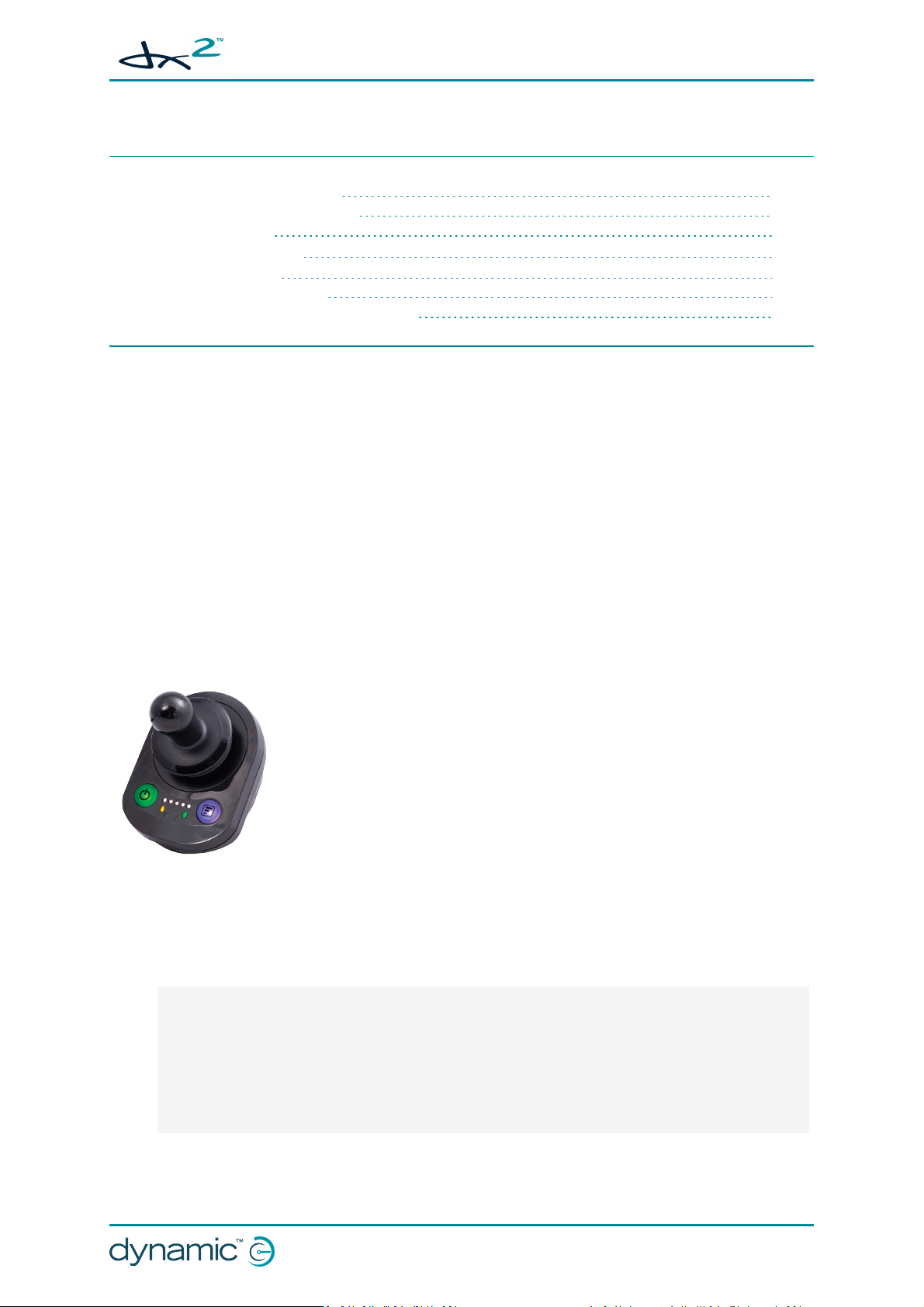
4.1.1 The DX2-RJM / DX2-RJM-LF
The DX2-RJM and DX2-RJM-LF are compact, secondary remote modules
designed to provide a simple interface for the wheelchair occupant using a
DX/DX2 system.
With a modern, low-profile design, the remote modules employ joystick
technology from the LiNX product range, and are designed to be drop-in
replacements for the DX-RJM’s. They also have several enhanced features,
including the ability to turn the system on/off and to select and operate
Figure 1: DX2-RJM and DX2RJM-LF
Low strength users will enjoy the low force joystick option with the DX2-RJM-LF, which provides
smooth control with a deflection force of just 1.1 N.
Drive and Accessory menu options.
Benefits
l Built-in power button — enables the user to easily power up or down the system
l Built-in mode button
l Simple LED indicator shows what Drive Profile is selected
l Tri-colour battery gauge
l Attendant in charge indicator
l A range of mounting orientations — standard, tray, centre-line and swing-away mounts
l Low force joystick option will improve control for those with low muscle strength
Introduction - Page 9
Page 12
GBK65701 DX2 Compact Remote Modules
Installation Manual Issue 1
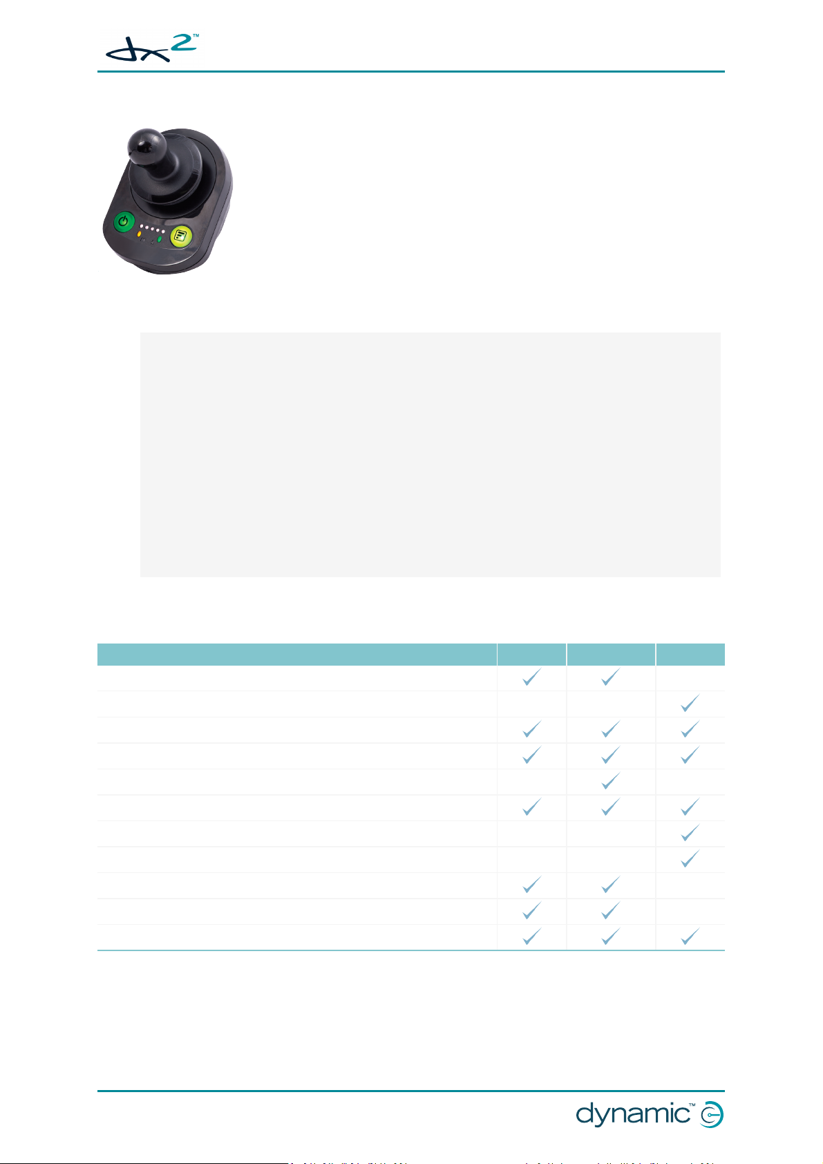
4.1.2 The DX2-ACU
The DX2-ACU, with its modern, low-profile design, is an attendant control
unit, and an ideal secondary control solution for any DX/DX2 system. It
employs joystick technology from the LiNX product range and is designed
to be a drop-in replacement for the DX-ACU’s.
The new design has several enhanced features, including a selection of
“who’s in charge” options.
Figure 2: DX2-ACU
Benefits
l Built-in power button enables the attendant to easily power up or down the system
l Mode button:
o
Short press — adjust wheelchair speed to your walking speed with digital speed control
o
Long press — easily switch control between attendant and occupant
l Range of “who’s in charge” options (first-in-first-served, attendant priority, user priority and
DX-like)
l Simple LED speed indicator showing selected speed range
l Tri-colour battery gauge
l System status and attendant in charge indication
l Control your client's comfort with the ability to select and operate actuators through the joy-
stick (with selected Master Remotes)
l Able to be mounted in a variety of orientations to suit individual chair needs
l Fully sealed case design provides improved protection against water and dust ingress
4.2 Feature comparison
Feature DX2-RJM DX2-RJM-LF DX2-ACU
Suitable for wheelchair occupants
Suitable for wheelchair attendants
Lightweight, modern design
Symmetrical design, ideal for left- and right-handed users.
Low-force joystick
Battery indicator
Speed adjustment
Speed indicator
Drive profile / accessory selection
Drive profile indicator
Attendant indicator
Page 10 - Introduction
Page 13
GBK65701 DX2 Compact Remote Modules
Installation Manual Issue 1
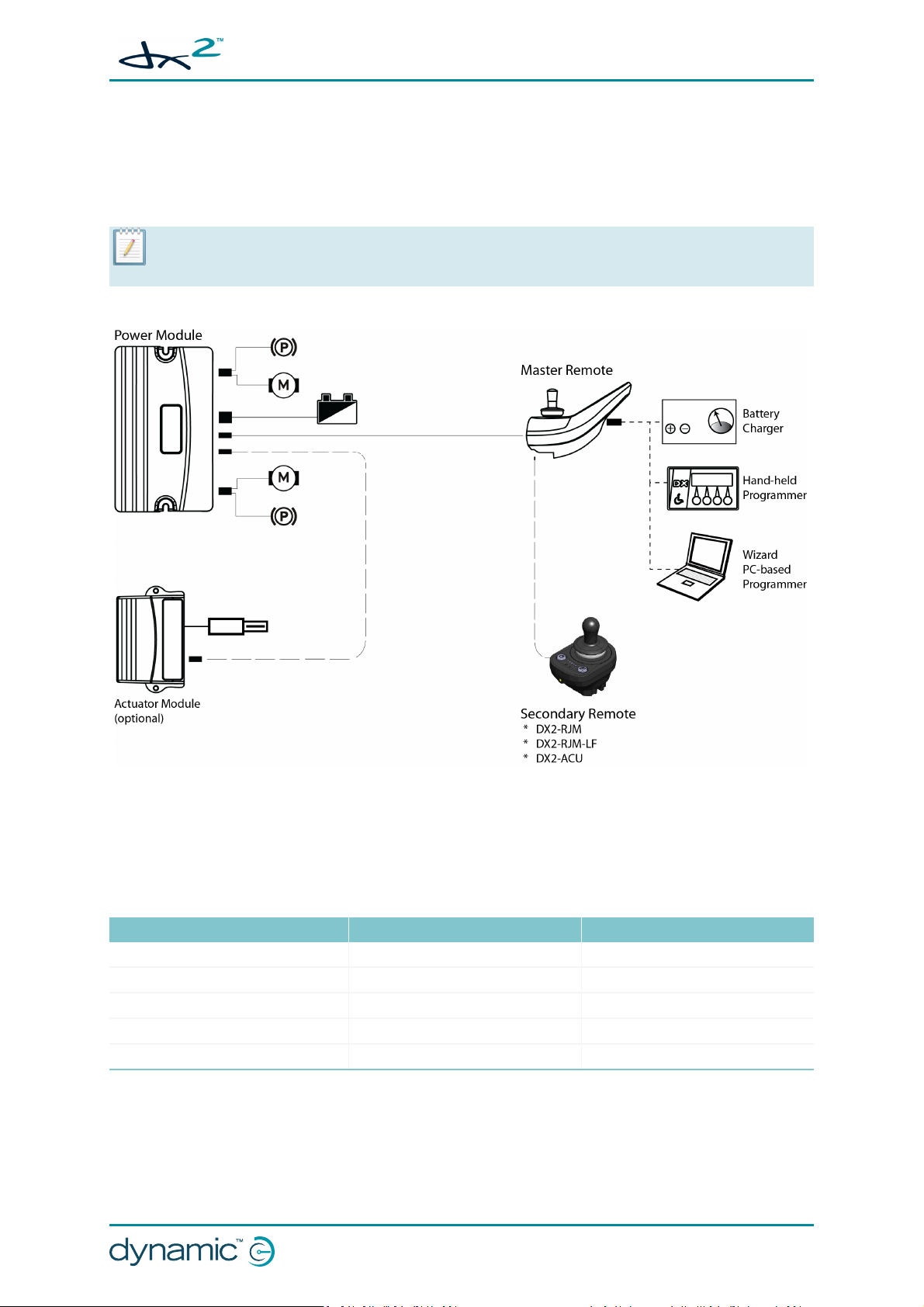
4.3 System overview
The DX2-RJM, DX2-RJM-LF and DX2-ACU operate as secondary remotes within a DX/DX2 wheelchair
control system. They connect to a master remote module via the fixed, trailing lead (DXBUS) as shown
in Figure 3: System diagram.
:
Note
Not all master remote modules are compatible with the compact remote modules - for more details, see section
4.3.2 Compatible master remote modules.
Figure 3: System diagram
4.3.1 System configurations
The DX2-RJM, DX2-RJM-LF and DX2-ACU compact remote modules can be used in the following
system configurations:
Primary Secondary Secondary
DX/DX2 Master remote DX2-ACU -
DX/DX2 Master remote DX2-RJM / DX2-RJM-LF -
DX/DX2 Master remote DX-RJM DX2-ACU
DX/DX2 Master remote DX-ACU DX2-RJM / DX2-RJM-LF
DX/DX2 Master remote DX2-ACU DX2-RJM / DX2-RJM-LF
Note that there can be only one RJM-type module in a system configuration. That is, the
configuration will support a DX2-RJM and DX2-ACU combination, or a DX2-RJM-LF and DX2-ACU
combination, but it will not support a DX2-RJM and DX2-RJM-LF combination.
Introduction - Page 11
Page 14
GBK65701 DX2 Compact Remote Modules
Installation Manual Issue 1
:
Note
Any accessory modules, such as the DSL-105 Proximity Head Control, or DX-SNP Sip and Puff, that appear as an RJM
in a DX/DX2 system, cannot be used in combination with another RJM-type module.
4.3.2 Compatible master remote modules
The DX2-RJM, DX2-RJM-LF and DX2-ACU compact remote modules will only operate with UCM II
based master remote modules. The following master remote modules are compatible with the DX2RJM, DX2-RJM-LF and DX2-ACU compact remote modules.
DX-REM24SD DX-REM34B
DX-REMG90/A/T DX-ACU3B
DX-REMG91/S DX2-REM420/1
DX-REM48/A
(see note below)
DX2-REMA/B-ACS2 DX-REM41D/E
DX2-REM550/1
Warning
The compact remotes described in this manual are to be used with selected UCM II based master remote modules
only - see table above. DONOT use with UCM I based master remote modules.
Note
All of the master remote modules listed in the table above, with the exception of DX-REM48/A, are UCM II based.
Depending on its age, the DX-REM48/A may be a UCM I type. If you are using a DX-REM48/A, ensure that it is a
UCM II type before using in a system. If you are unsure, consult your service centre.
:
:
Page 12 - Introduction
Page 15
GBK65701 DX2 Compact Remote Modules
Installation Manual Issue 1
5 Specifications
5.1 Mechanical specifications 13
5.2 Electrical specifications 13
5.1 Mechanical specifications
Parameter Value
Protection rating IPx4
Shipping weight < 400g
Min Nominal Max Units
Operating temperature range -25 - 50 °C
Storage temperature range -40 - 65 °C
Operating humidity range 0 - 90 %RH
Operating forces Min Nominal Max Units
l Joystick
o
o
l
Mode button
l
Power button
DX2-RJM / DX2-ACU
DX2-RJM-LF
-
-
- < 2.5 - N
- < 2.5 - N
1.6
1.1
-
-
N
N
5.2 Electrical specifications
Parameter Min Nominal Max Units
Operating voltage (Vbatt) 18 24 32 V
Idle current - 56 - mA@24V
Quiescent current (power off) - - 0.23 mA@24V
Specifications - Page 13
Page 16
GBK65701 DX2 Compact Remote Modules
Installation Manual Issue 1
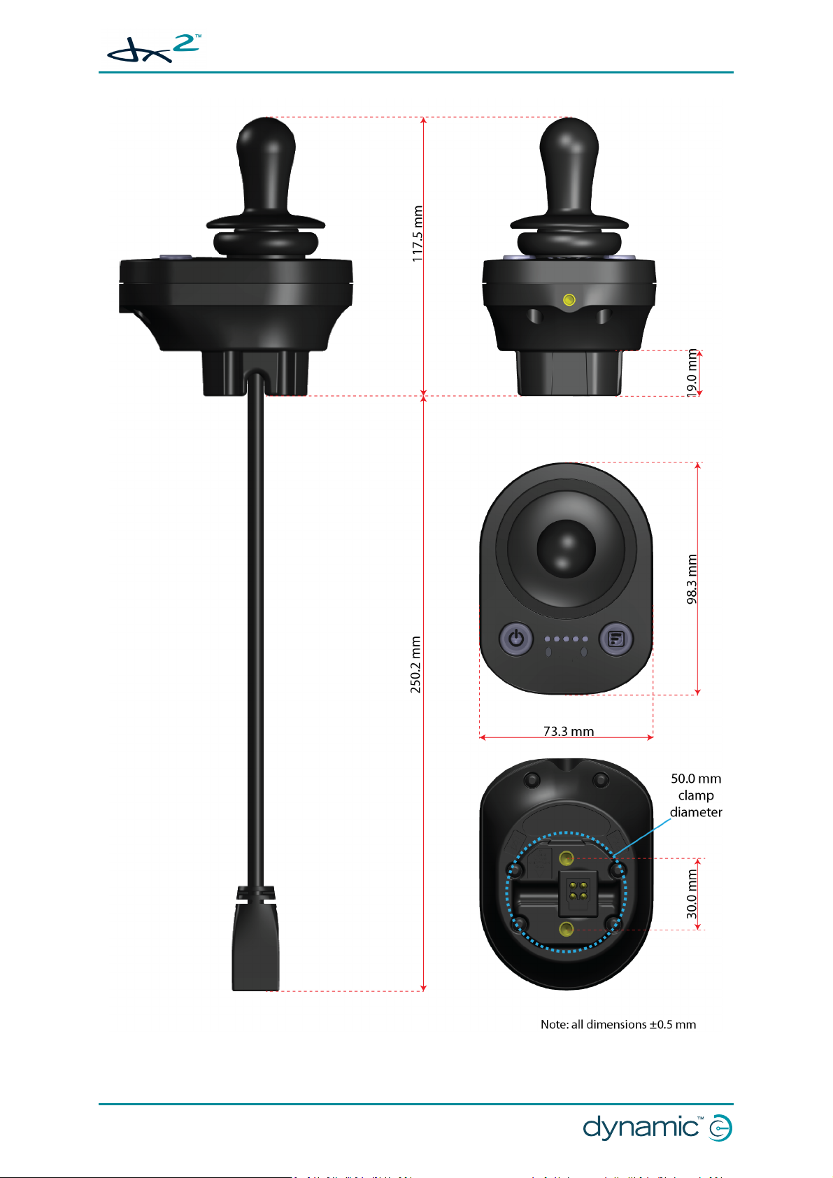
Figure 4: Dimensions - DX2-RJM, DX2-RJM-LF and DX2-ACU
Page 14 - Specifications
Page 17
GBK65701 DX2 Compact Remote Modules
Installation Manual Issue 1
6 Installation
6.1 Mounting 15
6.1.1 Cable routing options 15
6.1.2 Tray mount 16
6.1.3 Clamp mount 16
6.1.4 Plate mount 16
6.1.5 Tube mount 17
6.1.6 Drop-in mount 17
6.2 Positioning 18
6.2.1 DX2-RJM/-LF 18
6.2.2 DX2-ACU 18
6.3 Wiring 18
6.4 Programming 20
6.4.1 User profile options 20
6.4.2 System settings 20
6.1 Mounting
There are numerous options available for mounting the compact remote module, such as:
l tray mount
l clamp mount
l base plate mount
The choice will depend on the type of compact remote (DX2-RJM/-LF or DX2-ACU) being installed and
its user (wheelchair occupant or attendant): for a wheelchair occupant, the tray, clamp and base plate
mount options may be suitable; for a wheelchair attendant, the tube or drop-in mount options may
be more suitable.
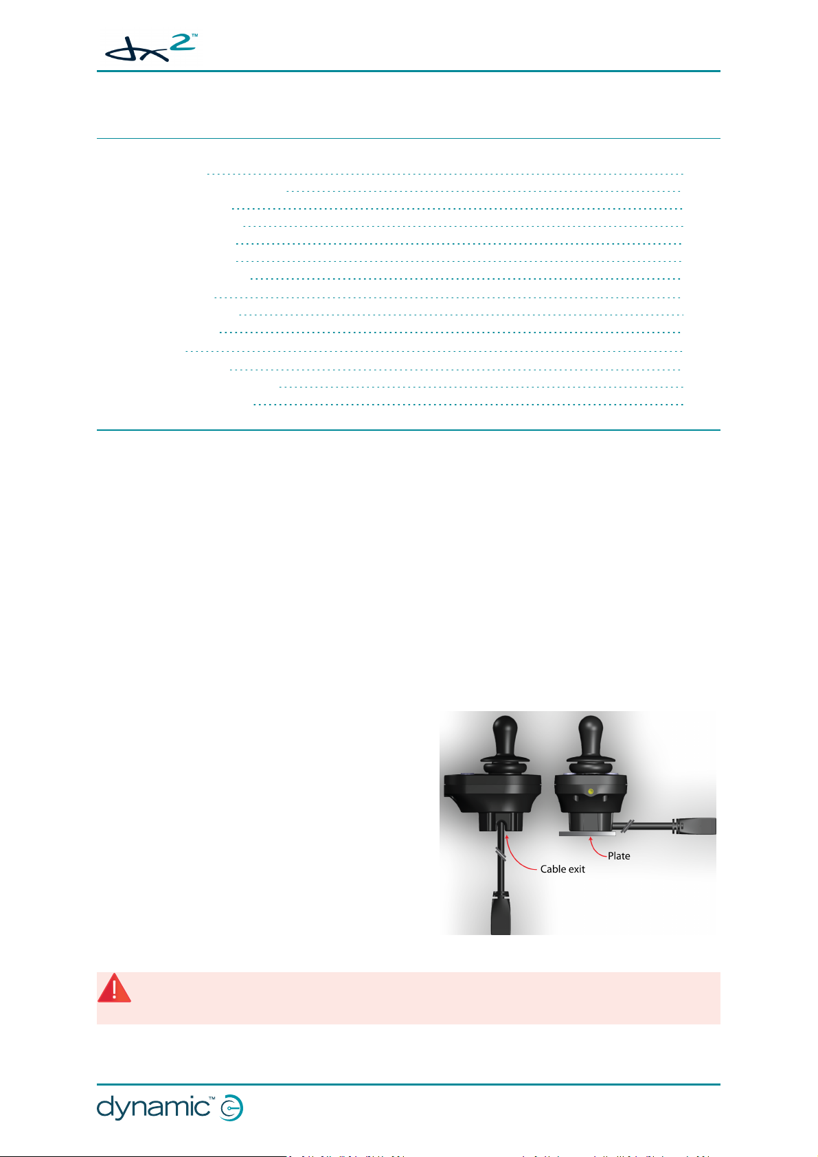
6.1.1 Cable routing options
The base of the remote module has two cable exit
recesses located on either side. These allow the bus
cable to extend from the remote at any angle between
vertical and horizontal.
For plate mounting options, this means that the cable
can be routed to the side of the remote module, and
above the plate, as shown in Figure 5.
l tube mount
l drop-in mount
Figure 5: Cable routing options
Warning
Limit to ten or fewer the number of times the compact remote module is installed on to a plate if the bus cable is
at 90° to the module; frequent flexing at this angle may damage the cable.
:
Installation - Page 15
Page 18

GBK65701 DX2 Compact Remote Modules
Installation Manual Issue 1
:
Note
The mounts shown in the following sections are suggestions only; Dynamic Controls does not manufacture or
supply the mounts. The OEM is responsible for the final design of the mount and its application.
6.1.2 Tray mount
The remote module can be mounted on to any suitable flat
surface, such as a tray, using the fixing holes underneath the
module and two M5 bolts. The maximum torque to fasten these
bolts is 3 Nm – do not exceed this rating as it may damage the
remote module.
This solution is ideal for wheelchair occupants that require the
remote module to be in a more central position, rather than the
standard placements of the left- or right-hand armrests.
Figure 6: Fi xing centres
6.1.3 Clamp mount
The compact remote has a cylindrical base which is suitable for attaching a cylindrical style clamp or
clip.
Figure 7: Clamp diameter Figure 8: Clamp mount Figure 9: Fi xing the clamp mount
6.1.4 Plate mount
The remote module can be mounted using a flat base plate (see Figure 10: Base plate example) and
two M5 bolts. The maximum torque to fasten these bolts is 3 Nm – do not exceed this rating as it may
damage the remote module.
Figure 10: Base plate example
Figure 11: Fixing the base plate
Page 16 - Installation
Page 19

6.1.5 Tube mount
Figure 12: Tube mount (from above)
The tube diameter will depend on the tube clamp
used, and also the fixing hole centres on the
remote module (30 mm). A tube with an outside
diameter of 15 - 22 mm would be suitable.
Use two M5 bolts to fasten the tube between the
clamp and the base. The maximum torque to
fasten these bolts is 3 Nm – do not exceed this
rating as it may damage the remote module.
Ensure that the DXBUS cable is not pinched when
tightening the tube clamp.
GBK65701 DX2 Compact Remote Modules
Installation Manual Issue 1
The remote module can be fixed on to a tube
using a suitable tube clamp. This solution is useful
for tubes that run perpendicular to the remote
module, as shown left.
Figure 13: Fixing the tube mount
6.1.6 Drop-in mount
The depth and shape of the base of the compact remote module allows it to be placed into a suitably
designed cradle, such as the drop-in mount shown in Figure 14.
The drop-in mount is ideal for the DX2-ACU attendant remote module, allowing an attendant to
remove and replace the module with ease, and also use the module at a comfortable, safe distance
from the wheelchair. Design the mount to prevent the remote module from falling out accidentally,
or twisting around when used in the mount. A concept drawing is shown below.
Figure 14: Concept drawing for drop-in mount
Installation - Page 17
Page 20

GBK65701 DX2 Compact Remote Modules
Installation Manual Issue 1
6.2 Positioning
6.2.1 DX2-RJM/-LF
Position the remote module such that a typical user's arm is in a natural, comfortable position.
:
Note
It is the responsibility of both the manufacturer and the dealer to determine the most appropriate installation
suitable for any single user. This includes, but is not limited to, the placement of the remote module for long term,
comfortable use.
For wheelchair occupants using the DX2-RJM or DX2-RJM-LF, the OEM manufacturer should consider
providing a hand guard at the front of the compact remote module to protect the user's hand against
crushing, such as when manoeuvring under a table.
Warning
If the wheelchair's remote module has not been fitted with a hand guard, the user should be made aware that
their hand will not be protected from crushing, when, for example, manoeuvring towards or under a table.
:
When positioning the compact remote, consider the position of the master remote module too. The
wheelchair occupant must be able to see the master remote display when the compact remote
module's display is switched off or when actuators are being used, since actuator feedback is only
displayed on the master remote, not the compact remote.
6.2.2 DX2-ACU
Do not install or place the compact remote module higher than 1.2 m from the ground.
To minimise the risk of snagging, Dynamic Controls recommends permanently fixing the compact
remote module to the rear of the wheelchair, when used as an attendant remote, in line with EN
12184:2009 8.6 Assistant control unit, push handles and handgrips.
For compact remote modules that are not permanently fixed to the wheelchair, limit the length of the
cable between the product and the back of the wheelchair to:
1. minimise the chance of the product hitting the floor, and being damaged if dropped;
2. minimise the chance of the joystick landing on the floor and deflecting, causing a runaway situation;
3. minimise the chance of snagging the cable on an external object.
The recommended total length of the bus cable, between the product and the back of the wheelchair,
must be no longer than the height above the ground that the product is normally placed. For an extra
margin of safety, reduce the cable length by a further 0.25 m.
:
Note
It is recommended that the low force compact remote module (DX2-RJM-LF) is not used as an attendant remote. If
the remote is dropped, the mass of the remote, relative to the joystick deflection force, makes a runaway more
likely than if the full deflection force joystick (DX2-ACU) is used.
6.3 Wiring
For safe and reliable operation, the installation of looms and cables must follow the basic principles of
power wiring.
Page 18 - Installation
Page 21

GBK65701 DX2 Compact Remote Modules
Installation Manual Issue 1
Cables must be secured between their connectors and any point of flexing so that flexing forces are
not transferred to the connectors.
Warning:
Route and position cables and remote modules so that they are free from physical strain, abuse or damage, such
as snagging, crushing, impacts from external objects, pinching or abrasion.
Warning
Damage to cables increases wiring impedance. A damaged cable can potentially produce localised heat, sparks or
arcing and become a source of ignition to surrounding flammable material. The installation must ensure that all
power cables, including the bus cable, are protected against damage and potential contact with flammable
materials.
:
Adequate strain relief must be provided for all cables, and the mechanical limits of the cables and
looms must not be exceeded.
Ensure that connectors and connector sockets are shielded from water splashes and water ingress.
Cables with female connectors should face horizontally or downwards. Ensure all connectors are fully
mated.
Warning
Connector pins on cables connected to the power module can still be live even when the system is off. Cables with
live pins should be connected, restrained or covered so that they are not exposed to human contact or materials
that could cause electrical shorts.
:
Make sure that the cables do not extend beyond the wheelchair to prevent them from being caught
or damaged by external objects. Take particular care on wheelchairs with movable structures such as
a seat raise.
Warning
Avoid routing the cable where it will come into continuous contact with the end user.
:
When installing the bus cable, avoid undue straining of the cable and connection points. Flexing of
the cable should be minimised wherever possible, to extend service life and minimise the risk of
accidental damage.
Warning
Use of a cable chain to support the bus cable, where the cable is subject to regular cyclic bending, is
recommended. The maximum stretch of the chain should be less than the length of the bus cable. The force
applied to flex the cable should never exceed 10 N.
Note
Appropriate life testing should be carried out to determine / confirm the expected service life and inspection and
maintenance schedule.
:
:
See also:
6.1.1 Cable routing options
Installation - Page 19
Page 22

GBK65701 DX2 Compact Remote Modules
Installation Manual Issue 1
6.4 Programming
Before using the compact remote modules, update the system's User Profile Options and System
Settings, as detailed below.
6.4.1 User profile options
In the User Profile Options section, set the Joystick Source
option to the type of remote
module for one of the available
profiles.
Figure 15: Joystick Source example
For example, in Figure 15, Joystick Source has been set to RJM in Profile 4.
:
Note
Dynamic Controls recommends that you do not select ACU for the Joystick Source parameter for profiles 1 - 5.
The ACU profile is automatically selected by the master remote module when the ACU takes control of a system. If
another profile, other than the ACU profile, is selected and the profile has been configured with the ACU as the
joystick source, then the Attendant indicator will not operate—the Attendant indicator only operates with the ACU
profile.
See also
7.1.7 Attendant indicator
:
6.4.2 System settings
Set RJM Enable to Yes if a DX2-RJM or DX2-RJM-LF is part
of the system.
Set ACU Enable to Yes if a DX2-ACU is part of the system.
Figure 16: Set RJ MEnable
See also
7 Operation
:
Page 20 - Installation
Figure 17: Set ACU Enable
Page 23

GBK65701 DX2 Compact Remote Modules
Installation Manual Issue 1
7 Operation
7.1 DX2-RJM, DX2-RJM-LF operation 21
7.1.1 The joystick 22
7.1.2 Power button and status indicator 23
7.1.3 Emergency stop 23
7.1.4 Mode button 23
7.1.5 Information display 24
7.1.6 Battery gauge indicator 25
7.1.7 Attendant indicator 26
7.1.8 Sleep mode 26
7.1.9 Lock mode 27
7.1.10 Configuration mode 27
7.2 DX2-ACU operation 29
7.2.1 The joystick 30
7.2.2 Power button and status indicator 30
7.2.3 Emergency stop 31
7.2.4 Mode button 31
7.2.5 Speed indicator 32
7.2.6 Battery gauge indicator 32
7.2.7 Attendant indicator 33
7.2.8 Sleep mode 34
7.2.9 Lock mode 34
7.2.10 Configuration mode 35
7.1 DX2-RJM, DX2-RJM-LF operation
:
Note
The following section details the operation for DX2-RJMand DX2-RJM-LF only. For a description of the DX2-ACU's
operation, see section 7.2 DX2-ACU operation .
The DX2-RJM and DX2-RJM-LF (low force joystick version)
are drop-in replacements for the DX-RJM. They are
designed to be used by the wheelchair occupant as a
secondary remote module, and connected to a DX/DX2
system via the fixed, trailing DXBUS cable.
The symmetrical design of the controller, and its trailing
lead enables the remote modules to be fitted and operated
left of the user, right of the user or anywhere in between.
The fixing holes permit a range of mounting orientations
including standard, tray, centre-line and swing-away
mounts.
Warning
Users should be aware that the surface of the remote module can potentially get hot when it is exposed to strong
sunlight for long periods.
:
Figure 18: The DX2-RJM, DX2-RJM-LF user interface
Operation - Page 21
Page 24

GBK65701 DX2 Compact Remote Modules
Installation Manual Issue 1
Figure 18 shows the main components of the DX2-RJM and DX2-RJM-LF. These are described below:
o
joystick - to control speed and direction
o
power button (with status LED) - to power up or power down the system, and
view the system's status
o
mode button - to select drive profile
o
information display - displays selected drive profile
o
battery indicator - displays battery status
o
attendant indicator - displays which controller (occupant's or attendant's) has
control of the wheelchair
Note
To operate, the DX2-RJM and DX2-RJM-LF must be connected to a DXsystem via the DXBUStrailing lead.
Warning
Do not use the compact remote module if it is worn or damaged. Worn or damaged modules should be serviced
immediately, especially if the DXBUS cable, joystick gaiter or keypad are ripped, torn or damaged.
:
7.1.1 The joystick
Warning
The compact remote modules may only be used with the authorised joystick knobs. Use of any other joystick knob
requires that the installer tests and confirms that the joystick returns to the neutral position whenever the joystick
is deflected. Tests with the device mounted horizontally and with a water soaked knob (foam knobs only) are
required if the installer judges these risks as significant.
Figure 19: The joystick
If the user moves the joystick back to the neutral position, the wheelchair will slow down and stop.
:
The joystick controls the direction and speed of the wheelchair.
When the joystick is deflected from the centre (neutral) position, the
wheelchair will move in the direction of the joystick movement.
The speed of the wheelchair is proportional to the joystick deflection, so that
the further the joystick is moved from the neutral position, the faster the
wheelchair will travel.
If the user releases the joystick from any position other than the neutral position, the joystick will
return to the neutral position and the wheelchair will slow down and stop.
The joystick can also be used to wake up the system when in sleep mode — see 7.1.8 Sleep mode.
Warning
It is the responsibility of the wheelchair manufacturer to inform the wheelchair user about the wheelchair's
stopping distances.
See also
9.1 OONAPU
7.1.8 Sleep mode
:
:
Page 22 - Operation
Page 25

GBK65701 DX2 Compact Remote Modules
Installation Manual Issue 1
7.1.2 Power button and status indicator
:
Note
In the event that the wheelchair is in a runaway situation, press the remote module's power button to perform an
EMERGENCY STOP. See section 7.1.3 Emergency stop.
The power button is on the left-hand side of the remote module, and incorporates a status indicator
that changes colour depending on the status of the system:
Off - system OFF or
sleeping
Red (flashing) - powered ON fault
Green - powered ON.
Press the power button to switch the system ON. If there is no fault with the system, the status
indicator (under the power button) will light up green.
Press the power button to switch the system OFF; the system will power down and the status
indicator will switch off.
If there is a fault with the system, the status indicator will indicate the fault with a series of red flashes
(see section 9 Diagnostics).
7.1.3 Emergency stop
If the user needs to stop the wheelchair quickly, the power button can be pressed to perform an
EMERGENCY STOP. The wheelchair will come to a halt quickly; the rate is set by the Emergency
Deceleration parameter.
Warning
Ensure that the wheelchair's settings are appropriate for both the wheelchair configuration and the user. If the
Emergency Deceleration parameter is set too high, the user can lose balance or fall out of the wheelchair when an
emergency stop is performed.
:
See also
See the DX System Manual / Master Remote manual for more information about the Emergency Deceleration
parameter.
:
7.1.4 Mode button
The mode button is on the right-hand side of the remote module and
incorporates a purple indicator that is lit continuously (except when a drive
Figure 20: The mode
button
The operation of the mode button is dependent on the type of master remote module within the
system. It can be used to:
l swap between modes (drive profile mode or accessory mode);
l step through a mode;
l step back through a mode.
The mode button reacts to two actions:
inhibit is present) while the system is powered up.
Operation - Page 23
Page 26

GBK65701 DX2 Compact Remote Modules
Installation Manual Issue 1
l a short press (less than ½ second)
l a long press (greater than ½ second)
The table below shows how the mode button operates with long and short presses for the
compatible master remote modules.
Master remote
module
DX-REM24SD Short Increments drive profile.
DX-REMG90/A/T Short Increments drive profile, and then, after the highest drive profile, it
DX-REMG91/S Short Behaviour depends on the input mode used. Typically a short press will
DX-REM48/A Short Increments drive profile. After the highest drive profile, it enters lighting
DX-REM34B
DX-REM41D/E
DX-ACU3B Short Increments drive profile. After the highest drive profile, it enters into
DX2-REM420/1
DX2-REMA/B-ACS2
DX2-REM550/1 Short This is configurable with the External Mode/Up Down parameter in Wiz-
Mode button
press
Long Scrolls through the available accessory modes.
enters accessory mode.
Long Decrements drive profile.
Long
Long Decrement profile.
Short Increments drive profile.
Long Decrements drive profile.
Long Decrements drive profile.
Short Increments drive profile.
Long Selects last actuator profile. Subsequent long presses increments actuator
Long This is configurable with the External Mode/Up Down parameter in Wiz-
increment a mode or profile and a long press will decrement in the same
way. Note: The RJM cannot be used in scanning input mode.
mode.
Note: The DX2-RJM cannot be used to enter/leave actuator profiles.
Note: The DX2-RJM cannot enter any accessory modes with these master
remote modules.
actuator profile (if an actuator module is connected) and the mode button
will not be responded to.
profile.
ard under User Options.
ard under User Options.
Function
7.1.5 Information display
Figure 21: Information display
Page 24 - Operation
The information display is a group of five LEDs that displays the
currently selected drive profile.
The LEDs light up one-by-one, from left to right, as the user scrolls
through the available drive profiles; the number of LEDs lit
corresponds to the selected drive profile.
Page 27

GBK65701 DX2 Compact Remote Modules
Installation Manual Issue 1
:
Note
Whenever a new drive profile is selected which has a different joystick source, the drive profile LEDs and the mode
button LED will flash briefly.
7.1.6 Battery gauge indicator
The battery gauge is situated below and left of the information
display. It displays the battery's state of charge if it's not being
charged or a battery charging sequence when the battery is being
charged, as described below.
Figure 22: The battery gauge indicator
:
Note
Users who find it difficult to differentiate the colours used in the battery gauge should use the master remote
module's display to determine the battery's state of charge.
7.1.6.1 Battery gauge indicator when not charging
If the battery is not being charged, the battery gauge displays the battery's state of charge with one
of three colours (green, amber and red).
The indicator is permanently lit when the battery is between full and low; when the state of charge
drops to or below the battery empty level, the indicator will flash too.
The table below shows the battery gauge indicator and the recommended actions for each state.
Indicator Battery state of charge Recommended actions
Flashing green - battery overcharged
Green - battery full. No action required.
Amber - battery half full. Consider starting return journey.
Red - battery low. Consider recharging battery soon.
Flashing red - battery empty. Recharge the battery now.
Stop charging the battery
7.1.6.2 Battery gauge indicator when charging
If the battery is being charged, the battery gauge displays the battery charging sequence. The
charging sequence, which repeats every 3.6 seconds, is a succession of:
green → amber → red → off → current state of charge → off
Each stage of the sequence is lit for 400 ms except for current state of charge, which is lit for 1.6
seconds. The current state of charge stage displays the battery level as the battery is charging: red
(empty), amber (half full) or green (full).
Operation - Page 25
Page 28

Figure 23: Battery charging sequence
7.1.7 Attendant indicator
The attendant indicator displays which controller (DX2-RJM or attendant's)
has control of the wheelchair (see note below).
If there is no attendant control module in the system, then this indicator will
Figure 24: Attendant
indicator
always be switched off.
GBK65701 DX2 Compact Remote Modules
Installation Manual Issue 1
If there is an attendant control module in the system, then this indicator will be switched off when
either of the occupant's remote modules has control of the wheelchair.
If there is an attendant control module in the system, then this indicator will be switched on (green)
when the attendant's remote module has control of the wheelchair.
:
Note
This indicator only operates with the ACU profile — the ACU profile is automatically selected by the master remote
module when the ACU takes control of a system. If another profile, other than the ACU profile, is selected and the
profile has been configured with the ACU as the joystick source, then this indicator will not operate.
Dynamic Controls recommends that the Joystick Source parameter for profiles 1 - 5 is not programmed for ACU.
See also
6.4.1 User profile options
:
7.1.8 Sleep mode
When the system enters into sleep mode, all indicators on the DX2-RJM and
DX2-RJM-LF are switched off. This minimises any distracting light when, for
Figure 25: Sleep mode
Waking a system from sleep depends on whether the remote module waking the system was the
active remote module before the system went to sleep.
instance, the occupant wants to sleep.
7.1.8.1 Waking from sleep mode with active remote module
If the remote module waking the system was the active remote module before the system went to
sleep, then the system can be woken by either:
l momentarily deflecting the joystick, or
l pressing the power button.
Page 26 - Operation
Page 29

GBK65701 DX2 Compact Remote Modules
Installation Manual Issue 1
:
Note
Set the joystick wake up parameter in Wizard to enable this functionality. The parameter name varies depending
on the remote. For example, for a DX2-REM55x, set Joystick Wake-up from Sleep parameter to Yes. Or, for a DX-
REMG91S, set the Enable Joystick Wakeup parameter to Yes.
7.1.8.2 Waking from sleep mode with inactive remote module
If the remote module waking the system was NOT the active remote module before the system went
to sleep, then the system can ONLY be woken by pressing the power button.
7.1.9 Lock mode
When a DX/DX2 system is locked, the DX2-RJM and DX2-RJM-LF user inputs and display are
deactivated. A DX/DX2 system cannot be locked or unlocked with the DX2-RJM or DX2-RJM-LF, but
the locked status can be displayed to the user when the user presses the power button. The
indication is different for DX and DX2 systems.
7.1.9.1 Locked indication in DX systems
To indicate a locked DX system, the mode button will flash (½ second on, ½ second off) when the
power button is pressed.
7.1.9.2 Locked indication in DX2 systems
To indicate a locked DX2 system, the mode button displays inhibit when the power button is pressed.
7.1.10 Configuration mode
The configuration mode is used to set the user display on or off.
The normal operation is for the user display to be on, when the system is powered up, so that the
user can see how the system is working and performing. However, there may be times, such as when
the compact remote is used as a chin control, when the user display is not required. If the display is
set to off, then nothing will be displayed on the display at any time.
The options are:
1. Display on (default setting) - all LEDs will display according to their function, when the system is
powered up.
2. Display off - all LEDs are switched offat all times.
Note:
When the display is switched off, the occupant can view wheelchair information with the master remote module.
7.1.10.1 Enter configuration mode
Configuration mode can only be entered with the following button press sequence:
[Note that the system must be powered down to begin.]
1. Press and hold the mode button.
2. Press and hold the power button until both the mode and power button indicators light up
green.
3. Release the power button as soon as the power button indicator switches off.
4. Release the mode button as soon as the mode button indicator switches off.
The battery gauge will light up with the current display setting.
Operation - Page 27
Page 30

GBK65701 DX2 Compact Remote Modules
Installation Manual Issue 1
7.1.10.2 Change display mode
To change the display mode, press the mode button to scroll through the options. The battery gauge
colour indicates the option:
Display on Display off
7.1.10.3 Exit configuration mode
To exit configuration mode, press the power button once. Alternatively, if there is no activity for 15
seconds, the remote module automatically exits from configuration mode.
The setting is saved automatically on exit.
Page 28 - Operation
Page 31

7.2 DX2-ACU operation
:
Note
The following section details the operation of the DX2-ACU only. For a description of the operation of the DX2-
RJM and DX2-RJM-LF, see section 7.1 DX2-RJM, DX2-RJM-LF operation .
The DX2-ACU (attendant control unit) enables an
attendant to take over control of a connected DX/DX2based wheelchair. It may be permanently mounted
onto a wheelchair (normally mounted at the rear) or
may be a general purpose, floating unit, plugged into
and used with a number of DX equipped chairs.
The DX2-ACU is connected into a DX/DX2 system via
the DXBUS trailing lead, and configured with the
Dynamic Wizard and HHP.
While in attendant mode, joystick control provided by
the DX2-ACU is enabled and joystick control from the
user remote module is disabled. Conversely, when in
user mode, only the joystick control on the user's
remote module is enabled and joystick control on the
DX2-ACU is disabled. In either case, any other controls
available on the user's remote module (lighting,
actuators, etc.) are fully functional.
GBK65701 DX2 Compact Remote Modules
Installation Manual Issue 1
Figure 26: The DX2-ACU user interface
Warning
When the remote module is operated while being held in the hand, be aware that it is possible for the hand to get
trapped by the trailing cable.
Warning
Users should be aware that the surface of the remote module can potentially get hot when it is exposed to strong
sunlight for long periods.
:
:
Figure 26 shows the main components of the DX2-ACU. These are described below:
o
joystick - to control speed and direction
o
power button (with status LED) - to power up or power down the system, and
view the system's status
o
mode button - to select speed, toggle who's in charge
o
speed indicator - displays selected speed
o
battery indicator - displays battery status
o
attendant indicator - displays which controller (occupant's or attendant's) has
control of the wheelchair
Note
To operate, the DX2-ACU must be connected to a DXsystem via the DXBUStrailing lead.
Warning
Do not use the compact remote module if it is worn or damaged. Worn or damaged modules should be serviced
immediately, especially if the DXBUS cable, joystick gaiter or keypad are ripped, torn or damaged.
:
Operation - Page 29
Page 32

7.2.1 The joystick
GBK65701 DX2 Compact Remote Modules
Installation Manual Issue 1
Warning
The compact remote modules may only be used with the authorised joystick knobs. Use of any other joystick knob
requires that the installer tests and confirms that the joystick returns to the neutral position whenever the joystick
is deflected. Tests with the device mounted horizontally and with a water soaked knob (foam knobs only) are
required if the installer judges these risks as significant.
:
The joystick controls the direction and speed of the wheelchair.
When the joystick is deflected from the centre (neutral) position, the
wheelchair will move in the direction of the joystick movement.
The speed of the wheelchair is proportional to the joystick deflection, so that
the further the joystick is moved from the neutral position, the faster the
Figure 27: The joystick
wheelchair will travel.
If the user moves the joystick back to the neutral position, the wheelchair will slow down and stop.
If the user releases the joystick from any position other than the neutral position, the joystick will
return to the neutral position and the wheelchair will slow down and stop.
The joystick can also be used to wake up the system when in sleep mode — see 7.2.8 Sleep mode.
Warning
It is the responsibility of the wheelchair manufacturer to inform the wheelchair user about the wheelchair's
stopping distances.
See also
9.1 OONAPU
7.2.8 Sleep mode
:
:
7.2.2 Power button and status indicator
:
Note
In the event that the wheelchair is in a runaway situation, press the remote module's power button to perform an
EMERGENCY STOP. See section 7.2.3 Emergency stop.
The power button is on the left-hand side of the remote module, and incorporates a status indicator
that changes colour depending on the status of the system:
Off - system OFF or
sleeping
Green - powered ON.
Red (flashing) - powered ON fault
Press the power button to switch the system ON. If there is no fault with the system, the status
indicator (under the power button) will light up green.
Press the power button to switch the system OFF; the system will power down and the status
indicator will switch off.
Page 30 - Operation
Page 33

GBK65701 DX2 Compact Remote Modules
Installation Manual Issue 1
If there is a fault with the system, the status indicator will indicate the fault with a series of red flashes
(see section 9 Diagnostics).
See also
7.2.10 Configuration mode
:
7.2.3 Emergency stop
If the attendant needs to stop the wheelchair quickly, the power button can be pressed to perform
an EMERGENCY STOP. The wheelchair will come to a halt quickly; the rate is set by the Emergency
Deceleration parameter.
Warning
Ensure that the wheelchair's settings are appropriate for both the wheelchair configuration and the user. If the
Emergency Deceleration parameter is set too high, the user can lose balance or fall out of the wheelchair when an
emergency stop is performed.
See also
See the DX System Manual / Master Remote manual for more information about the Emergency Deceleration
parameter.
:
:
7.2.4 Mode button
The mode button is on the right-hand side of the remote module and
incorporates a yellow indicator that is lit continuously (except when a drive
Figure 28: The mode
button
inhibit is present) while the system is powered up.
Depending on the length of time that the button is pressed (short or long), the mode button is used
to:
l change the speed setting, or
l toggle between who's in charge (occupant or attendant remote module) .
7.2.4.1 Change speed setting
A short press (less than ½ second) on the mode button changes the wheelchair's speed setting.
Each short press increments the speed by 20 %, between 20 % and 100 % of the maximum speed that
has been set for the Attendant Drive profile. After reaching 100 %, the speed setting will roll around to
20 %.
The speed is displayed on the speed indicator as shown in 7.2.5 Speed indicator.
:
Note
The speed setting is recorded when the system is powered down so that it will resume the same speed setting on
power up. If for any reason that the speed setting is not available on power up, or becomes corrupted, then the
speed setting will default to 40 % of the speed that has been set for the Attendant Drive profile.
7.2.4.2 Change who's in charge
A long press (greater than ½ second) on the mode button toggles the control between the occupant's
remote module, and the attendant's.
Operation - Page 31
Page 34

GBK65701 DX2 Compact Remote Modules
Installation Manual Issue 1
If the occupant's remote module has control, a long press will switch the control to the DX2-ACU, and
the Attendant indicator will light up to show that the DX2-ACU has control.
If the DX2-ACU has control, a long press will switch the control to the occupant's remote module, and
the Attendant indicator will switch off to show that the DX2-ACU does not have control.
See also
7.2.7 Attendant indicator
7.2.10 Configuration mode
:
7.2.5 Speed indicator
The speed indicator is a group of five LEDs that displays the currently
selected speed. The LEDs light up one-by-one, from left to right, as
the speed is incremented with the mode button (see 7.2.4 Mode
button).
Figure 29: Speed indicator (showing
60% speed)
:
Note
During a drive inhibit, the speed indicator is switched off.
Each LED represents 20 % of the maximum programmed speed of the Attendant Drive profile. The
LEDon the left-hand side of the indicator represents the lowest speed (20 %). The LEDon the righthand side represents the highest speed (100 %).
:
Note
The speed setting is recorded when the system is powered down so that it will resume the same speed setting on
power up. If for any reason that the speed setting is not available on power up, or becomes corrupted, then the
speed setting will default to 40 % of the speed that has been set for the Attendant Drive profile.
7.2.6 Battery gauge indicator
The battery gauge is situated below and left of the speed indicator. It displays the battery's state of charge if it's not being
charged or a battery charging sequence when the battery is being
charged, as described below.
Figure 30: The battery gauge indicator
:
Note
Users who find it difficult to differentiate the colours used in the battery gauge should use the master remote
module's display to determine the battery's state of charge.
7.2.6.1 Battery gauge indicator when not charging
If the battery is not being charged, the battery gauge displays the battery's state of charge with one
of three colours (green, amber and red).
The indicator is permanently lit when the battery is between full and low; when the state of charge
drops to or below the battery empty level, the indicator will flash too.
Page 32 - Operation
Page 35

GBK65701 DX2 Compact Remote Modules
Installation Manual Issue 1
The table below shows the battery gauge indicator and the recommended actions for each state.
Indicator Battery state of charge Recommended actions
Flashing green - battery overcharged
Green - battery full. No action required.
Amber - battery half full. Consider starting return journey.
Red - battery low. Consider recharging battery soon.
Flashing red - battery empty. Recharge the battery now.
Stop charging the battery
7.2.6.2 Battery gauge indicator when charging
If the battery is being charged, the battery gauge displays the battery charging sequence. The
charging sequence, which repeats every 3.6 seconds, is a succession of:
green → amber → red → off → current state of charge → off
Each stage of the sequence is lit for 400 ms except for current state of charge, which is lit for 1.6
seconds. The current state of charge stage displays the battery level as the battery is charging: red
(empty), amber (half full) or green (full).
Figure 31: Battery charging sequence
7.2.7 Attendant indicator
The attendant indicator displays which remote module (DX2-ACU or
occupant's) has control of the wheelchair.
If the occupant's remote module has control of the system, the indicator will
Figure 32: Attendant
indicator
be off. If the DX2-ACU remote module has control of the system, the
indicator will be on (green).
:
Note
This indicator only operates with the ACU profile — the ACU profile is automatically selected by the master remote
module when the ACU takes control of a system. If another profile, other than the ACU profile, is selected and the
profile has been configured with the ACU as the joystick source, then this indicator will not operate.
Dynamic Controls recommends that the Joystick Source parameter for profiles 1 - 5 is not programmed for ACU.
Operation - Page 33
Page 36

GBK65701 DX2 Compact Remote Modules
Installation Manual Issue 1
See also
6.4.1 User profile options
:
The system that has control is determined by the configuration mode setting and the mode button:
1. on powering up, the remote module that is initially in charge of the system is determined by
the configuration mode setting;
2. after powering up, a long press on the mode button changes which controller is in charge.
See also
7.2.4 Mode button
7.2.10 Configuration mode
:
7.2.8 Sleep mode
When the system enters into sleep mode, and if the DX2-ACU is the active
remote before entering sleep mode, all indicators on the DX2-ACU are
Figure 33: Sleep mode
Waking a system from sleep depends on whether the remote module waking the system was the
active remote module before the system went to sleep.
switched off except the battery gauge indicator. If the DX2-ACU is not the
active remote before entering sleep mode, all indicators on the DX2-ACU are
switched off, including the battery gauge indicator.
7.2.8.1 Waking from sleep mode with active remote module
If the remote module waking the system was the active remote module before the system went to
sleep, then the system can be woken by either:
l momentarily deflecting the joystick, or
l pressing the power button.
:
Note
Set the joystick wake up parameter in Wizard to enable this functionality. The parameter name varies depending
on the master remote. For example, for a DX2-REM55x, set Joystick Wake-up from Sleep parameter to Yes. Or, for
a DX-REMG91S, set the Enable Joystick Wakeup parameter to Yes.
7.2.8.2 Waking from sleep mode with inactive remote module
If the remote module waking the system was NOT the active remote module before the system went
to sleep, then the system can be woken ONLY by pressing the power button.
7.2.9 Lock mode
When a DX/DX2 system is locked, the DX2-ACU inputs and display are deactivated. A DX/DX2 system
cannot be locked or unlocked with the DX2-ACU, but the locked status can be displayed to the
attendant when the attendant presses the power button. The indication is different for DX and DX2
systems.
7.2.9.1 Locked indication in DX systems
To indicate a locked DX system, the mode button will flash (½ second on, ½ second off) when the
power button is pressed.
7.2.9.2 Locked indication in DX2 systems
To indicate a locked DX2 system, the mode button displays inhibit when the power button is pressed.
Page 34 - Operation
Page 37

GBK65701 DX2 Compact Remote Modules
Installation Manual Issue 1
7.2.10 Configuration mode
The configuration mode sets which remote module has the initial control of the system at power up.
The options are:
1. First in (default setting) - the remote module that powers the system up has control
2. Always user - no matter which remote module powers up the system, the wheelchair occupant will always have initial control
3. Always attendant - no matter which remote module powers up the system, the attendant will
always have initial control
4. DX-like (last out) - the remote module that has control before powering down resumes control
on power up.
:
Note
The settings in configuration mode are only used when powering up. After a system is powered up, control of a
system can be set with the mode button.
See also
7.2.4 Mode button
7.2.7 Attendant indicator
:
7.2.10.1 Enter configuration mode
Configuration mode can only be entered with the following button press sequence:
[Note that the system must be powered down to begin.]
1. Press and hold the mode button.
2. Press and hold the power button until both the the mode and power button indicators light
up green.
3. Release the power button as soon as the power button indicator switches off.
4. Release the mode button as soon as the mode button indicator switches off.
The battery gauge will light up with the current who's in charge setting.
7.2.10.2 Change who's in charge at start-up
To change who's in charge at start up, press the mode button one or more times to scroll through the
options. The battery gauge colour changes for the four options:
Amber - DX-like Red - always occupant
Blue - first in Green - always attendant
7.2.10.3 Exit configuration mode
To exit configuration mode, press the power button once. Alternatively, if there is no activity for 15
seconds, the remote module automatically exits from configuration mode.
The setting is saved automatically on exit.
Operation - Page 35
Page 38

GBK65701 DX2 Compact Remote Modules
Installation Manual Issue 1
Page 36
Page 39

GBK65701 DX2 Compact Remote Modules
Installation Manual Issue 1
8 Testing
8.1 Before testing 37
8.2 Testing the DX2-RJM / DX2-RJM-LF 37
8.2.1 Power button 37
8.2.2 User interface 38
8.2.3 Mode button 38
8.2.4 Joystick 38
8.2.5 Emergency stop 38
8.2.6 OONAPU 38
8.2.7 Wake up from sleep mode 38
8.3 Testing the DX2-ACU 39
8.3.1 Power button 39
8.3.2 User interface 39
8.3.3 Mode button 39
8.3.4 Joystick 39
8.3.5 Emergency stop 39
8.3.6 OONAPU 39
8.3.7 Wake up from sleep mode 40
The installation must be fully tested after all modules and cables have been installed. The testing
procedure is detailed in the DX System Manual (section 8 Testing), which must be read in conjunction
with this and other DX/DX2 module manuals.
Warning
Do not connect the battery positive (B+) terminal of the battery to the DX2 system until the wheelchair is lifted off
the ground. To prevent the risk of injury, Dynamic Controls recommends the use of a lifting device when lifting the
wheelchair off the ground.
:
8.1 Before testing
Check that all cables and modules in the system are connected correctly. Check especially that the
polarities of the batteries, the motors and the park brakes are connected correctly and that the
polarities are not swapped.
To prevent the wheelchair from suddenly driving away when you turn it on, put blocks under the
wheelchair frame to lift the wheels off the ground. Check that the wheels can turn freely.
Make the final connection to the battery positive (B+) terminal and close the circuit breakers.
Turn on the DX2 system with the power button on the master remote module and program the DX2
system for the appropriate wheelchair application.
Turn off the DX2 system with the power button.
8.2 Testing the DX2-RJM / DX2-RJM-LF
8.2.1 Power button
l Test that the system powers up and down correctly with the power button. For more infor-
mation on the power button, see 7.1.2 Power button and status indicator.
Test - Page 37
Page 40

GBK65701 DX2 Compact Remote Modules
Installation Manual Issue 1
8.2.2 User interface
l Power up the system and verify that the information display is operating correctly and that
there are no faults. For more information on the information display, see 7.1.5 Information display. For more information on fault indication, see 9 Diagnostics.
l Verify the battery gauge indicator is operating correctly. For more information on the battery
gauge indicator, see 7.1.6 Battery gauge indicator.
l Verify the attendant indicator is operating correctly - only if an ACU is part of the system. For
more information on the attendant indicator, see 7.1.7 Attendant indicator.
8.2.3 Mode button
l Press the mode button (using a combination of short and long presses) to change the drive pro-
file and access accessories (if fitted). For more information on the mode button, see 7.1.4
Mode button.
l Check that the mode is displayed correctly on the information display.
8.2.4 Joystick
l Drive the wheelchair in all directions and at all speeds. Ensure that the wheelchair responds to
the drive commands as programmed. For more information on the joystick, see 7.1.1 The joystick.
l Change the drive profile and drive the wheelchair in all directions and at all speeds. Ensure that
the wheelchair responds to the drive commands as programmed.
l If accessories are fitted, select an accessory with the mode button and operate the accessory
with the joystick.
8.2.5 Emergency stop
l Test the emergency stop feature by pressing the power button while driving the wheelchair.
For more information on the emergency stop feature, see 7.1.3 Emergency stop.
Warning
This procedure can be dangerous. Dynamic Controls recommends the use of a seatbelt to prevent the tester from
slipping out of the seat.
:
8.2.6 OONAPU
l Test the OONAPU feature by powering up the wheelchair with the joystick out of the neutral
(centre) position. An OONAPU warning will be displayed and the wheelchair will not drive.
l Continue the test with the joystick out of the neutral (centre) position for more than five sec-
onds - the OONAPU warning will change to an OONAPU fault.
:
Note
Ensure that the DX2-RJM or DX2-RJM-LF is set as the active module for this test.
Ensure that the parameter Disable OONAPUFaults is set to No.
For more information on the OONAPU feature, see 9.1 OONAPU.
8.2.7 Wake up from sleep mode
l Test the wake up feature when a system is asleep by one or both of the following:
o
momentarily deflecting the joystick. Note: this is only effective if the remote module waking the system was the active remote module before the system went to sleep, and the
Page 38 - Test
Page 41

GBK65701 DX2 Compact Remote Modules
Installation Manual Issue 1
system is configured to wake up from sleep with the joystick;
o
momentarily pressing the power button.
For more information on waking up from sleep, see 7.1.8 Sleep mode.
8.3 Testing the DX2-ACU
8.3.1 Power button
l Press the power button a few times to test that the system powers up and down correctly. For
more information on the power button, see 7.2.2 Power button and status indicator.
8.3.2 User interface
l Power up the system and verify that the speed indicator is operating correctly and that there
are no faults. For more information on the speed indicator, see 7.2.5 Speed indicator. For
more information on fault indication, see 9 Diagnostics.
l Verify the battery indicator is operating correctly. For more information on the battery gauge
indicator, see 7.2.6 Battery gauge indicator.
l Verify the attendant indicator is operating correctly. For more information on the attendant
indicator, see 7.2.7 Attendant indicator.
8.3.3 Mode button
l Press the mode button (using short presses) to change the driving speed.
l Check that the speed is displayed correctly on the information display.
l Press the mode button (using long presses) to toggle between who's in charge (occupant or
attendant remote module).
l Check that the attendant indicator displays correctly.
For more information on the mode button, see 7.2.4 Mode button.
8.3.4 Joystick
l Drive the wheelchair in all directions and at all speeds. Ensure that the wheelchair responds to
the drive commands as programmed.
For more information on the joystick, see 7.2.1 The joystick.
8.3.5 Emergency stop
l Test the emergency stop feature by pressing the power button while driving the wheelchair.
Warning
This procedure can be dangerous. Dynamic Controls recommends the use of a seatbelt to prevent the tester from
slipping out of the seat if the test is performed from the seat.
:
For more information on the emergency stop feature, see 7.2.3 Emergency stop.
8.3.6 OONAPU
l Test the OONAPU feature by powering up the wheelchair with the joystick out of the neutral
(centre) position. An OONAPU warning will be displayed (see OONAPU) and the wheelchair will
not drive.
Test - Page 39
Page 42

GBK65701 DX2 Compact Remote Modules
Installation Manual Issue 1
:
Note
Ensure that the DX2-ACU is set as the active module for this test.
For more information on OONAPU, see 9.1 OONAPU.
8.3.7 Wake up from sleep mode
l Test the wake up feature when a system is asleep by one or both of the following:
o
momentarily deflecting the joystick. Note: this is only effective if the remote module waking the system was the active remote module before the system went to sleep, and the
system is configured to wake up from sleep with the joystick;
o
momentarily pressing the power button.
For more information on waking up from sleep, see 7.2.8 Sleep mode.
Page 40 - Test
Page 43

GBK65701 DX2 Compact Remote Modules
Installation Manual Issue 1
9 Diagnostics
9.1 OONAPU 41
9.2 Drive inhibit indication 41
9.3 Fault indication 42
9.4 Dealing with compact remote module faults 42
9.1 OONAPU
OONAPU (“Out Of Neutral At Power Up”) is a safety feature that
prevents accidental movement of the wheelchair, either when powering
up, or when the wheelchair comes out of an inhibit state.
OONAPU warning
If the system is powered on (or comes out of an inhibit state) while the
joystick is not in the centre position, an OONAPU warning is displayed.
Figure 34: OONAPU sequence
During an OONAPU warning, the information display LEDs will flash continually (all on, followed by all
off) to alert the user, and the wheelchair will not drive. If the joystick is returned to the centre position
within five seconds, the warning will clear and the wheelchair will drive normally.
OONAPU fault
However, if the joystick remains out of neutral for longer than five seconds, an OONAPU fault will
occur (see note below); the fault is displayed by the status indicator flashing red, and the wheelchair
will not drive. To clear the fault, return the joystick to the neutral position and power the unit off and
then on again.
:
Note
An OONAPU fault will not be displayed if the Wizard parameter Disable OONAPUFaults is set to Yes.
An OONAPU fault will not occur if the active remote module is a DX2-ACU. Instead, if the DX2-ACU's joystick
remains out of neutral for longer than five seconds, the OONAPU warning will continue to be displayed.
9.2 Drive inhibit indication
When a wheelchair is in a drive inhibit state, the information display
switches off, and the mode button flashes at a rate of on for ½ second,
off for ½ second.
This sequence continues for the duration of the drive inhibit.
:
Note
Apart from the information display and mode button, the drive inhibit indication described above does not affect
any other indicators - all other indicators will continue to operate as normal.
Figure 35: Dri ve inhibit indication
(RJM top, ACU bottom)
Diagnostics - Page 41
Page 44

GBK65701 DX2 Compact Remote Modules
Installation Manual Issue 1
9.3 Fault indication
When a fault occurs, a flash code is displayed on both the master remote module and the compact
remote module. A flash code, which is displayed on the status indicator, is a number of flashes
separated by a 1.6 second gap; the number of flashes depends on the fault. For example, one flash
represents flash code one; two flashes represents flash code two, and so on.
:
Note
Faults that affect the safety of the wheelchair will cause the wheelchair to stop, while less critical ones will be
indicated but allow the wheelchair to continue driving. Some faults will automatically clear when the fault
condition is removed (non-latched) while others are latched and must be cleared by turning the controller off,
waiting five seconds, then turning the system on again.
Faults are categorised according to their source — that is, there are local faults (those that relate to
the compact remote module), and there are system faults (those that relate to one or more system
modules). Local faults take priority with the compact remote module and so local faults will be
displayed on the compact remote module instead of system faults if both local and system faults
occur at the same time.
When there is a local fault, the power button will flash red. All other indicators will be switched off. It is
possible that the rest of the system might not indicate a fault. All local faults (faults with the compact
remote module) are displayed as:
Flash Code 1: DX Module Fault
When there is a system fault, the power button will flash red. All other indicators will continue to
operate according to their role. The rest of the system will indicate the same fault or a related flash
code. System faults are displayed according to the flash codes described in the DX System Manual.
See also
For a full list of flash codes and more information regarding system faults, refer to the DX System Manual.
:
9.4 Dealing with compact remote module faults
1. If the compact remote module does not react to a command:
l Check that the module is not in sleep mode (see 7.1.9 Lock mode 7.1.8 Sleep mode or
7.2.8 Sleep mode).
l Check that the module is not in locked mode (see 7.1.9 Lock mode or 7.2.9 Lock mode).
2. If there is no power to the compact remote module:
l Check the DXBUS connector is mated correctly.
l Replace the DXBUS extension cable (if fitted).
l Replace the compact remote module.
3. For all flash code 1 faults:
l Check the DXBUS connector is mated correctly.
l Check the profile setting:
o
If the Joystick Source parameter (see 6.4.1 User profile options) of a pro-
grammable profile has been set up for a compact remote module (either RJM or
ACU), and the compact remote module cannot be seen by the system when operating in the profile, a flash code 1 will be displayed.
Page 42 - Diagnostics
Page 45

GBK65701 DX2 Compact Remote Modules
Installation Manual Issue 1
l Replace the DXBUS extension cable (if fitted).
l Replace the compact remote module.
:
Note
As it is commonplace for attendant control units to be disconnected while the wheelchair is powered up, if a DX2ACU is disconnected while the wheelchair is powered up, and the Joystick Source parameter of any of the
programmable profiles has not been set up for an ACU, then no flash code will be displayed.
Furthermore, if the DX2-ACU is disconnected when a system is operating in the ACU profile, then the system will
revert to the last selected profile and no fault will be displayed.
Diagnostics - Page 43
Page 46

GBK65701 DX2 Compact Remote Modules
Installation Manual Issue 1
Page 44
Page 47

GBK65701 DX2 Compact Remote Modules
Installation Manual Issue 1
10 Appendices
10.1 Parts list 45
10.2 Intended use and regulatory statement 45
10.2.1 Intended use DX2-RJM and DX2-RJM-LF 45
10.2.2 Intended use DX2-ACU 46
10.2.3 Device classification 46
10.2.4 Compliance and conformance with standards 46
10.3 Service life 46
10.4 Maintenance 46
10.5 Warranty 47
10.6 Safety and misuse warnings 47
10.6.1 Warnings to be included in the user manual 47
10.6.2 Service and configuration warnings 48
10.7 Electromagnetic compatibility 49
10.7.1 Minimising emissions 49
10.8 Environmental statement 49
10.9 Symbols and labelling 49
10.9.1 Product label 49
10.9.2 Other symbols and labels 50
10.9.3 Serial number and date of manufacture 50
10.1 Parts list
Description Part number
DX2 Remote Joystick Module (RJM) DX2-RJM
DX2 RJM with low force joystick DX2-RJM-LF
DX2 Attendant Control Unit (ACU) DX2-ACU
10.2 Intended use and regulatory statement
10.2.1 Intended use DX2-RJM and DX2-RJM-LF
The DX2 Remote Joystick Modules, DX2-RJM and DX2-RJM-LF, are components of the DX/DX2
System, intended to allow powered wheelchair users to interact with the System.The DX2 Remote
Joystick Modules allow control of drive functions, as well as operation of associated modules and
compatible third-party equipment, as configured and connected within the DX/DX2 System. Control
may extend to all features provided by the DX/DX2 System, or be limited by configuration for the
particular user.
The DX2 Remote Joystick Modules are not intended for users who cannot differentiate colours to
accurately determine the state of charge of the battery, where the DX2 Remote Joystick Module
battery gauge is the sole means of making this assessment.
A DX/DX2 Master Remote must be installed to provide visual feedback about the system state if the
information displayed on the DX2 Remote Joystick Module is insufficient for the user.
When used as a chin control, the DX2 Remote Joystick Modules are restricted to using the GPL55470
DLX-REM050-A Joystick Knob.
Appendices - Page 45
Page 48

GBK65701 DX2 Compact Remote Modules
Installation Manual Issue 1
10.2.2 Intended use DX2-ACU
The DX2 Attendant Control Unit, DX2-ACU, is a component of the DX/DX2 System, intended to allow
attendants to interact with the System. The DX2-ACU allows the attendant to take control of drive
function, as configured and connected within the DX/DX2 System.
The DX2-ACU is not intended for use by users who cannot differentiate colours to accurately
determine the state of charge of the battery, where the DX2-ACU battery gauge is the sole means of
making this assessment.
10.2.3 Device classification
Europe
The DX2 compact remote modules DX2-RJM, DX2-RJM-LF and DX2-ACU are components
of a Class I medical device as detailed in the Council Directive 93/42/EEC concerning
Medical Devices.
USA
The DX2 compact remote modules DX2-RJM, DX2-RJM-LF and DX2-ACU are components
of a Class II medical device (Powered Wheelchair) as detailed in 21 CFR § 890.3860.
10.2.4 Compliance and conformance with standards
In accordance with the device classification, the DX2 compact remote module is designed to enable
the wheelchair manufacturer to comply with the relevant requirements of the European Medical
Device Directive 93/42/EEC and 21 CFR § 820.30.
The DX2 compact remote module has been designed such that the combination of the wheelchair
and controller, along with accessories as applicable, complies with the Essential Requirements of the
MDD by adopting relevant clauses of harmonised standards EN12184 and EN12182, and relevant
parts of the FDA Consensus standard ANSI / RESNA WC-2:2009 for performance.
10.3 Service life
If the product has not been abused and all maintenance instructions as described in the maintenance
section have been properly followed, the expected service life (i.e. minimum serviceable life
expectancy) of the product is five (5) years. After this period, product reliability can no longer be
guaranteed and Dynamic Controls recommends the product is replaced for safety reasons. Dynamic
Controls accepts no responsibility/liability for product failure if the product is continued to be used
after the expected service life period has expired.
It is the OEM's responsibility to state the expected service life, as well as the inspection and
maintenance schedules for all modules and cables, including the DX communications bus loom.
10.4 Maintenance
The following instructions must be passed on to the operator before use of the product:
l Keep all Dynamic Controls electronic components free of dust, dirt and liquids. To clean the
product, use a cloth dampened with warm soapy water. Do not use chemicals, solvents or abrasive cleaners, as this may cause damage to the product.
l Once a month, check all vehicle components for loose, damaged or corroded components,
such as connectors, terminals or cables. Ensure that all connectors are fully mated. Restrain all
Page 46 - Appendices
Page 49

GBK65701 DX2 Compact Remote Modules
Installation Manual Issue 1
cables to protect them from damage. Replace damaged components. Check for and remove
any foreign objects or material.
l Every 6 months, test all switchable functions on the Dynamic Controls electronics system to
ensure they function correctly.
Warning
There are no user-serviceable parts in any Dynamic Controls electronic component. Do not attempt to open any
case or undertake any repairs, else warranty will be voided and the safety of the system may be compromised.
Warning
If any component is damaged in any way, or if internal damage may have occurred (for example by being dropped),
have it checked by qualified personnel before operating.
Where any doubt exists, consult your nearest service centre or agent.
:
:
10.5 Warranty
All equipment supplied by Dynamic Controls is warranted by the company to be free from faulty
workmanship or materials. If any defect is found within the warranty period, the company will repair
or, at its discretion, replace the equipment without charge for materials or labour.
This warranty is subject to the provisions that the equipment:
l has been correctly installed;
l has been thoroughly checked upon completion of installation, and all programmable options
correctly adjusted for safe operation prior to use;
l has been used solely in accordance with this manual and all other manuals of the Dynamic Con-
trols electronic components that are used on the wheelchair;
l has been properly connected to a suitable power supply in accordance with this manual;
l has not been subjected to misuse or accident, or been modified or repaired by any unauthor-
ised personnel;
l has been used solely for the driving of electrically powered mobility wheelchairs in accordance
with the intended use and the recommendations of the wheelchair manufacturer;
l has not been connected to third party devices without the specific approval of Dynamic Con-
trols.
10.6 Safety and misuse warnings
10.6.1 Warnings to be included in the user manual
The DX2-RJM, DX2-RJM-LF and DX2-ACU remote modules are part of the DX System and therefore all
safety and misuse warnings that appear in the DX System Manual apply to the DX2-RJM, DX2-RJM-LF
and DX2-ACU remote modules — see the Safety and Misuse warnings in the DX System Manual
appendices.
In addition, the following warnings and advice must be passed on to the end user before use of the
product.
l In the case of an emergency while the vehicle is driving, press the power button to perform an
emergency stop and turn the controller off.
l If there is a risk of collision with a person or object in close proximity, use the joystick and/or
speed selector to reduce the speed of the wheelchair.
Appendices - Page 47
Page 50

GBK65701 DX2 Compact Remote Modules
Installation Manual Issue 1
l Make sure that the battery charger that is used with the vehicle has a drive inhibit function
that is correctly connected for use with the controller. If you are not sure, ask your dealer or
vehicle manufacturer.
l Users should be aware that the surface of the remote module can potentially get hot when
exposed to strong sunlight for long periods.
l If the wheelchair's remote module has not been fitted with a hand guard, the user should be
made aware that their hand will not be protected from crushing, when, for example, manoeuvring towards or under a table.
l Users should be informed of the battery chargers to be used with the controller and warn
against using battery chargers of higher current ratings.
l The users should be aware of the wheelchair's stopping distances.
10.6.2 Service and configuration warnings
The following warnings are applicable to the installation technician and the dealer or the therapist
who supplies the vehicle to the end user.
l It is the responsibility of the installer to make sure that accessories and cables of the vehicle do
not interfere with the operation of the controller.
l Do not use the vehicle frame as the earth return. Any electrical low-resistance connection to
the frame is a safety risk and is not allowed by international safety standards.
l To protect the wheelchair wiring from over-currents while charging, battery chargers must be
able to reduce their current output when electrically shorted.
l If the vehicle loses electric power, it is important that an attendant is able to move the vehicle
easily.
l After you have completed the installation, check it thoroughly. Correctly adjust all pro-
grammable options before the vehicle is used.
l After you have configured the vehicle, check to make sure that the vehicle performs to the spec-
ifications entered in the programming procedure. If the vehicle does not perform to specifications, reprogram it. Repeat this procedure until the vehicle performs to specifications. If
the desired operation cannot be reached, contact your service agent.
l The dealer, therapist or other agent who supplies the vehicle to the end user has the respon-
sibility to make sure that the vehicle is correctly configured for the needs of that user.
l For each individual user, the vehicle set-up and configuration should take into consideration
his or her:
o
technical knowledge, experience and education, and
o
medical and physical condition, including the level of disability and capability (where
applicable).
l It is the responsibility of the OEM and installer to make sure that the maximum driving speed
of the vehicle is limited as appropriate when the vehicle is in a mechanically unstable position,
for example when the seat is raised.
l It is the responsibility of the therapist/installer to minimise any risk of use error, including
those arising from ergonomic features and/or the environment in which the device is intended
to be used.
l Prior to handing over the vehicle, make sure that users are fully able to operate the product by
giving them appropriate training on functionality and safety features, and having them test
drive the vehicle in a safe area in the presence of their agent.
l The controller can cause the vehicle to come to a sudden stop. If this can be dangerous to the
operator, the installer must install a seat belt and the operator must wear this belt.
Page 48 - Appendices
Page 51

GBK65701 DX2 Compact Remote Modules
Installation Manual Issue 1
10.7 Electromagnetic compatibility
Dynamic Controls' electronic controllers have been tested on typical, representative vehicles to
confirm compliance with the following appropriate EMC standards:
USA: ANSI/RESNA WC-2:2009 Sec 21
Europe: EN12184:2009 Sec 9.1
National and international directives require confirmation of compliance on particular vehicles. Since
EMC is dependent on a particular installation, each variation must be tested. The guidelines in this
section are written to assist with meeting EMC requirements in general.
10.7.1 Minimising emissions
To minimise emissions and to maximise the immunity to radiated fields and ESD, follow the General
Wiring Recommendations in the DX System Manual.
10.8 Environmental statement
Dynamic Controls confirms that the product variants specified in this manual, as sub-assemblies of
electronic and electrical equipment supplied for further integration by a medical device manufacturer,
conform to applicable requirements of Directive 2011/65/EU, recast of Directive 2002/95/EC Restriction of the use of certain Hazardous Substances in electrical and electronic equipment.
This product has been supplied from an environmentally aware manufacturer. Please be
environmentally responsible and recycle this product at the end of its life through your
local recycling facility. This product may contain substances that could be harmful to the
environment if disposed of into a landfill.
See also
http://www.dynamiccontrols.com/designers-and-manufacturers/compliance
:
10.9 Symbols and labelling
10.9.1 Product label
The product label is located at the base of
the compact remote module, as shown in
Figure 36.
The product label details:
l Dynamic Controls' website address
l The product's part number
l The product's bar code
l The product's serial number
l Dynamic Controls' 'dynamic' logo
Figure 36: Location of product and other labels
Appendices - Page 49
Page 52

GBK65701 DX2 Compact Remote Modules
10.9.2 Other symbols and labels
The following symbols and labels can be found on the compact remote module.
Symbol/label Location Purpose
IPx4 Base This is the enclosure's ingress protection rating.
Base Warning to read the instruction manual before using the module.
READ INSTALLATION
MANUALBEFOREUSE
Base This is the WEEE symbol (Waste Electrical and Electronic Equip-
ment Directive).
User interface Identifies power button
User interface Identifies mode button
User interface Identifies battery indicator
Installation Manual Issue 1
User interface Identifies attendant indicator
Base/screw head Tamper evident seal
10.9.3 Serial number and date of manufacture
The serial number on a Dynamic Controls product provides
both the date of manufacture as well as a unique serial
number for the particular module.
The format, as shown in Figure 37, is MYYnnnnnn, where:
M is the month of manufacture, using the letters A to L (A = Jan, B = Feb, C = Mar, etc.),
YY is the year of manufacture,
nnnnnn is a unique 6 digit sequential number.
For example, the module's serial number, as shown in Figure 37, begins with A14 indicating that it was
manufactured in January 2014, and its unique, sequential value is 132800.
Figure 37: Serial number example
Page 50 - Appendices
Page 53

GBK65701 DX2 Compact Remote Modules
Installation Manual Issue 1
11 Index
A
Attendant indicator 9, 22, 26, 29, 33
B
Base plate mount 15
Battery gauge indicator 9-10, 22, 25, 29, 32
C
Cable routing options 15
Clamp mount 15-16
Compliance 46
Configuration mode 35
Conformance 46
Contact 2
D
Device classification 46
Drive inhibit 41
Drive profile 9
Drop-in mount 15, 17
DX-ACU3B 12, 24
DX-REM24SD 12, 24
DX-REM34B 12, 24
DX-REM41D 24
DX-REM41D/E 12
DX-REM48A 12, 24
DX-REMG90x 12, 24
DX-REMG91s 12, 24
DX2-ACU 9, 18
DX2-REM420 12, 24
DX2-REM550 12, 24
DX2-REMA/B-ACS2 12
DX2-RJM 9, 21
DX2-RJM-LF 9, 21
DX2-RJM/-LF 18
DXBUS 17, 21-22
E
Electromagnetic compatibility 49
Emergency stop 23, 31
Environmental statement 49
H
Intended use 45
J
Joystick 22, 29-30
L
LED indicator 9
Lock mode 27, 34
Low force 21
M
Maintenance 46
Master remote 18
Mode button 9-10, 22-23, 29, 31
Mounting 15
O
OONAPU 38
Operating forces 13
Operating humidity range 13
Operating temperature range 13
Operating voltage range 13
P
Plate mount 16
Power button 9-10, 22-23, 29-30
Product label 49
Protection rating 13
Q
Quiescent current (power off) 13
S
Safety and misuse warnings 47
Serial number 50
Service life 46
Shipping weight 13
Sleep mode 26, 34
Speed indicator 29, 32
Speed setting 31
Status indicator 23, 30
Storage temperature range 13
Strain relief 19
Symbols and labels 49-50
Hand guard 18
I
Information display 22, 24
T
Trailing lead 21
Tray mount 15-16
Index - Page 51
Page 54

Tube mount 15, 17
U
UCM I 12
UCM II 12
W
Warranty 47
Who's in charge 31
Wiring 18
GBK65701 DX2 Compact Remote Modules
Installation Manual Issue 1
Page 52 - Index
Page 55

Notes
GBK65701 DX2 Compact Remote Modules
Installation Manual Issue 1
Index - Page 53
Page 56

EUROPE ASIA AUSTRALASIA
CORPORATE OFFICE
USA
Ph: +44-1562-826-600
Fax: +44-1562-824-694
eusales@dynamicc ontrols.com
Ph: (Taiwan): +886-955-335 243
Ph: (China): +86-512-62892847
Fax: +886-2-25981562
asiasales@dynamicc ontro ls.com
Ph: +64-3-962-2519
Fax: +64-3-962-2966
sales@dyn amiccontrols.com
Ph: +1-440-979-0657
Fax: +1-440-979-1028
usasales@dynamicc ontrols.com
Dynamic Controls is the world’s leading manufacturer of electronic controls for power wheelchairs and scooters.
Dynamic Controls was established in 1972 and is headquartered in New Zealand.
Regional centres are located in Europe, United States, Asia, and Australasia.
ISO 13485certified – Dynamic Controls goes above and beyond industry standard expectations to ensure customers receive the best products possible.
www.dynamiccontrols.com
 Loading...