

Page 1
Modular
powerchair control system
DX SYSTEM MANUAL
MT
Page 2
About this Manual
This manual can help you understand and install the Dynamic Controls DX System.
It describes the general principle, but it gives no guidelines for specific applications. If there is a
specific requirement for your application, please contact Dynamic Controls or one of the sales
and service agents, to assist you.
This manual must be read together with all other relevant DX Module or DX component
manuals, as well as all applicable Dynamic TSBs, application notes and service instructions.
In this manual there are a few symbols that will help you quickly identify the purpose of the
paragraph that follows:
Notes & Precautions:
Notes provide supporting information for the previous paragraph or section
that should be followed in order to install, configure, and use the product
safely and efficiently.
Warnings:
Warnings provide important information for the previous paragraph or
section that must be followed in order to install, configure, and use the
product safely and efficiently.
The term ‘programming’ used in this manual refers to adjusting parameters and configuring
options to suit an application. ‘Programming’ does not change or alter any software within the
controller and is performed using a controlled programming tool available only to authorised
personnel.
The term ‘accessory’ used in this manual refers to equipment that is ancillary to the main
functioning of the DX system. It does not refer to an accessory of the powerchair. The
DX System is a component of the powerchair.
DX is not user serviceable. Specialised tools are necessary for the repair of any component.
Do not install, maintain or operate this equipment without reading, understanding and
following this manual – including the Safety and Misuse Warnings – otherwise injury or damage
may result. This manual contains integration, set-up, operating environment, test and
maintenance information needed in order to ensure reliable and safe use of the DX System.
Due to continuous product improvement Dynamic reserves the right to update this manual. This
manual supersedes all previous issues, which must no longer be used.
Dynamic reserves the right to change the product without notification.
Any attempt to gain access to or in any way abuse the electronic components and
associated assemblies that make up the powerchair system renders the manufacturer’s
warranty void and the manufacturer free from liability.
Dynamic, the Dynamic logo and the DX logo are trademarks of Dynamic Controls. All other
brand and product names, fonts, and company names and logos are trademarks or registered
trademarks of their respective companies.
Dynamic owns and will retain all trademark rights and Dynamic or its licensors own and will
retain all copyright, trade secret and other proprietary rights, in and to the documentation.
All materials contained within this manual, in hard-copy or electronic format, are protected by
copyright laws and other intellectual property laws.
© Copyright 2007 Dynamic Controls. All rights reserved
Page 3

MT
3
Contents
1 Introduction to the DX System .................................9
The heart of the DX System..................................................................... 9
DX System extensions............................................................................... 9
DX System connections ........................................................................... 9
One system fits all ..................................................................................... 9
2 A typical DX powerchair setup..............................10
2.1 Installation procedure................................................................... 11
2.1.1 General wiring recommendations.............................12
2.2 The batteries...................................................................................13
2.2.1 Battery type ................................................................... 13
2.2.2 Battery capacity ........................................................... 13
2.2.3 Battery charging ........................................................... 15
2.2.4 Battery protection......................................................... 16
2.2.4.1 Thermal circuit breakers................................................. 16
2.2.4.2 Battery Saver.................................................................... 16
2.2.4.3 High Voltage Rollback.................................................... 16
2.3 The motors....................................................................................... 17
2.3.1 Motor types....................................................................17
2.3.2 Motor connections ....................................................... 18
2.3.3 Motor resistance............................................................ 18
2.4 The parkbrakes............................................................................... 19
2.4.1 Parkbrake types............................................................. 19
2.4.2 Parkbrake configurations............................................. 19
2.4.2.1 Two 24V parkbrakes – Dual, M1 and M2..................... 19
2.4.2.2 One 24V parkbrake – Single, M1 only.......................... 20
2.4.2.3 Two 12V parkbrakes........................................................ 21
2.4.3 Manual parkbrake release switch.............................. 22
2.4.4 Mechanical parkbrake release..................................22
2.4.5 Parkbrake operation and programming...................22
2.4.5.1 Electrical delay................................................................ 23
2.4.5.2 Mechanical delay........................................................... 23
3 The DX BUS ...............................................................25
3.1 The DX BUS cable........................................................................... 26
3.2 DX BUS Module connection layout............................................. 28
Page 4

GBK60348
: Issue 1 – October 2007
4
4 The DX Power Module.............................................29
4.1 General Power Module features................................................. 29
4.2 Available Power Modules............................................................. 30
4.3 Power Module programmable parameters.............................. 31
4.3.1 List of parameters.......................................................... 31
4.3.2 Motors............................................................................. 33
4.3.2.1 Current Limit.....................................................................33
4.3.2.2 Hardware Current Limit Scaler......................................33
4.3.2.3 Load Compensation....................................................... 34
Determining the motor resistance................................35
4.3.2.4 Temp Dependent Load Comp..................................... 40
4.3.2.5 Veer Compensation.......................................................40
Adjusting Veer compensation with the HHP............... 41
4.3.2.6 Emergency Deceleration............................................... 41
4.3.2.7 Left/Right Motor Swap.................................................... 42
4.3.2.8 Motor Invert......................................................................42
4.3.2.9 Motor Stall......................................................................... 43
4.3.2.11 Motor Continuity Test...................................................... 43
4.3.2.12 Maximum Motor Volts..................................................... 44
4.3.2.13 Input Demand Scaler ..................................................... 44
4.3.3 Park Brakes..................................................................... 45
4.3.3.1 Park Brake......................................................................... 45
4.3.3.2 Brake / Bridge Off Delay ................................................ 45
4.3.3.3 Test Park Brake Driving.................................................... 45
4.3.4 Battery............................................................................. 46
4.3.4.1 Battery Guess...................................................................46
4.3.4.2 Voltmeter Battery Gauge .............................................. 46
4.3.4.3 Slow Batt Time Scale Driving.......................................... 46
4.3.4.4 Batt Gauge Ramp Rate.................................................47
4.3.4.5 Batt Gauge Threshold..................................................... 47
4.3.4.6 High Voltage parameters..............................................47
4.3.4.7 Temperature Rollback.................................................... 48
4.3.4.8 Halve Turning Gain.......................................................... 48
5 The DX Master Remote ...........................................49
5.1 Introduction.................................................................................... 49
5.1.1 The User Control Module (UCM).................................50
5.1.2 The physical user interface.......................................... 50
5.2 Available Master Remotes........................................................... 51
5.2.1 Master Remotes with joystick ...................................... 51
5.2.2 Master Remotes without joystick ................................52
5.3 Programmable parameters......................................................... 53
5.3.1 Speed and acceleration principles........................... 53
5.3.1.1 Speed Demand............................................................... 53
5.3.1.2 Speed limiting options.................................................... 54
5.3.1.3 Acceleration and deceleration.................................... 56
Damping Point................................................................. 57
Soft-Start Acceleration ................................................... 57
Page 5

MT
5
5.3.2 Drive Profiles...................................................................58
5.3.2.1 The principle..................................................................... 58
5.3.2.2 Drive Profile 0.................................................................... 59
5.3.2.3 Speed setting recommendations................................. 59
Programming Drive Profiles as a digital Speed Pot.... 59
Programming Drive Profiles for different environments
............................................................................................ 60
5.3.2.4 Single Drive Profile mode...............................................60
5.3.3 Two or more joysticks: choosing the joystick source 61
5.3.4 Reducing the movement to operate the joystick...61
5.3.5 Chair stability ................................................................. 61
5.3.6 List of parameters.......................................................... 62
5.3.7 Drive Profiles parameters............................................. 65
5.3.7.1 Forward Speed @ Maximum ......................................... 66
5.3.7.2 Forward Speed @ Minimum........................................... 66
5.3.7.3 Forward Acceleration..................................................... 66
5.3.7.4 Forward Deceleration..................................................... 66
5.3.7.5 Reverse Speed @ Maximum.......................................... 67
5.3.7.6 Reverse Speed @ Minimum...........................................67
5.3.7.7 Reverse Acceleration..................................................... 67
5.3.7.8 Reverse Deceleration..................................................... 67
5.3.7.9 Turning Speed @ Maximum...........................................68
5.3.7.10 Turning Speed @ Minimum............................................. 68
5.3.7.11 Turning Acceleration ...................................................... 68
5.3.7.12 Turning Deceleration ...................................................... 68
5.3.7.13 Non-Linear Turn................................................................ 69
5.3.7.14 Short Throw Travel / Short Throw Shape....................... 70
5.3.7.15 Grip.................................................................................... 72
5.3.7.16 Damping Point / Turn Damping / Speed Damping... 73
5.3.7.17 Min To Max Decel Ratio ................................................. 73
5.3.7.18 Chair Stability Parameters.............................................. 74
5.3.7.19 Steering stability parameters......................................... 78
5.3.8 Drive Profile Options parameters................................ 80
5.3.8.1 Maximum Profile Number............................................... 80
5.3.8.2 Wrap Profiles..................................................................... 81
5.3.8.3 Change Profile While Driving......................................... 81
5.3.8.4 Allow Non-Driving Profile ................................................ 82
5.3.8.5 Sleep Timeout .................................................................. 82
5.3.8.6 Soft-Start Time .................................................................. 82
5.3.8.7 Joystick Source................................................................83
5.3.8.8 Joystick Swap Forward / Reverse ................................. 84
5.3.9 General User Options parameters.............................. 85
5.3.9.1 Chair Speed.....................................................................85
5.3.9.2 Soft-Start Acceleration ................................................... 85
5.3.9.3 Neutral Maximum............................................................ 85
5.3.9.4 Disable OONAPU Faults.................................................. 86
5.3.9.5 Speed Pot Scaler............................................................. 86
5.3.9.6 Drive Delay After Power-up........................................... 87
5.3.9.7 Lock Enable...................................................................... 87
5.3.9.8 Sleep Mode Enable ........................................................ 87
5.3.9.9 Power-up Profile Number............................................... 88
5.3.9.10 Enable Joystick Wakeup................................................ 88
Page 6

GBK60348
: Issue 1 – October 2007
6
5.3.10 System Settings parameters........................................ 89
5.3.10.1 CLAM Slowdown............................................................. 89
5.3.10.2 Neutral to PB Delay......................................................... 90
5.3.10.3 Chair Speed Enable........................................................ 90
5.3.10.4 Single Profile Mode ......................................................... 91
5.3.10.5 CANH Power Switch........................................................ 91
5.3.10.6 CAN Terminator...............................................................91
5.3.10.7 UCM Joystick Swap Left/Right....................................... 92
5.3.10.8 Rotate UCM Joystick....................................................... 92
5.3.10.9 ACU Enable...................................................................... 92
5.3.10.10 ACU Joystick Swap Left/Right ....................................... 93
5.3.10.11 ACU has Momentary Switch.......................................... 93
5.3.10.12 ACU Momentary Switch Timeout.................................. 93
5.3.10.13 RJM Enable....................................................................... 94
5.3.10.14 RJM Joystick Swap Left/Right........................................94
5.3.10.15 RJM has Analog Joystick................................................ 94
5.3.10.16 Joystick Switch Threshold ............................................... 96
6 DX Modules .............................................................97
6.1 Introduction.................................................................................... 97
6.1.1 The GPSB/SLIO ............................................................... 97
6.2 Secondary Remotes...................................................................... 98
6.2.1 Available Secondary Remotes................................... 98
6.3 DX Steering/Actuator/Lighting Modules.................................... 99
6.4 DX Environmental Control Modules..........................................100
6.5 DX Auxiliary Modules...................................................................100
6.6 Programmable parameters.......................................................101
6.6.1 Actuator Settings (CLAM/TAM)................................. 103
6.6.1.1 CLAM Enable.................................................................103
6.6.1.2 CLAM is Critical.............................................................. 103
6.6.1.3 Actuator While Driving.................................................. 103
6.6.1.4 Actuator 1 - 5 Enable.................................................... 104
6.6.1.5 Actuator 1 - 5 Current Limit.......................................... 104
6.6.1.6 Actuator Timeout .......................................................... 105
6.6.1.7 Actuator Open Circuit Test.......................................... 105
6.6.1.8 Joystick Actuators ......................................................... 105
6.6.1.9 Actuator buttons are bi-directional ........................... 106
6.6.2 Lighting Settings (CLAM/LM/LMZ).............................106
6.6.2.1 CLAM Lighting Enable..................................................107
6.6.2.2 Lighting Module Enable ............................................... 107
6.6.2.3 Lighting Module is Critical............................................107
6.6.2.4 Side Lights Enable.......................................................... 108
6.6.2.5 Indicators Enable........................................................... 108
6.6.2.6 Hazard Lights Enable .................................................... 108
6.6.2.7 Remember Hazard State ............................................. 108
6.6.3 Remote Control Settings (ARC/RSM)....................... 109
6.6.3.1 ARC Enable....................................................................109
6.6.3.2 ARC Always Drives Actuators 1&2.............................. 109
6.6.3.3 ARC Drives Actuators 1&2 in Profile 0......................... 109
6.6.3.4 ARC Drives Actuator 3, 4, 5.......................................... 110
6.6.4 Environment Control Settings (ECU1/ECU2)............ 111
6.6.4.1 ECU Enable..................................................................... 111
6.6.4.2 ECU Channel ENABLE ................................................... 111
Page 7

MT
7
7 DX programming...................................................113
7.1 Programming tools ...................................................................... 114
7.1.1 The Hand Held Programmer (HHP)........................... 114
7.1.1.1 HHP Technician Mode.................................................. 114
7.1.2 The PC-based Wizard program ................................115
7.1.2.1 Dongle versions.............................................................. 115
7.1.3 Programming accessories ordering information.... 116
7.2 Localised parameter storage....................................................117
7.3 Auto Download............................................................................ 118
7.4 Programming and testing a DX chair for stability................... 119
7.5 Retain the settings with a Master Remote replacement ...... 125
7.5.1 Replacement with the same type Master Remote125
7.5.2 Replacement with another type Master Remote .128
8 Testing ....................................................................130
8.1 Before testing................................................................................ 130
8.2 The testing procedure................................................................. 130
9 Diagnostics ............................................................133
9.1 Limp Mode.................................................................................... 133
9.2 Stuck Power Button...................................................................... 133
9.3 Out Of Neutral At Power Up (OONAPU).................................. 134
9.4 Diagnostic tools............................................................................ 134
9.5 Battery warning conditions ........................................................135
9.6 Flash codes...................................................................................136
10 Appendices ...........................................................139
10.1 Intended Use and Regulatory Statement................................ 139
10.2 Maintenance................................................................................ 140
10.3 Warranty........................................................................................ 140
10.4 Safety and Misuse warnings....................................................... 141
10.5 Electromagnetic Compatibility (EMC).....................................143
10.6 Minimising emissions .................................................................... 143
10.7 Environmental statement........................................................... 143
Contact Details ...........................................................144
Page 8

GBK60348
: Issue 1 – October 2007
8
Page 9
MT
1 Introduction to the DX System
The DX-system is a modular powerchair control system. This modularity makes it
possible to design a powerchair that can meet the requirements of any user requirements that can range from simple drive-only control to full environmental
control. Just add additional modules when requirements grow.
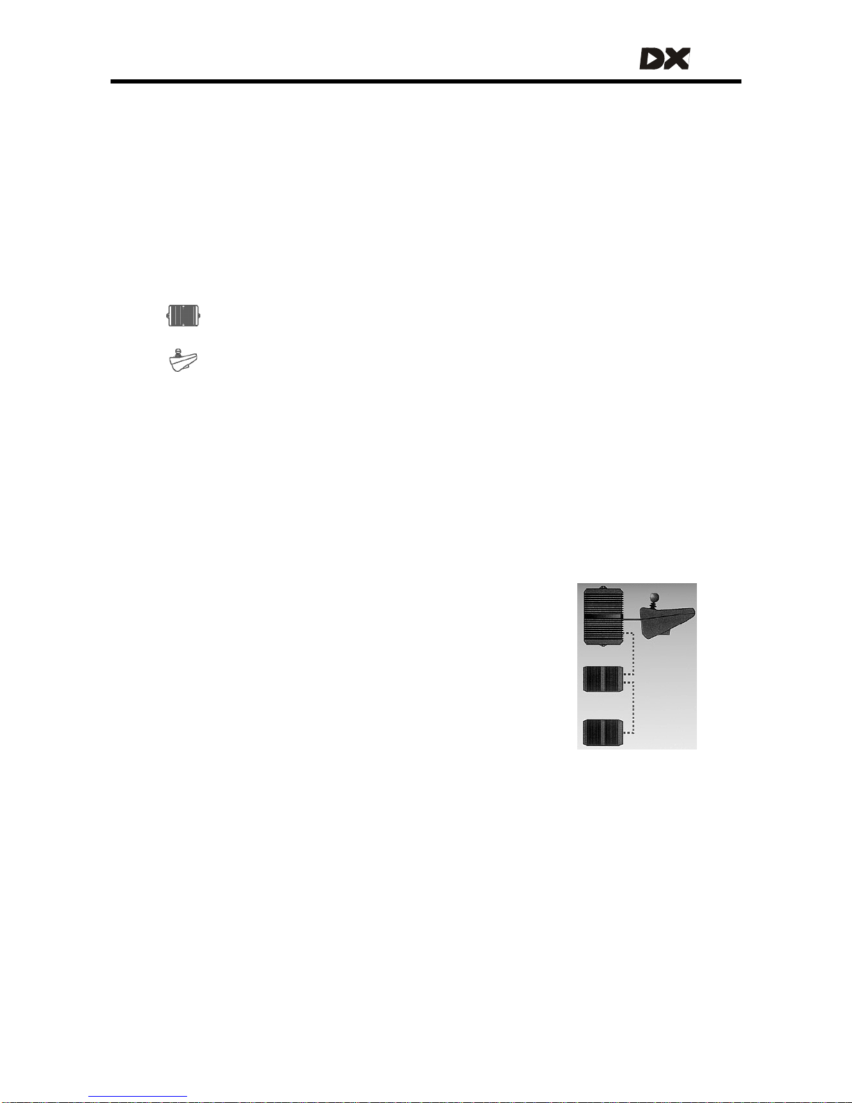
The heart of the DX System
The most basic DX control system consists of two parts:
A DX Power Module, connects to the battery and to the motors
A DX Master Remote
The Master Remote is the brain of the DX System. Every DX System must have one,
and only one. There are several different Master Remotes available to choose from:
with joystick, without joystick, ch in remote, attendant remote, etc.
DX System extensions
In addition to the Power Module and the Master Remote, many other remotes and
modules are available to extend the DX System, like:
• Secondary Remotes, for example: attendant remotes, sip ‘n puff, finger steering
• Switch input modules
• Lighting and Seating control modules
• Environmental control modules
The DX System can be extended to a maximum of 16 modules.
DX System connections
All modules are connected to each other by a DX BUS cable.
Most DX Modules have two DX BUS connector sockets. That way
you can connect another DX part easily.
DX BUS is an interface (the way the modules "talk" to each other) based on the CAN
interface, which is widely used in the automotive industry. CAN is well known for its
reliability and its fault detection. DX BUS inherits this reliability, and even improves on it.
One system fits all
Start out with a simp le system and add the modules you need at the time they
become available, or when the application requirements grow. See the Dynamic
Controls pr oduct catalogue for the latest a dditions to the product range.
9
Page 10
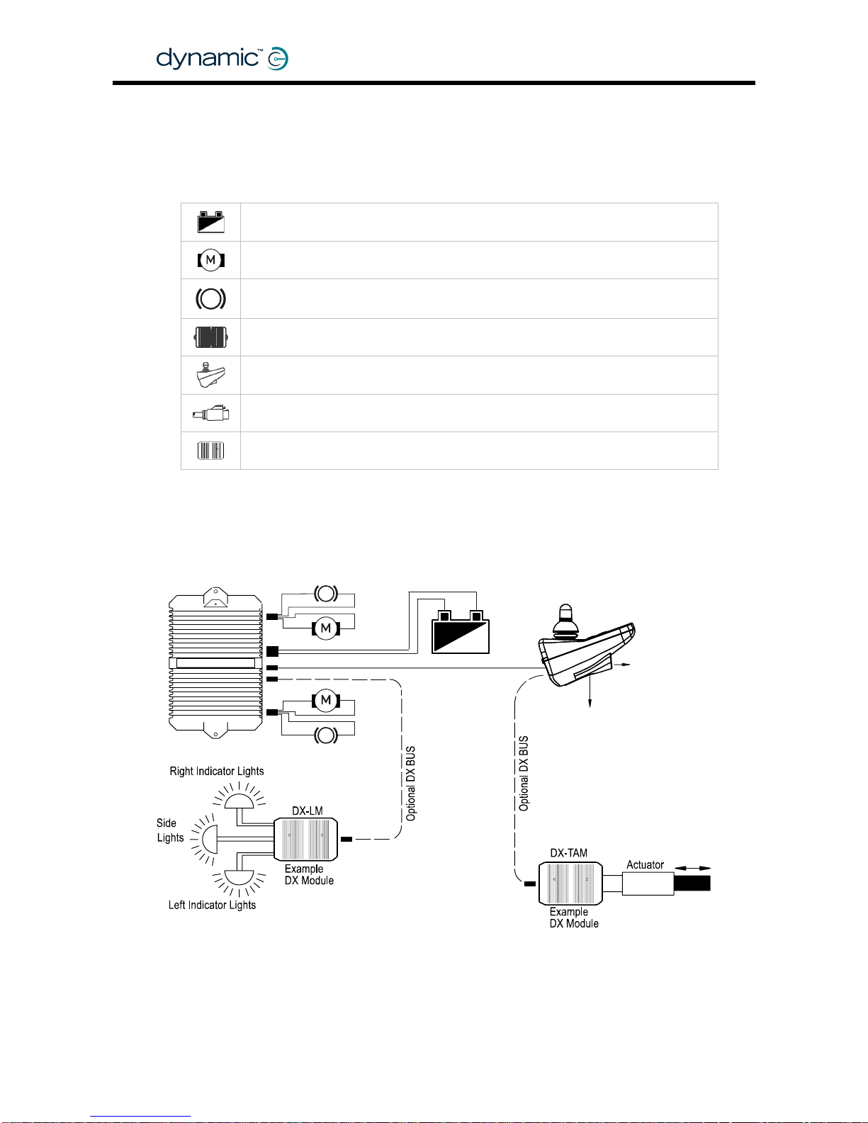
2 A typical DX powerchair setup
A standard powerchair installation with the DX System consists of the following
electrical parts:
The Batteries (section 2.2)
The Motors (section 2.3)
The Parkbrakes (section
2.4)
A DX Power Module (chapter
4)
A DX Master Remote (chapter
5)
The DX BUS cables (section
3.1)
Optional: Actuator or Lighting Modules (chapter
6)
P
PB1
M1
P
PB2
M2
P
To HHP
or Wizard
24V Batter
y
DX Master Remote
To Battery
Charger
DX Power Module
DX BUS
GBK60348
: Issue 1 – October 2007
10
Page 11
MT
2.1 Installation procedure
To install the DX System safely:
• First read and understand the DX System manual and the manuals of all the
used DX components.
• Mount all the electrical parts o f the powerchair setup (motors, parkbrakes,
batteries, DX Modules and remotes) on the powerchair. See the manuals of
the used DX Modules for the physical dimensions and mounting
recommendations.
• Do not connect any cables before all the parts of the DX System are
mounted.
• Connect the DX Power Module to the rest of the DX System with the DX BUS
cables (see section
2.1.1 for general wiring recommendations).
• Cover any unused DX BUS sockets with a GME64909 DX BUS Connector Cover.
• Conn ec t the DX Power Mo dul e to the mo tors ( see secti on
2.3.2) and the park
brakes (see section
2.4.2).
• Connect the DX Power Module to the batter ies (see section
2.2.4.1).
Do not turn on the DX System yet.
• Lift the powerchair off the ground and check the installation thoroughly
(see section
8.1)
• Program the system to the requirements of a particular powerchair or user
(see chapter
7).
• Test the system for functionality and safe ty (see chapter
8).
Warning:
Do not connect the '+' terminal of the battery to the DX System until
the powerchair is completely wired and ready for testing as
described in the
Testing section (chapter 8).
11
Page 12
2.1.1 General wiring recommendations
• Keep all cables as short as possible.
• Try to run wires in pairs or bunches.
• Do not route the motor cables near the motor case, where possible.
• Avoid wire loops, especially loops of single wires instead of wire pairs.
• Fasten cables to the powerchair frame to prevent strain on the connectors.
• Do not leave electrical connections unnecessarily exposed.
• Make sure that all vehicle sub-frames are electrically connected.
• To minimise electromagnetic emissions by the motor brushes, it may be necessary
to fit capacitors between the brush hold ers and the motor case. Make sure that
the leads are kept as short as possible. A suitable capacitor is 4n7, 250V
Polypropylene.
• For low-current signals, do not use wire sizes smaller than 0.5 mm
2
/AWG20, because
smaller wires are physically not strong enough for this application.
• For best electrical performance, the wire size must be as large as possible.
Maximum Wire
Current
Recommended
Minimum Wire Size
Power Module
60A 3 mm2 / AWG 12
80A 4 mm2 / AWG 11
100A 6 mm2 / AWG 9
The Power Module wire sizes above are appropriate for cable lengths up to
400 mm / 15". For longer cables, increase the wire si ze by 0.5 mm
2
for every
additional 200 mm / 7.5" in length. G enerally, the larger the wire size, the better the
powerchair performance will be.
• Do not use damaged or abused cables. A damaged cable can potentially
produce localised heat, sparks or arcing and as such it can cause a fire.
• Protect all cables against possible contact with flammable material.
• Where possible, the installation must prevent and/or discourage the user to
disconnect the DX BUS cable.
Warning:
1. Route the cables and fasten all DX components in a position so
that the cables, the connectors and the connector sockets do not
allow water entry or suffer from physical strain, abuse or damage,
like cutting or crushing. Take particular care on powerchairs with
movable structures like seat raise/tilt or swing-away arms. Make
sure that the cables do not extend from the powerchair so that
they can not be caught or damaged by external objects.
2. The DX BUS cable distributes 24V power to the DX modules, even
when the system is switched off. Avoid short circuit between the
DX BUS cable pins whenever a DX BUS connector is removed from
its socket. Make sure that the DX BUS connector can not reach
potential shorting points. If any protruding, bare metal screws or
pins are within reach of a DX BUS cable end, cover or plastic-coat
them to make sure that they do not cause short circuits between
DX BUS cable pins. Disconnect all the cables of the powerchair at
the powered end whenever units are replaced or moved.
3. The user maintenance schedule and the service instructions of the
powerchair must include the appropriate inspection and
maintenance requirements for the connectors and the cables.
GBK60348
: Issue 1 – October 2007
12
Page 13
MT
2.2 The batteries
The batteries provide the energy for the powerchair to drive. The batteries
are connected to the DX Power Module. The DX Power Module sends the
energy of the batteries to the motors and to the other modules.
The batteries must be operated and maintained according to the instructions of the
battery manufacturer.
2.2.1 Battery type
• 24V (commonly 2 x 12V)
• Lead -Acid / Deep Cycle Gel Cell
• Rated capacity: 20 – 120 Ah (dependent on application and Power Module)
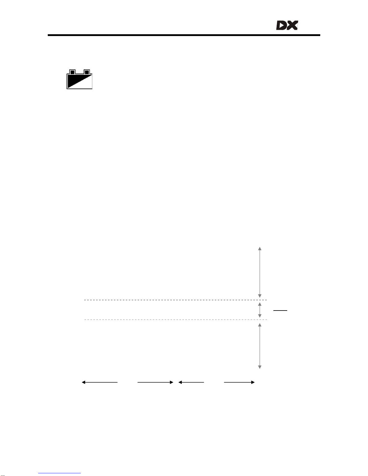
2.2.2 Battery capacity
Choose a battery capacity that is compatible with the intended use. This ensures that
the required chair range and/or operating time is achieved.
The rated capacity in Ampere-hours (Ah) of a battery is usually specified for a 20 hour
discharge rate (or 0.05 CA, a current of 5% of the rated capacity). A higher
continuous discharge current dramatically reduces the available battery capacity.
As the graph shows, when the discharge current equals the rated capacity (1 CA),
DX Saver
active (2.2.4.2)
1 2 4 6 8 10 20 40 60 2 4 6 8 10 20
Typical discharge times for lead acid batteries
Hours Minutes
Discharge time
26
22
20
18
16
24
Normal
operation
Battery
fault
Battery voltage (V)
13
Page 14
the battery does not last the expected one complete hour, but only 30 minutes,
giving an actual available capacity of only 50%.
Rated
capacity
Average
discharge current
Actual
capacity
20 Ah 40 A (2 CA) 5 Ah (25%)
20 Ah 20 A (1 CA) 10 Ah (50%)
20 Ah 12 A (0.6 CA) 12 Ah (60%)
20 Ah 8 A (0.4 CA) 15 Ah (75%)
20 Ah 1 A (0.05 CA) 20 Ah (100%)
Notes:
1. Dynamic Controls recommends to use batteries with a
capacity that is
at least twice as high as the average
discharge current.
2. New batteries often start with only 80% of their rated capacity.
After a few charging cycles the capacity will increase to 100%.
3. Deep discharging or overcharging dramatically decreases the
capacity of the battery. This damage is permanent, the battery
will never return to its original capacity.
See also section
9.5: Battery warning conditions.
GBK60348
: Issue 1 – October 2007
14
Page 15
MT
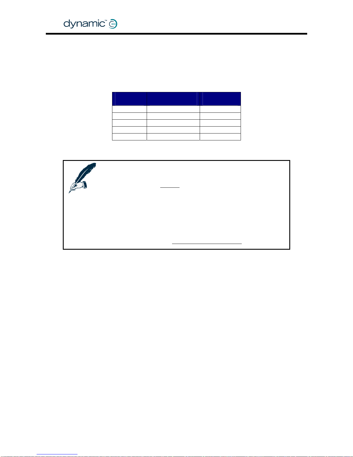
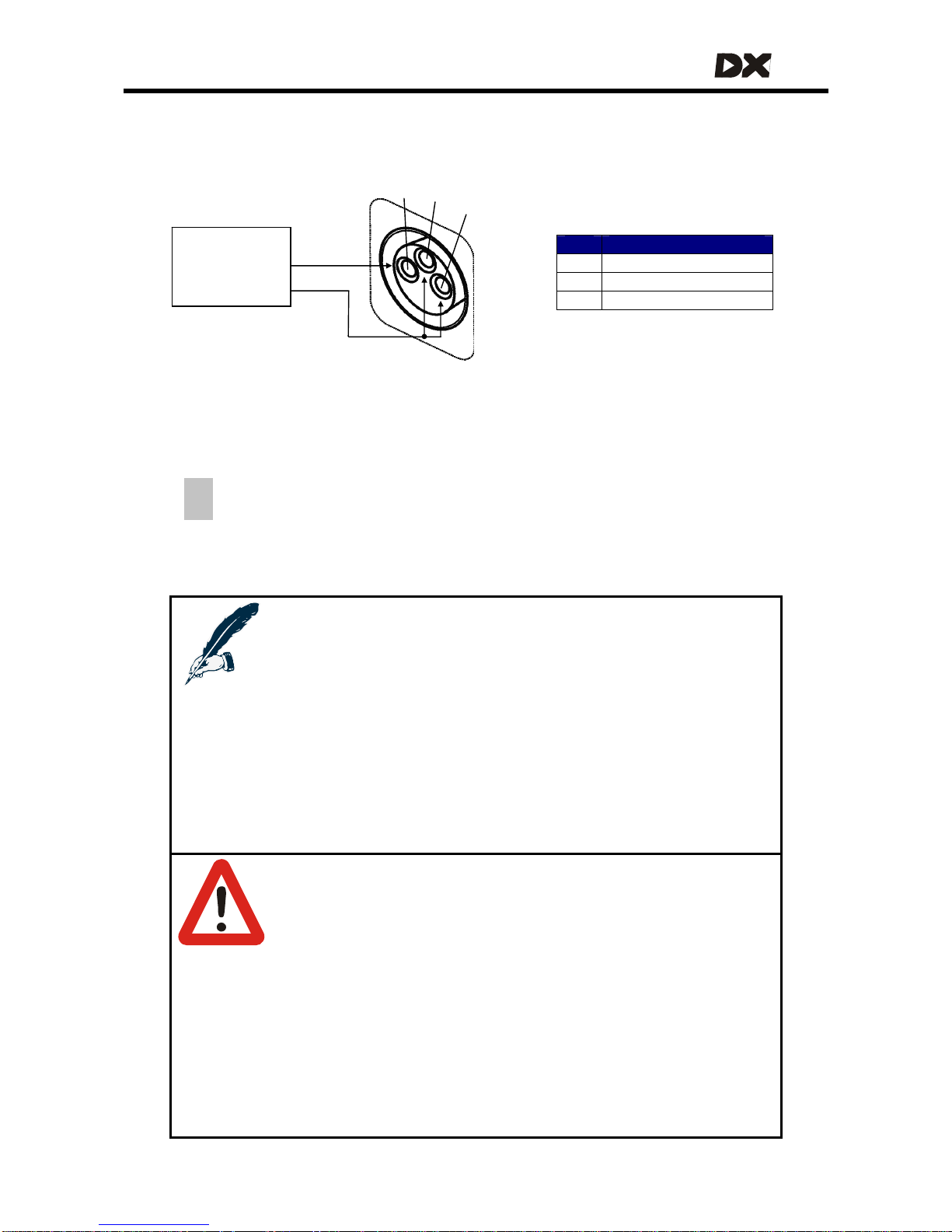
2.2.3 Battery charging
The battery charging socket of the DX System is a 3-pin XLR type normally located on
the DX Master Remote.
1
3
2
Battery
charger
Pin Signal
1 Battery Positive (B+)
2 Battery Negative (B-)
3 Drive Inhibit
B+
B-
The Drive Inhibit signal makes sure that the powerchair does not drive when the
batteries are being charged. This signal must be provided within the battery charger
plug as a connection between pin 2 and pin 3. Ensure that the battery charger is
compatible with this configuration before connecting it to the charging socket.
When turned on during charge, DX Master Remotes that have a 7-segmen t
display will show a dash to indicate that the powerchair is inhibited to drive. It
is still possible to use accessory functions like actuators.
Once the Battery Charger displays a ‘full’ battery charge, the battery charger plug
may be removed.
Notes:
1. For the exact location of the battery charging socket, see the
manual of the Master Remote that is used.
2. It is recommended to leave the system off while charging when
possible. A load during charging – especially a large load like
the use of actuators - can cause some battery chargers to think
that the battery is more empty than that it actually is.
Dependent on the specifications of the battery charger, this
can result in overcharging and possible battery damage. Read
the manual of the used battery charger for more information.
3. Overcharging dramatically decreases the lifespan of a battery.
Warnings:
1. Do not disconnect the batteries or open the circuit breaker
during charging. See the manual of the battery charger for
more information.
2. If during charging the battery gauge starts to flash to indicate
an overvoltage condition, immediately turn off either the
battery charger or the DX System.
3. To remove the charger plug, pull in the direction of the cable.
Do not try to turn the plug.
4. The battery charger used must be correctly selected and
adjusted according to the instructions of the battery
manufacturer. Failure to do so can damage or destroy the
batteries, give poor range, or be potentially dangerous.
15
Page 16
2.2.4 Battery protection
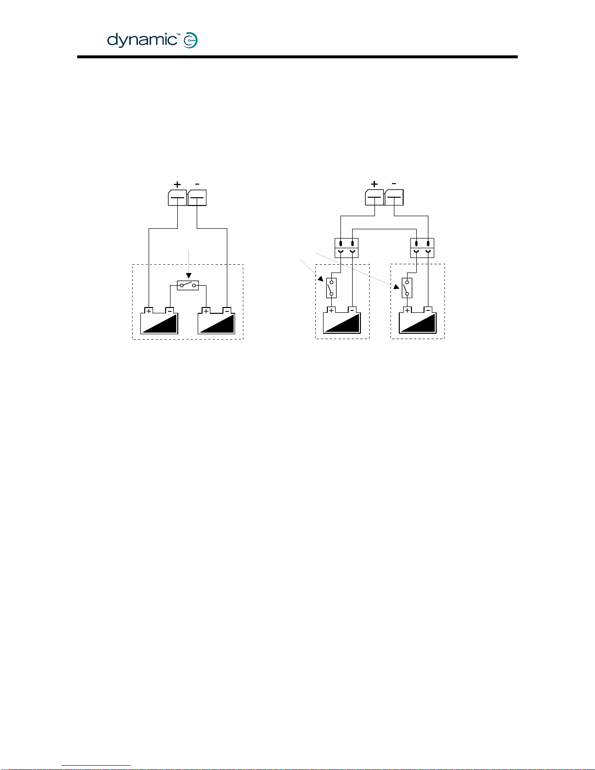
2.2.4.1 Thermal circuit breakers
To protect the batteries and the system cables f rom external short circuits, a therma l
circuit breaker or fuse must be installed between the batteries and the rest of the
system - as close as possible to the batteries. If the two batteries are permanently
wired together in a single battery box, the best position for the circuit breaker is
between the two batteries. If the batteries are separated in individual battery boxes,
each battery requires its own circuit breaker.
The circuit breaker or fuse must be of the slow acting type. The rating of the circuit
breaker must be appropriate for the power requirement, inclu ding the total weight of
the chair, the battery capacity and the wiring.
GBK60348
: Issue 1 – October 2007
16
2.2.4.2 Battery Saver
If the battery Voltage falls below 21V, the DX System reduces the performance of the
powerchair. This
• pro tects th e battery
• gives the powerchair a longer range before the battery is completely empty
• gives the user a physical warning that the battery is almost empty before
the battery is damaged.
2.2.4.3 High Voltage Rollback
High Voltage Rollback is a battery protection feature that is especially useful for users
who have to drive downhill often.
When a powerchair drives downhill, the Power Module sends the generated motor
current to the battery. However, if the battery is fully charged already, it can not
accept the generated current anymore. This causes the battery voltage to become
too high, which can cause damage to the battery or the controller.
High Voltage Rollback gradually decreases the speed of the powerchair until the
battery can accept more current. The deceleration of the powerchair gives a timely
physical wa rning to the us er to take corrective acti o n , like turni ng on the lights or
slowing down.
High Voltage Rollback can be enabled wi th the Wizard (see
4.3.4.6).
Single Battery Box
Thermal Circuit
Breake
r
Separate Battery Boxes
Thermal Circuit
Breake
r
s
Page 17
MT
2.3 The motors
The wheel motors control the powerchair speed and direction. The motors are
connected to the DX Power Module.
Note:
If one of the motors is not connected to the DX Power Module, the
DX System detects a Motor Fault (see
9.6) and prevents driving.
2.3.1 Motor types
Drive motor
type
Motor
resistance
Current Power
Module
Min. wire size
2 x 60A DX-PMB 3 mm
2
2 x 75A DX2-PMA75L 4 mm
2
2 x 80A DX-PMB2 4 mm
2
24V DC* 0 – 0.5 Ω
1 x 120A
(2x 60A
parallel)
DX-PMB-S 3 mm
2
(two wires in parallel,
each carrying 60A)
24V AC
Gearless
Brushless
N/A 2 x 100A DX-GB 6 mm
2
*12V DC motors can be used if the controller is programmed to half speed.
Notes:
1. The motor wire sizes above are appropriate for motor loom
lengths up to 400 mm. For longer looms, increase the wire size
by 0.5 mm
2
for every additional 200 mm length. Generally, the
larger the wire size, the better the powerchair performance.
2. The chosen size and length of the motor wires can affect the
optimum setting of the Load Compensation parameter (see
section
4.3.2.3).
3. Gearless Brushless motors and the DX-GB Power Module are
not covered in this manual. Any reference to motors or motor
connectors in this manual is referring to DC motors and the
applicable Power Modules. Read the DX-GB manual for more
information about the Gearless Brushless system.
Warning:
The Power Module must be correctly configured for the
applicable motor resistance with the Load Compensation
parameter, see section
4.3.2.3. Failure to set this parameter
correctly can be dangerous for the powerchair user, because
the chair can become uncontrollable.
17
Page 18
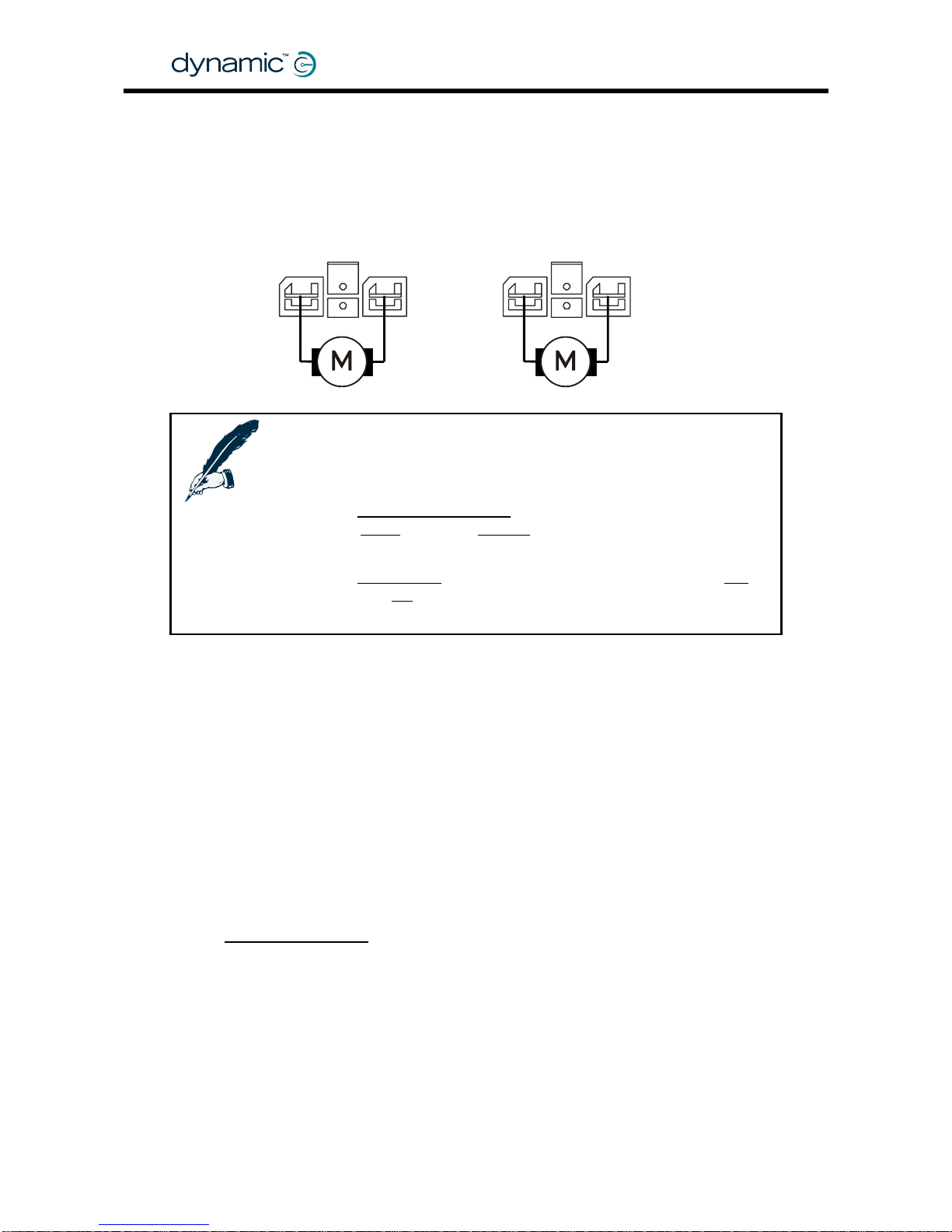
2.3.2 Motor connections
The DC motor cables must be connected to the Motor/Parkbrake connectors of the
DX Power Module.
M2 / Right M1 / Left
+
-
+
-
Notes:
1. Keep the motor cables as short as practical to minimise
voltage drops in the cable.
2. If the
Left/Right Motor Swap parameter (see section 4.3.2.7) is
set to
Swap instead of Normal, the Power Module will assign
M1 to the Right motor and M2 to the Left motor.
3. If the
Motor Invert parameter (see section 4.3.2.8) is set to Yes
instead of
No, the polarity of the + and - terminals will be
swapped.
2.3.3 Motor resistance
The resistance of different motor types varies typically between 20 and 350 mΩ.
The DX Power Module must know what the motor resistance is because the motor
resistance determines the internal voltage drop in the motor when the motor is under
high load (when the motor needs a lot of current to do a task).
If the voltage inside the motor drops too much, the performance of the powerchair
will be decreased:
• It will feel unresponsive
• It will slow down or stop when it tries to go up a slope or up a sidewalk edge.
The DX
Load Compensation feature compensates for the voltage drop in the motor.
If the motor has a high resistance, the Power Module applies a higher voltage to the
motor terminals in high load conditions. This prevents a loss of performance.
To find o ut how to determine the motor resistance and how to progr am Load
Compensation, see section
4.3.2.3.
GBK60348
: Issue 1 – October 2007
18
Page 19
MT
2.4 The parkbrakes
The parkbrakes make sure that the powerchair does not move when it is
not actively driven or when the power is turned off.
For safety, parkbrakes are always applied unless they are actively
released, either by the Power Module or manually with a parkbrake
release switch.
P
Note:
If the parkbrakes are not connected to the DX Power Module, the DX
System detects a Parkbrake Fault (see
9.6) and prevents driving.
2.4.1 Parkbrake types
• Fail-saf e ele c tro-magne tic parkbrak es attached to each motor
• 24V or 12V
• 1A – 2A maximum current per parkbrake (dependent on the Power Module used,
see the PM manual for the correct specification)
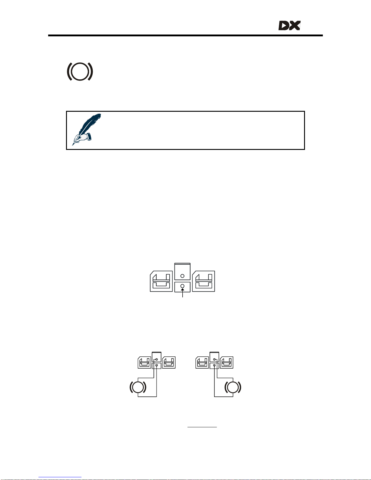
2.4.2 Parkbrake configurations
The parkbrake connection pins are located in the mo tor connectors of the DX Power
Modules.
PB+
PB-
2.4.2.1 Two 24V parkbrakes – Dual, M1 and M2
In the dual configuration each parkbrake is driven from a separate output.
For this configuration the DX Power Module
Park Brake parameter (see section
4.3.3.1) must be set to Dual.
P
P
24V
Park
Brake
24V
Park
Brake
M2
M1
19
Page 20
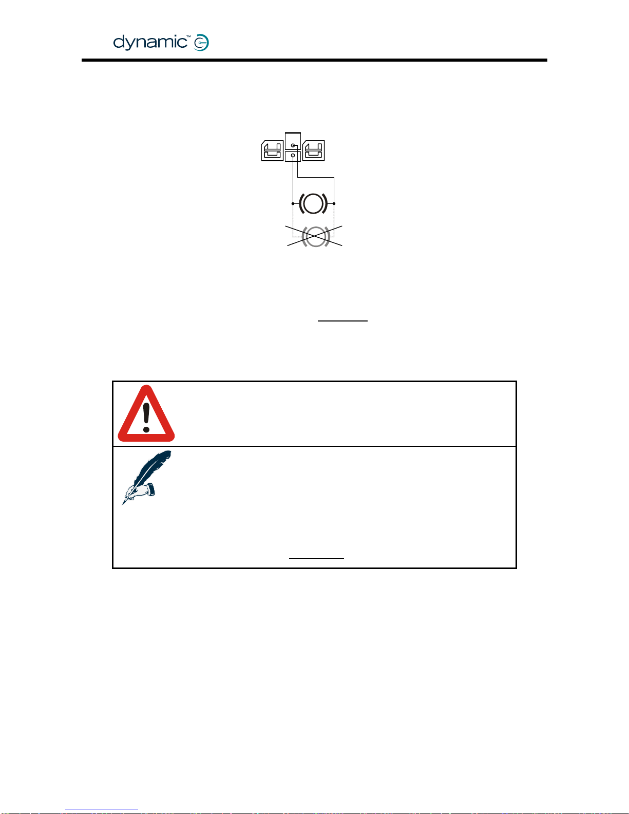
2.4.2.2 One 24V parkbrake – Single, M1 only
In the single configuration the parkbrake is driven from the M1 output only.
For this configuration the DX Power Module
Park Brake parameter (see section
4.3.3.1) must be set to Single.
Do not connect
a 2
nd
24V park-
brake like this
24V
Park
Brake
M1
P
P
Warning:
Do not connect a second 24V parkbrake in parallel to M1, because
an open circuit fault in only one of the two parkbrakes can not be
detected. Always use the dual configuration for two 24V parkbrakes.
Note:
1. If in this configuration the parkbrake is connected to M2
instead of M1, a Left Parkbrake Fault (flash code 5) will occur.
2. If the Park Brake parameter is set to Dual in this configuration
(with no parkbrake connected to M2), a Right Parkbrake Fault
(flash code 6) will occur.
See also section
9.6: Flash codes
GBK60348
: Issue 1 – October 2007
20
Page 21
MT
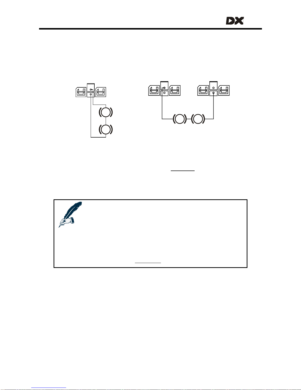
2.4.2.3 Two 12V parkbrakes
If the powerchair has two 12V parkbrakes, both can be driven from a single 24V
output by connecting the 12V parkbrakes in series. Alternatively, the 12V parkbrakes
can be connected to both parkbrake outputs. In the latter case the parkbrakes will
be driven from the PB+ output of M1.
For both these configurations the DX Power Module
Park Brake parameter (see
section
4.3.3.1) must be set to Single.
12V
Park
Brake
M1
12V
Park
Brake
M1
12V
Park
Brake
12V
Park
Brake
PB+ PB-
P
P
P P
M2
12V parkbrakes configuration 2 12V parkbrakes configuration 1
Notes:
Configuration 1: if the park brakes are connected to M2 instead of
M1, a Left Parkbrake Fault (flash code 5) will occur.
Configuration 2: if PB+ is connected to M2 instead of M1, a Left
Parkbrake Fault (flash code 5) will occur.
Both configurations: if the Park Brake parameter is set to Dual, a Right
Parkbrake Fault (flash code 6) will occur.
See also section
9.6: Flash codes
21
Page 22
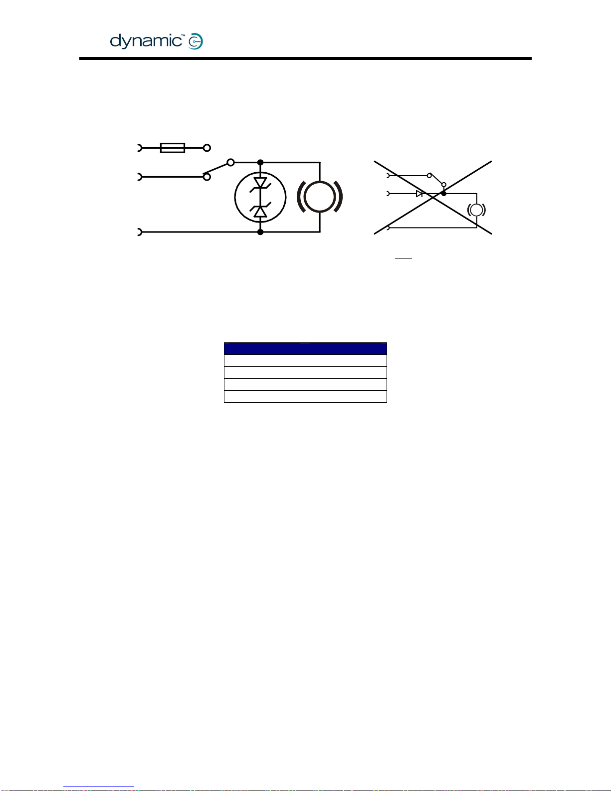
2.4.3 Manual parkbrake release switch
Manually operated parkbrake release switch es must be fitted together with a suitable
suppression device across each parkbrake.
The suppression device prevents the genera tion of high voltage transients causing
possible damage to the Power Module or to the parkbrake release switch itself.
Some suitable suppression devices are:
Always fit a suppression device
2x zener diode
39V, min 2W
Surge: min 50W, 2ms
Parkbrake
PB+
Battery+
Fuse
Release
switch
PB-
Do NOT
connect like this
P
P
Motorola Philips
3EZ39D5 BZX70C36
3EZ36D5 BZX70C39
1N5365A BZT03C36
1N5366A BZT03C39
2.4.4 Mechanical parkbrake release
To make it possible to manually push the chair if the battery is empty, some form of
mechanical clutch or parkbrake release is required. For safety, if the parkbrake is
mechanically released the chair must not be able to drive.
One way to achieve this is to put a switch that disconnects the parkbrake from the
Power Module in the mechanical parkbrake release. When the parkbrake is
disconnected from the Power Module a Parkbrake Fault will occur and the
powerchair will not be able to drive.
2.4.5 Parkbrake operation and programming
For safety, parkbrakes are always mechanically applied in their electrical "off"-state.
This makes sure that the parkbrakes do not consume energy when the powerchair is
turned off. It also makes sure that the powerchair does not roll away if the battery
becomes empty on a slope.
To release the parkbrake, it must be "energised" (switched on), either by the Power
Module or manually with a parkbrake release switch.
• Energise a parkbrake to release it
• De-energise a parkbrake to apply the brake.
GBK60348
: Issue 1 – October 2007
22
Page 23
MT
2.4.5.1 Electrical delay
When the powerchair stops, the parkbrakes will be applied. However, the parkbrakes
must not be applied too early. The parkbrakes must
not engage
• if the powerchair stops to change direction (for example forward to reverse)
• before the powerchair has come to a halt after high deceleration
• before the powerchair has come to a halt when parking on a slope
The
Neutral to PB Delay parameter (see section 5.3.10.2) is the delay between zero
speed demand and the moment that the parkbrakes are de-energised.
The correct value of this parameter is dependent o n the mechani c s o f the parkbrake
that is used on the chair. The delay must be longer for fast acting parkbrakes.
This parameter is set by the powerchair manufacturer for specific powerchair types. It
cannot be adjusted by dealers.
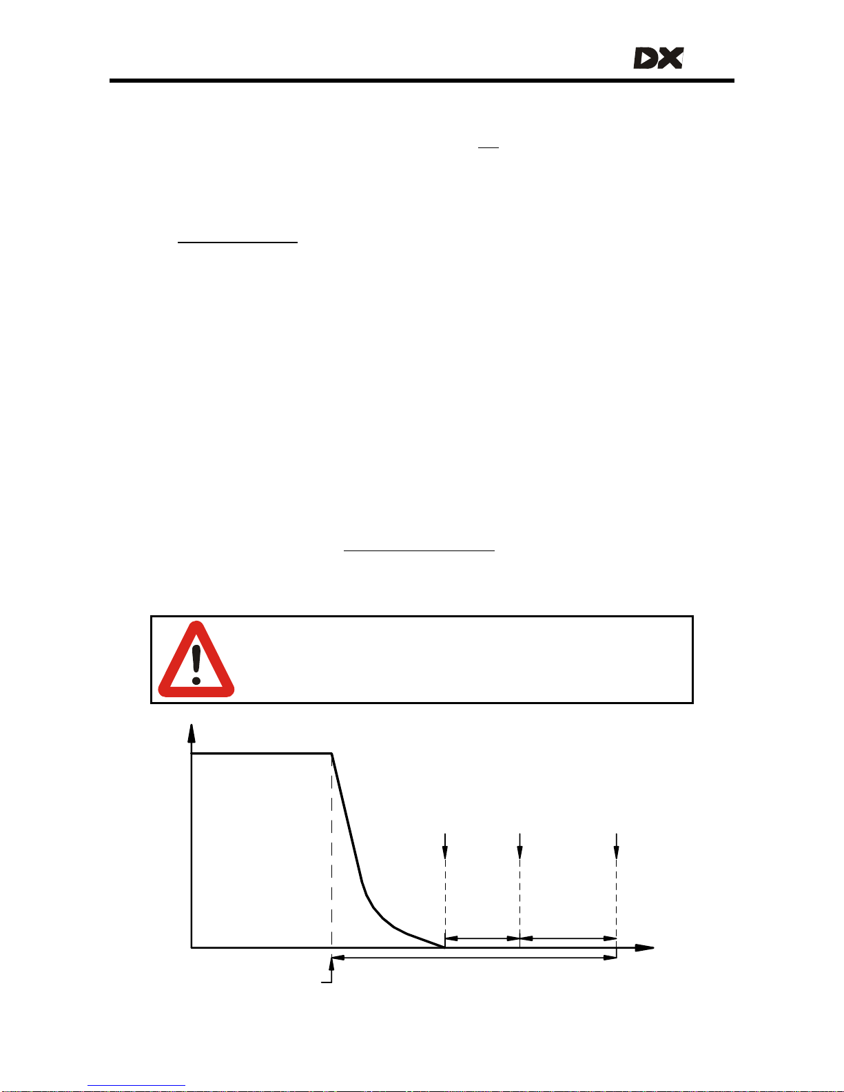
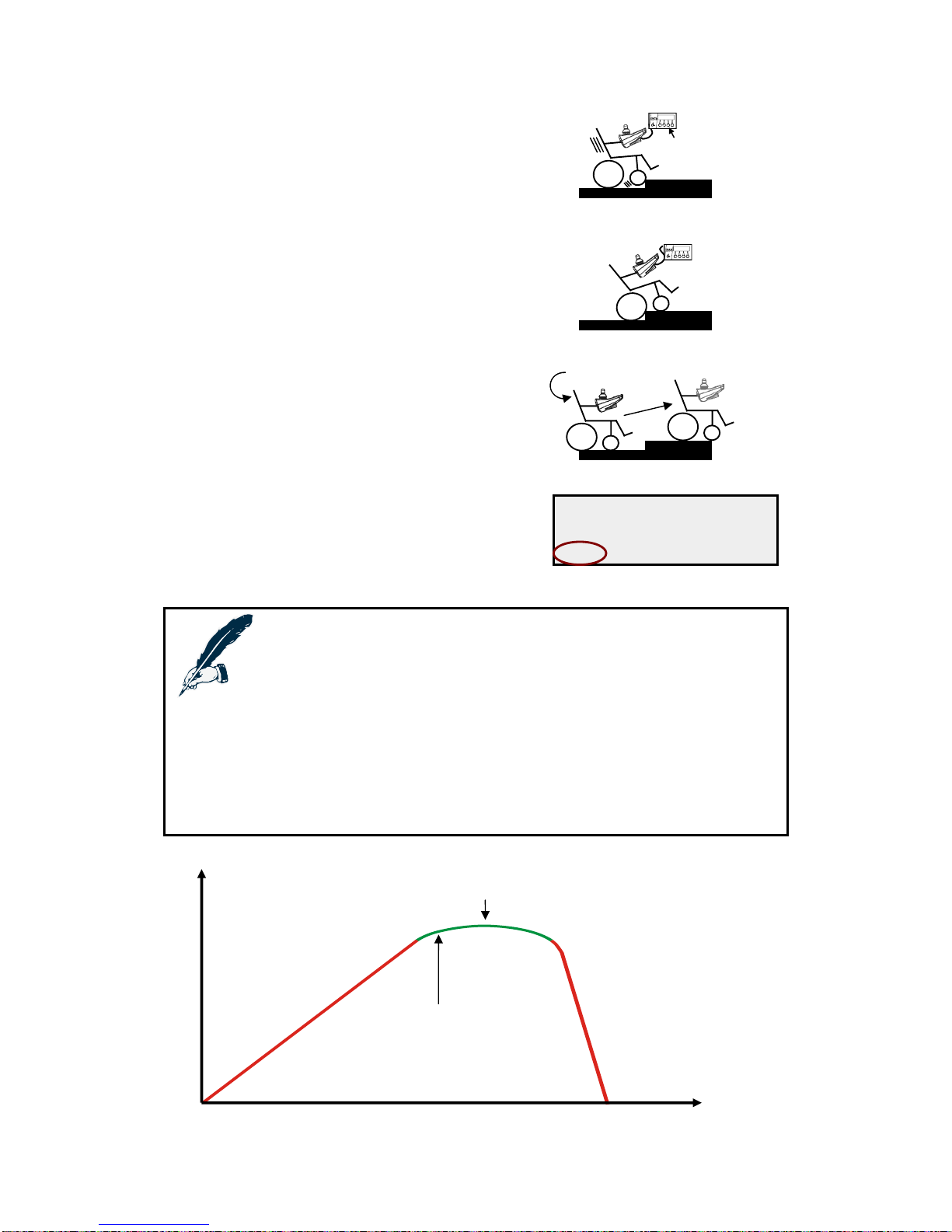
2.4.5.2 Mechanical delay
There is a significant delay between the moment that the parkbrake is de-energised
and the moment that the parkbrake actually engages mechanically. This delay
becomes important when the powerchair decelerates and stops. When the
powerchair has stopped, it will take some time before the parkbrakes are actually
engaged.
The Power Module uses the motors to brake and hold the powerchair during the time
that the parkbrakes are not engaged (active motor braking). The motor braking time
can be programmed with the
Brake / Bridge Off Delay parameter (section 4.3.3.2).
After the time defined in the Brake / Brid ge Off Delay parameter the Power Module
will switch off the motors.
Warning:
Make sure that the Brake / Bridge Off Delay time is greater than the
mechanical delay of the parkbrakes used. The parkbrakes must
engage before the motors turn off, or the chair will roll away.
Brake / Bridge
Off Delay
Speed
Demand
Active Motor Braking
Parkbrakes engaged
Motors switched off
Neutral to
Parkbrake
Delay
Parkbrake
de-energised
Zero
Speed
demand
decreases
according to
deceleration
parameter
Joystick returned
to the center
23
Page 24

GBK60348
: Issue 1 – October 2007
24
Page 25
MT
3 The DX BUS
DX BUS is the interface (the way the modules "talk" to each other) that connects all
the DX components together.
The DX BUS interface is based on CAN-Bus tech nology, which is commonly used in
safety critical applications like automotive and industrial control networks. CAN
provides extremely robust data reliability wi th excellent error detection and correction
capabilities. This makes the DX BUS a safe and fault tolerant data network.
The DX BUS also distributes power to the DX Modules and can safely carry up to 12
Ampere continuously.
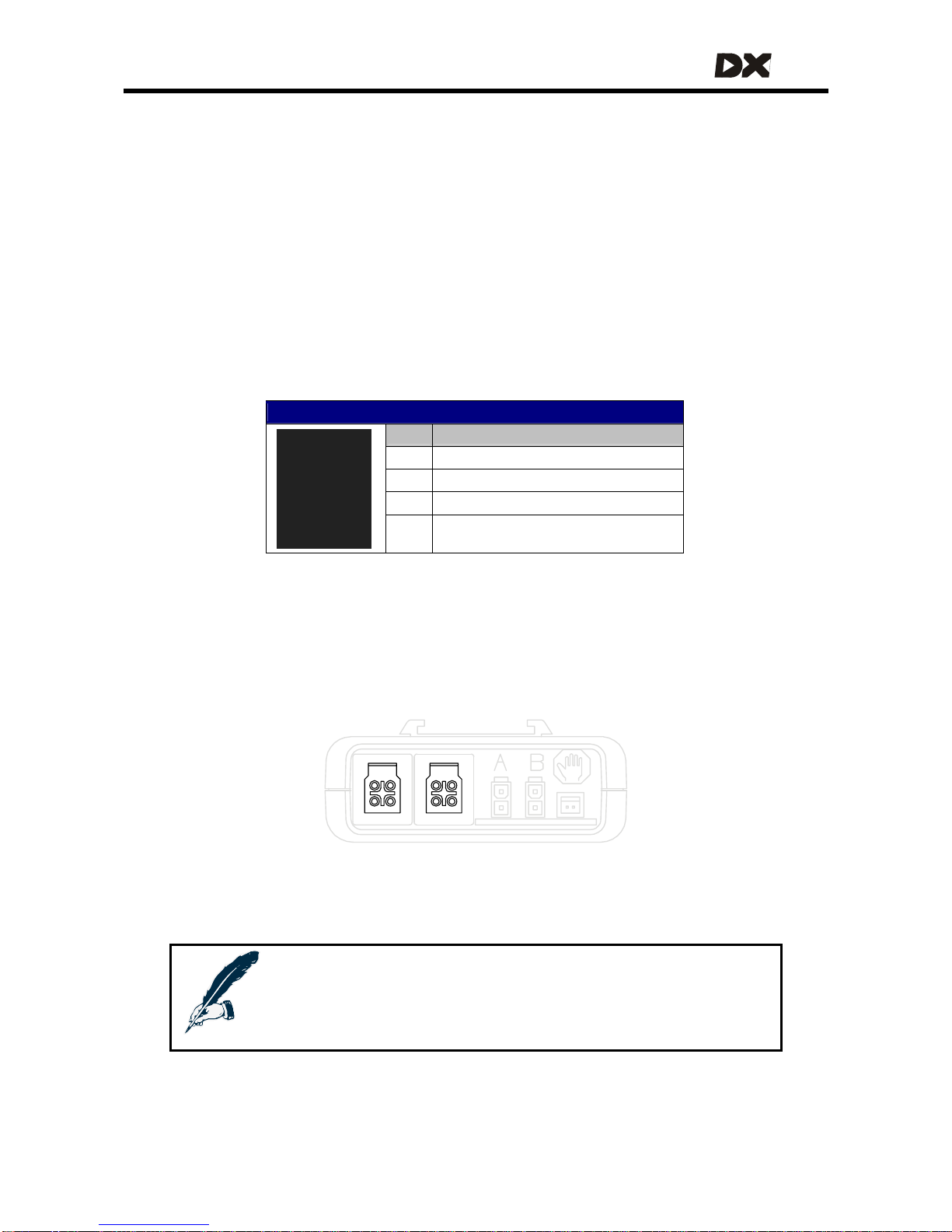
DX BUS Connector Pinout
Pin Function
1 Communications – CANL
2 Communications – CANH
3 DXB+ (24 V, fused)
4 DXB- (0 V)
CAN-H and CAN-L are used for communication between the modules.
DXB+ and DXB- supply power to the modules and to the loads connected to them.
The maximum continuous current over the DX BUS DXB+ and DXB- wires is 12A.
Most DX devices have two DX BUS connectors
Notes:
Dynamic recommends to fit unused DX BUS connectors with a
GME64909 DX BUS Connector Cover. This also complies with
ISO 7176 requirements.
25
Page 26
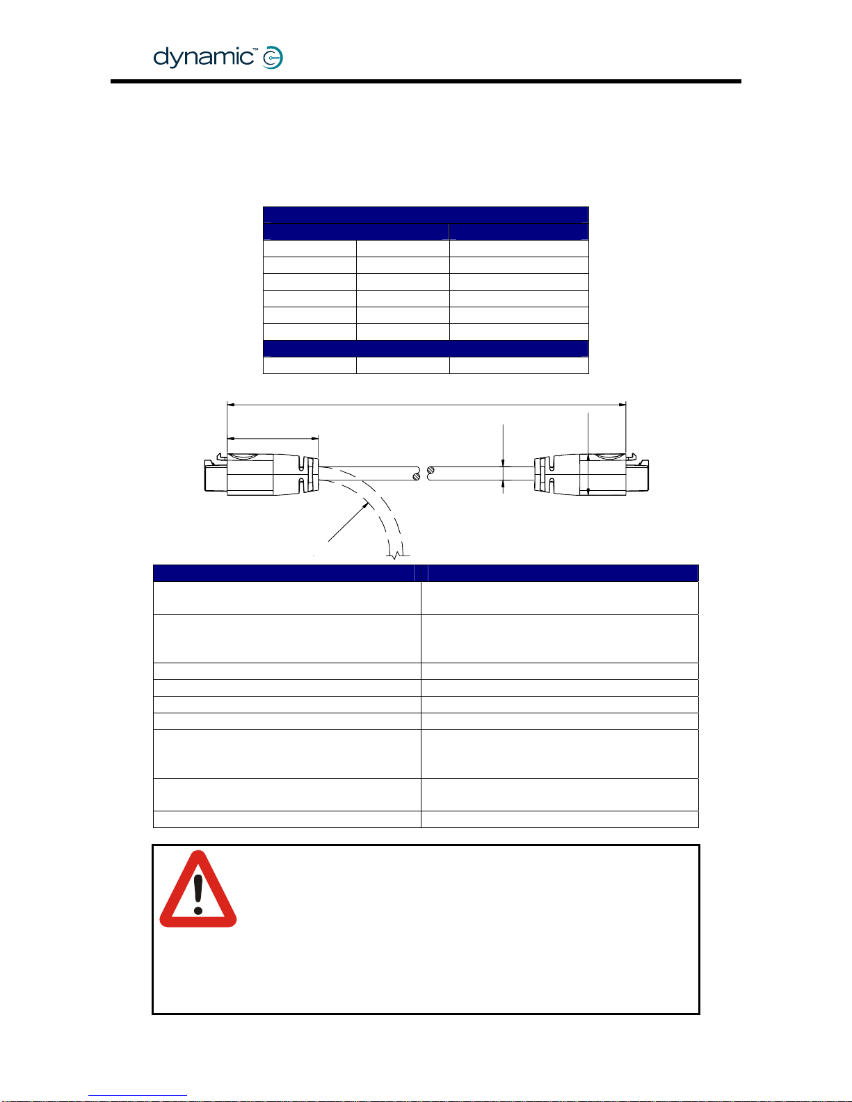
3.1 The DX BUS cable
Cable specifications - straight cable
The part number of the straight cable is GSM630YY, where YY = the length in 100 mm.
DX BUS cable straight
Length Part/Order number
300 mm 1 ft GSM63003
500 mm 1' 8" GSM63005
1.0 m 3' 3" GSM63010
1.5 m 4' 11" GSM63015
2.0 m 6' 7" GSM63020
2.5 m 8' 2" GSM63025
DX BUS cable with Ferrite bead to improve EMC
2.0 m 6' 7" GSM63020F
GBK60348
: Issue 1 – October 2007
26
Parameter Value
Contact Resistance (per contact)
As per IEC 512-2, Positronic
3 mΩ nom, 7 mΩ max
Wire resistance @ 20°C
DXB+
DXB-
15.1 mΩ/m, 4.6 mΩ/ft
8.5 mΩ/m, 2.6 mΩ/ft
Operating Current (DXB+/DXB-) 12 A nom, 20 A RMS max
Connector Latch Holding Force 40 N min
Cable Strain 100 N max (accidental, non-repetitive)
Cable Flex Force 10 N max
Minimum Cable Bend Radius
Flexing values for (T > –10°C/14°F)
10 mm / 0.39 inch - fixed installation
25 mm / 1 inch - occasional flexing
50 mm / 2 inch - frequent flexing
Operating Temperature
(ambient, fixed installation)
–25°C to +50°C
–13°F to +12 2°F
Cable Temperature Rating 80°C / 176°F (internal operating temp)
Warning:
The specified bend/flex radiuses are minimum values and must be
considered as a guideline only. Where frequent flexing is part of the
intended application, the installer must ensure an appropriate
bend/flex radius for the intended and foreseeable environmental
conditions. Extreme cold temperatures considerably reduce cable
flexibility. Appropriate life testing must be carried out to
determine/confirm the expected service life and inspection and
maintenance schedule.
35
YY x 100 ± 10
Ø7.0
13 x 16
R
-
B
E
N
D
Page 27
MT
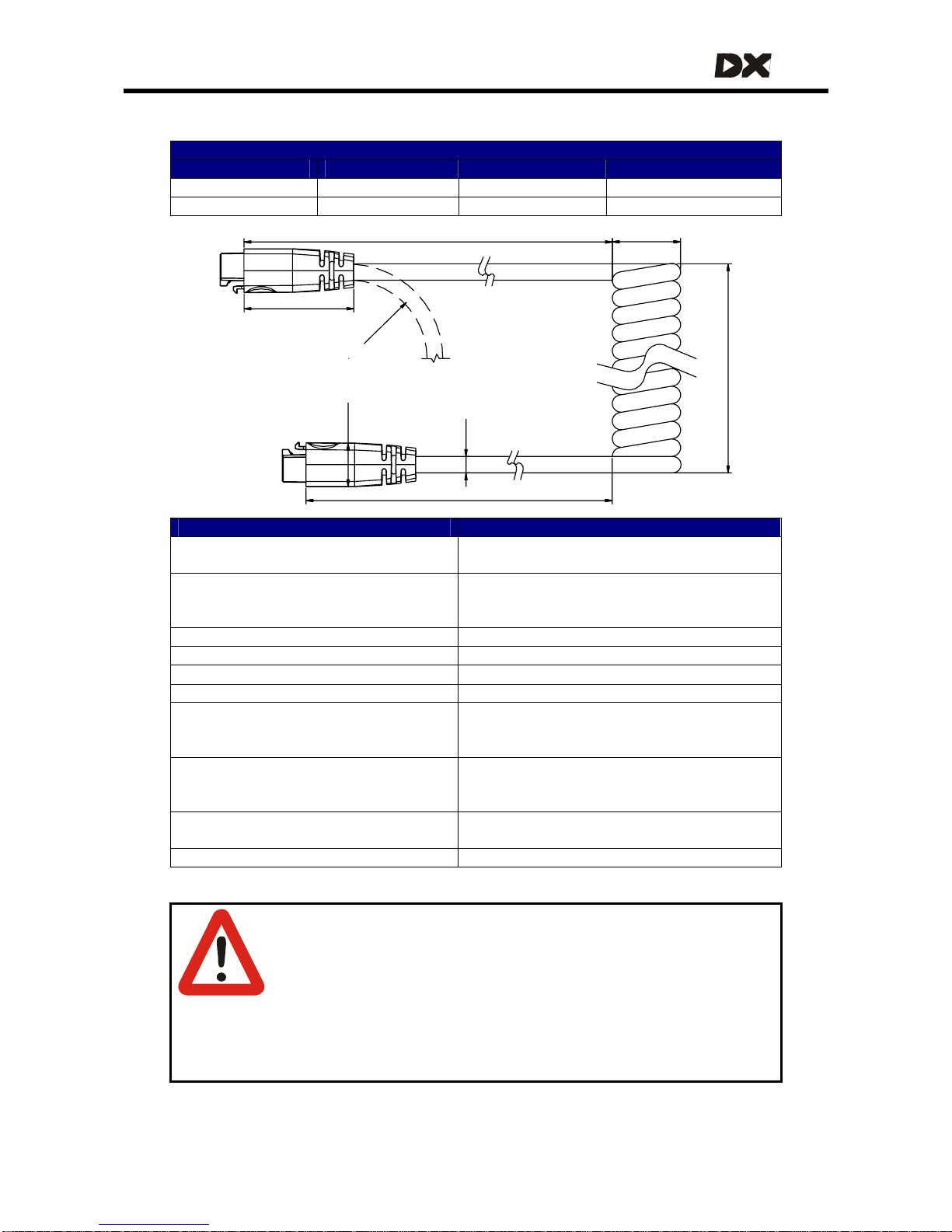
Cable specifications – curly cable
DX BUS Curly Cable
Tail Length La Coil Length Tail Length Lb Part/Order number
200 mm / 8 inch 300 mm / 1 ft 200 mm / 8 inch GSM63051
500 mm / 1'8" 300 mm / 1 ft 200 mm / 8 inch GSM63052
R
-
B
E
N
D
La ± 20
Ø26 ± 2
300 ± 30 approx. 40 coils
compressed coil length
Lb ± 20
Ø7.5
13 x 16
40
Parameter Value
Contact Resistance (per contact)
As per IEC 512-2, Positronic
3 mΩ nom, 7 mΩ max
Wire resistance @ 20°C
DXB+
DXB-
15.1 mΩ/m, 4.6 mΩ/ft
8.5 mΩ/m, 2.6 mΩ/ft
Curly Cable electrical length 2.3 m / 7'6" nom for the coiled section
Operating Current (DXB+/DXB-) 12 A nom, 20 A RMS max
Connector Latch Holding Force 40 N min
Cable Strain 100 N max (accidental, non-repetitive)
Spring Force - extension refers to the
coiled section
< 20N @ 2x extension (T > 10°C/50°F)
< 50N @ 2x extension (T > –10°C/14°F)
< 30N @ 3x extension (T > 10°C/50°F)
Minimum Cable Bend Radius
Flexing values for (T > –10°C/14°F)
20 mm / 0.8 inch - fixed installation
30 mm / 1.2 inch - occasional flexing
50 mm / 2 inch - frequent flexing
Operating Temperature
(ambient, fixed installation)
–25°C to +50°C
–13°F to +12 2°F
Cable Temperature Rating 80°C / 176°F (internal operating temp)
Warnings:
1. Do not extend the spring coils below 0°C. Do not extend the coils
farther than 2x compressed length below 10°C, or 3x compressed
length above 10°C. Avoid extension above 3x compressed length
because this can cause a permanent stretching of the coil.
2. Make sure that no spring force is applied to the DX BUS connector;
fasten a strain relief or cable tie on or near to the coiled section of
the cable.
27
Page 28
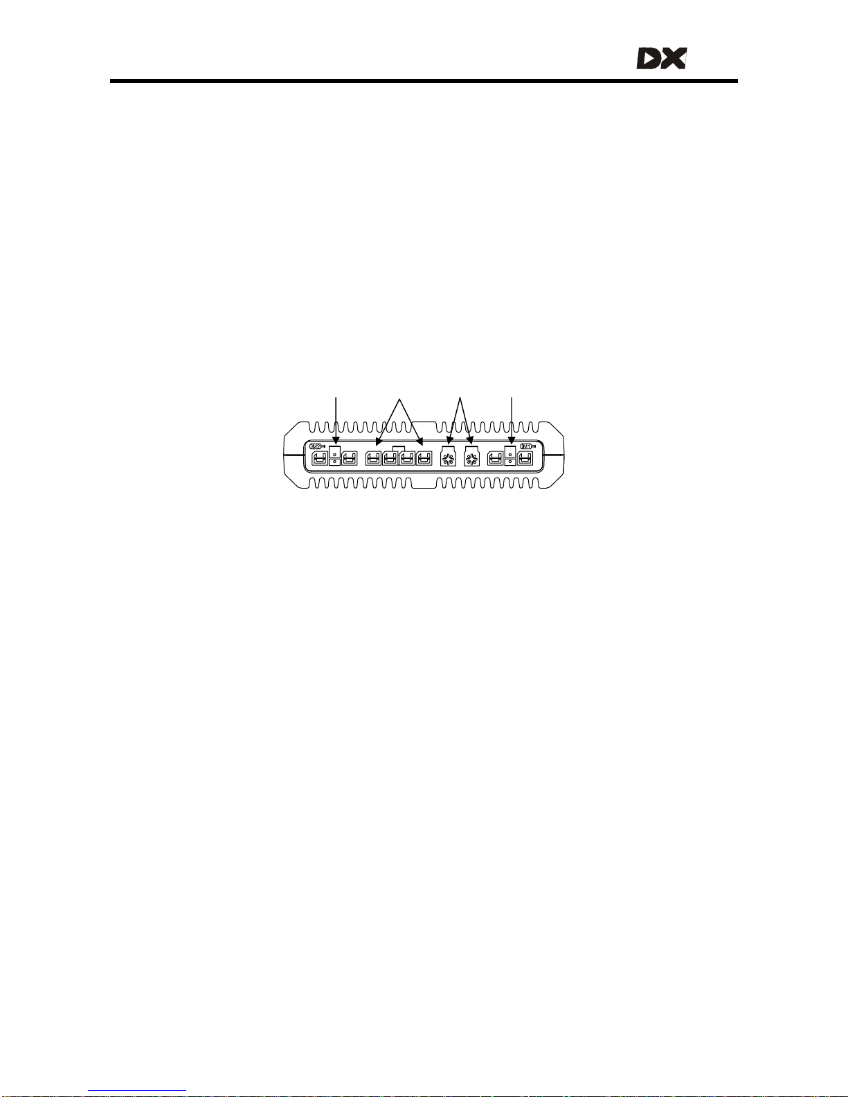
3.2 DX BUS Module connection layout
DX Modules normally have one or two DX BUS sockets for system interconnections.
Smaller DX Modules can have a permanently mounted cable ending in a DX BUS
plug, instead of DX sockets.
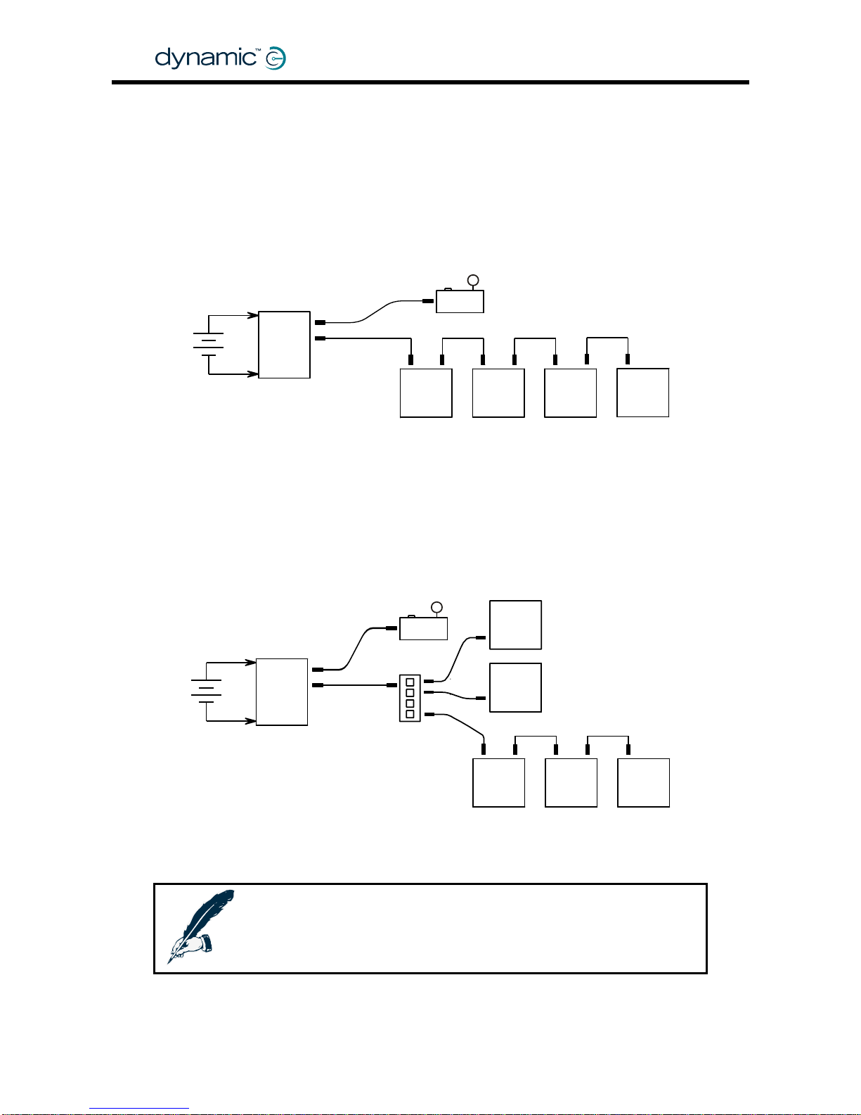
The optimu m connectio n lay out is depend ent on the type of module s th at are
present in the DX System. Low-current modules can be co nnected in series. This
provides a low-cost and simple solution.
ause a voltage drop on the DX BUS when they are connec ted far away from the
Because of the internal resistance of the DX BUS cable, high-current modules can
c
Power Module. For this reason all high-current DX Modules (for example actuators
and lights) must be connected as close to the Po wer Module as possible, preferably
in parallel.
DX modules connected in series
DX Master Remote
DX
Power
Module
DX
module
DX
module
DX
module
DX
module
24V
DX BUS
DX BUS
High-current DX modules connected in parallel
24V
DX
power
module
DX BUS
DX BUS
DX
module
HIGH I
DX
module
HIGH I
DX
module
HIGH I
DX
module
LOW I
DX
module
LOW I
DX Remote
DX splitter box
DX-SKT-X4
Note:
l length of all DX BUS cables together must not exceed 15 m.
The tota
GBK60348
: Issue 1 – October 2007
28
Page 29
MT
4 The DX Power Module
The DX Power Module converts the speed and direction signals generated by a DX
Remote into high current outputs. These outputs drive the motors and activate the
parkbrakes.
The Power Module must be connected to:
• The DX BUS (see chapter
3)
• The battery (see section
2.2)
• The mo tors (see section
2.3)
• The parkbrakes (see section
2.4).
The Power Module is fully programmable for a wide range of powerchair types and
user needs.
M/PB-2 Battery DX BUS M/PB-1
4.1 General Power Module features
• D i g ital motor con tro l
• Supply Voltage compensation
• Motor resistance and load compensation (see 4.3.2.3)
• Tracking (veer) compensation (see
4.3.2.5)
• Smart curre nt limiting and temperature limiting (see
4.3.2.1 and 4.3.4.7)
• Left/Right Motor swap option to facilitate motor cabling (see
4.3.2.7)
• Motor connector polarity swap for different motor polarity options (see
4.3.2.8)
• Single or dual parkbrakes (see
2.4.2)
• Programmable parkbrake delay (see
4.3.3.2)
• Dynamic braking in neutral
• Protected against external events such as:
o reverse battery polarity
o battery undervol tage and overvoltage (see
4.3.4.6)
o motor or parkbrake overload (see
4.3.2.9)
o external short circuits
• Extensive range of powerchair system safety and protection features such as:
o open circuit motor detection
o open and short circuit Park Brake detection
o controlled speed reduction to a stop if a fault is detected (see
4.3.2.6)
o protected against runaway in the event of an internal hardware failure
29
Page 30
• Electromagnetically compatible:
o low RF emissions
o high immunity to RF transmissions
• Built-in diagnostics with status LED and fault logging
• Watchdog, CPU, ROM and RAM testing at power up
• Compact, rugged enclosure with robust mounting points
• Environmentally compatible (sealed to IP54)
Warning:
This manual gives a description of a generic DX System and Power
Module use. It must be read together with the installation manual of
the actual Power Module that is installed on the powerchair.
Correct installation and programming are essential to ensure
optimum performance and safety.
4.2 Available Power Modules
DX
Power Module Current Motor type Lighting
DX-PMB 60A dual 24V DC no
DX-PMB2 80A dual 24V DC no
DX-PMB-S* 120A single (2x 60A parallel) 24V DC no
DX-GB
**
100A dual 24V AC no
* The PMB-S has its two motor and Park Brake channels driven in parallel, for a single
motor output with twice the current of each channel of a standard Power Module.
The PMB-S is used in DX Systems with only one drive motor, like many servo steered
powerchair systems.
** The DX-GB drives gearless brushless AC motors. The DX-GB is not covered in this
manual.
GBK60348
: Issue 1 – October 2007
30
Page 31

MT
4.3 Power Module programmable parameters
Warning:
Do not try to program the Power Module before you have read
• The programming chapter of this manual
• The manual of the specific Power Module
4.3.1 List of parameters
Key:
Editable at this level (see sec tion 7.1.2.1: Dongle versions)
Viewable at this level
Parameter Possible Values Default Rev HHP Lite Std Adv
Motors
Current Limit 10 – 80A 40 A -,A -
Hardware Current Limit
Scaler
0 – 100 % 100 % -,A -
Load Compensation 0 – 500 mΩ 0 mΩ -,A
Temp Dependant Load
Comp
No / Yes No A -
Veer Compensation -10 - +10 % 0 % -,A
Emergency Deceleration 25 - 100 % 75 % -,A -
Left/Right Motor Swap Normal / Swap
Normal
-,A -
Left Motor Invert No / Yes No -,A -
Right Motor Invert No / Yes No -,A -
Stall Timeout No / Yes Yes -,A -
Stall Time 5 – 50 s 15 s -,A -
Motor I2T Protection No / Yes No -,A - - -
Motor I2T Threshold 10 – 90 % 33 % -,A - - -
Motor I2T Time Scale
10 – 200
decimal
32 dec -,A - - -
Maximum Motor Temp 70 – 200 °C 130 °C -,A - - -
Motor Continuity Test No / Yes Yes -,A -
Maximum Motor Volts 24 – 30 V 26 V -,A -
Input Demand Scaler 50 – 100 % 95 % -,A -
Park Brakes
Park Brake Single / Dual Dual -,A -
Brake / Bridge Off Delay 100 – 1000 ms 500 ms -,A -
Test Park Brake Driving No / Yes Yes A -
31
Page 32

Parameter Possible Values Default Rev HHP Lite Std Adv
Battery
Battery Guess Maximum 24.2 – 28.8 V 25 V -,A -
Battery Guess Minimum 22.3 – 26.2 V 22.7 V -,A -
Battery Guess Recover 0 – 30 decimal 15 dec -,A -
Voltmeter Battery Gauge No / Yes No A -
Slow Batt Time Scale Driving No / Yes No A -
Batt Gauge Ramp Up Rate 10 – 1600 s 120 s A -
Batt Gauge Ramp Down
Rate
10 – 1600 s 90 s A -
Batt Gauge High Threshold 0.1 – 33.4 V 33.4 V A -
Batt Gauge Failing Threshold 0.1 – 6.6 V 0.1 V A -
High Voltage Warning No / Yes Yes A -
High Voltage Rollback No / Yes No A -
High Voltage Threshold A -
Internal Setup
Temperature Rollback
Minimum
40 – 75 °C 50 °C -,A -
Temperature Rollback
Maximum
50 – 85 °C 70 °C -,A -
Halve Turning Gain No / Yes No A -
Note:
1. Wizard 5 uses the value of the Halve Turning Gain parameter to
determine the Power Module Revision (Rev –, or Rev A). Set this
parameter to Yes if you want to use the Rev A parameters. If the
Halve Turning Gain parameter is set to No, the Wizard will assume
that the program is meant for a "Rev–" Power Module, and will
return all Rev A parameters to their default values before it writes
the parameters to the Power Module.
2. The Load Compensation and Veer Compensation parameters
should be set using the HHP. The adjustable range for these two
parameters can be limited by the Wizard.
GBK60348
: Issue 1 – October 2007
32
Page 33

MT
4.3.2 Motors
4.3.2.1 Current Limit
Parameter Possible Values Default Rev HHP Lite Std Adv
Current Limit 10 – 80A 40 A -,A -
The Current Limit is the maximum sustained current that the Power Module is
programmed to deliver to the motor.
To protect the electronics of the Power Module, the maximum current will be
reduced further if the Power Module becomes too hot, dependent on the setting of
the
Temperature Rollback parameters (see 4.3.4.7).
Warning:
Do not set Current Limit too high for the type of motor used.
4.3.2.2 Hardware Current Limit Scaler
Parameter Possible Values Default Rev HHP Lite Std Adv
Hardware Current Limit Scaler
0 – 100 % 100 % -,A -
Normally the
Current Limit parameter (see 4.3.2.1) limits the current to the motor.
However, the Current Limit software algorithm has a slow response time, which allows
fast high-current transients to slip through. Fast high-current transients can
de-magnetise low current motors, resulting in motor damage.
To protect the motors from fast high-current transients, additional to the slower
software algorithm a very fast hardware algorithm is provided. This algorithm can be
programmed with the Hardware Current Limit Scaler parameter.
The value of Hardware Current Limit Scaler is given as a percentage of the nominal
current rating of the Power Module. For maximum motor protection, set this value to
match the value of the Current Limit parameter.
Current Limit
(see 4.3.2.1)
Hardware Current
Limit Scaler
Maximum
transient current
80 A 100 % 80 – 120A
60 A 75 % 60 – 90 A
40 A 50 % 40 – 60 A
25 A 31 % 25 – 37 A
Settings for a Power Module with a nominal current rating of 80 A
The actual maximum transient current is depend ent on the temperature of the Power
Module. If the Power Module is warm, the limit is equal to the value set with Hardware
Current Limit Scaler. If the Power Module is cold, the limit can be up to 50% higher.
Warning:
Do not set the Hardware Current Limit Scaler lower than the software
Current Limit. This will result in a Stall Timeout Fault (see
9.6) and an
emergency stop.
33
Page 34

4.3.2.3 Load Compensation
Parameter Possible Values Default Rev HHP Lite Std Adv
Load Compensation 0 – 500 mΩ 0 mΩ -,A
Load Compensation automatically compensates for changes in motor speed when
the chair drives over loads such as sidewalks, curbs or slopes. Correct Load
Compensation is important for all chairs to reach acceptable performance,
especially when a chair has switched controls, for example a scanner or Sip and Puff.
Load
compensation
Too low Correct Too high
Chair
behaviour
• Drives like it is going
through thick mud
• Slows down when it
goes up a sidewalk
edge or up a ramp
• Slows down with
heavier users
• Changes direction
when it drives over a
bump
• Changes direction
when the weight of
the user shifts.
• Drives smoothly
• Keeps the spe ed
reasonably
constant. Only
slightly slows down
on a slope.
• Keeps the
direction constant.
Only slightly
changes direction
when it drives over
a bump.
• Drives very
rough
• Hard to steer or
control, vibrates
• Swerves wh en it
drives over a
bump.
• Motor becomes
hotter than
normal very
easily,
decreased
motor life
GBK60348
: Issue 1 – October 2007
34
Aaagh!
Hnnng!
Set Load Compensation to the correct motor resistance value of the used motor (for
motor resistance see section
2.3.3).
Page 35

MT
Determining the motor resistance
There are three ways to determine the motor resistance:
1. Look at the motor data that is provided by the manufacturer of the motor.
2. Measure the motor resistance.
3. Look at the powerchair behaviour.
1. Find the resistance of a motor in the motor data sheets
• Look for "Motor Resistance", "Terminal resistance", "Minimum stall resistance",
"Armature winding resistance" or "Winding resistance" or "R". Use this value
directly when it is given in milliOhms, mOhms or mΩ. Multiply by 1000 when it is
given in Ohms or Ω.
• Look for the "Stall Current", some times this is located under "Sta ll Torque" or
"Peak Torque". In the motor graph it is the current when the speed is zero.
The motor resistance is the nominal voltag e divided by the stall current.
Motor resistance = Nominal Voltage / Stall Current
In the example above: 12V / 45A = 0.266 Ω = 2 66 mΩ
35
Page 36
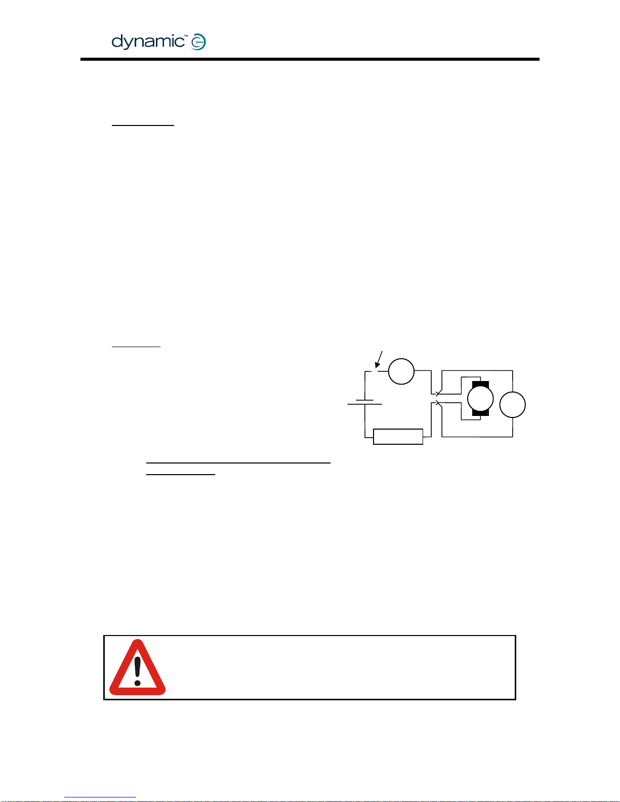
2. Measure the resistance of a motor
Tools needed
• One 12V battery (capacity 20 Ah or more),
or a 12V DC power supply that can deliver at least 20A
• A resistance of approximately 1 Ohm - 100 Watt,
for example:
o A high power resistor
o Extra motors in series
o 50m/150ft of 1 mm
2
or AWG18 wire (for example 25m/75ft AC copper
extension cord or copper speaker wire that is shorted at one end)
o 75m/250 ft of AWG16 wire (for exam ple a 37m/125 ft AC copper extension
cord or copper speaker wire that is shorted at one end)
• One Voltage meter
• One A mpere meter that can measure at least 20A
(for example: a clamp meter)
• The mo tor
Procedure
Do not connect yet
Lock the
motor
1. Lock the motor so that the shaft
can not turn (for example with
the parkbrake). If you use additional
motors as resistors, lock those too.
A
GBK60348
: Issue 1 – October 2007
36
2. Connect the motor, the Volt meter, the
Ampere meter, the resistor and the battery
together as shown in the schematic.
Do NOT connect the positive terminal of
the battery yet
.
3. Put the Voltage meter a nd the Ampere meter in a position where you can
read them both at the same time
4. Set the range of the Voltme ter to 10V and the range of the Ampere meter to 20A
5. Perform the measurement
a. Connect the positive terminal of the battery and wait until the readings on
the meters are stable (typically one to three seconds)
b. Quickly read the value on the Voltage meter and the Ampere meter
c. Disconnect the battery immediately after you have read the meters.
Warning:
Try to disconnect the battery within 5 seconds to make sure that the
motor or the resistor does not heat up too much.
+
M
V
R
12V
1Ω, 100W
Include the motor cables (but not the
connector) in the Voltage measurement
Page 37

MT
6. If the current that you have measured is less than 8A, either use a 24V battery
or use half the resistor value and repeat the measurement. For a good
measurement the current should be between 8A and 20A.
7. The motor resistance is the voltage divided by the current:
Motor resistance =
Measured Voltage at the motor connector
Measured Current
8. Lock the motor shaft in a different position and repeat the procedure from
step 5. Measure the resistance for at least five different positions of the shaft to
reduce the chance that the brushes do not mak e good contact with the
rotor.
When you have used extra motors as resistance, you do not have to change
the shaft position of those motors as well.
Use the lowest measured resistance and decrease it by 20%
37
9.
to compensate
for temperature variations and age variations. Multiply the found resistance by
1000 (for milliohm) and program this value into the Load Compensation
parameter with either the HHP or the Wizard.
10. Test the powerchair behaviour with this Load Compensation setting. Drive up
a slope or a sidewalk edge. If Load Compensation has the correct value:
• The chair only slightly slows down when it goes up the slope/edge
• The chair only slightly changes direction when it goes up the slope/edge.
Notes:
1. If the motor is connected to the battery longer than 5 seconds, the
motor becomes warm. If the motor is warm, let the motor cool down
before you do the next measurement.
2. A new motor usually has a higher motor resistance than a motor that
has been used for some time, because the motor brushes that are
inside the motor do not make optimal contact until they are "worn
in". If possible, perform this procedure when the motor has been
used for several hours.
3. Extremely low ambient temperatures can affect the motor
resistance. If the powerchair has been in the garage on a cold day,
the response when it is turned on can be a bit rough. This rough
behaviour stops as soon as the motor heats up. If the powerchair will
be used in extremely low ambient temperatures decrease Load
Compensation accordingly.
4. If the found motor resistance is 100 mΩ or less, perform the same
measurements with a warm motor. Use the lowest value of all
measurements.
Page 38

3. Determine the motor resistance by looking at the powerchair behaviour
1
2
3
Tools needed
1. A powerchair with a DX System fitted
2. A Hand Held Programmer (HHP)
3. A bump or a sidewalk edge that you can
drive up to
Procedure
Summary
• Set Load Compensation to a lo w value.
• Drive the powerchair into a Load and increase the motor resistance value
until the powerchair does not slow down.
Step by step
1. Turn the DX System ON
2. Position the powerchair in front of the edge
3. Connect the HHP to the DX Master Remote
GBK60348
: Issue 1 – October 2007
38
4. Enter Technician Mode (see section
7.1.1.1, 'HHP Technician Mode')
5. Press NEXT
Technician mode
Master JS Module
JOYSTICK CALIBRATION
EXIT YES NEXT
6. Press YES 7. Press NEXT
8. Press DOWN or UP to set the motor resistance to 20 milliohms
9. Push the joystick slightly f orward to drive
at a VERY LOW SPEED
10. Keep the joystick in exactly the same
position all t h e time
VIEW/EDIT POWER MOD
Load compensation
19 milliohms
EXIT NEXT UP DOWN
VIEW/EDIT POWER MOD
Load compensation
99 milliohms
EXIT NEXT UP DOWN
** MAIN MENU **
View or Edit Power
Module ? (Tech only)
NEXT YES
VIEW/EDIT POWER MOD
Veer compensation
RIGHT 0 %
EXIT NEXT LEFT RIGHT
SLOW
Page 39
11. The chair will probably stop when you arrive
at the edge, but still k e ep the joys tick
in exactly the same position.
Press UP
12. Press the UP button on the HHP until you
can feel that the front wheels try to pull up the
edge. Every time you press UP you will
feel this more.
13. Press “UP” SLOWLY until the chair smoothly
climbs over the edge with the joystick still in
exactly the same position as in step 11.
14. Turn the powerchair around and drive
to the location of step 1
15. Push the joystick forward to go over the
edge. If load compensation has the
correct value, the chair will not slow down
much, it will go smoothly over the edge.
VIEW/EDIT POWER MOD
Load compensation
80 milliohms
EXIT NEXT UP DOWN
16. Press EXIT to save the motor resistance
17. Turn the DX System OFF
18. Disconnect the HHP.
Notes:
1. This test procedure causes the motor to become hot. For this reason
the resulting value for Load Compensation is too high. Reduce Load
Compensation by 20% to make sure that the powerchair is not
uncomfortable to drive when the motor is cold.
2. A new motor usually has a higher motor resistance than a motor
that has been used for some time, because the motor brushes that
are inside the motor do not make optimal contact until they are
"worn in". If possible, perform this procedure when the motor has
been used for several hours.
Optimum Load Compensation.
Chair responsive AND smooth
Nervous
Uncontrollable
Aim for this point: 20% back
from the top of the hill
Unresponsive
Performance
Load Compensation
Page 40

4.3.2.4 Temp Dependent Load Comp
GBK60348
: Issue 1 – October 2007
40
Parameter Possible Values Default Rev HHP Lite Std Adv
No / Yes No -,A -
Temp Dependent Load Comp
Temperature Dependent Load Compensation calculates the correct
Load
Compensation
values for different temperatures of the Power Module. This will make
sure that Load Compensation does not become too high when the Power Module is
cold, or too low when the Power Module is hot.
4.3.2.5 Veer Compensation
Parameter Possible Values Default Rev HHP Lite Std Adv
Veer Compensation -10 - +10 % 0 % -,A
If the two motors of the powerchair do not perform exactly the same, the chair will
not drive in a straight line. The chair wi ll slightly change its direction (veer) when it
drives forward.
Veer Compensation calculates how much the chair must correct its direction to go in
a straight line.
Veer
Actual
direction
Veer
Compensation
Intended
direction
Actual
direction
Veer
The chair does not drive straight when the
performance of the two motors is not equal
The chair now drives straight because Veer
Compensation corrects the direction
Notes:
1. Adjust this parameter every time a motor is replaced.
2. Other factors than motor performance can cause chair veer, for
example bent frames, flat tyres or faulty castor wheels. Correct
these problems at the source, do not use Veer Compensation.
3. Do not use Veer Compensation to compensate for out-of-centre
joystick deflection by the user.
Page 41

MT
Adjusting Veer compensation with the HHP
1. Turn the DX System ON
2. Connect the HHP to the DX Master Remote
41
3. Enter Technician Mode (see section
7.1.1.1: HHP Technician Mode)
4. Press NEXT 5. Press YES
Technician mode
Master JS Module
JOYSTICK CALIBRATION
EXIT YES NEXT
** MAIN MENU **
View or Edit Power
Module ? (Tech only)
NEXT YES
6. Press LEFT or RIGHT until the powerchair 7. Press EXIT to save the Veer
drives in a straight line when the Compensation value
joystick is deflected forward
8. Turn the DX System OFF
9. Disconnect the HHP
4.3.2.6 Emergency Deceleration
Parameter Possible Values Default Rev HHP Lite Std Adv
Emergency Deceleration 25 - 100 % 75 % -,A -
Emergency Deceleration sets the rate at which the powerchair comes to a halt when
• a fault that requires an emergency stop occurs
• the user switches off the system while driving.
If Emergency Deceleration is set to a higher value, the powerchair will stop in a
shorter time period. The optimum value depends on the powerchair type, the
preference of the manufacturer and the regulations that apply to the country of use.
Test this parameter by switching off the system while driving.
Warning:
The powerchair can tip over or throw the user out of the chair when
this parameter is set too high.
VIEW/EDIT POWER MOD
Veer compensation
RIGHT 0 %
EXIT NEXT LEFT RIGHT
VIEW/EDIT POWER MOD
Veer compensation
RIGHT 0 %
EXIT NEXT LEFT RIGHT
Page 42

4.3.2.7 Left/Right Motor Swap
GBK60348
: Issue 1 – October 2007
42
Parameter Possible Values Default Rev HHP Lite Std Adv
Left/Right Motor Swap Normal / Swap Normal -,A -
If set to Swap, this parameter swaps the Left and Right motor outputs of the Power
Module. Swapping the motor outputs allows the cabling between the Power Module
and the motors to be optimised for particular Power Module mounting orientations.
Parameter value Normal Swap
Left motor M1 Left motor M2
Motor connection
Right moto r M2 Righ t motor M1
Note:
Most Fault messages and Diagnostic messages ignore the value of
this parameter. Left Motor/Parkbrake fault is always the
motor/parkbrake connected to M1, Right Motor/Parkbrake fault is
always the motor/parkbrake connected to M2.
4.3.2.8 Motor Invert
Parameter Possible Values Default Rev HHP Lite Std Adv
Left Motor Invert No / Yes No -,A -
Right Motor Invert No / Yes No -,A -
If these par ameters ar e s et to Yes, the y swap the polarity of the motor connector (see
section
2.3.2, Motor co nnections): '+' will become '–' and '–' will become '+'.
Note:
1. If you invert only one of the two motors, the performance of the
DX System will be reduced. This situation is not recommended for
long term use.
2. The Left Motor can refer to M1 or M2, dependent on the
Left / Right Motor Swap setting.
Page 43

MT
4.3.2.9 Motor Stall
43
Parameter Possible Values Default Rev HHP Lite Std Adv
Stall Timeout No / Yes Yes -,A -
Stall Time 5 – 50 s 15 s -,A -
If the joystick is deflected but th e powerchair can not drive because
• It is on a slope that is too steep
• I t tr ies to climb u p a curb that is to o high
• It is trapped
the maximum current (as set by the
Current Limit parameter, see section 4.3.2.1) will
flow through the motors continuously, because the motors are still trying to drive. This
situation is called motor stalling .
Motor stalling can cause motor damage when the motor becomes too hot. To
prevent motor damage, Stall Timeout disables drive after Stall Time seconds of
maximum continuous current.
If a stall timeout has occurred, the powerchair will not drive and Flash Code 11
(see
9.6) will be displayed on the System Status LED of the DX Master Remote.
To reset the system, switch it off and switch it back on again.
Note:
Some safety standards specify a particular Stall Time.
4.3.2.11 Motor Continuity Test
Parameter Possible Values Default Rev HHP Lite Std Adv
Motor Continuity Test No / Yes Yes -,A -
Every time before the powerchair starts to drive, Motor Continuity Test checks that the
motors connections are not loose.
Always set this parameter to 'Yes', except if motor faults occur because
• the motor brushes frequently lose contact after the motor has stopped
• the motor resistance is higher than approximately 1 Ω, which causes the
Power Module to think that the motor has an open circuit.
Page 44

4.3.2.12 Maximum Motor Volts
GBK60348
: Issue 1 – October 2007
44
Parameter Possible Values Default Rev HHP Lite Std Adv
Maximum Motor Volts 24 – 30 V 26 V -,A -
Maximum Motor Volts sets the maximum voltage that the Power Module will apply to
the motor.
Note:
If local regulations require that the powerchair speed is limited to a
specific value, use this parameter to set a speed limit for a particular
chair type (for specific motors and a specific wheel diameter).
If the momentary battery voltage is less than the programmed Maximum Motor Volts
value (for example when the battery is almost empty), then the battery vol tage i tse lf
is the maximum applied voltage at 100% speed demand.
See also section
5.3.1: Speed and acceleration principles.
4.3.2.13 Input Demand Scaler
Parameter Possible Values Default Rev HHP Lite Std Adv
Input Demand Scaler 50 – 100 % 95 % -,A -
The Input Demand Scaler scales down the Speed Demand that the Power Module
receives from the UCM (see also section
5.3.1: Speed and acceleration principles).
This makes sure that the powerchair does not slow down when it changes direction.
To adjust the direction of the powerchair when the chair travels forward, the Power
Module speeds up one wheel while it keeps the speed of the other wheel constant.
The Power Module can only speed up one wheel if that wheel is not turning at
maximum speed already.
If both wheels are turning at maximum speed, the Power Module must slow down one
wheel to change direction. This slows down the whole powerchair during the turn,
which can be annoying.
An Input Demand Scaler value of 95% limits the maximum speed of the chair to 95% of
the maximum achievable speed during normal driving. This leaves 5% of the
maximum wheel speed reserved for turning.
The Input Demand Scaler is also useful to further slow down a chair when the
minimum speed settings of the Drive Profi les are still too fast.
Page 45

MT
4.3.3 Park Brakes
4.3.3.1 Park Brake
45
Parameter Possible Values Default Rev HHP Lite Std Adv
Park Brake Single / Dual Dual -,A -
Single – Only parkbrake output M1 is active. Do not use parkbrake output M2.
Dual – Parkbrake output M1 and M2 are both active.
See section
2.4.2: Parkbrake configurations for more information on how to connect
the parkbrakes.
4.3.3.2 Brake / Bridge Off Delay
Parameter Possible Values Default Rev HHP Lite Std Adv
Brake / Bridge Off Delay 100 – 1000 ms 500 ms -,A -
The Power Module uses the motors to brake the powerchair during the time that the
parkbrakes have been de-energised but have not engaged mechanically. This
braking method is called active motor braking.
When the parkbrakes have been de-energised, the Power Module applies active
motor bra king for the time defined by the Brake / Bridge Off Delay parameter. After
this time the Power Module will switch off the motors.
The correct value of this parameter is dependent o n the mechani c s o f the parkbrake
that is used on the chair.
Warning:
Make sure that the Brake / Bridge Off Delay value is greater than the
time it takes for the parkbrakes to mechanically engage when they
have been electrically de-energised. The parkbrakes must engage
before the motors turn off, or the powerchair will roll away.
See also section
2.4.5: Parkbrake operation and programming.
4.3.3.3 Test Park Brake Driving
Parameter Possible Values Default Rev HHP Lite Std Adv
Test Park Brake Driving No / Yes Yes A -
Yes – The park brakes are periodically checked for open-circuit while the chair is
driving. Some parkbrakes produce a noise during this test, which can annoy
the user.
No – The park brakes are
not checked for open-circuit while the chair is driving,
only
before the chair starts to drive.
The parkbrake short-circuit test it is not affected by the value of this parameter.
The short-circuit test will still be performed while driving.
Page 46

GBK60348
: Issue 1 – October 2007
46
4.3.4 Battery
4.3.4.1 Battery Guess
Parameter Possible Values Default Rev HHP Lite Std Adv
Battery Guess Maximum 24.2 – 28.8 V 25 V -,A -
Battery Guess Minimum 22.3 – 26.2 V 22.7 V -,A -
Battery Guess Recover 0 – 30 decimal 15 dec -,A -
These battery parameters can optimise the accuracy of the Battery Gauge.
Battery Guess Maximum is the voltage at which the DX System thinks that the battery
is completely full. The Battery Gauge will show 100% battery capacity at this voltage.
Battery Guess Minimum is the voltage at which the DX System thinks that the battery is
completely empty. The Battery Gauge will show 0% battery capacity at this voltage.
Battery Guess Recover is the maximum voltage drop of the battery during driving. If
the powerchair stops driving, the battery voltage will again increase to its original
level. This increase in voltage does not mean the battery has been charged, just that
the powerchair has stopped driving. Battery Guess Recover is the maximum voltage
increase expected of the battery after driving when no charging has occurred. If the
battery voltage rises by more than this value while the DX System is off, the Battery
Gauge will be updated.
Normally these parameters should be left at the factory pre-set values.
4.3.4.2 Voltmeter Battery Gauge
Parameter Possible Values Default Rev HHP Lite Std Adv
Voltmeter Battery Gauge No / Yes No A -
No – The Battery Gauge shows an estimate of the remaining battery capacity.
Yes – The Battery Gauge shows the battery voltage as an indication of the battery
capacity. This means that the shown value can decrease momentarily during
high load situations (for example: when driving up a slope) .
4.3.4.3 Slow Batt Time Scale Driving
Parameter Possible Values Default Rev HHP Lite Std Adv
Slow Batt Time Scale Driving No / Yes No A -
If
Voltmeter Battery Gauge (4.3.4.2) has the value 'Yes', Slow Batt Time Scale Driving
determines the responsiveness of the voltmeter battery gauge.
No – The Battery Gauge has a fast response. This can result in a nervous display
when the powerchair drives over different loads.
Yes – The Battery Gauge has a slow and stable response.
If Voltmeter Battery Gauge has the value 'No', the value of Slow Batt Time Scale Driving
is ignored.
Page 47

MT
47
4.3.4.4 Batt Gauge Ramp Rate
Parameter Possible Values Default Rev HHP Lite Std Adv
Batt Gauge Ramp Up Rate
10 – 1600 s 120 s A -
Batt Gauge Ramp Down Rate
10 – 1600 s 90 s A -
These parameters help to smooth out changes in the battery voltage caused by short
temporary charging or a temporary heavy load.
Battery Gauge Ramp Up Rate is the minimum time it takes the Battery Gauge to go
from the minimum position to the maximum position. Do not set this longer than the
time it takes to ful ly charge the batteries.
Battery Gauge Ramp Down Rate is the minimum time it tak es the Battery Gauge to go
from the maximum position to the minimum position.
4.3.4.5 Batt Gauge Threshold
Parameter Possible Values Default Rev HHP Lite Std Adv
Batt Gauge High Threshold 0.1 – 33.4 V 33.4 V A -
Batt Gauge Failing Threshold 0.1 – 6.6 V 0.1 V A -
If the batteries are being charged for only a shor t peri od of time, the battery voltage
will still rise as long as no large current is drawn from the batteries (for example: when
the DX system is switched on after charging). This can mislead the battery gauge into
thinking that the batteries are full, when in fact, they are not.
To make sure that the battery gauge does not show the wrong information, the
battery level information is saved when the DX System is turned off. When the System
is turned on again, the new level of the battery is compared to the old level. If the
new level is very different from the old level, the old level is displayed on the battery
gauge, unless the current battery level is higher than Batt Gauge Failing Threshold, or
lower than Batt Gauge High Threshold.
4.3.4.6 High Voltage parameters
Parameter Possible Values Default Rev HHP Lite Std Adv
High Voltage Warning No / Yes Yes A -
High Voltage Rollback No / Yes No A -
High Voltage Threshold 28 / 30 V 28 V A -
If High Voltage Warning has the value 'Yes', and the voltage of the batteries rises
above the value of High Voltage Threshold, the battery gauge will flash to warn the
user that the batteries are being overcharged.
High Voltage Rollback gradually decreases the maximum speed of the powerchair
when the battery voltage rises above 30 Volt. This is especially useful when the user is
driving downhill. See also section
2.2.4.3: High Voltage Rollback.
Page 48

4.3.4.7 Temperature Rollback
GBK60348
: Issue 1 – October 2007
48
Parameter Possible Values Default Rev HHP Lite Std Adv
40 – 75 °C 50 °C -,A -
Temperature Rollback Minimum
50 – 85 °C 70 °C -,A -
Temperature Rollback Maximum
To protect the Power Module from overheating, a thermal roll-back algorithm
reduces the output c u r rent when the Power Mo dule beco m e s too hot.
Temperature Rollback Minimum is the temperature at which the thermal
roll-back starts.
Temperature Rollback Maximum is the temperature at which the thermal
roll-back limits the output current to zero.
Maximum Current
Temp.
Temp
Rollback
Minimum
Limit
(
4.3.2.1
)
Temp
Rollback
Maximum
4.3.4.8 Halve Turning Gain
Parameter Possible Values Default Rev HHP Lite Std Adv
Halve Turning Gain No / Yes No A -
Halve Turning Gain halves the values of the
Turning Speed @ Maximum (5.3.7.9) and
the
Turning Acceleration (5.3.7.11) parameters for every Drive Profile (for more
information on
Drive Profiles see 5.3.2).
This allows lower turning speeds and acceleration without a loss of resolution.
Enabling Halve Turning Gain is particularly useful for high speed chairs and Front
Wheel Drive chairs where low turning speed s are required.
See also
Non-Linear Turn (section 5.3.7.13).
Note:
Wizard 5 uses the value of the Halve Turning Gain parameter to
determine the Power Module Revision (Rev –, or Rev A). Set this
parameter to Yes if you want to use the Rev A parameters. If the
Halve Turning Gain parameter is set to No, the Wizard will assume that
the program is meant for a "Rev–" Power Module, and will return all
Rev A parameters to their default values before it writes the
parameters to the Power Module.
Page 49

MT
5 The DX Master Remote
Warning:
This manual describes a generic DX System and Master Remote use.
It must be read together with the installation manual of the actual
Master Remote that will be installed on the powerchair.
5.1 Introduction
The Master Remote is the central building block in a DX System. Every DX System must
have one, and only one Master Remote.
The DX Master Remote
• Acts as the primary user interface
o Has the system on/off switch
o Reads user commands (joystick movement, button pushes, switches)
o Communicates these commands to the applicable DX Modules
through the DX BUS
o Displays the system status to the user via the System Status LED
• Controls the status of the DX System
Drive Profiles
49
• Stores and controls up to six
(see section 5.3.2)
• Backs up all system parameters
• Restores system parameters if a module has been replaced (see section 7.3)
• Provides a DX System programming socket for the HHP or the Wizard.
A range of Master Remotes is available for different applications and end-user
requirements.
The Master Remote is fully programmable to suit a wide range of powerchair types
and user needs. Correct installation and programming are essential to ensure
optimum performance and safety.
A Master Remote consists of two major sub-components:
• the User Control Module (UCM)
• the Physical User Interface.
UCM
Display
controller
DX BUS
Switches
Display
Joystick
Direction
Speed
Page 50

GBK60348
: Issue 1 – October 2007
50
5.1.1 The User Control Module (UCM)
The UCM is the brain, or the main computer, of the DX System. The UCM is built into
every Master Remote.
The UCM is responsible for
• System wake-up and shutdown
(the UCM is connected to the system on/off switch)
• System safety, diagnostics, status and fault codes
• System backup and restore
• DX BUS testing and operation
• Reading the input commands (desired speed and direction, actuator position
switches) from the Physical User Interface and all external remotes and
modules
• Generating the output commands (calculated speed and direction, actuator
control) and sending these over the DX BUS to the Power Module and fitted
auxiliary modules
• all system drive algorithms
• all programmable system parameters.
• RS232 serial communication with programming tools (HHP or Wizard)
The UCM has had several software revisions:
• - (dash)
• A
• C
The available parameters and their meaning are slightly different between software
versions. See the programming section for a list of all parameters.
5.1.2 The physical user interface
The physi cal user interface translates the physical inputs (butto ns, joystick) into
electrical signals it sends to the UCM. It also translate s the electrical outputs of the
UCM to visible or audible user signals (LEDs, displays, the horn).
The Physical User Interface always consists of
• the housing
• the System Status LED
And optionally
• a joystick
• a display
• a battery gauge
• a battery charger socket
• buttons and knobs
• connectors for external switches
Most Master Remotes have their own user input device in the form of a joystick, but
this is not always the case. For example: the G91 do es not have a joystick, it depends
on either a Secondary Remote or a set of switches to obtain direction and speed
commands.
Page 51

MT
Most Master Remotes have their own display with battery gauge and system status
information. Some Master Remotes however, such as the chin remote and the tray
remote, do not have their own display, they only have a System Status LED.
5.2 Available Master Remotes
5.2.1 Master Remotes with joystick
51
Master Remote Application
Advanced driving
Advanced seating
Highly customisable
Switched control available
Joystick only menu control available
DX-REMG90A
Environmental control
DX-REMG90T
G90A : two sockets to connect external switches
G90T : two t oggle switches
Advanced Driving
Seating and lighting
All actuators directly accessible from keypad
DX-REM34
Dolphin Remote
Advanced Driving
Seating and lighting
DX-REM41
All actuators directly accessible from keypad
DX-REM41S
Dolphin Tray Remote
Chin control
Drive only: Joystick, on/off switch, Speedpot
No display
DX-REM32
No battery charger socket, only a programming socket
Chin Remote
Drive only: Joystick, on/off switch, Speedpot
No display
No battery charger socket, only a programming socket
DX-REM35
Tray Remote
Master Remote joystick for attendant use.
Switch to take control / release control
DX-ACU3
Can control chair, charging and actuators.
Attendant Control
Unit
Optionally use Secondary Remote for user control.
Page 52

5.2.2 Master Remotes without joystick
GBK60348
: Issue 1 – October 2007
52
Master Remote Application
Mounting close to the face of the user to optimise visibility
Advanced driving, seating, lighting and environmental control
3-quadrant RIM, switched or proportional
Optional j oystick control with Secondary Remote
Bi-directional actuator control
DX-REMG91
Highly customisable
DX-REMG91S
Accessor y Shortcut Key gi ves access to the last used function
G91S provides single switch scanning
Switched Drive (4 directions) + one switched On/Off control
Optional joystick/attendant control with Secondary Remot e
DX-MASTERSW
Switch Interface
Advanced menu-driven driving and environmental control
Joystick operation with Secondary Remote
Joystick-only control
DX-SCR
Joystick + Mode button control
Specialty Controls
Single Switch Scanning control
Page 53

MT
5.3 Programmable parameters
5.3.1 Speed and acceleration principles
M
Maximum
Motor
Volts
Accel/Decel
Speed Demand
0 – 100 %
Joystick
deflection
0-100 %
Power
Module
UCM
Speed Limiting Options
Input Demand Scaler
Max Demand
Spd Limit
Speed Pot
Speed @ Max
5.3.1.1 Speed Demand
When the user deflects the joystick or presses a dr ive control switch, the UCM (see
section
5.1.1) converts the Joystick Deflection value into a Speed Demand value. The
UCM then sends this Speed Demand value to the Power Module. The Speed Demand
value is given as a percentage of the mechanical top speed of the powerchair.
The actual achievable mechanical top speed (in km/h) of any particular powerchair
depends on factors like
• the wheel size
• the motors
• the gear used
• the available battery voltage
(batteries that are almost empty have a lower maximum output voltage).
The mechanically achievable top speed varies greatly between powerchair models.
For this reason the Speed Demand value is given as a
percentage of that
mechanical top speed.
For example:
• A chair that has a mechanical top speed of 12 km/h will drive at
approximately 6 km/h when the Speed Demand is 50%*.
• A chair that has a mechanical top speed of 8 km/h will drive at approximately
6 km/h when the Speed Demand is 75%*.
*When the Input Demand Scaler and the Maximum Motor Volts parameters are both set at their maximum
value. See next section for more details.
53
Page 54

5.3.1.2 Speed limiting options
The DX System offers many options that limit the available Sp eed Demand range to
suit safety requirements as well as the preferences of the user. These options can be
grouped into five categories:
• the Maximum Motor Volts parameter
• the Input Demand Scaler parameter
• the Speed @ Maximum parameter
• the Speed Pot function
• the Speed Limit function.
100%
100%
100%
Speed @
Maximum
Speed @
Minimum
Speed Pot
(0-100%)
Speed Limit
(0-100%)
100%
Chair physical top speed*
Zero s
p
eed
100%
PM Input Demand Scaler
100%
Chair speed @
100% Joystick
Deflection
Joystick
This line is pushed down
by the dynamic speed
limiting function that has the
lowest momentary value
(in this example Speed Pot)
Static speed limit
Dynamic speed
limiting functions
momentary value
* The 'Chair physical top speed' is limited by either the available battery voltage or the
Maximum Motor Volts parameter, whichever has the lowest momentary value.
The
Maximum Motor Volts
GBK60348
: Issue 1 – October 2007
54
parameter (4.3.2.12) sets the maximum Voltage tha t the
Power Module will apply to the motor. The powerchair manufacturer can use this
parameter to limit the 'Chair physical top speed' to a calculated speed limit for a
particular chair type (for specific motors and a specific wheel diameter).
The
Input Demand Scaler parameter (4.3.2.13) allows the Power Module to scale
down the Speed Demand that the UCM requir es. A reduced Speed Demand creates
extra steering headroom if a turn is requested at full speed (because steering is
normally done differentially, with one wheel turning faster than the other one).
The
Speed @ Maximum parameter can be adjusted by the dealer to set a maximum
UCM Speed Demand value for the chair, suitable for a specific user. Every Drive
Profile has its own Speed @ Maximum setting for forward, reverse and turning to allow
different speed limits for different circumstances (indoors, outdoors).
For more information on Drive Profiles, see section
5.3.2.
Page 55

MT
55
The
Speed Pot function is adjusted by the user to decrease the maximum speed of
the chair according to his/her needs at the time. The adjustable value has a range of
0-100%. A Speed Pot value of 100% means that the maximum speed is equal to the
Speed @ Maximum parameter. A Speed Pot value of 0% means that the maximum
speed is equal to the Speed @ Minimum parameter. Therefore Speed @ Minimum
actually means: The Maximum Speed when the Speed Pot function has the value
zero.
The Speed Pot function gets its input from a group of parameters:
• A mechanical analogue speed pot (0-100%)
• A digital speed pot on the Master Remote (0-100%)
• The
Chair Speed parameter (5.3.9.1) on the HHP (0-10, converted to 0-100%)
• The DX BUS Speed Pot parameter (0-100%). Any DX Module can take control
of this parameter via the DX BUS.
The actual output value of the Speed Pot func tion will be the lowest of all the
parameters above.
The
Speed Limit function allows DX Modules to limit the maximum speed when
necessary. For example: when the seat is raised, the speed of the chair must be
limited. The adjustable range (0-100%) is a percentage of the Speed @ Maximum
parameter.
The Speed Limit function gets its input from a group of parameters:
•
CLAM Slowdown (5.3.10.1)
• The DX BUS Slow parameter. Any DX Module can take control of this
parameter via the DX BUS.
• Maximum Demand Indicator (MDI). The Power Module indicates to the UCM
when it cannot fulfil the Speed Demand, for example when the user tries to go
up a slope that is too steep, or when the battery voltage would become
higher than the Maximum Motor Volts parameter (
4.3.2.12).
• Internal stability algorithms that momentarily limit the speed for safety reasons.
The actual output value of the Speed Limi t function will be the lowest of all the
parameters above.
Page 56

5.3.1.3 Acceleration and deceleration
Acceleration is the rate at which the speed increases when the joystick is pushed out
of the centre position.
GBK60348
: Issue 1 – October 2007
56
SPEED
TIME
The acceleration of the powerchair can be adjusted with the
Forward Acceleration (5.3.7.3), the Reverse Acceleration (5.3.7.7) and the
Turning Acceleration (5.3.7.11) parameters.
Deceleration is the rate at which the speed decreases after the joystick has been
returned to the centre position.
Too high
• Too sensitive
• Jerky
Too low
• Unresponsive
• Long delays
Good
• Smooth
• Dependent on user
and environment
SPEED
Too low
• Unresponsive
• Braking distance
too long
The deceleration of the powerchair can be adjusted with the
Forward Deceleration (5.3.7.4), the Reverse Deceleration (5.3.7.8) and the
Turning Deceleration (5.3.7.12) parameters.
Note:
The UCM applies the acceleration and deceleration algorithms to
the Speed Demand value after the speed limiting functions.
Warning:
Too high or too low acceleration / deceleration settings can result in
potentially dangerous chair behaviour and lead to injury.
TIME
Too high
• Rough
• Can eject the
user from the
chair
Good
• Smooth
• Dependent on user
and environment
Page 57

MT
Damping Point
When the powerchair almost reaches the desired spe ed , the
acceleration / deceleration rate (that initially is given by the applicable
acceleration / deceleration parameter of the previous page) is slowly decreased to
zero. This prevents a sudden change in acceleration once the desired speed is
reached.
Use the Speed Damping and Turn Damping parameters (see
5.3.7.16) to adjust the
point where the damping starts.
0%: No damping
100%: Maximum damping.
Damping point
Time
Speed
57
The
Min To Max Decel Ratio parameter (section 5.3.7.17) defines the slope at the end
of the curve before the final speed is reached, as a percentage of the
acceleration / deceleration slope before damping has started.
4%: The end acceleration / deceleration is 4% of the acceleration / deceleration
before damping, which gives a very smooth curve.
100%: The end acceleration / deceleration is 100% of the acceleration / deceleration
before damping, which effectively results in no damping at all.
Soft-Start Acceleration
The Damping Point only affects the end of the acceleration curve in most cases. To
provide a smooth start from a standstill when the joystick is suddenly deflected to
100% (for example with a switched joystick) use
Soft-Start Acceleration (see 5.3.9.2) in
combination with the
Soft-Start Time parameter (see 5.3.8.6).
100 %
Damping point
4 % Ratio
Damping point
100 % Ratio
Time Time
4 %
100 %
100 %
100 %
Speed
Speed
Soft-Start Time
Time
Speed
Page 58

5.3.2 Drive Profiles
5.3.2.1 The principle
A Drive Profile is a set of parameters which
• define the maximum speed and the responsiveness (acceleration and
deceleration) of the chair
• select the desired input source, such as the joystick of the Master Remote,
a secondary joystick or external switches.
Drive Profiles can provide access to multiple control sources, define indoor and
outdoor driving modes or simply provide a digital speed pot by programming a range
of preset maximum speeds.
The DX system can store up to 6 Drive Profiles. Each Drive Profile can be
independently customised to provide varying levels of speed and responsiveness.
Some of the Drive Profile parameters as they appear in the Wizard
Dependent on the features of the Master Remote in us e and its programming, the
user can choose Drive Profile 1-5 with
• the Drive Profile selection buttons on the Master Remote
• the joystick on the Master Remote or the Secondary Remote
GBK60348
: Issue 1 – October 2007
58
• the ARC buttons or switches (see
6.6.3.4)
• external Drive Profile selection switches, if fitted.
Drive Profile 6 is intended for use with an Attendant Control Unit
(ACU), and is called the ACU profile. Drive Profile 6 is automatically
selected when an ACU that is in the 'Attendant Mode' is connected
to the DX System. When the ACU is disconn ected, or when it returns
to the 'User Mode', the powerchair automatically returns to the
Drive Profile that was selected when the ACU became active (see
the ACU User Manual for more details).
DX-ACU1
Page 59

MT
5.3.2.2 Drive Profile 0
Drive Profile 0 has all parameters set the same as Drive Profile 1, but prevents the
powerchair from driving. This is a safety feature required by some regulatory
authorities to prevent a sudden change in speed when progressing from Drive
Profile 1 (normally the slowest), down to Drive Profile 5 (normally the fastest) when
Wrap Profiles
59
is enabled (see section 5.3.8.2).
Drive Profile 0 can be used for its ability to inhibit driving, particularly when used for
Actuator Mode (when actuators are enabled).
Enable Drive Profile 0 with the
Allow Non-Driving Profile parameter (5.3.8.4).
5.3.2.3 Speed setting recommendations
Each Drive Profile has its own Maximum Speed, Acceleration and Deceleration
settings for forward, reverse and turning. These settings can be adjusted so that the
different Drive Profiles either
• act as a digital Speed Pot, or
• cater for the different needs in different environments,
for example indoors or outdoors.
It is common practice to program Drive Profile 1 as the slowest profile and
Drive Profile 5 as the fastest profile.
Programming Drive Profiles as a digital Speed Pot
• Forward speed should have a large linear range between drive profiles
• Reverse and turning speed should change only slightly for faster drive profiles
• Grip (see
5.3.7.15) should be decreased for faster drive profiles to maintain
chair stability.
Drive
Profile
Maximum
Forward
Speed
Maximum
Reverse
Speed
Maximum Grip
Turning
Speed
(5.3.7.15)
Turning
Speed
100%
Reverse
Speed
Forward
Speed
100%
100%
1 20 % 20 % 20 % 100%
2 40 % 20 % 20 % 85%
3 60 % 25 % 25 % 70%
4 80 % 30 % 30 % 55%
5 100 % 30 % 35 % 40%
Drive
Profile
Minimum
Forward
Speed
Minimum
Reverse
Speed
Minimum
Turning
Speed
All 5 % 5 % 5 % -
Page 60

Programming Drive Profiles for different environments
• Turning speed can be higher for indoor drive profiles, because
fast turning at low speed can be helpful indoors to drive around objects.
• Fast turning at high forward speed can be dangerous, so the fast outdoor
drive profile should have a lower turning speed.
GBK60348
: Issue 1 – October 2007
60
Warning:
The recommended parameter values are a guideline only. Testing is
required to verify suitability for individual chair designs and user
preference.
Note:
Adjust the
Load Compensation parameter (4.3.2.3 ) to the correct
motor resistance value before you program the Drive Profile speed
settings. Load Compensation controls the behaviour of the motor.
The behaviour of the motor changes the performance of all speed
and acceleration parameters. If you adjust the Load Compensation
parameter after you have set the speed parameters, you will
probably have to re-adjust many speed parameters again.
5.3.2.4 Single Drive Profile mode
Normally Drive Profiles are used to customise a chair to the comfort and driving habits
of one user. If a chair is frequently shared between users,
Single Profile Mode (see
5.3.10.4) in combination with Chair Speed Enable (see 5.3.10.3) can be useful.
Single Drive Profile mode makes it easy to quickly adapt a chair to different users or
situations without the need for extensive programming. When the HHP is plugged in,
the therapist or carer can easily adjust the overall Chair Speed and select the desired
Drive Profile (such as the Drive Profile for user X, or the Drive Profile for indoor use).
The user can not change the Drive Profile, because the Profile Select buttons work as
a digital Speed Pot for the Drive Profile that is currently active, t hey do not change
the active Profile. This makes sure that the user does not accidentally change the
Drive Profile to the Profile of another user, or the fast outdoor Profile when indoors.
Drive
Profile
Type
Maximum
Forward
Speed
Maximum Maximum
Grip
Reverse Turning
(see 5.3.7.15)
Speed Speed
1 Home 20 % 20 % 20 % 80 %
2 Mall 40 % 20 % 40 % 40 %
3 Outdoor wet 60 % 30 % 20 % 25 %
4 Outdoor dry 60 % 30 % 20 % 80 %
5 Outdoor fast 100 % 30 % 10 % 80 %
CHAIR SPEED
Min ########### Max
NEXT DOWN UP
The first HHP screen changes the
overall Chair Speed
RESPONSE
1
NEXT DOWN UP
The second HHP screen changes
the Drive Profile (called Response)
Page 61

MT
5.3.3 Two or more joysticks: choosing the joystick source
Every Drive Profile has its own external joystick setting.
Select the joystick to use for each Drive Profile wi th the
Joystick Source parameter
(see section
5.3.8.7).
This parameter can be adjusted with the HHP and the Wizard.
5.3.4 Reducing the movement to operate the joystick
Normally a DX powerchair will reach full speed only when the joystick is pushed as far
as it can mechanically go (for example when it hits the restrictor plate).
For some users it may be difficult or impossible to move the joystick to the end point.
In these cases the Short Throw Travel parameter (
5.3.7.14) can reduce the amount of
deflection (and therefore pressure) required to achi eve full speed. The dealer or
therapist can adjust this parameter to suit the physical abilities of specific users.
For actuator operation, the Joystick Switch Threshold parameter (
5.3.10.16) can
reduce the amount of deflection that is needed before the switch function is
activated.
Warning:
When you adjust Short Throw Travel, use Short Throw Shape to make
sure that the user can not request full forward speed and full turn
speed at the same time. See section
5.3.7.14 for more details.
5.3.5 Chair stability
The DX System has several options to increase the stability of a powerchair.
61
• The
Grip parameter (see 5.3.7.15) defines the physical grip of the powerchair.
Set this parameter low for Drive Profiles that are used on slippery surfaces.
• The
Chair Stability Parameters (see 5.3.7.18) are useful to make sure that the
powerchair does not lose control when it tries to make a turn at high speed.
• The
Steering stability parameters (see 5.3.7.19) can help the user to steer
straight and to prevent steering delays when the chair is driving at full speed.
See also section
7.4: Programming and testing a DX chair for stability.
Page 62

GBK60348
: Issue 1 – October 2007
62
5.3.6 List of parameters
Key:
Editable at this level (see sec tion 7.1.2.1: Dongle versions)
Viewable at this level
Parameter Possible Values Default Rev HHP Lite Std Adv
Drive Profiles
Forward Speed @ Maximum 10 – 100 % N/A -,A,C
Forward Speed @ Minimum 5 – 100 % 5% C
Forward Acceleration 10 – 70 % 40 % -,A,C
Forward Deceleration 15 – 100 % 60 % -,A,C
Reverse Speed @ Maximum 10 – 100 % N/A -,A,C
Reverse Speed @ Minimum 5 – 100 % 5% C
Reverse Acceleration 10 – 70 % 70 % -,A,C
Reverse Deceleration 15 – 100 % 30 % -,A,C
Turning Speed @ Maximum 20 – 100 % N/A -,A,C
Turning Speed @ Minimum 5 – 100 % 5% C
Turning Acceleration 10 – 70 % 40 % -,A,C
Turning Deceleration 15 – 100 % 70 % -,A,C
Turn Damping 10 – 100 % 40% C -
Non-Linear Turn No / Yes No C -
Short Throw Shape 100 – 200 % 200 % C -
Short Throw Travel 100 – 200 % 100 % C -
Grip 5 – 100 % 100% C
Damping Point 10 – 100 % 40 % -,A
Speed Damping 5 – 100 % 40 % C -
Min To Max Decel Ratio 4 – 100 % 20 % -,A,C -
Speed x Turn for Grip 5 – 100 % 100 % C -
Accel Out Of A Turn For Grip 0 – 200 % 100 % C -
Accel Into A Turn For Grip 0 – 200 % 100 % C -
Turning @ Full Speed 5 – 100 % 100 % C -
Turning Accel @ Full Speed 100 – 300 % 100 % C -
Page 63

MT
63
Parameter Possible Values Default Rev HHP Lite Std Adv
Drive Profile Options
Maximum Profile Number 1 - 5 5 -,A,C -
Wrap Profiles No / Yes Yes A,C -
Change Profile While Driving No / Yes No -,A,C -
Allow Non-Driving Profile No / Yes No -,A,C -
Sleep Timeout 1 – 60 min 5 min -,A,C -
Soft-Start Time 0 – 1000 ms 0 ms A,C -
Joystick Source (RJM) No / Yes No -,A
Joystick Source
Master
ACU
RJM
Display
ARC
ExtNV1
ExtNV2
None
Master C -
Joystick Swap
Forward / Reverse
No / Yes No A,C
General User Options
Speed Pot Scaler 20 – 100 % 100 %
-,A
-
Chair Speed 0 – 10 10
C
Soft-Start Acceleration No / Yes No A,C -
Neutral Maximum 10 – 50 % 10 % -,A,C -
Disable OONAPU Faults No / Yes No A,C -
Drive Delay After Power-up 0-10 0 s C -
Lock Enable No / Yes No -,A,C -
Sleep Mode Enable No / Yes No -,A,C -
Power-up Profile Number 1 - 7 7
C
-
Enable Joystick Wakeup No / Yes Yes C -
Page 64

GBK60348
: Issue 1 – October 2007
64
Parameter Possible Values Default Rev HHP Lite Std Adv
System Settings
CLAM Slowdown 0 – 100 % 20 %
-,A,C
-
Neutral to PB Delay 20 – 5000 ms 100 ms
-,A,C
-
Chair Speed Enable No / Yes No
C
-
Single Profile Mode No / Yes No
C
CANH Power Switch No / Yes Yes
C
-
CAN Terminator No / Yes Yes
C
-
UCM Joystick Swap
Left/Right
No / Yes No
-,A,C
-
Rotate UCM Joystick No / Yes No
C
-
ACU Enable No / Yes Yes
-,A,C
-
ACU Joystick Swap Left/Right No / Yes No
-,A,C
-
ACU has Momentary Switch No / Yes No
C
-
ACU Momentary Switch
Timeout
No / Yes Yes
C
-
RJM Enable No / Yes Yes
-,A,C
-
RJM Joystick Swap Left/Right No / Yes No
-,A,C
-
RJM has Analog Joystick No / Yes Yes
C
-
Joystick Switch Threshold 20 – 80 % 50 % C -
Page 65

MT
65
5.3.7 Drive Profiles parameters
These parameters have to be set for every Drive Profile:
Parameter Possible Values Default Rev HHP Lite Std Adv
Forward Speed @ Maximum 10 – 100 % N/A -,A,C
Forward Speed @ Minimum 5 – 100 % 5% C
Forward Acceleration 10 – 70 % 40 % -,A,C
Forward Deceleration 15 – 100 % 60 % -,A,C
Reverse Speed @ Maximum 10 – 100 % N/A -,A,C
Reverse Speed @ Minimum 5 – 100 % 5% C
Reverse Acceleration 10 – 70 % 70 % -,A,C
Reverse Deceleration 15 – 100 % 30 % -,A,C
Turning Speed @ Maximum 20 – 100 % N/A -,A,C
Turning Speed @ Minimum 5 – 100 % 5% C
Turning Acceleration 10 – 70 % 40 % -,A,C
Turning Deceleration 15 – 100 % 70 % -,A,C
Turn Damping 10 – 100 % 40% C -
Non-Linear Turn No / Yes No C -
Short Throw Shape 100 – 200 % 200 % C -
Short Throw Travel 100 – 200 % 100 % C -
Grip 5 – 100 % 100% C
Damping Point 10 – 100 % 40 % -,A
These parameters are set for all drive profiles at once:
Parameter Possible Values Default Rev HHP Lite Std Adv
Speed Damping 5 – 100 % 40 % C -
Min To Max Decel Ratio 4 – 100 % 20 % -,A,C -
Speed x Turn for Grip 5 – 100 % 100 % C -
Accel Out Of A Turn For Grip 0 – 200 % 100 % C -
Accel Into A Turn For Grip 0 – 200 % 100 % C -
Turning @ Full Speed 5 – 100 % 100 % C -
Turning Accel @ Full Speed 100 – 300 % 100 % C -
Page 66

5.3.7.1 Forward Speed @ Maximum
Parameter Possible Values Default Rev HHP Lite Std Adv
Forward Speed @ Maximum 10 – 100 % N/A -,A,C
Sets the forward speed of the powerchair when the joystick is fully deflected forward
and the Speed Pot is in its Maximum position.
This parameter must be set for every Drive Profile.
GBK60348
: Issue 1 – October 2007
66
See also section
5.3.2.3: Speed setting recommendations.
5.3.7.2 Forward Speed @ Minimum
Parameter Possible Values Default Rev HHP Lite Std Adv
Forward Speed @ Minimum 5 – 100 % 5% C
Sets the forward speed of the powerchair when the joystick is fully deflected forward
and the Speed Pot is in its Minimum position.
This parameter must be set for every Drive Profile.
This parameter partially replaces the
Speed Pot Scaler parameter (see 5.3.9.5).
See also section
5.3.2.3: Speed setting recommendations.
5.3.7.3 Forward Acceleration
Parameter Possible Values Default Rev HHP Lite Std Adv
Forward Acceleration 10 – 70 % 40 % -,A,C
Sets the rate at which the forward speed increases after the joystick has been
deflected forward. 10% results in a very slow increase, 70% results in a very quick
increase.
See also section
5.3.1.3 : Acceleration and deceleration.
5.3.7.4 Forward Deceleration
Parameter Possible Values Default Rev HHP Lite Std Adv
Forward Deceleration 15 – 100 % 60 % -,A,C
Sets the rate at which the forward speed decreases after the joystick has been
returned to the centre. 15% results in a very slow stop, 100% results in an instant stop.
See also section
5.3.1.3 : Acceleration and deceleration.
Warning:
Setting the Deceleration too low or too high can result in an unsafe
powerchair. Test thoroughly after programming to make sure that the
powerchair complies with regulatory requirements such as ISO7176
and the GMD-TND Homologation Directive R04 for maximum
allowable braking distance.
Page 67

MT
67
5.3.7.5 Reverse Speed @ Maximum
Parameter Possible Values Default Rev HHP Lite Std Adv
Reverse Speed @ Maximum 10 – 100 % N/A -,A,C
Sets the reverse speed of the powerchair when the joystick is fully deflected
backward and the Speed Pot is in its Maximum position.
This parameter must be set for every Drive Profile.
See also section
5.3.2.3: Speed setting recommendations.
5.3.7.6 Reverse Speed @ Minimum
Parameter Possible Values Default Rev HHP Lite Std Adv
Reverse Speed @ Minimum 5 – 100 % 5% C
Sets the reverse speed of the powerchair when the joystick is fully deflected
backward and the Speed Pot is in its Minimum position.
This parameter must be set for every Drive Profile.
This parameter partially replaces the
Speed Pot Scaler parameter (see 5.3.9.5).
See also section
5.3.2.3: Speed setting recommendations.
5.3.7.7 Reverse Acceleration
Parameter Possible Values Default Rev HHP Lite Std Adv
Reverse Acceleration 10 – 70 % 70 % -,A,C
Sets the rate at which the reverse speed i ncreases after the joystick has been
deflected backward. 10% results in a very slow increase, 70% results in a very quick
increase.
See also section
5.3.1.3 : Acceleration and deceleration.
5.3.7.8 Reverse Deceleration
Parameter Possible Values Default Rev HHP Lite Std Adv
Reverse Deceleration 15 – 100 % 30 % -,A,C
Sets the rate at which the reverse speed decreases after the joystick has been
returned to the centre. 15% results in a very slow stop, 100% results in an instant stop.
See also section
5.3.1.3 : Acceleration and deceleration.
Page 68

GBK60348
: Issue 1 – October 2007
68
5.3.7.9 Turning Speed @ Maximum
Parameter Possible Values Default Rev HHP Lite Std Adv
Turning Speed @ Maximum 20 – 100 % N/A -,A,C
Sets the turning speed of the powerchair when the joystick is fully deflected sideways
and the Speed Pot is in its Maximum position.
This parameter must be set for every Drive Profile.
See also section
5.3.2.3: Speed setting recommendations.
5.3.7.10 Turning Speed @ Minimum
Parameter Possible Values Default Rev HHP Lite Std Adv
Turning Speed @ Minimum 5 – 100 % 5% C
Sets the turning speed of the powerchair when the joystick is fully deflected sideways
and the Speed Pot is in its Minimum position.
This parameter must be set for every Drive Profile.
See also section
5.3.2.3: Speed setting recommendations.
5.3.7.11 Turning Acceleration
Parameter Possible Values Default Rev HHP Lite Std Adv
Turning Acceleration 10 – 70 % 40 % -,A,C
Sets the rate at which the turning speed increases after the joystick has been
deflected sideways. 10% results in a very slow increase, 70% results in a very quick
increase.
See also section 5.3.1.3 : Acceleration and deceleration.
5.3.7.12 Turning Deceleration
Parameter Possible Values Default Rev HHP Lite Std Adv
Turning Deceleration 15 – 100 % 70 % -,A,C
Sets the rate at which the turning speed decreases after the joystick has been
returned to the centre. 15% results in a very slow stop, 100% results in an instant stop.
See also section
5.3.1.3 : Acceleration and deceleration.
Page 69

MT
5.3.7.13 Non-Linear Turn
Parameter Possible Values Default Rev HHP Lite Std Adv
Non-Linear Turn No / Yes No C -
Non-Linear Turn decreases the joystick gain (output/input ratio) for low turning
speeds. This gives the user finer steering control at low turning speed, because more
movement of the joystick is required to generate the same turning output.
Non-Linear Turn does not change the maximum turning speed, so the powerchair will
still be able to turn smoothly, for example on thick carpet.
Output
Movement
100%
100%
50%
Non-Linear Turn - No
Non-Linear Turn - Yes
69
See also
Halve Turning Gain (section 4.3.4.8).
Page 70

5.3.7.14 Short Throw Travel / Short Throw Shape
Parameter Possible Values Default Rev HHP Lite Std Adv
Short Throw Travel 100 – 200 % 100 % C -
Short Throw Shape 100 – 200 % 200 % C -
Normally a DX joystick will outpu t a 100% Joystick Deflection signal (see 5.3.1) only
when the joystick is pushed as far as it can mechanic ally go (for example when it hits
the restrictor plate).
Short Throw Travel increases the joystick gain (output/input ratio) so that less
movement of the joystick is required to generate full output. Increasing the joystick
gain can be useful in two situations:
• A small gain increase (up to 105% or 110%) makes sure that a 100% Deflection
signal is possible in situations where a joystick has not been or can not be
calibrated correctly
• A large gain increase (up to 200%) allows users with very little hand movement
full proportional control.
Output
Movement
100%
100%
50%
Short Throw Travel 100%
Short Throw Travel 200%
Warning:
Increasing Short Throw Travel can introduce a safety risk, because the
mechanical resistor plate does not anymore restrict the joystick before
its output reaches 100%. This can cause a situation where the joystick
demands full forward speed
and full turning speed, which can be
dangerous.
Short Throw Travel 100% Short Throw Travel 200%
GBK60348
: Issue 1 – October 2007
70
Joystick is
physically
restricted to
reach this point
100 %
forward
100 %
turning
0
100 %
forward
100 %
reverse
0
100 %
turning
0
Joystick is not
physically
restricted to
reach this point
100 %
reverse
0
Page 71

MT
To keep the chair stable, the Short Throw Shape parameter can shave the corners off
the 'square of movement' that a high Short Throw Travel va lue has created.
71
Short Throw Shape 200% Short Throw Shape 150% Short Throw Shape 100%
A good starting point for a user with limited hand movement/strength can be:
Parameter Name Value
Short Throw Travel 150%
Short Throw Shape 150%
Joystick Switch Thre
(for actuator control,
shold
see
30%
5.3.10.16)
Warning:
ings are to be used as a guideline only. It is the responsibility
manufacturer to make sure the program is safe and
These sett
of the powerchair
suitable for a particular chair configuration.
Page 72

5.3.7.15 Grip
Parameter Possible Values Default Rev HHP Lite Std Adv
Grip 5 – 100 % 100% C
The Grip parameter defines the overall effect of the
Chair Stability Parameters (see
section 5.3.7.18).
The Chair Stability Parameters are used by the powerchair manufacturer to
• provide a stable chair
• prevent the drive wheels from slipping.
The powerchair manufacturer sets up the Chair Stability Parameters so that the chair is
stable an a flat surface with good physical grip.
For each Drive Profile, the dealer or therapist can use the Grip parameter to indicate to
the DX System the kind of surface that this Drive Profile will be used in. If the intended
surface offers little physical grip, the value of the Grip parameter can be decreased.
A low value of Grip increases the effect that the Chair Stability Parameters have, so the
chair will become more stable on that surface with little physical grip.
GBK60348
: Issue 1 – October 2007
72
Grip parameter
value
Use when Result
100% Good physical grip
No adjustment needed
The Chair Stability Parameters have
their actual OEM programmed value
5% Very little physical grip The effect of the Chair Stability
Parameters is increased to provide
more stability
Maximum stability needed
Physical grip is the amount of contact that the drive wheels have with the surface
that they drive on. With little physical grip the drive wheels slip easily. If the wheels slip,
the powerchair is uncontrollable.
For example:
• A chair on a non-slip surface has a high physical grip,
so the Grip parameter can be set to 100%.
• A Rear Wheel Drive chair on a slippery surface has a low physical grip,
so the Grip parameter must be set lower.
Note:
For indoor Drive Profiles, set Grip to a low value to prevent skid marks
on the floor.
Warning:
The correct value for the Grip parameter is dependent on the value
of the Chair Stability Parameters (programmed by the powerchair
manufacturer). Testing is
required to verify suitability for individual
chair designs and/or users. See also section 7.4:
Programming and
testing a DX chair for stability
.
Page 73

MT
5.3.7.16 Damping Point / Turn Damping / Speed Damping
Parameter Possible Values Default Rev HHP Lite Std Adv
Damping Point 10 – 100 % 40 % -,A
Turn Damping 10 – 100 % 40% C -
Speed Damping 5 – 100 % 40 % C -
When the powerchair almost reaches its desired speed during acceleration or
deceleration, the acceleration/deceleration rate is slowly decreased to zero. This
prevents a sudden change in acceleration once the desired speed is reached. The
Damping Point parameter defines when the damping starts.
0%: No damping, 100%: Maximum damping.
For most applications the default value of 40% works fine.
UCM Software versions '–' and 'A' use only the Damping Point parameter: the same
value is used for Forward, Reverse and Turning.
In software version 'C' the Damping Point parameter has been replaced with two
separate parameters for added flexibility:
• Speed Damping (Damping point for forward and reverse)
• Turn Damping (Damping Point for turning).
Acceleration and deceleration
See also section 5.3.1.3:
.
Warning:
An unsuitably high or low value can make the powerchair unstable.
5.3.7.17 Min To Max Decel Ratio
Parameter Possible Values Default Rev HHP Lite Std Adv
Min To Max Decel Ratio 4 – 100 % 20 % -,A,C -
This parameter is used together with the
Damping Point / Turn Damping / Speed
Damping
parameters (5.3.7.16). Min To Max Decel Ratio defines the slope at the end
of the damping curve before the final speed is reached, as a percentage of the
acceleration / deceleration slope before damping has started.
4%: The end acceleration / deceleration is 4% of the acceleration / deceleration
before damping, which gives a very smooth curve.
100%: The end acceleration / deceleration is 100% of the
acceleration / deceleration before damping, which effectively results in no
damping at all.
Low values are smoother but will also cause more rollbac k when the powerchair stops
on a slope.
Acceleration and deceleration
See also section 5.3.1.3:
.
73
Page 74

5.3.7.18 Chair Stability Parameters
Parameter Possible Values Default Rev HHP Lite Std Adv
Speed x Turn for Grip 5 – 100 % 100 % C -
Accel Out Of A Turn For Grip 0 – 200 % 100 % C -
Accel Into A Turn For Grip 0 – 200 % 100 % C -
The Chair Stability Parameters can improve the safe ty, controllability and
performance of the powerchair, especially f or mechanically unstable chairs like Front
Wheel Drive chairs or Mid Wheel Drive chairs. There is not much weight distribution
over the drive wheels of these chairs and therefore the wheels can slip easily.
For any chair design, there is a maximum combined value of Speed and Turn for
which the chair is stable. A chair may be stable turning slightly while moving at a high
speed forward, or it may be stable making a fast turn on the spot, but it may be
unstable and lose control when making a sharp turn at a high speed. Loss of control
means that the chair’s inertia and turn component are such that the tyres lose
traction and slide, rendering any action from the controller ineffective.
Traction is affected by many factors, such as
• the chair design
• the wheel base length and width
• the centre of gravity of the chair
• the state and inflation of the tyres
• the friction and slope of the driving surface
• the weight and the position of the user.
The Speed X Turn for Grip, Accel out of a Turn for Grip and Accel into a Turn for Grip
parameters together define the mechanical pr operties that affect the stability of the
chair and are set by the powerchair manufacturer for each particular chair design.
These parameters are NOT designed to be tuned for specific users.
Note:
The overall effect of the chair stability parameters is dependent on
the value of the
Grip parameter (5.3.7.15).
The Grip parameter can be adjusted by the dealer or therapist and
as such it must not be used by the powerchair manufacturer to
control the stability of the powerchair.
GBK60348
: Issue 1 – October 2007
74
Page 75

MT
Parameter Possible Values Default Rev HHP Lite Std Adv
Speed x Turn for Grip 5 – 100 % 100 % C -
Speed X Turn for Grip is the absolute maximum speed/turn product for which the
chair is stable on a surface with good grip. The DX System limits the turning spe ed
when the forward speed is too high, and it limits the forward speed when the turning
speed is too high.
100%
50%
20%
5%
Speed x Turn
100%
forward
speed
100%
turning
speed
The speed limiting does not limit the physical joystick position, but it limits the chair
response. For example, with a 5% Speed X Turn for Grip value, if a powerchair travels
at full speed forward and the joystick suddenly demands a sharp right turn, the chair
will first slow down before it starts to turn.
Forward
75
Note:
The actual chair response can be limited by other factors or
parameters (for example the acceleration parameters, the damping
point or the other chair stability parameters), and therefore the
actual response path can be inside the limit curves. The path will
never go outside the limit curve, however.
Actual
chair response
Joystick
movement
Restrictor
plate
Left Right
Reverse
Page 76

Parameter Possible Values Default Rev HHP Lite Std Adv
Accel Out Of A Turn For Grip 0 – 200 % 100 % C -
When a user of a Front Wheel Drive chair requests fast acceleration forward while the
chair is turning, the chair stability will be reduced. On Front Wheel Drive chairs,
acceleration forward causes less weight on the drive wheels because the weight
shifts backwards. Less weight on the drive wheels means that these wheel s loose
traction more easily. At the same time, the acceleration request dema nds the wh eels
to apply more forward force to speed up the chair.
The increase of forward force demand combined with less traction reduces the
stability of the chair. To compensate for the reduced stability, the DX System
constantly calculate s the traction on each dr ive wheel and then limits the
momentary value of the forward acceleration dependent on the value of
Accel out of a Turn for Grip.
• A value of 0% does not affect forward acceleration at all
• A value of 200% limits the forward acceleration heavily.
A very heavy acceleration limit may even temporarily limit the forward acceleration
to a negative value, effectively demanding deceleration or slowing down in spite of
the user requesting the forward speed to be increased.
GBK60348
: Issue 1 – October 2007
76
Joystick
movement
Temporary negative forward acceleration:
The outer wheel must slow down to
decrease the turning, before the inner
wheel can accelerate forward.
Parameter Possible Values Default Rev HHP Lite Std Adv
Accel Into A Turn For Grip 0 – 200 % 100 % C -
When the user of a Front Wheel Drive chair requests an increas e in turning speed
while the chair is moving forward (for example by requesting a turn when the chair is
travelling straight ahead), the chair stability will be reduced. The turn acceleration will
cause the weight to shift toward the outer drive wheel and away from the inner drive
wheel. The inner drive wheel will ther efore loose traction more easily. As the outer
drive wheel speeds up to make the turn, and the inner drive wheel slowly loses
traction, the powerchair can end up spinning.
To prevent the powerchair from spinning, the DX System constantly calculates the
traction on each drive wheel and then limits the momentary value of the turning
acceleration dependent on the value of Accel into a Turn for Grip.
• A value of 0% does not affect the turning acceleration at all
• A value of 200% limits the turning acceleration heavily.
Page 77

MT
The influence of the Drive Profile Maximum Speed settings
The actual shape of the physical resistor plate overlai d on the speed graph depends
on the Speed @ Maximum parameters of a particular Drive Profile (see 5.3.2) and the
momentary setting of the Speed Pot.
In slow Drive Profiles or with low Speed Pot settings, the actual speed demand may
never reach the value where it would cause the chair to become unstable, so in that
particular Drive Profile the chair stability parameters may never have to intervene.
77
Testing
Because the stability of a particular chair design depends on so many factors, it is
almost impossible to calculate the correct values of the chair stability parameters
beforehand. For this reason it is recommended to derive the suitable valu e of these
parameters by actually physically testing their effect on the chair stability of a
particular chair, and adjusting the values as necessary. See section 7.4:
Programming
and testing a DX chair for stability
.
A possible startin g point to prevent Front Wheel Drive p owerchairs from spinning
could be:
Parameter Name Value
Speed X Turn for Grip 65%
Accel out of a Turn for Grip 150%
Accel into a Turn for Grip 150%
Warning:
Any given settings are to be used as a guideline only.
• It is the responsibility of the powerchair manufacturer to make sure
that the program is safe and suitable for a particular chair
configuration.
• It is the responsibility of the dealer or therapist to check and make
sure that the settings of a chair for a particular user are safe and
appropriate for that user.
FW Speed @ Max 100%
Rev Speed @ Max 100%
Turn Speed @ Max 100%
FW Speed @ Max 100%
Rev Speed @ Max 30%
Turn Speed @ Max 40%
FW Speed @ Max 20%
Rev Speed @ Max 20%
Turn Speed @ Max 20%
100%
forward
speed
100%
turning
speed
Page 78

5.3.7.19 Steering stability parameters
Parameter Possible Values Default Rev HHP Lite Std Adv
Turning @ Full Speed 5 – 100 % 100 % C -
Turning Accel @ Full Speed 100 – 300 % 100 % C -
If the powerchair travels at full speed, the chair can easily "snake". When the
powerchair snakes, it slightly changes direction from left to right.
The powerchair "snakes" at full speed
Two different events can cause snaking:
1. When the chair travels straight forward at full speed, small unintentional joystick
movements (for example when the chair drives over a bump and the hand of the
user shifts) can cause the chair to veer off. The user then over-corrects the
direction which results in snaking of the powerchair. At full speed, a reduction of
joystick sensitivity can help the user to keep the chair straight.
Turning @ Full Speed changes the value of the
Turning Speed @ Maximum
parameter (see 5.3.7.9) when the joystick is pushed full forward.
• A value of 100% has no effect
• A value of 50% reduces steering at full speed by 50%.
2. If the user does want to change direction slightly when travelling at full speed, the
acceleration damping of the Damping Point (see 5.3.7.16) in combination with
the
Chair Stability Parameters (5.3.7.18) can cause a steering delay. The user does
not feel the chair turning and deflects the joystick further, effectively
over-steering. When the chair catches up it turns too far and th e user has to
correct again. This also results in snaking of the powerchair. A faster turning
response helps to prevent this kind of behaviour.
Turning Accel @ Full Speed changes the value of the
Turning Acceleration
parameter (see 5.3.7.11) when the joystick is pushed full forward. A value above
100% achieves a more responsive turn characteristic at high speed. This
compensates the Damping Point effect for small sideways joystick deflections.
• A value of 100% has no effect
• A value of 200% doubles the turning acceleration at full speed.
Note:
A low value of the Turn Damping parameter (see 5.3.7.16) can also
prevent steering delays .
GBK60348
: Issue 1 – October 2007
78
Page 79

MT
The Turning @ Full Speed and Turning Accel @ Full Speed parameters change the
values of their own source parameters linearly dependent on the momentary UCM
Speed Demand value, (see 5.3.1.1), not on the joystick deflection.
Turning Speed
@ Maximum
Speed Demand
50%
100%
50%
Turning Speed @ Maximum: 25%
Turning @ Full Speed: 70%
Turning
Acceleration
100%
100%
50%
Speed Demand
End value
25% x 0.7 = 17.5%
Turning Acceleration: 40%
Turning Accel @ Full Speed: 200%
End value
40% x 2 = 80%
If Turning @ Full Speed has a low value, increase the value of Turning Accel @ Full
Speed to minimise steering delays.
A possible starting point to prevent powerchairs from snaking:
79
Parameter Name Value
Turning @ Full Speed 70%
Turning Accel @ full Speed 200%
Warning:
These settings are to be used as a guideline only. It is the responsibility
of the powerchair manufacturer to make sure that the program is safe
and suitable for a particular chair configuration.
Page 80

GBK60348
: Issue 1 – October 2007
80
5.3.8 Drive Profile Options parameters
Parameter Possible Values Default Rev HHP Lite Std Adv
Maximum Profile Number 1 - 5 5 -,A,C -
Wrap Profiles No / Yes Yes A,C -
Change Profile While Driving No / Yes No -,A,C -
Allow Non-Driving Profile No / Yes No -,A,C -
Sleep Timeout 1 – 60 min 5 min -,A,C -
Soft-Start Time 0 – 1000 ms 0 ms A,C -
Joystick Source (RJM) No / Yes No -,A
Joystick Source
Master
ACU
RJM
Display
ARC
ExtNV1
ExtNV2
None
Master C -
Joystick Swap
Forward / Reverse
No / Yes No A,C
5.3.8.1 Maximum Profile Number
Parameter Possible Values Default Rev HHP Lite Std Adv
Maximum Profile Number 1 - 5 5 -,A,C -
Sets the number of Drive Profiles that is available to the user.
See also section 5.3.2:
Drive Profiles.
Page 81

MT
5.3.8.2 Wrap Profiles
Parameter Possible Values Default Rev HHP Lite Std Adv
Wrap Profiles No / Yes Yes A,C -
If this parameter has the value 'Yes', the Drive Profiles will wrap around when the Drive
Profile is changed.
81
Wrap Profiles Drive Profile progression
1 2 3 4 5 5 5 5…
5 4 3 2 1 1 1 1…
No
1 2 3 4 5 1 2 3…
5 4 3 2 1 5 4 3…
Yes
If the
Allow Non-Driving Profile parameter (5.3.8.4) has the value 'Yes', Drive Profile 0
appears between Profile 5 and 1.
The function of Wrap Profiles varies between the different DX Master Remotes and the
way they are configured. The Wrap Profiles parameter is ignored in certain
configurations. Refer to the manual of the Master Remote used. Make sure that the
product functions as expected after making changes.
5.3.8.3 Change Profile While Driving
Parameter Possible Values Default Rev HHP Lite Std Adv
Change Profile While Driving No / Yes No -,A,C -
No: the powerchair must be stopped before the Drive Profile can be changed.
Yes: the Drive Profile can be changed while driving.
Warning:
Do not enable this parameter if
• Adjacent Drive Profiles have very different speed settings
Wrap Profiles• is enabled
• The DX System has a secondary input device (RJM, ARC, etc).
The powerchair will halt suddenly when the Drive Profile is
changed from one that uses the Master Remote to one that
uses the secondary input device.
Page 82

5.3.8.4 Allow Non-Driving Profile
Parameter Possible Values Default Rev HHP Lite Std Adv
Allow Non-Driving Profile No / Yes No -,A,C -
Enables Drive Profile 0.
Drive Profile 0 has all parameters set the same as Drive Profile 1, but it prevents the
powerchair from driving. This profile can be useful during the operation of actuators,
because it makes sure that the powerchair d oes not suddenly start to move after the
actuator operation is completed.
Note:
Some Master Remotes (for example the G90 and G91) automatically
disable driving when the actuator mode is entered. These Remotes
do not have Drive Profile 0, and the value of Allow Non-Driving Profile
is ignored. Refer to the manual of the Remotes in question for more
details.
5.3.8.5 Sleep Timeout
Parameter Possible Values Default Rev HHP Lite Std Adv
Sleep Timeout 1 – 60 min 5 min -,A,C -
If sleep mode is enabled with the
Sleep Mode Enable parameter (see section 5.3.9.8),
Sleep Timeout sets the number of minutes of inactivity af ter which the DX System goes
to sleep.
Sleep Timeout can be set separately for each Drive Profile.
5.3.8.6 Soft-Start Time
Parameter Possible Values Default Rev HHP Lite Std Adv
Soft-Start Time 0 – 1000 ms 0 ms A,C -
Soft-Start Time sets the time during which
Soft-Start Acceleration is active.
Soft-Start Acceleration (see 5.3.9.2) temporary reduces the acceleration rate when
the chair starts driving from a standstill. This reduces the jerk when starting, particularly
with high acceleration rates or high load compensation settings.
Soft-Start Time can be set separately for each Drive Profile.
If Soft-Start Acceleration is not enabled, the value of the Soft-Start Time parameter is
ignored.
See also section 5.3.1.3:
Acceleration and deceleration.
GBK60348
: Issue 1 – October 2007
82
Page 83

MT
5.3.8.7 Joystick Source
Parameter Possible Values Default Rev HHP Lite Std Adv
Joystick Source (RJM) No / Yes No -,A
Master
ACU
RJM
Display
ARC
ExtNV1
ExtNV2
None
Joystick Source Master C
Rev -,A:
Selects whether the Drive Profile will use the built-in joystick of the Master Remote or
an external RJM-based input control device. The ACU can only be used in Drive
Profile 6.
Rev C:
In this revision every Drive Profile can have its own type of Secondary Remote (RJM,
ACU and ARC). Simply choose the joystick tha t is applicable for each Drive Profile.
There can not be more than one joystick of the same type simultaneously connected
to the DX System. For example: one RJM-type joystick, an ACU and an ARC can be
simultaneously connected, but not two RJM-type joysticks. RJM-type joysticks include:
all DX-RJM joysticks, switch modules and the Sip and Puff module.
Some Master Remotes do not use Display, ExtNV1 or ExtNV2. Refer to the manual of
the Master Remote in question for more details.
All revisions:
If you select ACU, make sure that the
ACU Enable parameter (5.3.10.9) is set to 'Yes'.
If you select RJM, make sure that the
RJM Enable parameter (5.3.10.13) is s et to 'Yes' .
If a Drive Profile is selected that has the RJM as the Joystick Source, and the RJM is not
connected to the DX System, a Module Fault (flash code 1) will occur.
HHP Selection of the Joystick Source (Rev. C)
• Connect the alternate input device, DX-RJM, DX-5SW etc.
• Switch on the DX System and select the desired Drive Profile with a Mode button.
• Insert the HHP and cycle through the available options (Speed/Acceleration etc.)
• The final option will be the Joystick Source, as shown below.
• Press Up/Down to select the input device, Exit to confirm.
83
Page 84

GBK60348
: Issue 1 – October 2007
84
5.3.8.8 Joystick Swap Forward / Reverse
Parameter Possible Values Default Rev HHP Lite Std Adv
Joystick Swap
Forward / Reverse
No / Yes No A,C
This parameter reverses the direction of the DX Master Remote's built-in joystick.
Parameter
Value
Deflection Driving
direction
Forward Forward
No
Reverse Reverse
Forward Reverse
Yes
Reverse Forward
Use this parameter if the DX Master Remote is mounted in a reverse orientation.
Page 85

MT
85
5.3.9 General User Options parameters
Parameter Possible Values Default Rev HHP Lite Std Adv
Chair Speed 0 – 10 10
C
Soft-Start Acceleration No / Yes No A,C -
Neutral Maximum 10 – 50 % 10 % -,A,C -
Disable OONAPU Faults No / Yes No A,C -
Speed Pot Scaler 20 – 100 % 100 % -,A -
Drive Delay After Power-up 0-10 0 s C -
Lock Enable No / Yes No -,A,C -
Sleep Mode Enable No / Yes No -,A,C -
Power-up Profile Number 1 - 7 7
C
-
Enable Joystick Wakeup No / Yes Yes C -
5.3.9.1 Chair Speed
Parameter Possible Values Default Rev HHP Lite Std Adv
Chair Speed 0 – 10 10
C
Chair Speed is a digital Speed Pot parameter. Its value is sent as an input to the
global Speed Pot function (see section
5.3.1.2: Speed limi ti n g o ptions).
If Chair Speed is enabled with the
Chair Speed Enable parameter (5.3.10.3), its value
can be easily edited with the HHP. Otherwi se its value can only be set with the
Wizard.
5.3.9.2 Soft-Start Acceleration
Parameter Possible Values Default Rev HHP Lite Std Adv
Soft-Start Acceleration No / Yes No A,C -
Soft-Start Acceleration temporary reduces the acceleration rate when the chair starts
driving from a standstill. This reduces the jerk when starting, particularly with high
acceleration rates or high load compensation settings.
Use the
Soft-Start Time parameter to set the time during which Soft-Start Acceleration
is active (see
5.3.8.6).
5.3.9.3 Neutral Maximum
Parameter Possible Values Default Rev HHP Lite Std Adv
Neutral Maximum 10 – 50 % 10 % -,A,C -
Neutral Maximum defines how far the joystick must be moved from the centre
position before the powerchair starts to move.
If this parameter is increased, the joystick must be deflected more to start driving.
This parameter affects all joysticks in the DX System.
Page 86

GBK60348
: Issue 1 – October 2007
86
5.3.9.4 Disable OONAPU Faults
Parameter Possible Values Default Rev HHP Lite Std Adv
Disable OONAPU Faults No / Yes No A,C -
An Out Of Neutral At Power Up (OONAPU) fault occurs if the joystick is not in the
centre position when the DX System is switched on. This makes sure that the
powerchair does not suddenly start to drive when the DX System is switched on.
If an OONAPU fault occurs, the System Status LED flashes constantly. The powerchair
does not drive. If the joystick is returned to the centre
within 4 seconds, the OONAPU
fault disappears and the powerchair can drive normally. If the joystick is not returned
to the centre within 4 seconds, the OONAPU fault will become a latching fault. To
clear a latching fault, the user must switch the DX System off and then on again.
If Disable OONAPU Faults has the value 'Yes', the user has unli mi ted tim e to return the
joystick to the centre. The powerc hair will sti ll not drive until the joystick is re turned to
the centre, but the OONAPU fault will never become a latching fault.
Parameter
Value
Result
No
The OONAPU fault becomes a latching fa ult
after 4 seconds. The user must switch off the
DX System to clear a latching fault.
Yes
The OONAPU fault never becomes a latching
fault. As soon as the joystick is returned to the
centre the powerchair is ready to drive.
Users who have difficulty to release the joystick to the centre can also benefit from an
increased
Neutral Maximum (see 5.3.9.3) or an increased Drive Delay After Power-up
(see
5.3.9.6) setting.
5.3.9.5 Speed Pot Scaler
Parameter Possible Values Default Rev HHP Lite Std Adv
Speed Pot Scaler 20 – 100 % 100 %
-,A
-
The Speed Pot Scaler sets the maximum forward and reverse speed when the speed
pot is in it s lowest position. Set to 100% for a Master Remote without Speed Pot.
In Rev. C this parameter has been replaced with the Forward Speed @ Minimum and
Reverse Speed @ Minimum parameters (see section
5.3.7.2).
Page 87

MT
5.3.9.6 Drive Delay After Power-up
Parameter Possible Values Default Rev HHP Lite Std Adv
Drive Delay After Power-up 0-10 0 s C -
After the DX System is switched on, the powerchair
• does not drive
• ignores all joystick deflections
• does not generate an OONAPU fault
during th e time set wit h Drive Delay After Power-up.
A higher value of Drive Delay After Power-up gives the user more time to release the
joystick after power-up, before the powerchair starts driving or an OONAPU fault
occurs. This can be useful if the user has difficulty in releasing the joystick to the
centre, after switching on the DX System.
Users who have difficulty in releasing the joystick to the centre can also benefit from
increasing the value of
Neutral Maximum
87
(see 5.3.9.3), or from setting Disable
OONAPU Faults
(see 5.3.9.4) to 'Yes'.
5.3.9.7 Lock Enable
Parameter Possible Values Default Rev HHP Lite Std Adv
Lock Enable No / Yes No -,A,C -
If the Master Remote has a physical lock (for example a magnetic key) set this
parameter to 'Yes'.
Note:
On some Master Remotes (for example the REM41) the physical lock
is always enabled and the value of Lock Enable is ignored. Refer to
the manual of the Master Remote for more details.
5.3.9.8 Sleep Mode Enable
Parameter Possible Values Default Rev HHP Lite Std Adv
Sleep Mode Enable No / Yes No -,A,C -
If Sleep Mode is enabled, the DX System go es to sleep after the number of minutes of
inactivity set by the
Sleep Timeout parameter (see 5.3.8.5).
During the sleep mode the DX System is switched off. To switch the system back on
• move the joystick (if the
Enable Joystick Wakeup parameter is set to 'Yes')
• press any switch on the Master Remote
• press any switch on the selected
Joystick Source of the active Drive Profile.
Sleep Mode is particularly useful for joystick-only operation. In other situations it is
better to switch the system off completely, because the DX System consumes slightly
more power in Sleep Mode.
Page 88
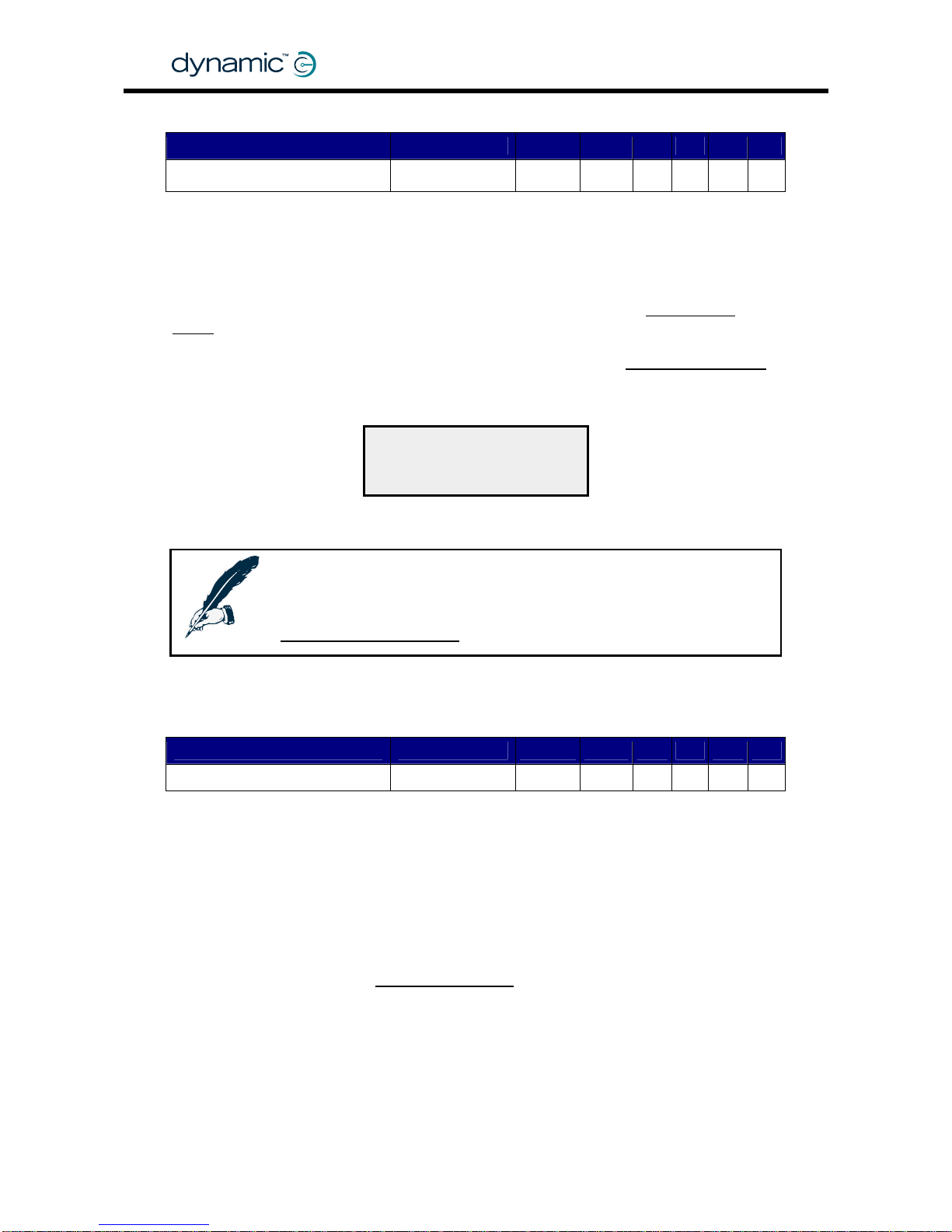
5.3.9.9 Power-up Profile Number
Parameter Possible Values Default Rev HHP Lite Std Adv
C
*
Power-up Profile Number 1 - 7 7
The Power-up Profile Number i s the Profile in which the DX System will start when the
system is switched on. If Power-up Profile Number has the value '7', the DX System will
start up with the same Drive Profile that was active when the DX System was powered
down.
Single Profile
Power-up Profile Number is also used as the profile of choice when
Mode
GBK60348
: Issue 1 – October 2007
88
(see 5.3.10.4) is enabled.
Chair Speed Enable
*The HHP can edit this parameter when Single Profile Mode and
(see
5.3.10.3) are both set to 'Yes'. The chosen 'Response' is stored in the Power-up
Profile Number parameter.
RESPONSE
1
NEXT DOWN UP
The 'Response' chosen with the HHP is
stored in Power-up Profile Number
Note:
If Single Profile Mode is enabled, make sure to only use valid user
Drive Profiles for Power-up Profile Number (1 to the value of the
Maximum Profile Number
parameter, see section 5.3.8.1).
5.3.9.10 Enable Joystick Wakeup
Parameter Possible Values Default Rev HHP Lite Std Adv
Enable Joystick Wakeup No / Yes Yes C -
Yes – The System wakes up when the joystick of the active Remote is deflected, or
when a switch or a button is pushed.
No – The System does not wake up when a joystick is deflected.
The System only wakes up when a button or a switch is pushed.
Set this parameter to 'No' to make sure that the system does not wake up when the
user accidentally deflects the joystick.
Enable Sleep Mode with the
Sleep Mode Enable parameter (see 5.3.9.8).
Page 89

MT
89
5.3.10 System Settings parameters
Parameter Possible Values Default Rev HHP Lite Std Adv
CLAM Slowdown 0 – 100 % 20 %
-,A,C
-
Neutral to PB Delay 20 – 5000 ms 100 ms
-,A,C
-
Chair Speed Enable No / Yes No
C
-
Single Profile Mode No / Yes No
C
CANH Power Switch No / Yes Yes
C
-
CAN Terminator No / Yes Yes
C
-
UCM Joystick Swap
Left/Right
No / Yes No
-,A,C
-
Rotate UCM Joystick No / Yes No
C
-
ACU Enable No / Yes Yes
-,A,C
-
ACU Joystick Swap Left/Right No / Yes No
-,A,C
-
ACU has Momentary Switch No / Yes No
C
-
ACU Momentary Switch
Timeout
No / Yes Yes
C
-
RJM Enable No / Yes Yes
-,A,C
-
RJM Joystick Swap Left/Right No / Yes No
-,A,C
-
RJM has Analog Joystick No / Yes Yes
C
-
Joystick Switch Threshold 20 – 80 % 50 % C -
5.3.10.1 CLAM Slowdown
Parameter Possible Values Default Rev HHP Lite Std Adv
CLAM Slowdown 0 – 100 % 20 %
-,A,C
-
Some actuators can place the powerchair in a physical unstable position when they
are extended (for example: seat raise actuators) . For safety, the Actuator Module
can activate a system-wide 'Slow'-state when it receives a signal from an external
switch which indicates that the chair is in an unstable position (refer to the manu al of
the Actuator Module for further details).
The 'Slow'-state reduces the maximum speed of the powerchair. Set the desired
maximum speed during this state with the CLAM Slowdown parameter. The value of
this parameter is a percentage of the Speed@Maximum parameter.
The CLAM Slowdown value is sent as an input to the global Speed Limit function.
See also section
5.3.1.2: Speed limiting options.
Page 90

5.3.10.2 Neutral to PB Delay
Parameter Possible Values Default Rev HHP Lite Std Adv
-,A,C
Neutral to PB Delay 20 – 5000 ms 100 ms -
The Neutral to Parkbrake Delay parameter sets the delay between zero speed
demand and the moment that the parkbrakes are de-energised.
The correct value of this parameter is dependent o n the mechani c s o f the parkbrake
that is used on the chair. The delay must be longer for fast acting parkbrakes.
This parameter is used to make sure that the parkbrakes do not engage
• before the powerchair has stopped at high deceleration
• before the powerchair has stopped when parking on a slope
• if the powerchair stops to change direction (for example forward to reverse)
GBK60348
: Issue 1 – October 2007
90
See also section
2.4.5: Parkbrake operation and programming.
5.3.10.3 Chair Speed Enable
Parameter Possible Values Default Rev HHP Lite Std Adv
C
Chair Speed Enable No / Yes No -
Chair Speed Enable enables the HHP to edit the
Chair Speed parameter (see 5.3.9.1)
and the active Drive Profile/Response in
Single Profile Mode (see 5.3.10.4).
Chair Speed programming with the HHP simplifies speed programming for the dealer
or therapi st. Without Chair Speed all the sp eed parameters must be adjusted for all
the Drive Profiles individually.
With Chair Speed enabled, the dealer or therapis t can ed it the Chair Speed
parameter on the HHP to adjust the global chair speed for all Drive Profiles
simultaneously. This makes it possible to quickly and easily adjust the overall chair
speed with the HHP to suit the capabilities of a specific user.
If Chair Speed is enabled, the first screen that the HHP shows when it is plugged in
is the Chair Speed screen:
The number of #s indicates the Chair Speed value.
NEXT DOWN UP
Min ########### Max
CHAIR SPEED
• Press UP or DOWN to adjust the Chair Speed value. The change will take
effect immediately, so it is possible to test the result directly while driving.
• Press NEXT to save the new Chair Speed value.
The value of 0-10 is converted to 0%-100%. After conversion the value is sent as an
input to the global Speed Pot function (see section
5.3.1.2: Speed limiting options).
It is possible to give the Chair Speed parameter an initial value with the Wizard.
Page 91

MT
5.3.10.4 Single Profile Mode
Parameter Possible Values Default Rev HHP Lite Std Adv
C
Single Profile Mode No / Yes No -
No –
Drive Profiles
91
• The DX System uses all available
(see 5.3.2).
• The Profile Select buttons on the Master Remote select the drive profile.
Yes – • Only one active Drive Profile
• The active Drive Profile is determined by the
Power-up Profile Number
parameter (see
5.3.9.9).
• The Profile Select Buttons on the Master Remote act as a digital speed po
t
• The active Drive Profile can only be changed with the HHP or the Wizard.
Enable Single Profile Mode for powerchairs that are shared between several different
users. In Single Profile Mode the users are not able to change the Drive Profile, they
can only lower the speed with the digital Speed Pot.
Only the therapist can change the Drive Profile (with the HHP or with the Wizard) to
suit a particular user on a particular day.
Notes:
1. The HHP refers to the Power-up Profile Number parameter
as 'Response'
2. If Single Profile Mode is set to 'Yes', make sure that Power-up Profile
Number does not have the value 6 or 7.
3. For the HHP to be able to change the Drive Profile in Single Profile
Mode,
Chair Speed Enable (see 5.3.10.3) must be set to 'Yes'.
5.3.10.5 CANH Power Switch
Parameter Possible Values Default Rev HHP Lite Std Adv
C
CANH Power Switch No / Yes Yes -
If set to 'No', only the DX Master Remote can switch the system off.
If set to 'Yes', any DX Module (for example the ARC switchbox) can switch the system
off via the DX BUS.
5.3.10.6 CAN Terminator
Parameter Possible Values Default Rev HHP Lite Std Adv
C
CAN Terminator No / Yes Yes -
For reliable DX BUS communication, the DX System needs two electrical CAN
terminators on the DX BUS lines. Normally the Po wer Module and the UCM Master
Remote provide this termination.
If CAN Terminator is set to 'Yes', the UCM will apply a CAN terminator to the DX BUS
CANH and CANL signal lines. This is the standard setting. Only set CAN Terminator to
'No' if there already are two other CAN terminators on the DX BUS.
Page 92

GBK60348
: Issue 1 – October 2007
92
5.3.10.7 UCM Joystick Swap Left/Right
Parameter Possible Values Default Rev HHP Lite Std Adv
UCM Joystick Swap
Left/Right
No / Yes No -,A,C -
If the Master Remote is mounted upside-down (for example with chin or tray
applications), set UCM Joystick Swap Left/Right to 'Yes'.
This parameter only applies to the Master Remote joystick, not to the Remote Joystick
Module (RJM ) or the Attendant Control Module (AC U) joysticks, or to drive switches
connected to the Master Remote. To apply Left/Right joystick swap to the RJM
joystick, use the
RJM Joystick Swap Left/Right parameter (5.3.10.14). To apply
Left/Right joystick swap to the ACU joystick, use the
ACU Joystick Swap Left/Right
parameter (
5.3.10.10).
5.3.10.8 Rotate UCM Joystick
Parameter Possible Values Default Rev HHP Lite Std Adv
Rotate UCM Joystick No / Yes No
C
-
If this parameter is set to 'Yes', the joystick operation of the Master Remote is rotated
by 90°.
Parameter
Value
Deflection Driving
direction
Forward Forward
Right Right
Reverse Reverse
No
Left Left
Forward Right
Right Reverse
Reverse Left
Yes
Left Forward
To rotate the other way around (Forward Left), set
Joystick Swap Forward / Reverse
(
5.3.8.8) and UCM Joystick Swap Left/Right (5.3.10.7) to 'Yes' as well.
Use a forward/backward symmetrical restrictor plate (for example a circular or a
square restrictor plate) if this parameter is set to 'Yes'.
5.3.10.9 ACU Enable
Parameter Possible Values Default Rev HHP Lite Std Adv
ACU Enable No / Yes Yes
-,A,C
-
If an Attendant Control Unit (ACU) is fitted, set this parameter to 'Yes' to allow the ACU
to take control over the chair.
If no ACU is fitted, setting this parameter to 'Yes' will slightly decrease the performance
of the chair, because the DX System will r egu larly search for the presence of an ACU.
Page 93

MT
5.3.10.10 ACU Joystick Swap Left/Right
Parameter Possible Values Default Rev HHP Lite Std Adv
-,A,C
ACU Joystick Swap Left/Right No / Yes No -
Set ACU Joystick Swap Left/Right to 'Yes' if the Attendant Control Unit is mounted
• upside-down
• vertically to give forward driving when the joystick is deflected down.
This parameter only applies to the ACU. To apply Left/Right joystick swap to the RJM
joystick, use the
RJM Joystick Swap Left/Right
93
parameter (5.3.10.14). To apply
Left/Right joystick swap to the Master Remote joystick, use the
UCM Joystick Swap
Left/Right
parameter (5.3.10.7).
5.3.10.11 ACU has Momentary Switch
Parameter Possible Values Default Rev HHP Lite Std Adv
C
ACU has Momentary Switch No / Yes No -
The ACU has a switch to tell the Master Remote that it wants to take control of the
powerchair. This switch can be
• a latching switch (a switch that stays in the same position after switching), or
• a momentary switch (a switch that returns to its original position, for example a
push button).
If the ACU has a momentary switch, set ACU has Momentary Switch to 'Yes'.
Note:
The DX-ACU1 is fitted with a latching switch.
5.3.10.12 ACU Momentary Switch Timeout
Parameter Possible Values Default Rev HHP Lite Std Adv
ACU Momentary Switch
Timeout
No / Yes Yes C -
Yes – When the attendant has not operated the ACU for two minutes, the
DX System automatically switches from Attendant M ode to Use r Mode. Th is
allows the user to resume driving.
No – The DX System remains in the Attendant Mode until the Momentary Switch is
pushed to release the control of the powerchair back to the user.
If ACU has Momentary Switch (
5.3.10.11) is set to 'No', the value of ACU Momentary
Switch Timeout is ignored. Therefore, this parameter has no effect on the DX-ACU1.
Page 94

GBK60348
: Issue 1 – October 2007
94
5.3.10.13 RJM Enable
Parameter Possible Values Default Rev HHP Lite Std Adv
RJM Enable No / Yes Yes
-,A,C
-
If a Remote Joystick Module (RJM) Secondary Remote is fitted, set RJM Enable to 'Yes'
to allow the RJM to operate when the Drive Profile has the RJM selected as the
Joystick Source (5.3.8.7).
If the RJM is not connected, a Module Fault (flash code 1) will occur when a Drive
Profile is selected that has the RJM as the Joystick Source.
See section
6.2: Secondary Remotes.
5.3.10.14 RJM Joystick Swap Left/Right
Parameter Possible Values Default Rev HHP Lite Std Adv
RJM Joystick Swap Left/Right No / Yes No
-,A,C
-
If the Remote Joystick Module (RJM) is mounted upside-down (for example with chin
or tray applications), set RJM Joystick Swap Left/Right to 'Yes'.
This parameter only applies to the RJM. To apply Left/Right joystick swap to the ACU
joystick, use the
ACU Joystick Swap Left/Right parameter (5.3.10.10). To apply
Left/Right joystick swap to the Master Remote joystick, use the
UCM Joystick Swap
Left/Right
parameter (5.3.10.7).
5.3.10.15 RJM has Analog Joystick
Parameter Possible Values Default Rev HHP Lite Std Adv
RJM has Analog Joystick No / Yes Yes
C
-
The RJM joysticks come in two different versions:
• Proportional control. These joysticks give a gradual 0-100% range.
For example: the mini joystick or the finger steering control.
• Switched control. These joysticks only give an on/off signal for each direction.
For example: the Heavy Duty joystick or the Sip and Puff Module.
If the DX System uses a switched joys tick, set RJM has Analog Joystick to 'No'. If this
parameter has the value 'No', the UCM ignores small speed signals and small
direction signals from this joystick.
Page 95

MT
Unwanted small direction signals can be caused by a small analog offset signal when
a switched joystick outputs "zero". These small direction signals can cause the
powerchair to veer slightly.
Intended
direction
Actual
direction
Veer
Small direction signals can cause a slight veer
With a proportional joystick the user can correct for any veer by mo ving the joystick
slightly sideways. A switched joystick does not have this capability.
If RJM has Analog Joystick has the value 'No', the UCM ignores the small speed and
direction signals generated by the joystick processing. This makes sure that the
powerchair does not veer.
The size of the "zero"-area is determined by the value of the
Neutral Maximum
parameter (see
5.3.9.3)
zero F-R
zero F-R
zero L-R
zero L-R
Neutral
Maximum
10%
zero
zero
F-R
zero
L-R
Neutral
Maximum
30%
zero
Neutral
Maximum
10%
RJM has Analog Joystick: Yes RJM has Analog Joystick: No
zero
L-R
zero
F-R
Note:
1. Setting RJM has Analog Joystick to 'No' can also help users who
have problems to steer straight ahead.
2. Veer can also occur if the performance of the two drive motors is
not equal. See section
95
4.3.2.5: Veer Compensation
Page 96
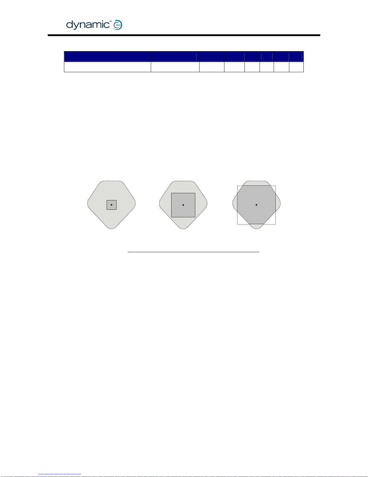
5.3.10.16 Joystick Switch Threshold
Parameter Possible Values Default Rev HHP Lite Std Adv
Joystick Switch Threshold 20 – 80 % 50 % C -
Some functions such as actuator operation and lighting control can use the joys tick
as an input switch. Joystick Switch Threshold sets the value beyond which the
DX System assigns the joystick to be in the "on" position.
Set this parameter lower than 50% to
• allow a forward-sideways or a reverse-sideways switch operation when the
restrictor plate does not physically allow this
• allow users with very little hand movement to operate the joystick switches
comfortably.
Joystick Switch
Threshold 20%
Joystick Switch
Threshold 80%
GBK60348
: Issue 1 – October 2007
96
See also section
5.3.4: Reducing the movement to operate the joystick.
off
on
Joystick Switch
Threshold 50%
on
off
on
off
Page 97

MT
6 DX Modules
6.1 Introduction
Including the Power Module and the Master Remote, a DX System can contain up to
16 DX compatible modules dependent on the application.
Available types of DX Modules are
• Remote Joystick Module (RJM),
o DX-RJM Secondary Remotes
o Switch modules
• Attendant Control Unit (ACU), joystick with attendant switch and Speed Pot
o DX-ACU1
• Actuator Remote Control (ARC), 5 channels of extend/retract switches
o DX-ARC / DX-ARC-SWB
• Servo Steering Motor Modules
o DX-SLM, for steering servo motor control + lights
• Lighting Modules
o DX-SLM/ DX-LM/ DX-CLAM
• Actuator Modules
o DX-CLAM/ DX-TAM
• Environmental Control Unit Modules (ECU)
• DX-KEY Modules enable third party devices to inter face with t h e D X System
The DX System has the option to declare some DX Modules as safety critical. This
makes sure that the DX System will not operate when that particular module is not
detected during power-up.
Warning:
Each DX Module has its own Installation Manual that describes the
installation requirements of that particular module. This chapter gives a
brief description of several DX Auxiliary Modules, but it is not a substitute
for the manual of those modules. If you have purchased a specific
DX Module, read and understand the manual of that module before
using the module.
6.1.1 The GPSB/SLIO
Some DX Modules, such as the DX-RJM Secondary Remote joystick, do not perform
any processing or storing of parameter values themselves. All the processing for these
modules is done in the UCM (see
5.1.1). The modules only read the joystick position
and send this throu gh the DX BUS to the UCM.
Because they don't need any local intelligence, these modules have a simple
communication device that connects them to the DX BUS. This communication
device is internally located on the 'General Purpose SLIO Board' (GPSB) and is called
a 'Serial Linked I/O' (SLIO) device.
97
Page 98

6.2 Secondary Remotes
A Secondary Remote is a secondary user input device, for example an attendant
joystick. A Secondary Remote
• converts user input (the joysti ck or the switches, dependent on the type of
Secondary Remote) to speed and direction signals, and
• sends the speed and direction signals as DX BUS messages to the Master
Remote via the DX BUS.
To use a Secondary Remote, select it as the
Joystick Source
GBK60348
: Issue 1 – October 2007
98
(see 5.3.8.7) in one of the
Drive Profiles (see
5.3.2).
6.2.1 Available Secondary Remotes
Secondary Remote Applications
Attendant joystick
Attendant can take drive control with Attendant/User switch
Attendant can adjust chair speed
DX-ACU1
Dual Control
Attendant joystick
User joy stick for Master Remotes without joystick
User joystick mountable on the armrest or away from it
DX-RJM
Compact chin remote
Remote Joystick
Module
Users wi thout finer hand mo vement
Situations where a normal joystick can be damaged
DX-RJM-HD
Heavy Duty Joystick
Full proportional control with very little movement or force
Completely sealed - can be used as a tongue joystick
DX-RJM-MINI
DX Mini Joystick
Zero force optical operation
Users with very little strength in their hand/fingers
DX-RJM-VIC-CCD
Finger Steering
Control
Full proportional control
Finger movement of 2 mm per direction is enough
Driven by four momentary switches,
Either separate switches or
Switches combined in one unit (for example the wafer switch)
DX-ACC4
Provides up to eight driving directions
Four Switch Interface
Page 99

MT
99
6.3 DX Steering/Actuator/Lighting Modules
DX Module Function / Applications
DX-SLM / DX-SLM-TUV
Servo Lighting Module
Drives a separate motor for steering castor wheels
Commonly used for high speed outdoor powerchairs
24V, 30A peak, 5A continuous Servo steering
24V lighting (DX-SLM) or 12V regulated lighting (DX-SLM-TUV)
DX-CLAMB
Combined Lighting
and Actuator Module
Compact module to connect all common functions:
• Five actuators
• Front lights, Rear lights
• Left and right turning indicators, Hazard lights
All power and control signals provided through the DX BUS
Soft Start feature provides smooth actuator control
Slow/Stop input (for actuator position switches)
DX-LM-Z / DX-LM-TUV
Lighting Module
24V lighting (DX-LM-Z)
12V regulated outputs for TÜV approved lighting (DX-LM-TUV)
• Front lights, Rear lights
• Left and right turning indicators, Hazard lights
Short-circuit and open-circuit detection
DX-TAM
Two Actuator Module
Simple and compact solution for two actuator control
All power and control signals provided through the DX BUS
Soft Start feature provides smooth actuator control
Slow/Stop input (for actuator position switches)
Programmable current limits and maximum operation time
DX-ARC5
Actuator Remote
Control
Separate handset for actuator control
Ideal for
• attendant use
• users who can not use the controls of the Master Remote
Controls up to 5 s e a t p o s i ti oning actua to r s
Actuators can optionally be operated while driving
Can be programmed to control horn, lights and driving
Needs DX-CLAMB or DX-TAM to operate
DX-ARC-SWB
ARC Switchbox
Controls up to 5 s e a t p o s i ti oning actua to r s
Can be programmed to control horn, lights and driving
Operates with external switches ( DB15 connector)
Choose switch combinations and mounting positions freely
One extra 24V/1A power supply output
Secondary Remote Applications
Five switch inputs plus extra 'Emergency Stop' input
Accepts input devices terminated in a '9-pin D' connector
Analog Latch mode gives infinitely adjustable cruise speed
DX-5SW
3 momentary modes, 4 latched modes
5 Switch Module
Recognises soft and hard sips and puffs
Sip and puff pressures programmable
Analog Latch mode gives infinitely adjustable cruise speed
DX-SNP
3 momentary modes, 4 latched modes
Sip and Puff Module
Page 100

6.4 DX Environmental Control Modules
GBK60348
: Issue 1 – October 2007
100
DX Module Function / Applications
Needs the DX-SCR, the G90 or the G91 Remotes to operate
Uses the Secondary driving Remote as input control
'8 Output mode' controls up to eight separate devices
DX-ECU
'Mouse mode' acts as a mouse mover, fifth switch acts as click
Environmental
Control Unit
Up to two DX-ECU modules in one DX System
All outputs are isolated relay co ntacts
Learning infra-red remote control
360° transmission
Supports GEWA devices
DX-IRIS2
Works together with the Specialty Controls Master Remote
Infra-Red Transmitter
Receives mouse move commands from the DX-IRIS2
Works alongside the computer's existing mou se
Serial port connection
DX-PCMR
USB-Serial converter: DX-USB-COM
Infra-Red Mouse
Receiver
6.5 DX Auxiliary Modules
DX Module Function / Applications
Powerchair lock
Makes sure that only authorised people can drive the chair
Lighting and actuator functions are still operational wh en the
powerchair is locked
DX-ACC2
Drive Stop Module
Small charger socket to mount in a convenient place
Use with remotes that do not have a charger socket
Use as an alternative to the Master Remote charger socket
DX-ACC3
Maximum 8 A charging current
Charger Socket
Module
 Loading...