

Page 1
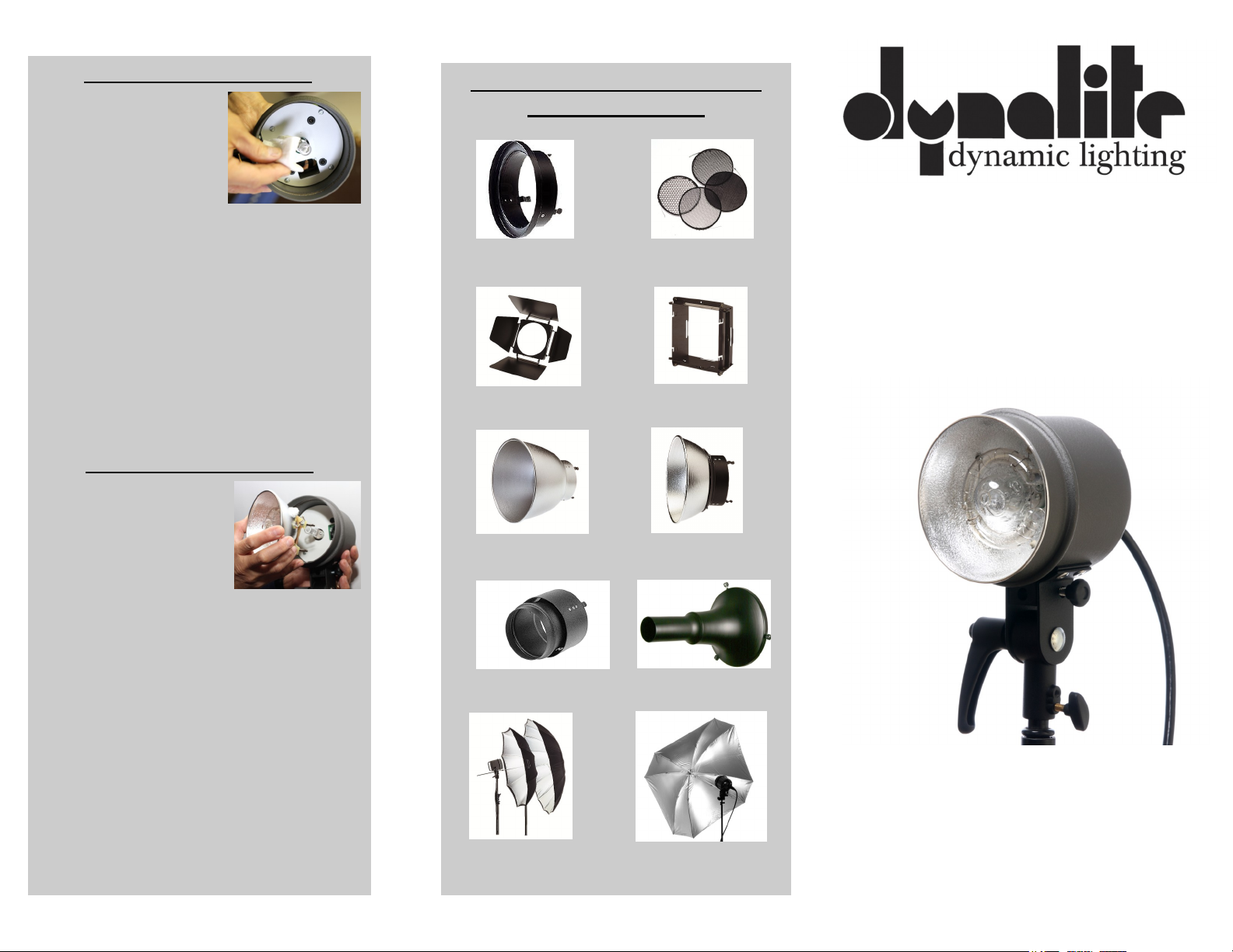
Replacement of Modeling Lamp
1. Unplug the flash head
from the power pack
and allow the flash
head to cool before
touching the modeling
lamp.
2. Remove flash head
accessories if present.
3. Remove the flash tube from the head in order to reach the modeling lamp.
4. Remove the modeling lamp by carefully
griping it with a soft cloth and pulling
straight out.
5. Install the new lamp by aligning the pins
with the socket and press the lamp in place.
Please note: Do not touch the new lamp with your hands.
Oils from your hands can cause premature failure of the
lamp or could cause an unexpected shattering of the lamp.
Replacement of the Flash Tube
1. Unplug the flash head
from the power pack
and allow the flash head
to cool before touching
the flash tube.
2. Remove flash head accessories if present.
3. Remove the flash tube by rocking and or
pulling the outer edge of the reflector assembly out of the flash housing.
4. Install the new flash tube assembly by aligning the three connection pins with the three
connection sockets inside the flash housing.
Ensure that the connection pins are aligned
correctly and in the proper configuration
before installing the flash tube assembly.
Gentle push the reflector/flash tube assembly until the edge of the reflector is flush
with the outer edge of the flash housing.
Note: Use only the appropriate flash tube.
Dynalite Lighting Controls and
System Accessories
RR-GH
RR-AFBD RR-AF
RR-50 RR-80
RR-AR
UCBW-36
UBBW-44
RR-4G
SR-65SN
UQSS-48
Instruction Manual
For Model MH2065v
Fan Cooled Strobe Head
DYNALITE INC
1050 Commerce Ave ● Union ● NJ ● 07083
908-687-8800 Phone ● 908-686-6682 Fax
www.dynalite.com
R-11/20/2013
Page 2
DYNALITE MH2065v INSTRUCTIONS
Important Safeguards
When using this flash equipment, include the fol-
lowing safety precautions.
· Read and understand ALL instructions and
specifications before using your Dynalite
equipment.
· Care must be taken when handling the flash
heads as injury could occur from touching the
modeling lamp(s) or flash tube(s).
· Do not operate a power pack or flash head
with a damaged cord or if the unit has been
dropped and is visually damaged.
· If an extension power cord is necessary, a
suitable current rating should be used. Cords
rated for less than 15 amps may overheat.
· Care should be taken to arrange the cord so
that it will not be tripped over or pulled from
the electric source outlet.
· Unplug the power pack from the electrical
outlet when not in use. NEVER yank the cord
to pull the plug from the electrical outlet.
· Let flash heads cool completely before putting
them away. Loop flash cables in an 8” to 10”
diameter coil when storing.
· DO NOT allow power cord(s) or flash head
cable(s) to hang on or touch hot surfaces.
· To avoid electrical shock hazard, power cord
(s) or flash head cable(s) must be properly
grounded. DO NOT attempt to disassemble
the power pack. Incorrect reassembly could
cause an electrical shock hazard when a power
pack is subsequently used. Take it to a qualified Dynalite Service technician when service
is required.
· When the power pack is not in use for one
month or more, it is wise to periodical plug
the power pack in and turn it ON for a couple
of hours. It is not necessary to operate a flash
head during this “idling” time.
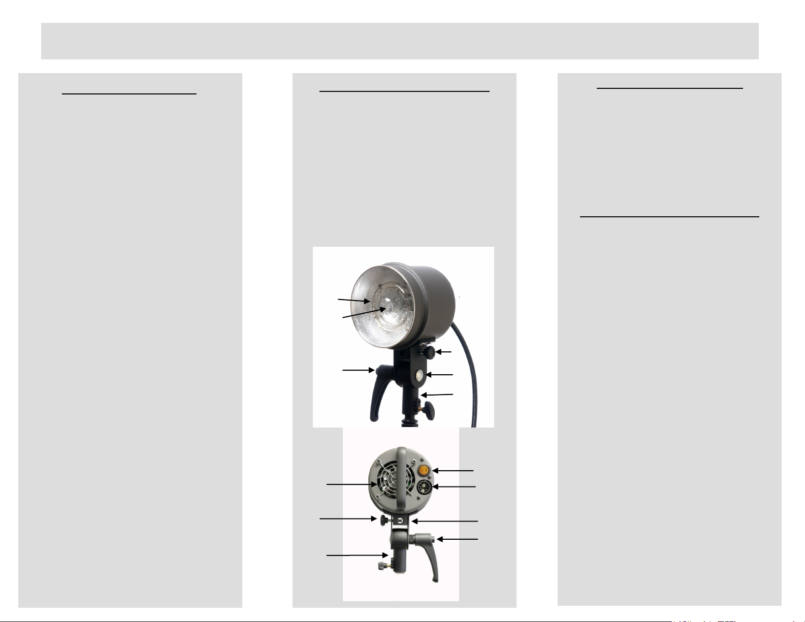
MH2065v Parts Description
Flash Tube (2000 W/s part # 2406)
Modeling Lamp (300 Watt part # 0521 or
optional 650 Watt, part #0520)
Tilt Head
Light Stand Swivel Block (part #P60101)
Locking Tilt Head Handle,
(Multi-position Ratcheting, (part# C47098)
Umbrella Locking Knob (part# C47103)
‡ Illuminated Model Lamp Switch
ˆ Flash Cable Socket
‰Cooling Fan
Š Umbrella Mounting Hole 9mm.
Standard Flash Head Features
· UV Color Corrected Flash Tube (2000 w/s
part number 2406
· Model Lamp 300 W, Part Number 0521
· Optional Model Lamp 650 W, Part Number
0520
· Universal Light stand Mounting (5/8”)
· Umbrella Mount (9mm hole)
· Protective Flash Head Cover
Setting Up The MH2065v Flash Head
1. Unpack your new Dynalite Flash Head and
make sure that all the items are accounted
for and in accordance with the parts description list.
2. Before firing the flash head, be certain to
remove the plastic flash head protective
cover (Yellow Cap).
3. Mount the flash head to an appropriately
sized (5/8”) and secure the flash head to the
light stand using the locking knob (see
Parts Designation).
4. With the power pack OFF, connect the
power pack cable to the head cable socket
on the flash head. With the power pack
OFF, connect the other end of the power
pack cord to the power pack socket. Ensure
that both connectors are securely fastened
before turning the power pack ON.
Note: When using the optional 650W Modeling lamps in the MH2065v flash heads use no
more than two (2) flash heads in a power
pack at one time, and only one per side
(bank)
 Loading...