

Page 1
Colour Touch Screen Installation Manual
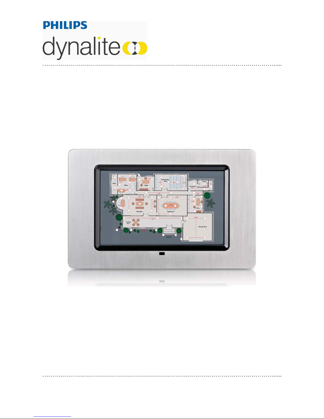
DTP170
C
Warning…………………………………………….. 2 Internal View……………………………………….. 3
Features…………………………………………….. 2
Important Safeguards…………………………….. 2 Connecting Serial Control Cables……………….. 5
Specifications………………………………………. 3
WMGD Pty Limited trading as Philips Dynalite
Unit 6, 691 Gardeners Road Masc ot NSW 2020 Australia
+61 8338 9899 y f +61 2 8338 9333 y inf o@dynalite-online.com y ABN 33 097 246 921 y dynalite-online.com
t
contents
Mounting…………………………………….……… 4
Page 2
Warning
x TO REDUCE THE RISK OF FIRE OR
ELECTRIC SHOCK, DO NOT EXPOSE
THIS DEVICE TO RAIN OR MOISTURE.
x DO NOT ENERGISE UNLESS THE
FRONT COVER IS IN PLACE.
x INSTALLATION, PROGRAMMING AND
MAINTENANCE MUST BE CARRIED OUT
BY QUALIFIED PERSONNEL
features
x Fully configurable control panel
x DTP170 fascia accommodates
practically any flat architectural
surface medium.
x Sophisticated feature rich LCD
Colour Touchscreen panel.
x Controls 255 areas, 255 channels
per area, 96 scenes per area,
250 events, 8 tasks.
important safeguards
Read the Instructions – We
recommend that you read this
Instruction Manual prior to
commencement of installation.
Special Programming – This device
will only operate in basic modes until
programmed. If programming is
required, contact your local agent for
details. Once the data cable is
connected to the device, the factory
default settings will allow the panel to
control all channels in all dimmers.
Mounting Location – This device must be
mounted indoors away from direct sunlight.
The optimum viewing angle is 90
˚
. Ensure
that the LCD display will be at, or slightly
below, eye level for all users. Take this
into account when deciding the mounting
location.
Data Cable – The recommended cable for
connections to the serial port is screened,
stranded RS485 data cable with three
twisted pairs. Part numbers for various
manufacturers are listed on page 5. This
cable should be segregated from mains
cables by a minimum distance of 300mm.
If anticipated cable runs are over 600
metres for serial cables or 12 metres for
analogue cables, consult your Dynalite
dealer for advice. Do not cut or terminate
live data cables.
The Display – The DTP170’s LCD display
and touch membrane are very sensitive to
damage from sharp or hard objects. Never
operate the panel using anything other
than your fingertip. Ensure there are no
protrusions when fitting the panel to the
wall. If cleaning is required, use a dry cloth
or soft cloth with alcohol, neutral detergent
or ethanol for clearing of dirt and
smudging.
Power Supply – The DTP170 Touch
Screen requires a DC supply. Due to the
extra load of the backlighting, supply from
the DyNet network may not be of an
adequate capacity. We recommend the
installation of an additional 12V - 15V DC
power supply rated at 1A minimum,
connected directly to the +12V and GND
terminals on the panel (in parallel to the
network +12V and GND cables). This may
require additional wiring. When selecting
the power supply location, keep in mind
that a power supply hidden locally in the
wall or ceiling is difficult to service.
2 DTP170 Installation Manual Rev C.docx
Page 3

Specification
Supply +VE: 12V DC @ 0.6A from the DyNet Network
IO ports: 1 x RS485 DyNet serial port, 1 x RJ45 10/100BaseT Ethernet port,
1 x USB Type Mini-B socket, 1 x USB Type A socket
Screen: Viewable Area: 178mm (7”) diagonal, (H 9.79cm x W 13.05cm)
Resolution: 800x480 (WVGA / 16:9 ratio)
Colour Depth:
Contrast: 300:1 Luminance: 280 cd/m2
Screen Type: TFT LCD
Viewing Angle: H 65º Vtop 50º Vbottom 60º
Backlight: Dimmable LED 40000 hr rated
Touch Overlay: 4 Wire Resistive
Operating System and
Software:
CPU: Intel XScale PXA310 624MHz, 128MB SDRAM, 512MB FLASH
Compliance: CE, C-Tick
Ambient Temperature: 0º to 40ºC ambient temperature. 10% to 90% RH non condensing
Audio: Power Output: 0.5W RMS x 2
Construction: Concealed fixings facia, metal body & wallbox
Windows CE 6.0, Internet Explorer 6, Windows Media Player 9 /
MP3 support
Speakers: 2 with 25mm diameter cones
Line Out via 3.5mm stereo jack
65,536 (16bit)
Dimensions:
Exposed Face:
Hidden Wallbox:
Packed Weight: 1.9kg
H 149mm x W 233mm x D 7mm
H 136mm x W 220mm x D 70mm
internal view
3
Page 4

dimensions
DTP170 with Wallbox Fitted
DTP170 without Wallbox
installation
Selecting an Installation Location
Remember the display height should be equal to, or slightly below, the eye level of all users. Avoid
a location in which bright light is present, either directly in front of, or behind, users.
Installing the Product
The DTP170 Touch Screen is designed to be flush-mounted, with or without a wallbox. If using a
wallbox, separate the wallbox from the Touch Screen and make sure no dust or debris enters the
Touch Screen during installation. Knock out a cable entry point on the wallbox, then prepare a
hole:
140mm high x 218mm wide x 71mm deep.
The wallbox can then be fixed in place using an appropriate method.
Power Supply
This product consumes up to 600mA from the DyNet network. Ensure that appropriate DyNet DC
supply is available to operate this product and any other DC supply consuming peripherals that
may be present on the bus.
4 DTP170 Inst allation Manual Rev C.docx
Page 5

Connect Data Cable in a ‘Daisy Chain’
RJ12 Socket Connections
Serial Cable Permanent Connections
connecting serial cables
Serial Cable Connections
There is one RS485 port for DyNet
the form of a RJ12 socket, on the front, which is
used for the temporary connection of a PC or a
Portable Programmer (DPP601). There are data
terminals on the rear, for permanent connections.
The recommended cable for connections to the
serial port is screened, stranded RS485 data
cable with three twisted pairs. Recommended
cable types include:
Belden: 9503
Dynalite: DYNET-STP-CABLE
Garland: MCP3S
Hartland: HCK603
M&M Cable: B2003CS
M&M cable: B9503CS
Multicables: AWM E120236 2092 20
RS Components: 368-687
One pair is paralleled for GND, one pair
paralleled for +12V, and one pair used for DATA
and DATA.
Recommended Cable Colour Coding
Green/White pair: paralleled for GND
Orange/White pair: paralleled for +VE
Blue/White pair: Blue for DATA +
White for DATA -
The colour-coding scheme used is not critical, as
long as the same scheme is used throughout the
installation. The shield should be terminated in
the “SHIELD” terminal if present, otherwise it
should be terminated to the metal chassis of
electrically earthed devices, and looped through
on devices that are not electrically earthed.
Serial Cable Connecting Method
The recommended connecting method is to
‘daisy chain’ devices (starting at the first device,
then looping in then out of devices, with a single
cable terminating at the last device. There
should not be any spurs or stubs, and only the
first and last device should terminate one cable.
All other devices should terminate two cables).
Devices may be wired in any order. The Data
Cable should be. A data cable that is
®
signals, in
DTP170 Install ation Manual Rev C.docx 5
Page 6

Dynalite Manufactured by WMGD Pty Ltd (ABN 33 097 246 921). All rights reserved. Dynalite, Dimtek, DyNet and DLight and associated logos are the registered
DTP170 I nstall ation Manual Rev I.doc Specifi cations and des ign subject to change without notice.
trademarks of Dynalite Intelligent Light Pt y Ltd. Not to be reproduced without permission.
Unit 6, 691 Gardeners Ro ad Mascot NSW 2020 Aust ralia Tel: +61 2 8338 98 99 Fax: +61 2 8338 9333
DTP170 Installation Manual Rev C .docx 6
E-mail: dynalite.info@philips.com
Web: Philips.com/d ynalite
 Loading...