

Page 1
DDRC420FR
4 x 20A Relay Controller
Instruction Manual
features
4 x Feed Thru Outputs – Latching Relays rated at 20A inductive, no
de-rating necessary
Separate Control Supply – 1 phase at 0.1A
Manual Overrides for each channel
Powerful Internal PLC – Custom scripts can be written to provide
process control based on conditional logic.
Many Control Options – Control of this device can be via a
combination of methods eg. Serial control port, relay contacts, push
button control panels, infrared receivers and timeclocks.
Simple Installation – DIN Rail mount facilitates installation.
All connection terminals accessible without disassembly.
Warning – this device is a class A product. In a domestic environment this
product may cause radio interference, in which case the user may be required
to take adequate measures.
Manual Override Switches – These switches do not provide permanent
isolation. Isolate at the supply before performing work on load circuits.
Special Programming – Once powered and terminated correctly this device
will only operate in basic mode. A new Dynalite panel will turn on all lighting
channels from button 1 and turn off from button 4 if network terminations are
correct. Only once the full network is test correct can commissioning begin.
Advanced functions can be commissioned via Envision software. If
commissioning is required, contact your local distributor for details.
Check Connections – Tighten all load-carrying screw connections, as
vibrations from transport can cause terminal block screws to become loose.
Power Sources – This device should only be operated from the type of supply
specified on the front cover. This device must be earthed.
Output Circuits – The load circuit should not exceed the specified capacity of
20A. Loads should be calculated to ensure that the overall maximum capacity
of 80A is not exceeded. Each channel shall be protected with a HRC fuse or
MCB rated 20A or less. Output circuits are suitable for Single Phase or Three
Phase Star (with Neutral) only, Delta wiring is not supported.
Mounting Location – Install in a dry, well-ventilated location. Controllers may
emit some mechanical noise. Take this into account when deciding the
mounting location.
Data Cable – Use screened, stranded RS485 data cable with three twisted
pairs. Segregate from mains cable by 300mm minimum. Connect devices in a
‘daisy chain’. A data cable connected to an energized device is live. Do not
cut or terminate live data cables.
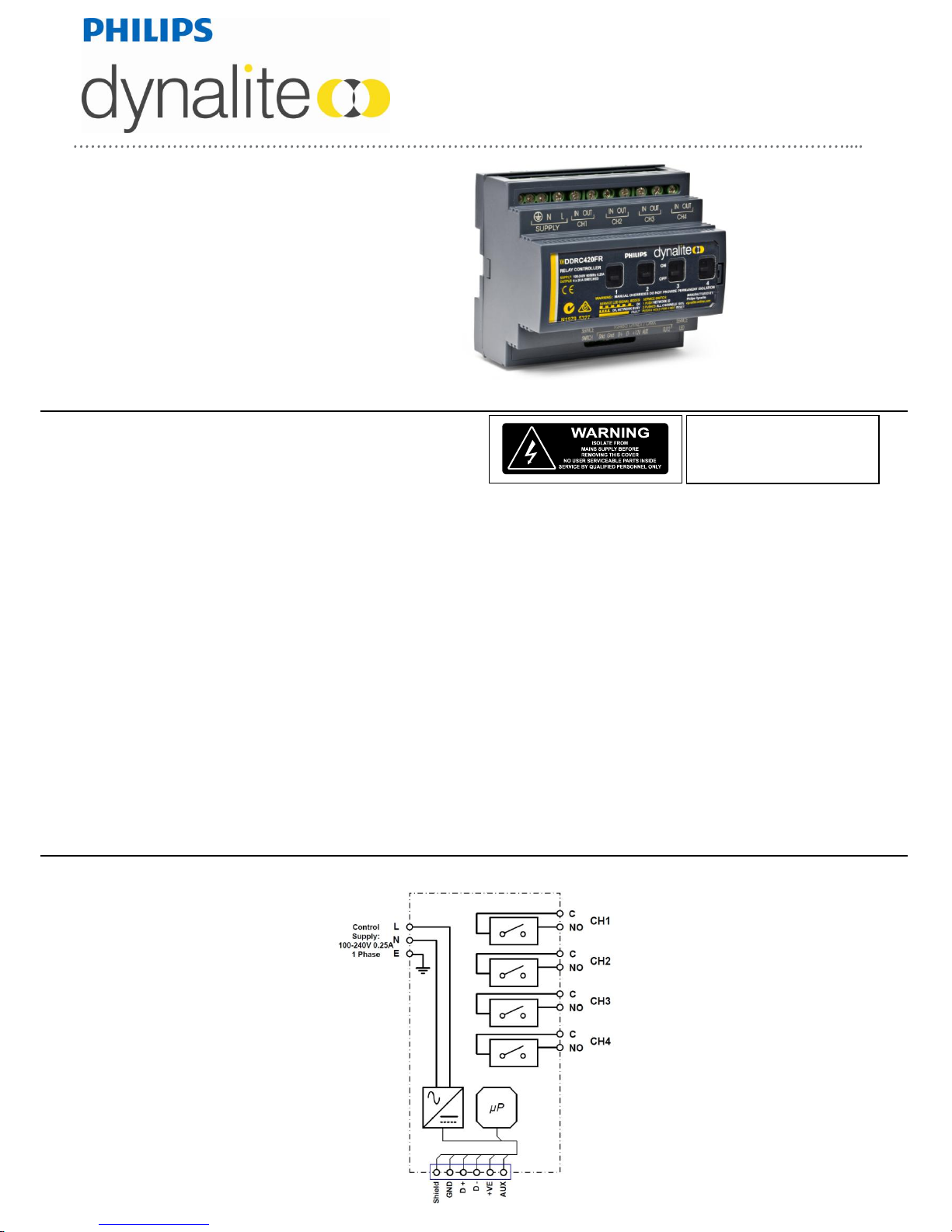
electrical diagram
To reduce the risk of fire or electric shock, do
not expose this device to rain or moisture. Do
not energise unless the front cover is in place.
The device must be earthed. Installation,
programming and maintenance must be carried
out by qualified personnel.
Page 2
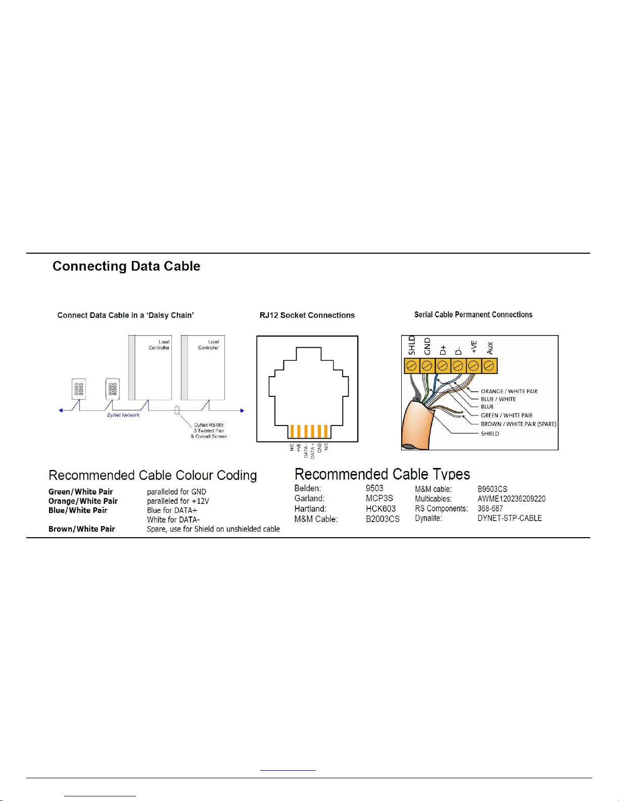
connecting data cable
installation steps
1. Mount the device on a DIN rail inside an approved enclosure.
2. Calculate loads to ensure any channels are not overloaded, then connect loads to the output channels. The maximum loading of this device is as
follows:
Maximum Channel Load: 20A 230V AC
Total Box Load: 80A
Connect supply and load cables to each channel. Note that this device must have an individual supply circuit for each channel. The supply circuits
can be on any phase. Note that loads must have a Neutral (1 Phase or 3 Phase Star), Delta wiring is not supported.
3. Connect a single phase 0.1A feed to the supply terminals. This device must be earthed.
4. Connect data cables to the device as per the diagrams below.
5. If the Auxiliary input is to be used, connect a dry contact device in between the AUX and GND terminals. Keep cable runs between the AUX
terminals and the dry contacts under two metres. The function of the Auxiliary input will need to be programmed at the time of commissioning.
product specifications
product specifications
Supply:
100-240V 50/60Hz Single Phase at 0.25A
Load Outputs:
4 x Feed Thru Outputs at 20A per channel, maximum device load of 80A
Wiring topology: 1 Phase & Neutral and 3 Phase & Neutral Star. Delta not supported
Switching Device:
Relay – 50A 230V AC inductive (5000W Lighting Load rated)
Supply Terminals:
1 x Phase, 1 x Neutral, 1 x Earth, up to 1 x 4mm2 cable per terminal
Load Terminals:
IN, OUT for each channel, up to 1 x 4mm2 cable per terminal
IO:
1 x RS485 DyNet/DMX512 Serial port
1 x AUX programmable dry contact input
DyNet DC Supply:
120mA (Supply for approx 6 panels)
Preset Scenes:
170
Compliance:
CE, C-Tick
Operating Environment:
0° to 50°C ambient temperature
0% to 90% RH non-condensing
Construction:
Polycarbonate plastic DIN rail mount
Dimensions:
H 93mm x W 105mm x D 75mm
Weight:
0.8kg
DDRC420FR Instruction Manual Rev G.doc. Specifications subject to change without notice.
Dynalite manufactured by WMGD Pty Limited (ABN 33 097 246 921). Unit 6, 691 Gardeners Road Mascot NSW 2020 Australia Tel: +61 2 8338 9899 Fax: + 61 2 8338 9333
E-mail: dynalite.info@philips.com Web: philips.com/dynalite
 Loading...