

Page 1
DBC410
4 x 10A HF Ballast Controller
Installation Manual
contents
Warning……………………………………………..
2
Hardware Controls.……………………………………..7
Features…………………………………………….. 2
Troubleshooting………………………………………… 8
Important Safeguards……………………………..
2
Specication..……………………………………………
8
Internal View……………………………………….. 3
Mounting…………………………………….………
4
Supply & Load Cable Connections.……………… 5
Connecting Serial Control Cables……………….. 6
Supplied by:
Page 2
2 DBC410 Installation Manual Rev K.docx
features
Single Phase Supply
Simple supply requirement, 40A single
phase.
4 Switched Outputs
Each 10A output is switched via a high
specification relay with specially treated
contacts which prevent contact fusion when
switching very reactive loads.
4 Control Outputs
Each of the 4 optically isolated outputs can
be configured to be either 1-10V, or DSI
Serial control, covering the latest types of
HF Fluorescent Ballasts. Also compatible
with 1-10V and DSI dimmable electronic
transformers.
MCB Protection
Each mains output is protected by a single
pole magnetic circuit breaker.
Many Control Options
Control of this device can be from a
combination of methods, eg. serial control
port, relay contacts, push button wall
stations, infra red receivers and timeclocks.
Easy high-level interface to other popular AV
control systems and Building Management
Systems (BMS) is also available.
Simple Installation
Wall-mount enclosure with mounting lugs
facilitates installation. Cable knockouts are
provided, at the top of the enclosure for
supply and load cables, with low voltage
(LV) control at the bottom.
important safeguards
Warning – this is a class A product. In a domestic
environment this product may cause radio interference, in
which case the user may be required to take adequate
measures.
Read Instructions – We recommend that you read this
Instruction Manual Prior to commencement of installation.
Retain instructions and give the end user.
Troubleshooting - If problems are encountered, check
the Troubleshooting section on page 8.
Special Programming – Once powered and terminated
correctly this device will only operate in basic mode. A
new Dynalite panel will turn on all lighting channels from
button 1 and turn off from button 4 if network terminations
are correct. Only once the full network is test correct can
commissioning begin. Advanced functions can be
commissioned via Envision software. If commissioning is
required, contact your local distributor for details.
Check Connections – Treat this device as a
switchboard that has been shipped. Tighten all loadcarrying screw connections, as vibrations from transport
can cause MCB and terminal block screws to become
loose.
Power Sources – This device should only be operated
from the type of supply specified on the front panel. This
device must be earthed.
Output Circuits – The load on a circuit should not
exceed the specified capacity of 10A. Loads should be
calculated to ensure that the overall maximum capacity of
40A is not exceeded.
Load Control Circuits – If this device is being used to
control 1-10V or DSI HF Fluorescent Ballasts, a 2 core
mains rated control cable is required to be run to the
loads, in addition to the mains feed.
Load Type – Default settings are for load control outputs
to be 1-10V. Check to see what type of HF Fluorescent
Ballasts are in the luminaries. Do not terminate the
control lines to any DSI loads until the relevant channel
has been programmed as DSI. When connecting 1-10V
load control lines, pay attention that the correct polarity is
maintained.
Megger Testing – Do not megger test any circuitry
connected to the dimming system, as damage to the
electronics may result.
Mounting Location – This device must be mounted right
way up, on a vertical surface (refer to page 4 for
mounting instructions). The specified minimum clearance
of 100mm for all sides must be adhered to. Install in a
dry, well-ventilated location. Controllers may emit some
mechanical noise. Take this into account when deciding
the mounting location.
Data Cable – The recommended cable for connections to
the serial port is screened, stranded RS485 data cable
with three twisted pairs. Part numbers for various
manufacturers are listed on page 6. This cable should be
segregated from mains cables by a minimum distance of
300mm. If anticipated cable runs are over 600 metres for
serial cables, consult your dealer for advice. Do not cut or
terminate live data cables.
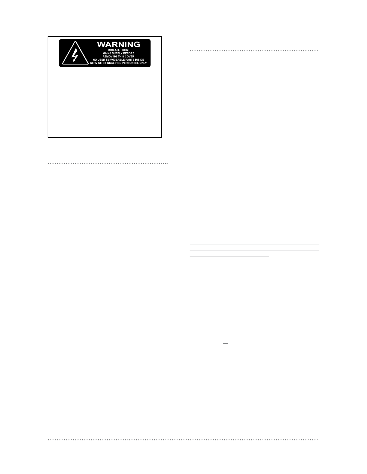
Warning
TO REDUCE THE RISK OF FIRE OR
ELECTRIC SHOCK, DO NOT EXPOSE THIS
DEVICE TO RAIN OR MOISTURE.
DO NOT ENERGISE UNLESS THE FRONT
COVER IS IN PLACE.
THIS DEVICE MUST BE EARTHED.
INSTALLATION, PROGRAMMING AND
MAINTENANCE MUST BE CARRIED OUT BY
QUALIFIED PERSONNEL.
Page 3
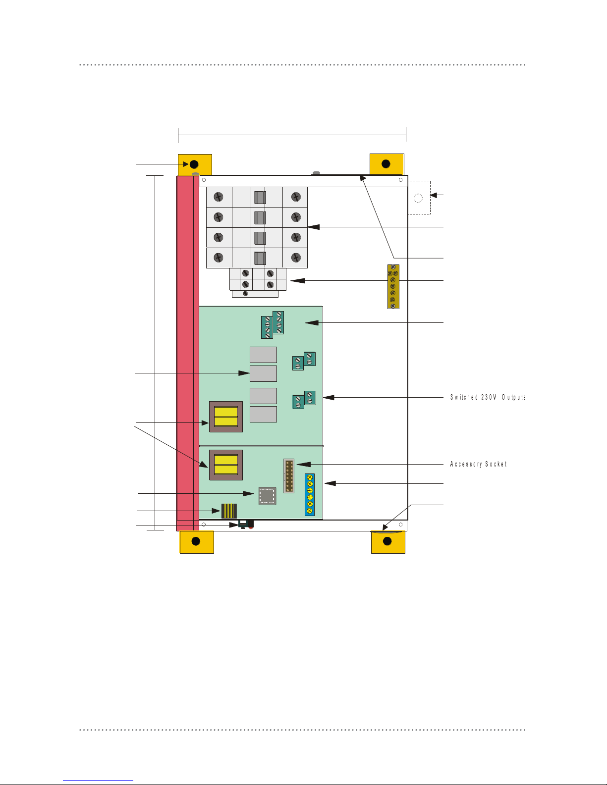
internal view
DBC410 Installation Manual Rev K.docx 3
Alternative Mounting
Point to Enable Easy
Cable Access
1-10V & DSI
Control Outputs
Circuit Breakers &
Emergency Lighting
Line Outputs
40A Supply
Connections
Knock Out For
Low Voltage Cable
Entry Glands
for Load Cables
225mm
320mm
DyNet Network
Connections
Control CPU
Relays
Mounting Point
Network Socket
Service Switch
EARTH LINK
Depth 75mm
Transformer
SHEILD GND D+
D - +12V AUX
0V
CH 1
CH 2
CH 3
CH 4
N1
N2
N3
N4
LINE 4
LINE 3
LINE 2
LINE 1
For spare parts, please call your nearest Dynalite Customer Service Centre, and specify DBC410
Page 4

mounting
4 DBC410 Installation Manual Rev K.docx
Select a Suitable Location
This device is designed for indoor use only. If
installing in an external location, the DBC410
must be housed in a suitable well-ventilated
enclosure. Choose a dry location, that will be
accessible after the installation is complete.
The DBC410 should be mounted vertically,
the right way up. The DBC410 requires an
air gap of 100mm on each side and at the top
and bottom of the device. This air gap is
required to ensure serviceability of the
DBC410 without complete removal from the
mounting surface. This device may emit
some mechanical noise. Take this into
account when deciding the mounting location.
Fixing the Device
The DBC410 has four mounting brackets that
attach to the rear of the enclosure. The
brackets are designed to accommodate 4
fixing screws up to 8mm diameter. The
DBC410 can be fixed to the wall without
opening the cabinet or removing covers.
Make sure no dust or other debris enters the
device during installation. Do not leave the
front cover off for any length of time.
Excessive dust and dirt can degrade the
cooling of internal components.
Allow for Cable Entry
Supply, load and load control cables enter the
enclosure at the top. If these cables are fed
from below the mounting position, they
should be routed around the enclosure to
enter at the top. An alternative method is to
stand the enclosure off from the mounting
surface by mounting it on a cable tray or a
Unistrut style product. The cables can then
be routed between the enclosure and the
mounting surface, and enter the enclosure via
the cutout provided on the mounting face.
The control cables enter at the bottom of the
enclosure. Control cables should never be
run in the mains voltage sections of the
enclosure.
Page 5

supply & load cable connections
DBC410 Installation Manual Rev K.docx 5
Supply Cables
The supply input terminals are located toward
the top of the enclosure and consists of
Earth, Neutral, and Phase, all of which will
accept up to 10mm2 cables. The supply
cables should have a capacity of 40A, to
allow the device to be loaded to its maximum
capacity.
Load Cables
Load cables can be terminated on the 8 way
Load terminal strip (one Phase and one
Neutral for each Channel), and an Earth link
located at the centre of the enclosure. These
connectors will accept up to 6mm2 cables. It
is important that an individual Output Circuit
is not overloaded. Calculate the intended
load, and ensure that it is below the
maximum capacity of an individual channel,
which is 10A. To ensure compliance with
interference standards, the load neutral
cables must be individually connected to the
neutral terminals inside the cabinet. Never
use a common neutral at a remote location.
Load Control Cables
Load control cables can be terminated on the
2 x 4 way terminal strips located directly
above the Load terminals. The left terminal
block is the output for 0 to +10V, or DSI if
selected by software setup. Note that most
types of 1-10V HF Fluorescent Ballast control
wiring is polarity conscious. The + terminal of
the ballast connects to the left terminal block,
and the - terminal connects to the right
(common) terminal block. DSI ballasts are
not polarity conscious.
Emergency Lighting Connections
Connect emergency lighting circuit active to
the load side on the circuit breaker for the
relevant channel, as indicated by the labels
next to the circuit breakers. Do not remove
any cables that may already be terminated at
this location.
Energising the Device
If it is necessary to energise load circuits
before any control cables are connected, it
is acceptable to replace the cover and
energise the device immediately, as the
default factory programming is to have all
channels set to 100% output. If there is no
output on any or all channels, see the
Troubleshooting section (page 8). The
device should be de energised before
terminating the control and data cables.
Page 6

connecting serial control cables
6 DBC410 Installation Manual Rev K.docx
Determine Your Requirements
Serial Ports are used to interconnect other
dimmers, smart control panels, sensors and
AV controllers. Serial port devices can be
identified by 4 terminals, labelled: GND,
DATA+, DATA-, +VE.
Serial Cable Connections
There is one RS485 port for DyNet signals, in
the form of a RJ12 socket, on the front panel,
which is used for the temporary connection of
a PC or a Portable Programmer. There are
data terminals on the control card, for
permanent connections. The recommended
cable for connections to the serial port is
screened, stranded RS485 data cable with
three twisted pairs. Recommended cable
types include:
Belden: 9503
Dynalite: DYNET-STP-CABLE
Garland: MCP3S
Hartland: HCK603
M&M Cable: B2003CS
M&M Cable: B9503CS
Multicables: AWM E120236 2092 20
RS Components: 368-687
One pair is paralleled for GND, one pair paralleled for +VE,
and one pair used for DATA+ and DATA-.
Recommended Cable Colour Coding
Green/White pair paralleled for GND
Orange/White pair paralleled for +VE
Blue/White pair Blue for DATA+
White for DATABrown/White pair Spare or for Join
The colour-coding scheme used is not critical,
as long as the same scheme is used
throughout the installation.
Serial Cable Connecting Method
The recommended connecting method is to
‘daisy chain’ devices (ie. starting at the first
device, then looping in then out of devices,
with a single cable terminating at the last
device. There should not be any spurs or
stubs, and only the first and last device
should terminate 1 cable, all other devices
should terminate 2 cables). Devices may be
wired in any order. The Data Cable should
be segregated from any Mains Cables by
30mm. A data cable that is connected to an
energised dimmer is live. Do not cut or
terminate live data cables. If the data cable
has to cross over any mains cables, it should
do so at a 90° angle.
Connect Data Cable in a ‘Daisy Chain’
RJ12 Socket Connections
Serial Cable Permanent Connections
Page 7

DBC410 Installation Manual Rev K.docx 7
AUX Input - This is a dry contact interface that is active low. The dry contact is connected between the AUX
and GND terminals on the DyNet connector strip. The function of the AUX input is programmable. Ensure
that the cable length between the dry contact and terminal strip is no longer than 2 metres.
Service LED - The Service LED has 3 signalling modes, which are useful for troubleshooting:
Blinking slowly (1Hz) = Normal Operation
Blinking fast (4Hz) = Network Activity Detected
On = Fault
Service Switch - The Service Switch has three functions:
1 push = Transmit Network ID
3 pushes = All Channels 100%
Push & hold for 4 sec = Reboot
Top Set - This adjusts the maximum output that all other control sources can select, ie: if the Top Set is fully
clockwise, 100% selected by a control source will give 100% output. If it is fully anti-clockwise, 100%
selected by a control source will give 50% output. This control is useful for extending lamp life and can be
operated without any form of network control, effectively turning the device into a stand-alone power
conditioner and lamp protector.
Accessory Module Socket - Accepts plug in modules for optional features such as DMX512 ports and Time
clocks. Consult your distributor for details on the available accessory modules.
Page 8

troubleshooting
8 DBC410 Installation Manual Rev K.docx
Check the following list. If you are still unable to rectify the situation, contact your nearest Dynalite office. A
complete list of distributors worldwide can be found on the Internet at: www.philips.com/dynalite
Please ensure that you have completed the following prior to calling our technical support department.
Check all symptoms in the Troubleshooting list
Check for any deviations between the installation and the installation instructions
Make a list of the model numbers of all devices used in the system
SYMPTOM
PROBABLE CAUSE
ACTION
Dimmer does not operate at all. No Service LED
activity. Power supply indicator LED on PCB not lit.
Incorrect connection of Mains supply, or no
power available.
Check power supply to dimmer. Check Line and
Neutral input connections.
Power supply indicator LED lit, but no Service LED
activity.
Supply voltage too low, short circuit on
network. Control PCB faulty.
Check supply voltage is at least 75% of rated
voltage. Check 5V & 12V terminal voltages, 5V
supply must be present. Disconnect network bus
and restore power. Replace control PCB.
Dimmer will not respond to control panel push
buttons.
Control panel incorrectly wired or incorrect
configuration.
Check operation of LEDs on control panel. Push
button on panel and study response of service
LED.
Dimmer operates properly but circuit breakers keep
tripping.
Instant tripping: - short circuit on load.
Delayed tripping: - Dimmer overloaded.
Check load wiring for short circuits.
Verify dimmer loading with current tester (don’t
forget to de-rate for low power-factor loads and
transformer losses). Check that the breaker
terminals are tight.
Fluorescent lights won’t dim.
Wrong type of ballast or ballast incorrectly
wired. Control cable from DBC410 to ballasts
not installed.
Check ballast type. Check actual wiring against
ballast manufacturer’s diagram. Check 1-10V/DSI
cable and settings.
specification
Supply:
230V ±14% 50/60Hz Single Phase at 40A
Outputs:
4 x switched outputs at 10A
4 x signal control outputs, selectable to 1-10VDC and DSI
Optional Maintained Output:
1 x Maintained NC output for testing battery packs in fixtures (fed from MCB A, total load
maintained output & Ch 1 is 10A)
Protection:
4 x 10A single pole thermal magnetic circuit breakers
Switching Device:
Relay 12A nom. (resistive) 120A surge
Control Inputs:
1 x RS485 DyNet serial port
1 x programmable dry contact AUX input
User Controls:
Service Switch
Diagnostic LED
Internal Controls:
Programmable Logic Controller
Dynalite Accessory Module enabled
DyNet DC Supply +VE:
90mA (supply for approx. 4 Smart Panels)
Preset Scenes:
170
Supply Terminals:
Line, Neutral – 2 x 4mm2 max conductor size
Output Terminals:
Line, Neutral for each channels 1-8
2 x 4mm2 max conductor size
Earth link bar provided
0V/DSI , +V/DSI for each channel
1 x 2.5mm2 max conductor size
Cable Entries:
Mains – 1 x 75mm x 53mm removable gland plate
Data – 1 x 25mm dia. knockout
Diagnostic Functions:
Device Online/Offline status
Circuit breaker trip reporting (optional)
Circuit run time tracking (optional)
Compliance:
CE, C-Tick
Construction:
Alloy/Steel wall mount case with epoxy finish
Dimensions:
Height 320mm x Width 225mm x Depth 75mm (excludes wall brackets)
Weight:
4.0 Kilograms
DBC410 Installation Manual Rev K.doc Specifications and design subject to change without notice.
Dynalite Manufactured by WMGD Pty Ltd (ABN 33 097 246 921). All rights reserved. Dynalite, Dimtek, DyNet and DLight and associated logos are the registered
trademarks of Dynalite Intelligent Light Pty Ltd. Not to be reproduced without permission.
Unit 6, 691 Gardeners Road Mascot NSW 2020 Australia Tel: +61 2 8338 9899 Fax: +61 2 8338 9333
E-mail: dynalite.info@philips.com Web: Philips.com/dynalite
 Loading...