

Page 1

ADSL2+ Wireless Modem Router
User Manual
RTA1025W
Page 2

U – RTA1025W
ADSL Router
User’s Manual
Version 2.4
Mar. 3, 2007
Page 3

A
DSL Router User Manual
CCooppyyrriigghhtt NNoottiiccee
© 2005 All rights reserved. No part of this document may be reproduced or transmitted in any form or
by any means, electronic or mechanical, for any purpose, without the express written permission of
the seller.
DDiissccllaaiimmeerr
Information in this document is subject to change without notice. The statements, configurations,
technical data, and recommendations in this document are believed to be accurate and reliable, but
are presented without express or implied warranty. The seller therefore assumes no responsibility and
shall have no liability of any kind arising from the supply or use of this document or the material
contained herein.
SSttaatteemmeenntt ooff CCo
In the interest of improving internal design, operational function, and/or reliability, the seller reserves
the right to make changes to the products described in this docum ent without notice.
The seller does not assume any liability that may occur due to the use or application of the product(s)
or circuit layout(s) described herein.
In addition, the program and information contained herein are licensed only pursuant to a license
agreement that contains restrictions on use and disclosure (that may incorporate by reference certain
limitations and notices imposed by third parties).
onnddiittiioonnss
TTrraaddeemmaarrkkss
All other product or service names mentioned in this document may be trademarks of the comp anies
with which they are associated.
II
Page 4

SSaaffeettyy aanndd PPrreeccaauuttiioonn
For Installation
For Using
Use only the type of power source indicated on the marking labels.
Use only power adapter supplied with the product.
Do not overload wall outlet or extension cords as this may increase the
risk of electric shock or fire. If the power cord is frayed, replace it with a
new one.
Proper ventilation is necessary to prevent the product overheating. Do
not block or cover the slots and openings on the device, which are
intended for ventilation and proper operation. It is recommended to
mount the product with a stack.
Do not place the product near any source of heat or expose it to direct
sunlight.
Do not expose the product to moisture. Never spill any liquid on the
product.
Do not attempt to connect with any computer accessory or electronic
product without instructions from qualified service personnel. This may
result in risk of electronic shock or fire.
Do not place this product on unstable stand o r table.
Power off and unplug this product from the wall outlet when it is not in
use or before cleaning. Pay attention to the temperature of the power
adapter. The temperature might be high.
After powering off the product, power on the product at least 15
seconds later.
Do not block the ventilating openings of this product.
When the product is expected to be not in use for a period of time,
unplug the power cord of the product to prevent it from the damage of
storm or sudden increases in rating.
For Service Do not attempt to disassemble or open covers of this unit by yourself. Nor
should you attempt to service the product yourself, which may void the user’s
authority to operate it. Contact qualified service personnel under the following
conditions:
If the power cord or plug is damaged or frayed.
If liquid has been spilled into the product.
If the product has been exposed to rain or water.
If the product does not operate normally when the operating instructions
are followed.
If the product has been dropped or the cabinet has been damaged.
If the product exhibits a distinct change in performance.
Caution
Any changes or modifications not expressly approved by the party
responsible for compliance could void the authority to operate
equipment.
III
Page 5

A
DSL Router User Manual
FFCCCC
This equipment must be installed and operated in accordance with provided
instructions and a minimum 20 cm spacing must be provided between computer
mounted antenna and person’s body (excluding extremities of hands, wrist and feet)
during wireless modes of operation.
FFCCCC CCllaassss BB NNoottiiccee
This device complies with Part 15 of the FCC Rules. Operation is subject to the
following two conditions:
(1) this device may not cause harmful interference;
(2) this device must accept any interference received, including interference that
may cause undesired operation.
Note:
This equipment has been tested and found to comply with the limits for a Class B
digital device, pursuant to Part 15 of the FCC Rules. These limits are designed to
provide reasonable protection against harmful interference in a residential
installation. This equipment can generate, use and radiate radio frequency energy
and, if not installed and used in accordance with the instructions, may cause harmful
interference to radio communications. However, there is no guarantee that
interference will not occur in a particular installation. If this equipment does cause
harmful interference to radio or television reception, which can be determined b y
turning the equipment off and on, the user is encouraged to try to correct the
interference by one or more of the following measures:
z Reorient or relocate the receiving antenna.
z Increase the separation between the equipment and receiver.
z Connect the equipment into an outlet on a circuit different from that to which
the receiver is connected.
z Consult the dealer or an experienced radio/television technician for help.
IV
Page 6

Contents
Contents
Before You Use.......................................................................................... IX
Unpacking .....................................................................................................IX
Features........................................................................................................IX
ADSL Compliance....................................................................................IX
ADSL2 Compliance ..................................................................................IX
ADSL2+ Compliance.................................................................................IX
Wireless LAN Compliance ...........................................................................X
ATM Features..........................................................................................X
Bridging Features......................................................................................X
Routing Features .....................................................................................XI
Security Features.....................................................................................XI
Configuration and Management....................................................................XI
Subscription for ADSL Service.............................................................................XII
Chapter 1: Overview .....................................................................................1
Physical Outlook...............................................................................................1
Front Panel.............................................................................................1
Rear Panel .............................................................................................2
Chapter 2: System Requirement and Installation ......................................................3
System Requirement..........................................................................................3
Choosing a place for the ADSL Router.....................................................................3
Connecting the ADSL Router ................................................................................4
USB Driver Installation........................................................................................5
For Windows ME ......................................................................................5
For Windows 2000 ....................................................................................5
For Windows XP.......................................................................................7
For Windows Vista .................................................................................. 10
Uninstalling the USB Driver ................................................................................ 18
For Windows ME .................................................................................... 18
For Windows 2000 .................................................................................. 18
For Windows XP.....................................................................................22
For Windows Vista .................................................................................. 24
Setting up TCP/IP ........................................................................................... 29
For Windows 98 ..................................................................................... 29
For Windows ME .................................................................................... 32
For Windows NT.....................................................................................34
For Windows 2000 .................................................................................. 37
For Windows XP.....................................................................................40
For Windows Vista .................................................................................. 43
Renewing IP Address on Client PC....................................................................... 46
For Windows 98/ME................................................................................. 46
For Windows NT/2000/XP.......................................................................... 47
For Windows Vista .................................................................................. 49
Chapter 3: Accessing the Internet .................................................................... 51
PPP over ATM (PPPoA) Mode ............................................................................ 52
PPP over ATM (PPPoA) IP Extension Mode ............................................................ 53
PPP over Ethernet (PPPoE) Mode........................................................................54
PPP over Ethernet (PPPoE) IP Extension Mode........................................................ 55
Numbered IP over ATM (IPoA) ............................................................................ 56
V
Page 7

ADSL Router User Manual
Numbered IP over ATM (IPoA)+NAT ..................................................................... 58
Unnumbered IP over ATM (IPoA) ......................................................................... 60
Unnumbered IP over ATM (IPoA)+NAT .................................................................. 62
Bridge Mode.................................................................................................. 64
MER ........................................................................................................... 65
Chapter 4: Web Configuration....................................................................... 67
Using Web-Based Manager................................................................................67
Outline of Web Manager............................................................................ 68
To Have the New Settings Take Effect........................................................... 68
Language............................................................................................. 68
Quick Start.................................................................................................... 69
Connect to Internet.................................................................................. 69
Quick Setup .......................................................................................... 69
Connection Type..................................................................................... 70
PPP over ATM/ PPP over Ethernet............................................................... 70
IP over ATM......................................................................................... 73
Bridging ............................................................................................... 75
Status.......................................................................................................... 77
Overview.............................................................................................. 77
ADSL Line ............................................................................................ 78
Internet Connection ................................................................................. 79
Traffic Statistics...................................................................................... 79
DHCP Table..........................................................................................79
Wireless Clients...................................................................................... 79
Routing Table ........................................................................................ 79
ARP Table............................................................................................ 79
Advanced Setup ............................................................................................. 80
Local Network – IP Address ....................................................................... 80
Local Network – DHCP Server .................................................................... 81
Local Network – UPnP.............................................................................. 82
Local Network – IGMP Snooping.................................................................. 82
Internet – Connections.............................................................................. 84
Internet – DNS Server .............................................................................. 87
Internet – IGMP Proxy .............................................................................. 87
Internet – ADSL......................................................................................88
IP Routing – Static Route .......................................................................... 89
IP Routing – Dynamic Routing..................................................................... 90
Virtual Server – Port Forwarding .................................................................. 91
Virtual Server – Port Triggering.................................................................... 93
Virtual Server – DMZ Host ......................................................................... 94
Virtual Server – Dynamic DNS .................................................................... 94
Virtual Server – Static DNS ........................................................................ 95
NAT ALG Configuration ............................................................................ 96
Firewall – Bridge Filtering .......................................................................... 97
Firewall – IP Filtering................................................................................ 98
Quality of Service – Bridge QoS................................................................. 102
Quality of Service – IP QoS...................................................................... 103
Port Mapping....................................................................................... 105
Wireless..................................................................................................... 107
Basic Settings...................................................................................... 107
Security ............................................................................................. 109
Access Control..................................................................................... 115
Repeater............................................................................................ 116
Management ............................................................................................... 117
Diagnostics......................................................................................... 117
VI
Page 8

Contents
Management Accounts ........................................................................... 118
Management Control – From Remote.......................................................... 118
Management Control – From Local............................................................. 119
TR-069 Client Configuration ..................................................................... 119
Internet Time ....................................................................................... 122
System Log......................................................................................... 123
Backup Config ..................................................................................... 127
Update Firmware .................................................................................. 128
Reset Router....................................................................................... 128
UPnP for XP........................................................................................ 129
Chapter 5: Troubleshooting........................................................................ 131
Problems with LAN ........................................................................................ 131
Problems with WAN....................................................................................... 131
Problems with Upgrading................................................................................. 132
Chapter 6: Glossary.................................................................................. 133
Appendix A: Specifications ........................................................................ 135
Appendix B: Client Setup for 802.1x, WPA, and WPA-PSK.................................137
Retreiving Client Certificate...................................................................... 137
Enabling 802.1x Authentication and Security.................................................. 140
Enabling WPA Authentication and Security.................................................... 143
Enabling WPA-PSK Authentication and Security ............................................. 145
VII
Page 9

ADSL Router User Manual
VIII
Page 10

Before You Use
Before You Use
Thank you for choosing the Asymmetric Digital Subscriber Line (ADSL) Router. With
the asymmetric technology, this device runs over standard copper phone lines. In
addition, ADSL allows you to have both voice and data services in use
simultaneously all over one phone line.
RTA1025W Wireless ADSL2+ Router is a DSL broadband access device which
allows ADSL connectivity while providing 802.11g wireless LAN capabilities for home
or office users. It supports ADSL2/ADSL2+ and is backward compatible to ADSL,
even offers auto-negotiation capability for different flavors (G.dmt, G.lite, or T1.413
Issue 2) according to central office DSLAM’s settings (Digital Subscriber Line Access
Multiplexer). Also the feature-rich routing functions are seamlessly integrated to
ADSL service for existing corporate or home users. Now users can enjoy various
bandwidth-consuming applications via RTA1025W Wireless ADSL2+ Router.
Unpacking
Check the contents of the package agai nst the pack contents checklist below. If any
of the items is missing, contact the dealer from whom the equipment was
purchased.
9 ADSL Router
9 Power Adapter and Cord
9 USB Cable
9 RJ-11 ADSL Line Cable
9 RJ-45 Ethernet Cable
9 Quick Start Guide
9 Driver & Utility Software CD
Features
ADSL Compliance
³ ANSI T1.413 Issue 2
³ ITU G.992.1 Annex A (G .dmt)
³ ITU G.992.2 Annex A (G .lit e)
³ ITU G.994.1 (G.hs)
³ Support dying gasp
³ Maximum Rate: 8 Mbps for downstream and 1 Mbps for upstream
ADSL2 Compliance
³ ITU G.992.3 Annex A (G .dmt.bis)
³ Support dying gasp
³ Maximum Rate: 12 Mbps for downstream and 1 Mbps for upstream
ADSL2+ Compliance
³ ITU G.992.5 Annex A
IX
Page 11

ADSL Router User Manual
³ Support dying gasp
³ Maximum Rate: 24 Mbps for downstream and 1.2 Mbps for upstream
Wireless LAN Compliance
³ IEEE 802.11g and IEEE 802.11b
³ Data Rate: 54, 48, 36, 24, 18, 12, 9, 6 Mbps for 802.11g; 11, 5.5, 2, 1 Mbps for
802.11b
³ Modulation Tech nique: OFDM for 802.11g; CCK (11 Mbps, 5.5 Mbps) for
802.11b; DQPSK (2Mbps) for 802.11b; DBPSK (1 Mbps) for 802.11b
³ Network Architecture: infrastructure
³ Operating Frequency: 2.4 ~ 2.5 GHz
³ Operating Channels: depending on local regulations. For example, 11
Channels (Northern America), 13 Channels (Europe), and 14 Channels (Japan)
³ Support the selection of best quality channel automatically
³ RF Output Power: 13.5+/-1.5dBm for 802.11g; 17.5+/-1.5dBm for 802.11b
³ Antenna Connectors: Hardware diversity support. One external antenna and
one internal antenna are provided.
³ Coverage Are a: 300 meters
³ Support WEP (Wired Equivalent Privacy) mechanism which use s RC4 with
64-bit or 128-bit key length
³ Support 802.1x and WPA/WPA2
³ Support the Access Control function: onl y registered WLAN clients are allowed
to associate to this device.
³ SSID can be hidden for the security issue (Don’t broadcast SSID).
³ Two SSIDs are supported currently. One SSID can be used for main wireless
network and the other SSID can be used for guest wireless network. Two
wireless networks can be configured in different wir e less security level.
³ Support the Repeater function to extend the coverage area
³ Support wireless user isolation for the hotspot
³ Support Wireless QoS (WMM)
ATM Features
³ Compliant to ATM Forum UNI 3.1 / 4.0 Permanent Virtual Circuits (PVCs)
³ Support up to 16 PVCs for UBR, CBR, VBR-nrt, VBR-rt with traffic shaping
³ RFC2684 LLC Encapsulation and VC Multiplexing over AAL5
³ RFC2364 Point-to-Point Protocol (PPP) over AAL5
³ RFC2225 Classical IP and ARP over ATM
X
³ RFC2516 PPP over Ethernet: support Relay (Transparent Forwarding) and
Client functions
³ Support PPPoA or PPPoE Bridged mode (the IP address got from ISP can be
passed to the user’s PC and behave as the IP address of the user’s PC.)
³ OAM F4/F5 End-to-End/Segment Loopback Cells
Bridging Features
³ Supports self-learning bridge specified in IEEE 802.1d Transparent Bridging
Page 12

Before You Use
³ Supports up to 4096 learning MAC addresses
³ Transparent Bridging amo ng 10/100 Mb Ethernet, USB, and 802.11g wireless
LAN
³ Supports IGMP Snooping
³ Supports 802.1Q VLAN packet pass-through
Routing Features
³ NAT (Network Address Translation) / PAT (Port Address Translation) let
multiple users on the LAN to access the internet for the cost of only one IP
address.
³ ALGs (Application Level Gateways): such as NetMeeting, MSN Messenger,
FTP, Quick Time, mIRC, Real Player, CuSeeMe, VPN pass-through with
multiple sessions, RTSP, SIP, etc.
³ Port Forwarding: the users can setup multiple virtual servers (e.g., Web, FTP,
Mail servers) on user’s local network.
³ Support DMZ
³ UPnP IGD (Internet Gateway Device) with NAT traversal capability
³ Static routes, RFC1058 RIPv1, RFC1723 RIPv2
³ DNS Relay, Dynamic DNS
³ DHCP Client/Relay/Server
³ Time protocol can be used to get current time from network time server
³ Support IGMP Proxy
³ Support port mapping function which allows you to assign all data traffic
transmitted among specific Internet connections and LAN ports
³ Support IP/Bridge QoS for prioritize the transmission of dif f erent traffic classes
³ Support 802.1Q VLAN Tagging
Security Features
³ PAP (RFC1334), CHAP (RFC1994), and MS-CHAP/MS-CHAP2 for PPP
session
³ Firewall support IP packets filtering based on IP address/Port number/Protocol
type
³ Bridge packet filtering (optional)
³ URL filtering (optional)
³ Support DoS (Deny of Services) which detect & protect a number of attacks
(such as SYN/FIN/RST Flood, Smurf, WinNuke, Echo Scan, Xmas Tree Scan,
etc)
Configuration and Management
³ User-friendly embedded web configuration interface with password protection
³ Remote management accesses control
³ Telnet/SSH session for local or remote management
³ Firmware upgrades through HTTP, TFTP, or FTP
³ The boot loader contains very simple web page to allow the users to update
the run-time firmware image.
³ Configuration file backup and restore
XI
Page 13

ADSL Router User Manual
³ Support TR-069, TR-11 1, and TR-0981
Subscription for ADSL Service
To use the ADSL Router, you have to subscribe for ADSL service from your
broadband service provider. According to the service type you subscribe, you will get
various IP addresses:
Dynamic IP: If you apply for dial-up connection, you will be given an Internet
account with username and password. You will get a dynamic IP by dialing up to
your ISP, such as under PPPoA, PPPoE, or MER mode.
Static IP address: If you apply for full-time connectivity, you may get either one
static IP address or a range of IP addresses from your ISP. The IP address varies
according to different ADSL service pro v ider, such as using IPoA or MER mode.
Notes and Cautions
Note and Caution in this manual are highlighted with graphics as below to indicate
important information.
Note
Caution
Contains information that corresponds to a specific topic.
Represents essential steps, actions, or messages that should not be
ignored.
1
TR-098 can be supported since April, 2007.
XII
Page 14

Chapter 1: Overview
Chapter 1: Overview
This chapter provides you the description for the LEDs and connectors on the front
and rear surface of the router. Before you use/install this router, please take a look at
the information first.
Physical Outlook
Front Panel
The following illustration displays the front panel of the ADSL Rout er:
LED Indicators
The ADSL Router is equipped with several LEDs on the front panel as described in
the table below (from right to left):
Function Color Definition
Off Power is off.
Solid Green Power is on and the device operates normally.
Power
DSL
PPP
Ethernet
USB
WLAN
Solid Red
Flash Red Firmware upgrades in progress
Off No DSL signal is detected.
Slow Flash Green DSL line is handshaking in progress
Fast Flash Green DSL line is training in progress
Solid Green DSL line connection is up.
Off No PPPoA or PPPoE connection
Solid Green At least one PPPoA or PPPoE connection is up. The users can
Off No Ethernet signal is detected.
Flash Green User data is going through Ethernet port
Solid Green Ethernet interface is ready to work.
Off No USB signal is detected.
Flash Green User data is going through USB port
Solid Green USB interface is ready to work.
Off No radio signal is detected.
Flash Green User data is going through WLAN port
Solid Green WLAN interface is ready to work.
Power on self-test in progress
The device enters the console mode of the boot loader.
Power on self-test failure if the led always stays solid red.
access the Internet now.
1
Page 15
ADSL Router User Manual
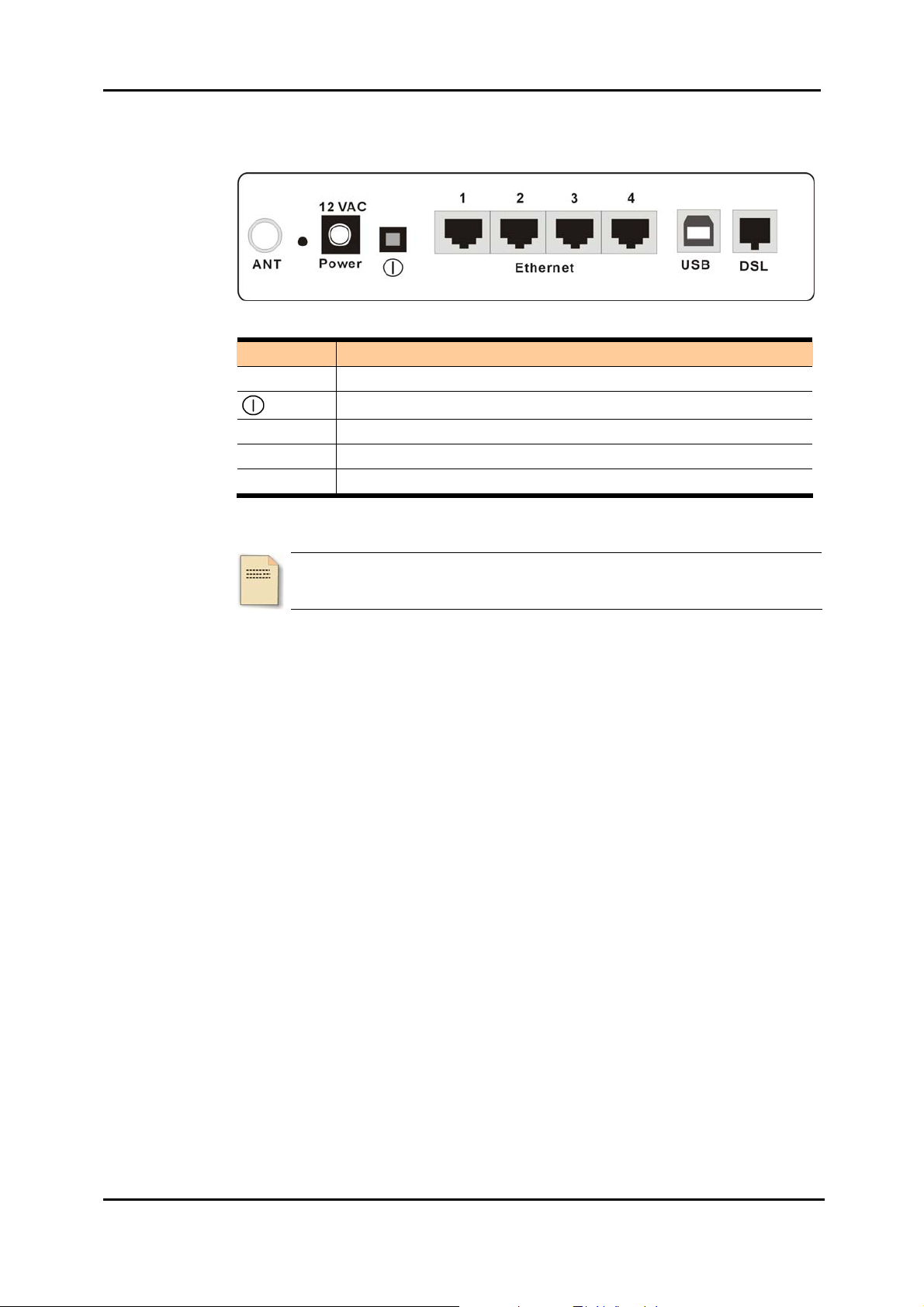
Rear Panel
The following figure illustrates the rear panel of your ADSL Route r:
Connector Description
12VAC
Ethernet 1- 4
USB
DSL
12VAC Power connector
Power switch
Ethernet RJ-45 connector
USB client port
RJ-11 connector
Note: For use only with power supply OEM type AA-121ABN, AA-121AD, AA-121AE;
Leader type A48120100-C5, A48120100-B2, and A48120100-A3.
2
Page 16

Chapter 2: System Requirement and Installation
Chapter 2: System Requirement and Installation
System Requirement
To access the ADSL Router via Ethernet, the host computer must meet the following
requirements:
Equipped with an Ethernet network interface.
Have TCP/IP installed.
Allow the client PC to obtain an IP address automatically or set
a fixed IP address.
With a web browser installed: Internet Explorer 5.x or later.
The ADSL Router is configured with the default IP address of 192.168.1.1 and
subnet mask of 255.255.255.0. Considering that the DHCP server is Enable by
default, the DHCP clients should be able to access the ADSL Router, or the host PC
should be assigned an IP address first for initial configuration.
You also can manage the ADSL Router throu gh a web browser-based manager:
ADSL ROUTER CONTROL PANEL. The ADSL Router manager u se s the HTTP
protocol via a web browser to allow you to set up and manage the device.
To configure the device via web browse r, at least one
properly-configured PC must be connected to the network (either
connected directly or through an external hub/switch to the LAN port of
the device).
Choosing a place for the ADSL Router
n Place the ADSL Router close to ADSL wall outlet and power outlet for the
cable to reach it easily.
o Avoid placing the device in places where people may walk on the cables. Also
keep it away from direct sunlight or heat sources.
p Place the device on a flat and stable stand.
3
Page 17
ADSL Router User Manual
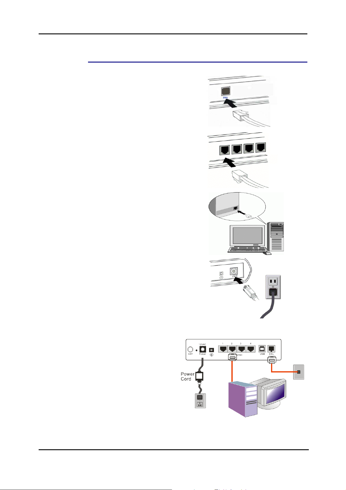
Connecting the ADSL Router
Follow the steps below to connect the related devices.
n Connecting the ADSL line.
Connect the DSL port of the
device to your ADSL wall
outlet with RJ-11 cable.
o Please attach one end of the
Ethernet cable with RJ-45
connector to the LAN port of
your ADSL Router.
p Connect the other end of the
cable to the Ethernet port of
the client PC.
q Connect the supplied power
adapter to the PWR port of
your ADSL Router, and plug
the other end to a power
outlet.
r Turn on the power switch.
Here provides an example for
hardware connection.
4
Page 18
Chapter 2: System Requirement and Installation
USB Driver Installation
If the ADSL router is connected to a PC through the USB interface, you will be
prompted for the USB drivers when plugging the USB cable to the PC. Refer to the
relevant operating system to install the USB drivers.
For Windows ME
n Run the USB installation program from the CD provided in your router
package.
o An InstallShield Wizard will appear. Please wait for a moment.
p When the welcome screen appears, click Next for the next step.
q When the complete window of the InstallShield Wizard appears, cli ck
Finish.
r Link your router and the PC with a USB cable.
s The system will detect the USB driver automatically. Then, the system will
copy the proper files for this router.
Note: If the USB device is not detected automatically, check the USB cable
between the PC and the device. Besides, verify that the device is power on.
t When the file copying finished, the dialog above will close. Now the USB
driver is installed properly. You can use the router.
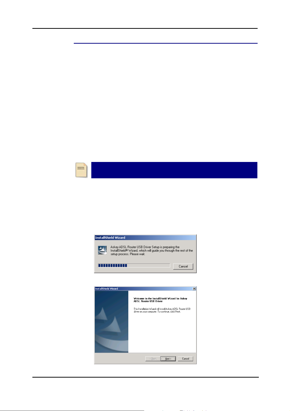
For Windows 2000
n Run the USB installation program from the CD provided in your router
package.
o An InstallShield Wizard will appear. Please wait for a moment.
p When the welcome screen appears, click Next for the next step.
5
Page 19

ADSL Router User Manual
q When the complete window of the InstallShield Wizard appears, click
Finish.
r Link your router and the PC with a USB cable.
s The system will detect the USB driver automatically. And then, the system
will copy the proper files for this router.
Note: If the USB device is not detected automatically, check the USB cable
between the PC and the device. Besides, make sure that the device is
power on.
t When the file copying finished, the dialog above will close. Now the USB
driver is installed properly. You can use the router.
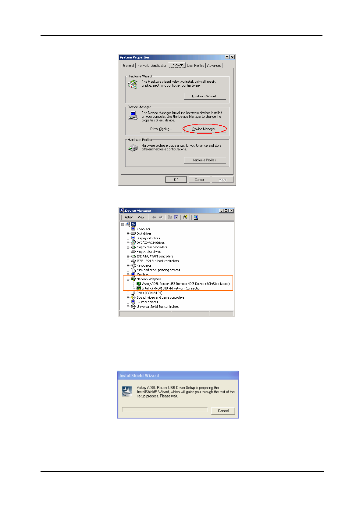
To make sure that your router is properly installed, please do the following steps.
1. Right-click on My Computer and press Properties.
6
Page 20
Chapter 2: System Requirement and Installation
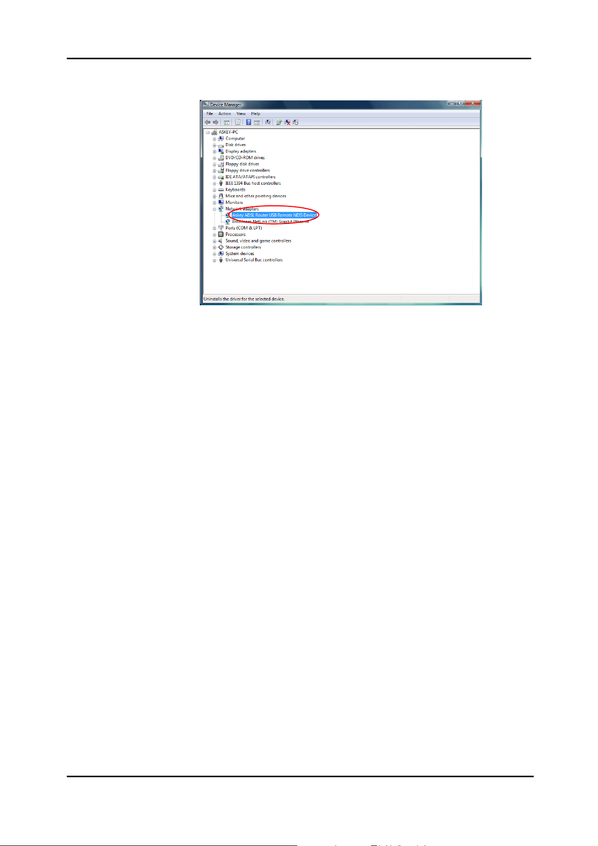
2. On the Hardware tap, click Device Manager.
3. Confirm that the Askey AD SL Router USB Remote NDIS Device is on the
Network adapters list.
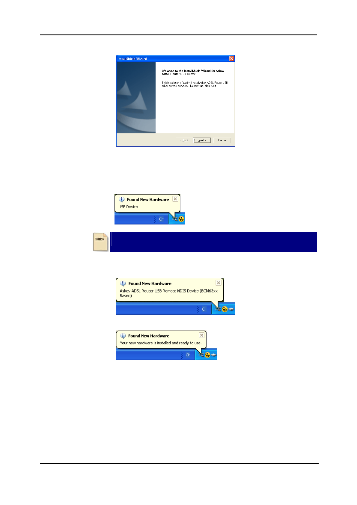
For Windows XP
n Run the USB installation program from the CD provided in your router
package.
o An InstallShield Wizard will appear. Please wait for a moment.
7
Page 21
ADSL Router User Manual
p When the welcome screen appears, click Next for the next step.
q When the finish installing message of InstallShield Wizard appears, click
Finish.
r Link your router and the PC with a USB cable.
s The system will detect the USB driver automatically.
Note: If the USB device is not detected, check the USB cable between the
PC and the device. Also make sure that the device is power on.
t Then the system will try to find the proper driver for your router and copy the
files automatically.
u After the file copying finished, a completing message will appear.
v You can use the wireless router now.
To make sure your router is properly installed, please do the following steps.
8
Page 22

Chapter 2: System Requirement and Installation
1. Right-click on My Computer and press Properties.
2. On the Hardware tab, click Device Manager.
3. Confirm that the Askey ADSL Router USB Remote NDIS Device is on the
Network adapters list.
9
Page 23

ADSL Router User Manual
For Windows Vista
For Vista users, please press Continue whenever a prompted window asking for
permission to continue during USB driver installation process (see the figure below
for example).
To install the USB driver before connect the router to the PC, here provides two
methods.
Method One – Use the driver CD came with the product package.
n Run the USB installation program on the CD provided in your router
package.
o An InstallShield Wizard will appear. Please wait for a moment.
10
p When the welcome screen appears, click Next for the next step.
Page 24

Chapter 2: System Requirement and Installation
q When the complete message of InstallShield Wizard appears, click Finish.
r Link your router and the PC with a USB cable.
s The system will detect the USB driver automatically.
Note: If the USB device is not detected, check the USB cable between the
PC and the device. Also make sure that the device is power on.
t After the file copying finished, a completing message will appear.
u You can use the router now.
11
Page 25

ADSL Router User Manual
Method Two – Run a silent installation.
n Copy the USB driver folder from the driver CD to somewhere on the PC. (In
our example, the driver files are put under D:\Askey ADSL USB WHQLed.)
o Open Start menu, key in cmd in the blank and press enter. Then click cmd.
2
1
p When the Command Prompt screen appears, point to the driver folder on
your PC, and then enter setup -s. Press enter to start silent installation.
q The system will install the driver automatically. You can connect your router
and the PC with a USB cable now .
r The system will detect the USB driver automatically.
Note: If the USB device is not detected, check the USB cable between the
PC and the device. Also make sure that the device is power on.
12
s After the file copying finished, a completing message will appear.
t You can use the router now.
Page 26
Chapter 2: System Requirement and Installation
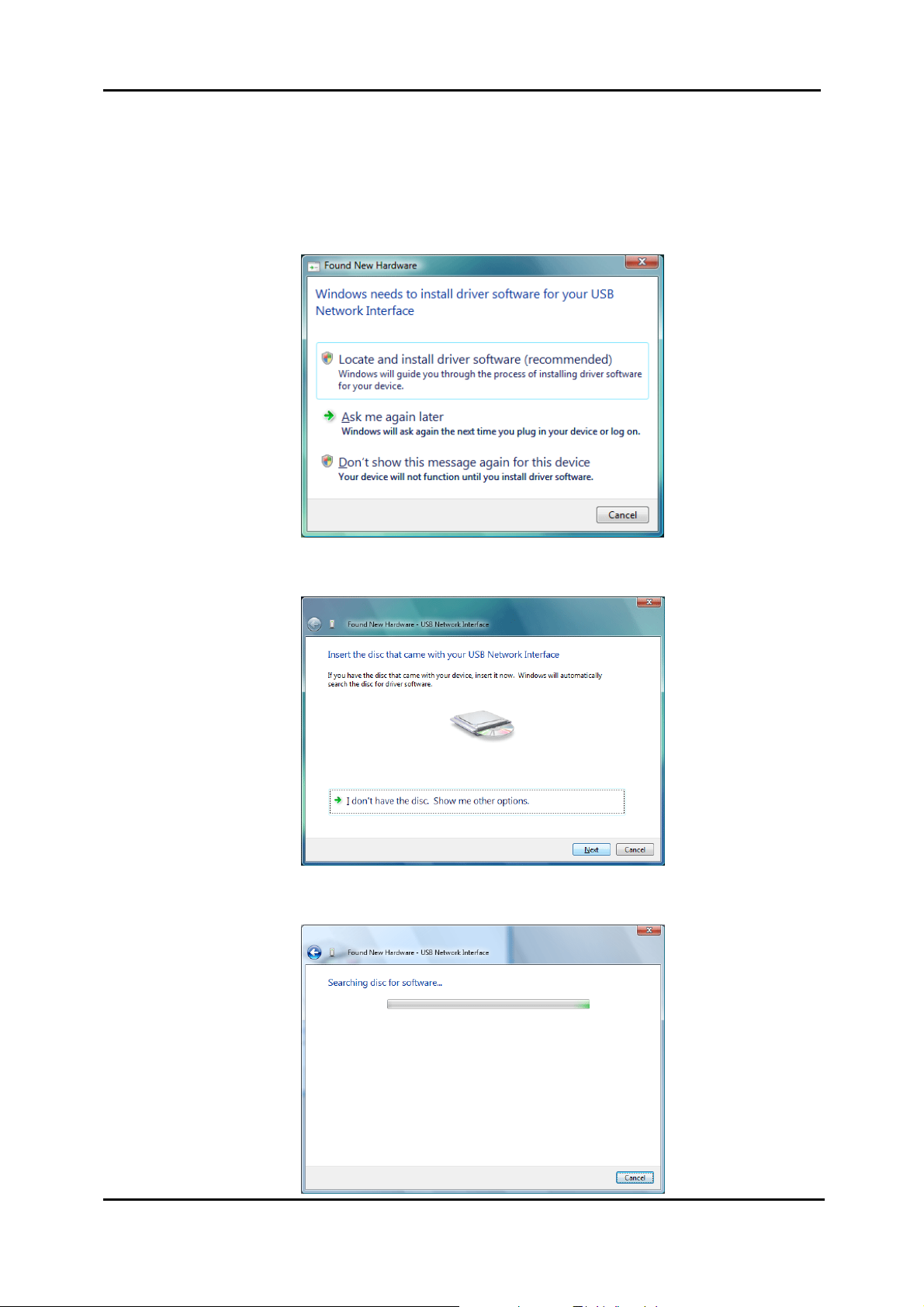
If the USB driver has not been installed yet, you can also connect the router to the
PC with a USB cable and wait for Universal Plug and Play device to detect the router,
and then install the driver.
n Plug the USB cable into the USB port on the PC.
o A Found New Hardware window will appear. Press Locate and install
driver software (recommended).
p Then insert the USB driver CD provided in your router package into the PC,
and press Next.
q The system will search disc for the USB driver needed and then complete
the installation.
13
Page 27
ADSL Router User Manual
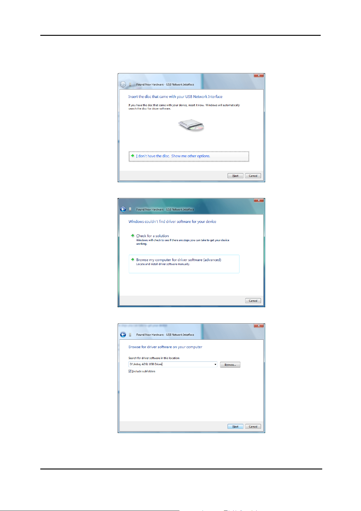
Or if you do not have a disc, but have the driver files on your PC, you can follow the
steps below:
p Press I don’t have the disc. Show me other options.
q Select Browse my computer for driver software (advanced).
14
r Press Browse to set the path for the driver file, and then press Next.
Page 28

Chapter 2: System Requirement and Installation
s Wait while the system installing the driver.
t Now the driver software is installed successfully. Press Close to start using
the router.
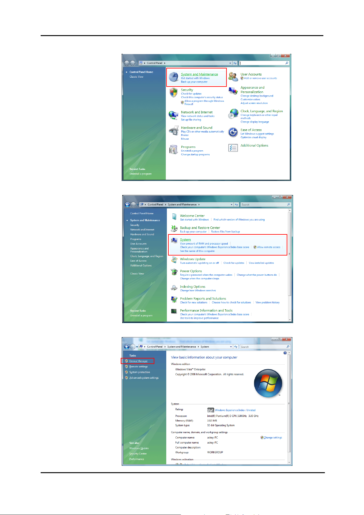
To make sure the USB driver for your router is properly installed, please do the
following steps.
1. Open the Start menu and press Control Panel.
15
Page 29
ADSL Router User Manual
2. On the Control Panel folder, click System and Maintenance.
3. Press System.
4. Click Device Manager.
16
Page 30
Chapter 2: System Requirement and Installation
5. Confirm that the Askey AD SL Router USB Remote NDIS Device is on the
Network adapters list.
17
Page 31

ADSL Router User Manual
Uninstalling the USB Driver
For Windows ME
To uninstall the USB driver, please follow the procedures below.
Method One:
n Unplug the USB cable from the USB port on your PC.
o Choose Programs – Askey Broadband – Uninstall Askey ADSL Router
USB Driver from the Start menu.
p The InstallShield Wizard dialog will appear.
q A dialog appears to confirm whether you really want to remove the USB
driver or not. Please click Ok.
r When the Maintenance Complete screen appears, the USB driver is
removed successfully. Click Finish.
Method Two:
n Unplug the USB cable between your router and your PC. Then click OK.
o Choose Settings –Control Panel from the Start menu. Choose
Add/Remove Programs.
p A dialog appears to ask you to choose the program that you want to remove.
Please select Askey ADSL Router USB Driver and click Change/Remove.
q The InstallShield Wizard dialog will appear.
r When the Maintenance Complete screen appears, the USB driver is
removed successfully. Click Finish
For Windows 2000
To uninstall the USB driver, there are two ways to do it. Please do the following
procedures.
Method One:
n To safely unplug the USB cable from the USB port on your PC:
1. Go to the right lower corner for Unplug and Eject Hardware and left click
on it.
2. Click the dialog for Stop Askey ADSL Router USB Remote NDIS
Device.
18
3. The Router is safely removed, click OK to continue.
Page 32
Chapter 2: System Requirement and Installation
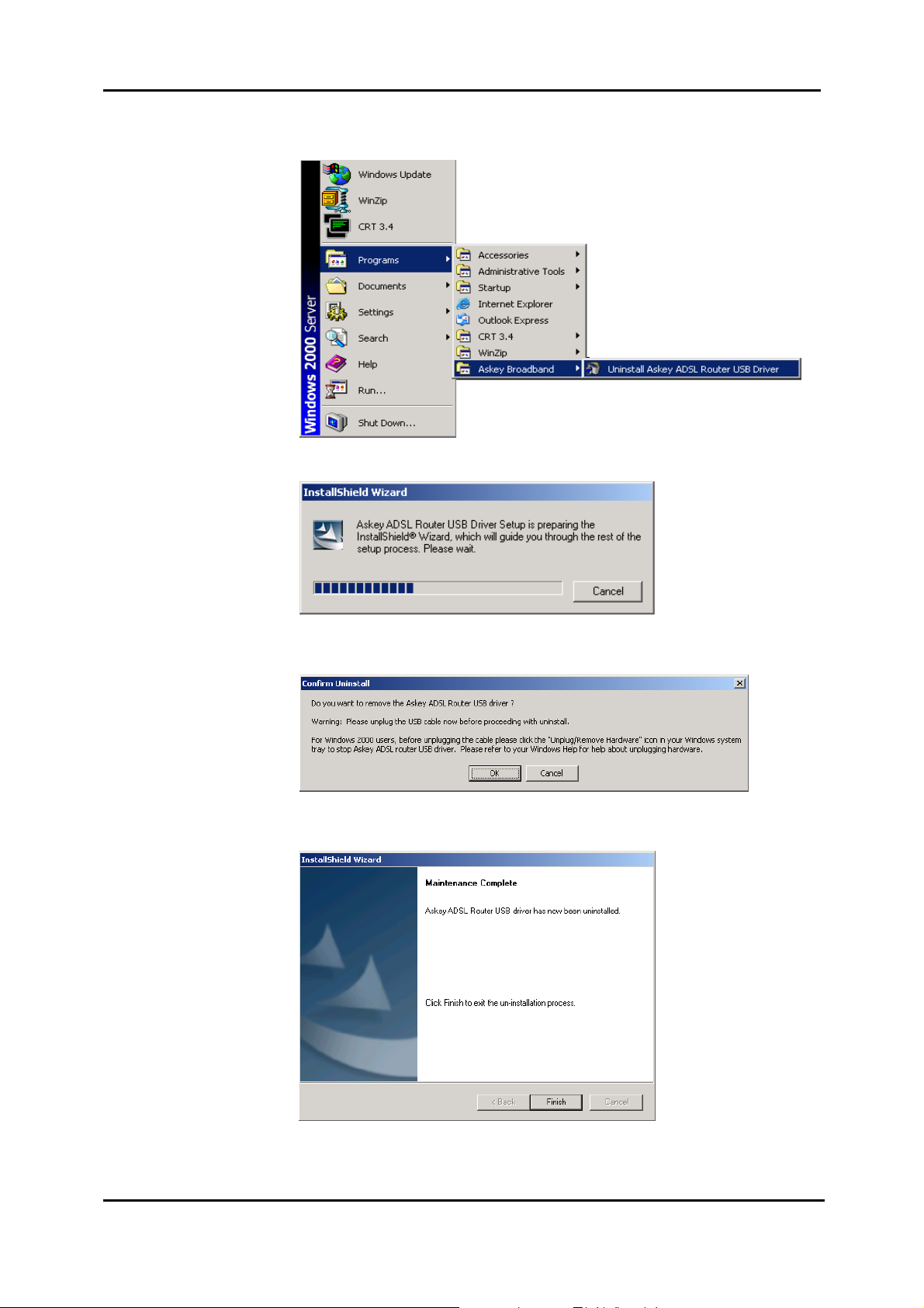
o Choose Programs – Askey Broadband – Uninstall Ask ey ADSL Router
USB Driver from the Start menu.
p The InstallShield Wizard dialog will appear.
q A dialog appe ars to confirm whether you want to remove the USB driver or
not. Please click Ok.
r When the Maintenance Complete screen appears, the USB driver is
removed successfully. Click Finish.
19
Page 33

ADSL Router User Manual
Method Two:
n To safely unplug the USB cable from the USB port on your PC:
1. Go to the right lower corner for Unplug and Eject Hardware and left click
on it.
2. Click the dialog for Stop Askey ADSL Router USB Remote NDIS
Device.
3. The Router is safely removed, click OK to continue.
o Choose Settings – Control Panel from the Start menu. Choose
Add/Remove Programs.
20
p A dialog appears to ask you to choose the program that you want to remove.
Please select Askey ADSL Router USB Driver and click Change/Remove.
Page 34

Chapter 2: System Requirement and Installation
q A Confirm Un install dialog will show up, unplug your device from the USB
port and click OK.
r The InstallShield Wizard will guide you till the USB driver is removed.
s When the Maintenance Complete screen appears, the USB driver is
removed successfully. Click Finish.
21
Page 35

ADSL Router User Manual
For Windows XP
To uninstall the USB driver, there are two ways to do it. Please do as follows.
Method One:
n Unplug your USB cable between your router and your PC.
o Choose Programs – Askey Broadband – Uninstall Ask ey ADSL Router
USB Driver from the Start menu.
p The InstallShield Wizard dialog will appear.
q A dialog appe ars to confirm whether you want to remove the USB driver or
not. Unplug the USB cable from your PC, and click Ok.
r When the Maintenance Complete screen appears, the USB driver is
removed successfully. Click Finish.
Method Two:
22
n Unplug your USB cable between your router and your PC.
Page 36

Chapter 2: System Requirement and Installation
o Choose Settings –Control Panel from the Start menu. Choose Add or
Remove Programs.
p A dialog appears to ask you to choose the program that you want to remove.
Please select Askey ADSL Router USB Driver and click Change/Remove.
q The InstallShield Wizard dialog will appear.
r A dialog appe ars to confirm whether you want to remove the USB driver or
not. Unplug the USB cable from your PC, and click Ok.
s When the Maintenance Complete screen appears, the USB driver is
removed successfully. Click Finish.
23
Page 37

ADSL Router User Manual
For Windows Vista
For Vista users, please press Continue whenever a prompted window asking for
permission to continue during USB driver uninstallation proces s (see the figure
below for example).
To uninstall the USB driver, there are two ways to do it. Please follow the
instructions.
Method One: Remove from Device Manager.
n Choose Start menu, and then select Control Panel.
24
o Click System and Maintenance.
Page 38

Chapter 2: System Requirement and Installation
p Press System.
q Click Device Manager.
r Right click Askey ADSL Router USB Remote NDIS Device on the
Network adapters list, and press Uninstall.
25
Page 39
ADSL Router User Manual
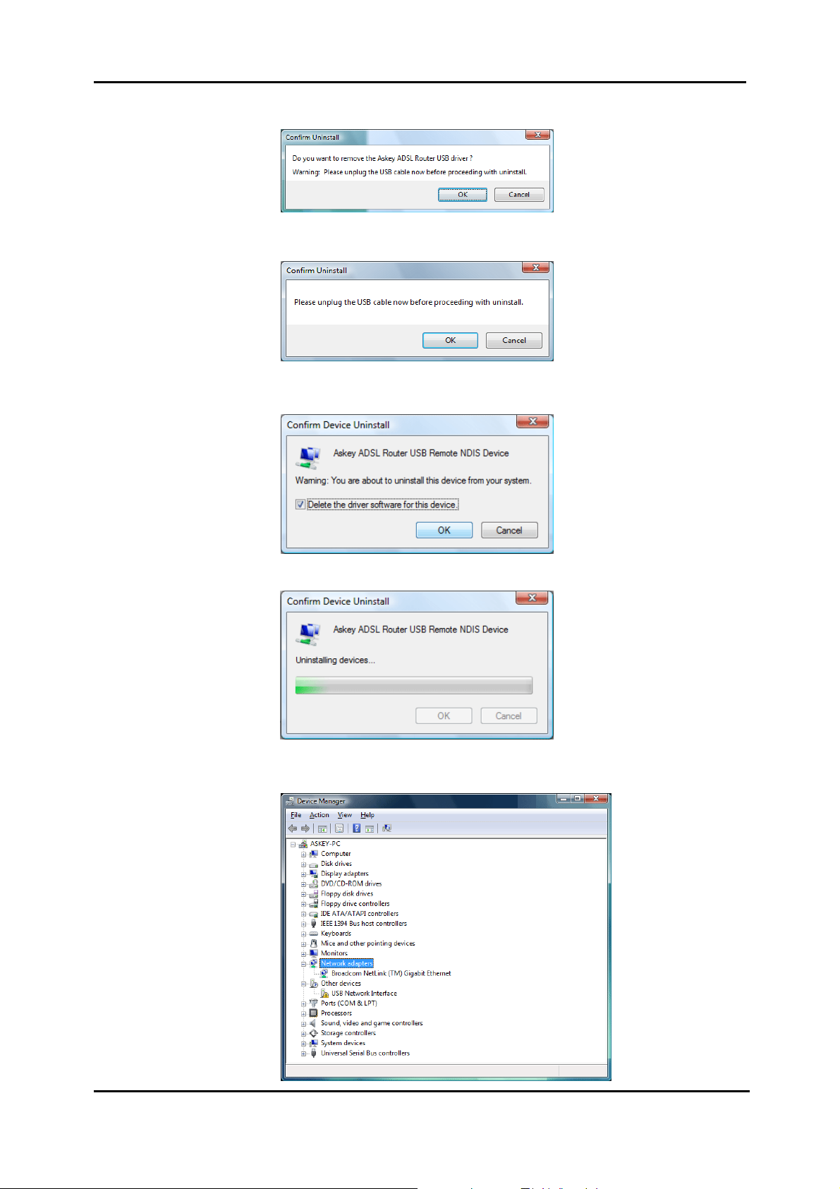
s Click OK when the Confirm Uninstall window appears.
Remember to unplug the USB cable before continue the uninstallation, or
you will see the reminder as follows. Unplug and press OK.
t When the Confirm Device Uninstall screen show up, check Delete the
driver software for the device and cli ck OK to continue.
u Wait while the system is uninstalling.
v When the uninstallation is finished, the icon of this router under network
adapter list will disappear.
26
Page 40

Chapter 2: System Requirement and Installation
Method Two – uninstall from program list
Note: If your USB driver is installed by UPnP device, you can only use method one
(via the Device Manager) to uninstall, because the installed driver will not be shown
on the program list.
n Unplug your USB cable between your router and your PC.
o Choose Start menu, and open Control Panel folder. Click Uninstall a
program.
p If the driver name is not on the list, click Refresh button or F5 to update the
information. To remove the driver, select it, and then press Uninstall.
Refresh button
q Then the system will start to uninstall the USB driver software automatically.
27
Page 41
ADSL Router User Manual
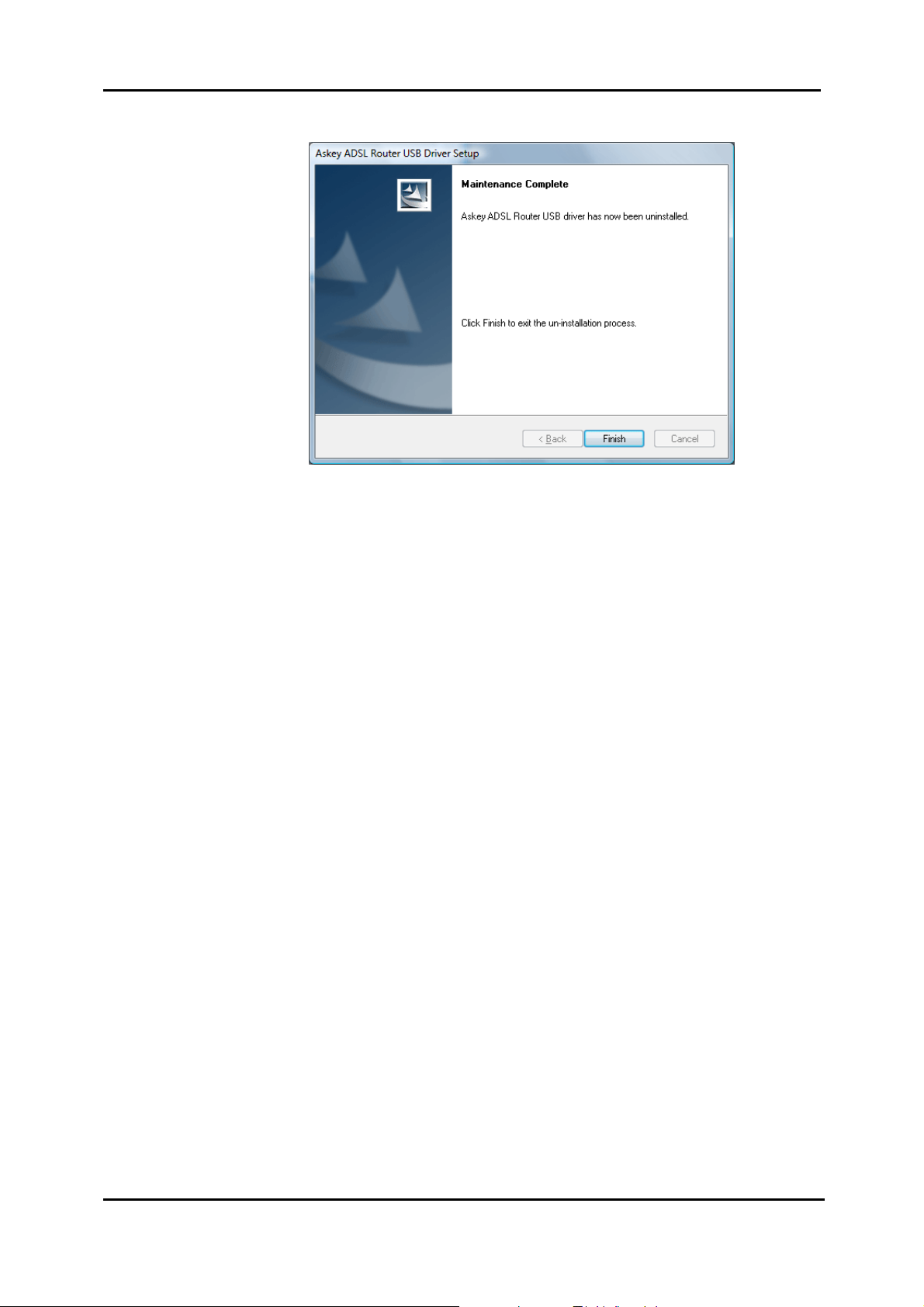
r When Maintenance Complete window shows up, click Finish to exit.
s The USB driver is successfully removed now.
28
Page 42
Chapter 2: System Requirement and Installation
Setting up TCP/IP
In order to access the Internet through the ADSL Router, each host on
your network must install/setup TCP/IP first. Please follow the steps
below to set your network adapter.
If the TCP/IP protocol has not been installed yet, please follow the steps below for
installation. In the following illustrations, we will set the PC to get an IP address
automatically at the same time.
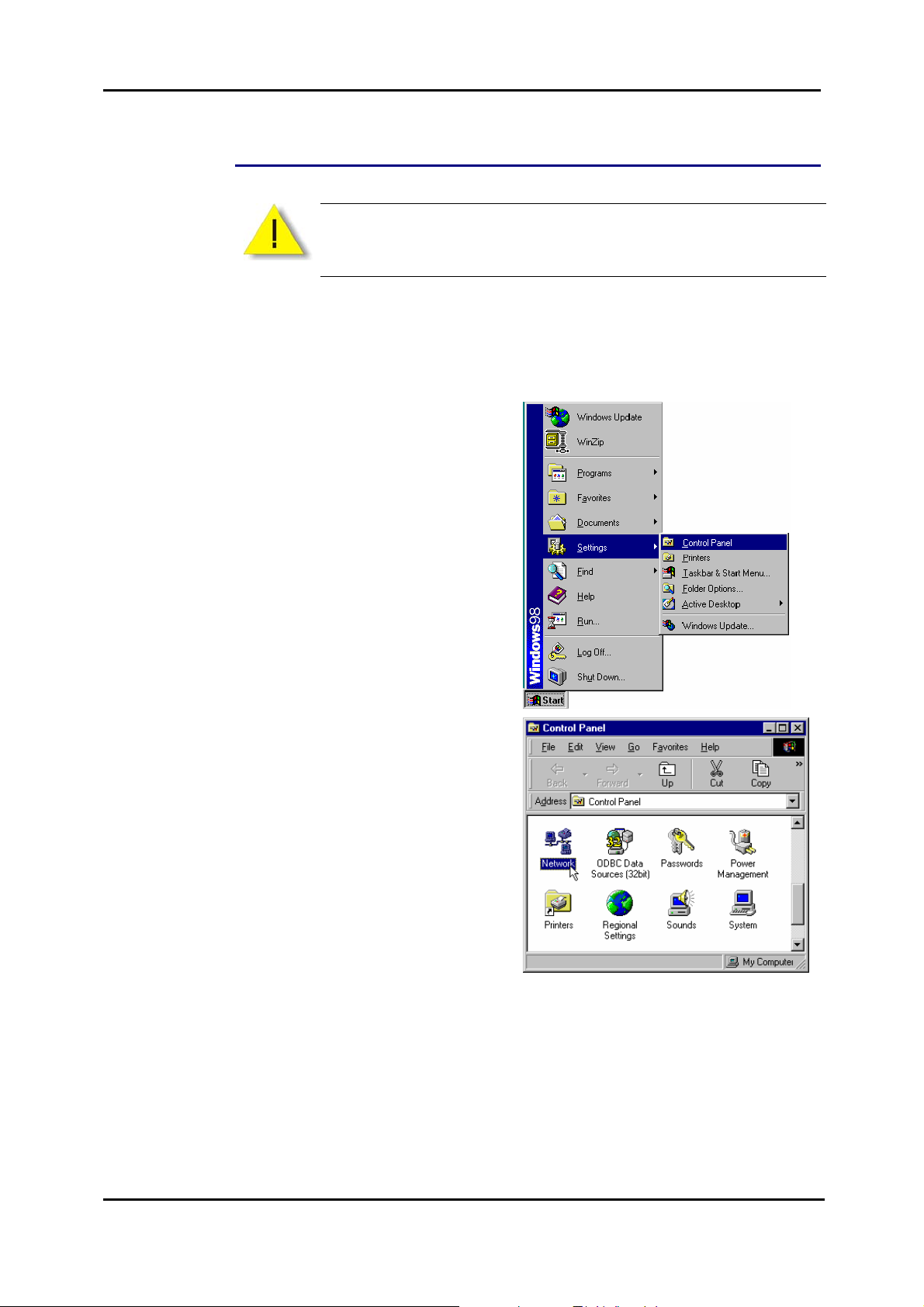
For Windows 98
1. Open the Start menu,
point to Settings and
click on Control Panel.
2. Double-click the Network icon.
29
Page 43
ADSL Router User Manual
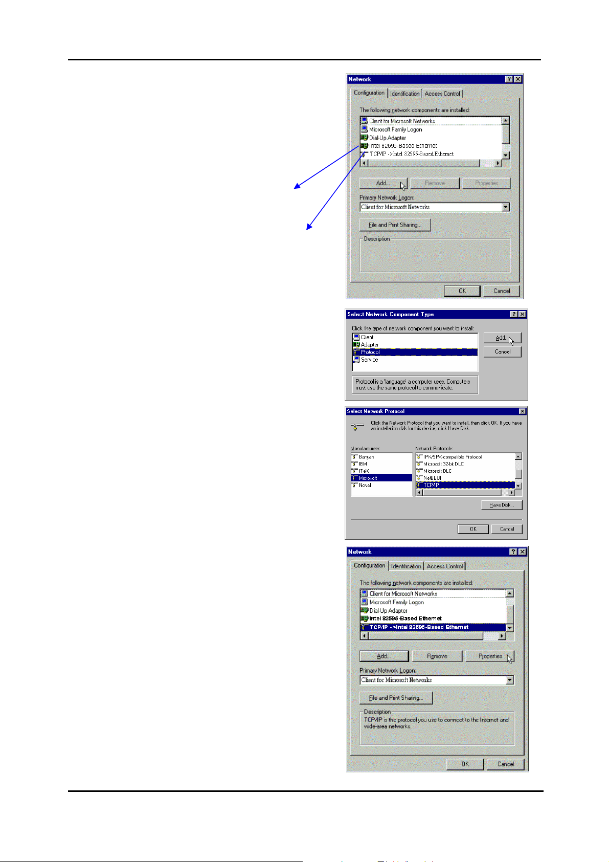
3. The Network window appears.
On the Configuration tab, check
out the list of installed network
components.
Option 1: If there is no TCP/IP
protocol, click Add.
Option 2: If you have TCP/IP
protocol, skip to Step 6.
Your network
interface card.
Check out if TCP/IP
for your NIC is
installed or not.
4. Highlight Protocol and click Add.
5. Highlight Microsoft on the left
side of the window, and select
TCP/IP on the right side. Then
click OK.
6. When returning to the Network
window, highl ight TCP/IP
protocol for your NIC and click
Properties.
30
Page 44

Chapter 2: System Requirement and Installation
7. On the IP Address tab:
Enable Obtain an IP address
automatically and click OK.
8. When returning to the Network
window, click OK
9. Wait for Windows when copying
files.
10. When prompted with System
Settings Change dialog box,
click Yes to restart your
computer.
31
Page 45

ADSL Router User Manual
For Windows ME
1. Open the Start menu, point to
Settings and click on Control
Panel.
2. Double-click the Network icon.
3. The Network window appears. On
the Configuration tab, check out
the list of installed network
components.
Option 1: If there is no TCP/IP
protocol, click Add.
Option 2: If you have TCP/IP
protocol, skip to Step 6.
Your network
interface card.
Check out if TCP/IP
for your NIC is
installed or not.
4. Highlight Protocol and click Add.
32
Page 46

Chapter 2: System Requirement and Installation
5. Highlight Microsoft on the left
side of the windows, and select
TCP/IP on the right side. Then
click OK.
6. While returning to Network
window, highlight TCP/IP protocol
for your NIC and click Properties.
7. On IP Address tab:
Enable Obtain an IP address
automatically and click OK.
33
Page 47

ADSL Router User Manual
8. While returning to the Network
window, click OK.
9. Wait for Windows when copying
files.
10. When prompted with the System
Settings Change dialog box, click
Yes to restart your computer.
For Windows NT
1. Click Start, point to Settings, and
then click Control Panel.
2. Double-click the Network icon.
34
Page 48
Chapter 2: System Requirement and Installation
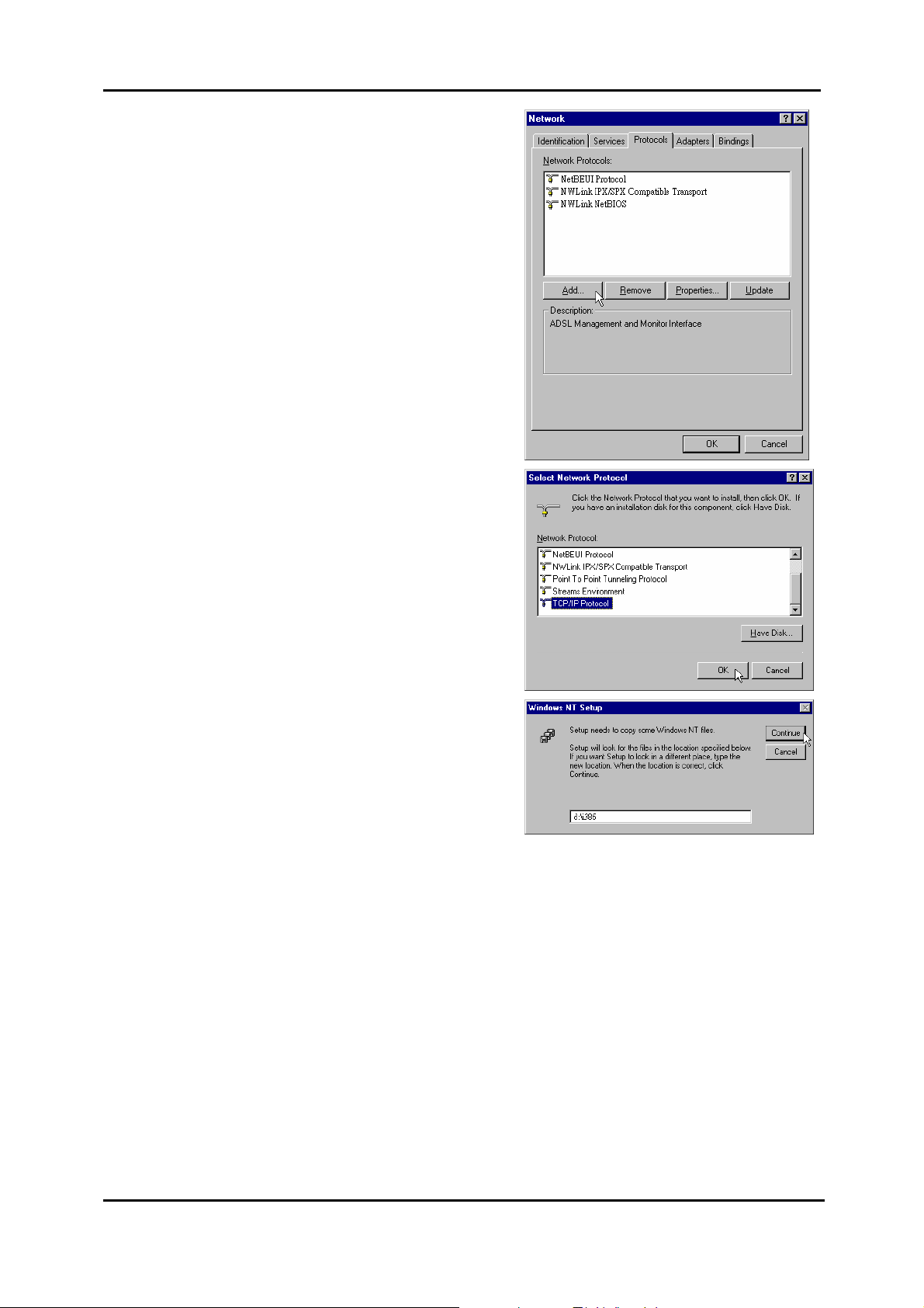
3. The Network window appears. On
the Protocols tab, check out the
list of installed network
components.
Option 1: If there is no TCP/IP
Protocol, click Add.
Option 2: If you have TCP/IP
Protocol installed, skip to Step 7.
4. Highlight TCP/IP Protocol and
click OK.
5. Insert the Windows NT CD into
your CD-ROM drive and type the
location of the CD. Then click
Continue.
35
Page 49

ADSL Router User Manual
6. When returning to the Network
window. Open the Protocols tab,
then select TCP/IP Protocol and
click Properties.
7. Enable Obtain an IP address
from a DHCP server and click
OK.
36
8. When prompted with the
message below, click Yes to
continue.
Page 50

Chapter 2: System Requirement and Installation
9. When returning to Network
window, click Close.
10. When prompted with Network
Settings Change dialog box,
click Yes to restart your
computer.
For Windows 2000
1. From the Start menu, point to
Settings and then click Network
and Dial-up Connections.
37
Page 51

ADSL Router User Manual
2. Right-click the Local Area
Connection icon and then click
Properties.
3. On the General tab, check out
the list of installed network
components.
Option 1: If there is no TCP/IP
Protocol, click Install.
Option 2: If you have TCP/IP
Protocol, skip to Step 6.
38
4. Highlight Protocol and then click
Add.
Page 52

Chapter 2: System Requirement and Installation
5. Click Internet Protocol (TCP/IP)
and then click OK.
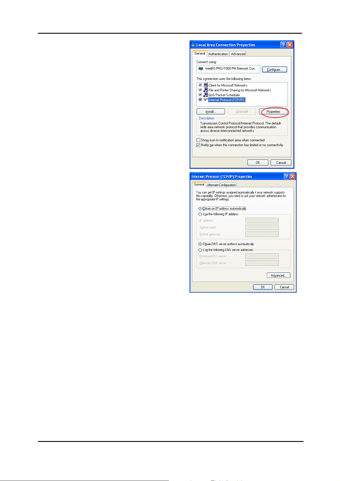
6. When returning to the Local
Area Connection Properties
window, highlight Internet
Protocol (TCP/IP) and then click
Properties.
7. Under the General tab, enable
Obtain an IP address
automatically. Then click OK.
39
Page 53

ADSL Router User Manual
For Windows XP
1. Open the Start menu, point to
Control Panel and click it.
2. Double click the Network
Connection.
3. Right click Local Area
Connection and then click
Properties.
40
Page 54

Chapter 2: System Requirement and Installation
4. On the General tab, check out
the list of installed network
components.
Option 1: If there is no TCP/IP
Protocol, click Install.
Option 2: If you have TCP/IP
Protocol, skip to Step 7.
If there is no TCP/IP
protocol installed on your
PC, press Install to continue.
5. Highlight Protocol and then
click Add.
6. Click Internet
Protocol(TCP/IP) and then
click OK.
41
Page 55
ADSL Router User Manual
7. When it returns to the General
Tab on the Local Area
Connection Properties
window, highlight Internet
Protocol (TCP/IP) and then
click Properties.
8. Under the General tab, select
Obtain an IP address
automatically, and Obtain
DNS server address
automatically. Then click Ok.
42
Page 56

Chapter 2: System Requirement and Installation
For Windows Vista
1. Open the Start menu,
point to Control Panel
and click it.
2. Click Network and
Internet.
3. Select Network and
Sharing Center.
43
Page 57

ADSL Router User Manual
4. Click Manage Network
Connection on the left
side.
5. Right click Local Area
Connection and select
Properties.
6. On the Networking tab,
you will find Internet
Protocol Version 6 and
Version 4. Contact your
ISP to confirm which one
will be used. (We take
TCP/IPv4 for example
here.)
Select Internet Protocol
Version 4 (TCP/IPv4)
and press Properties.
44
Page 58
Chapter 2: System Requirement and Installation
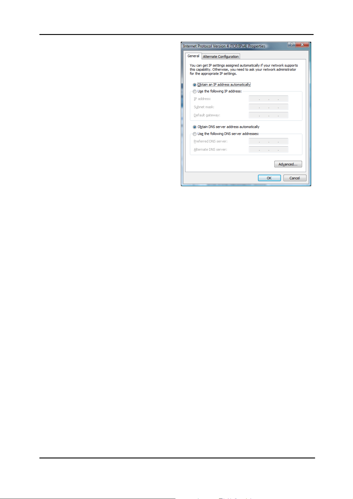
7. Under the General tab,
select Obtain an IP
address automatically,
and Obtain DNS server
address automatically.
Then click Ok to exit.
45
Page 59
ADSL Router User Manual
Renewing IP Address on Client PC
After the ADSL Router gets on line, there is a chance that your PC does n ot renew
its IP address and thus causes the PC not able to access the Internet. To solve this
problem, please follow the procedures below to renew PC’s IP address.
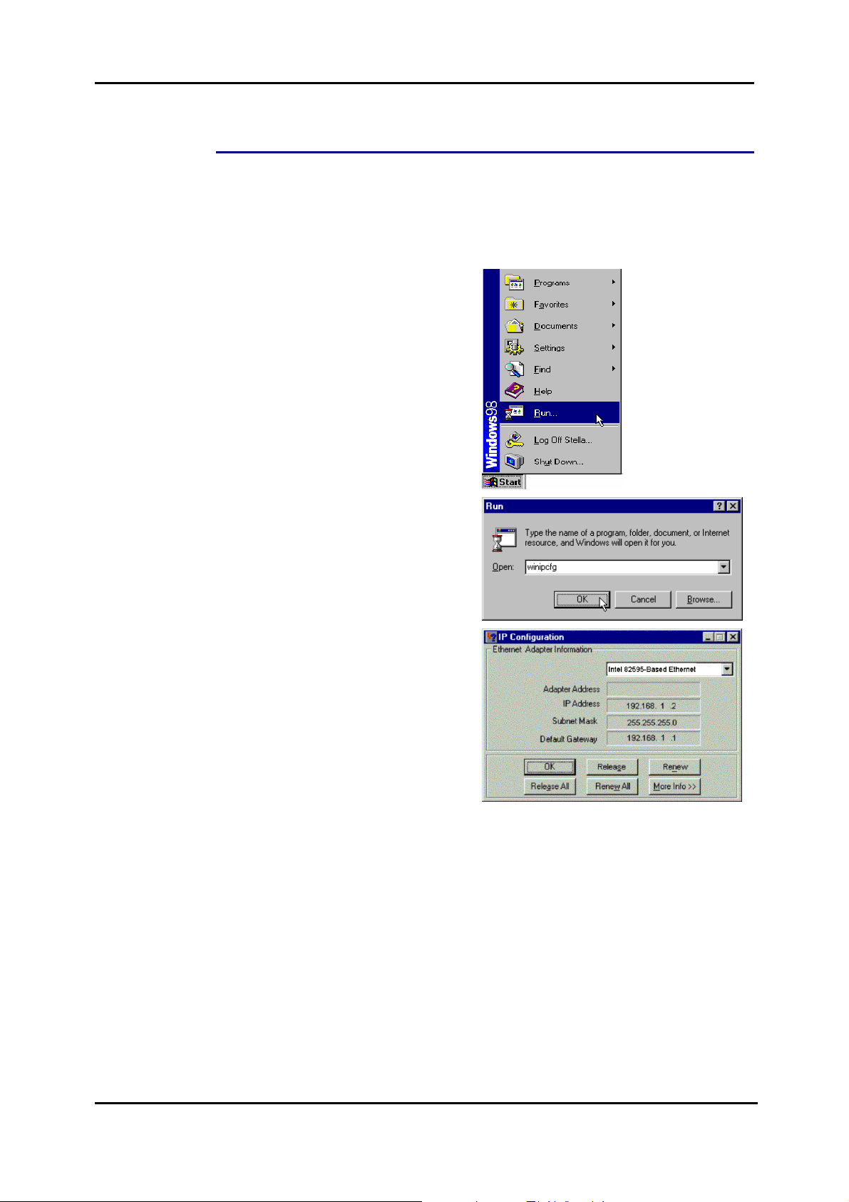
For Windows 98/ME
1. Select Run from the Start menu.
2. Type winipcfg in the text box and
click OK.
3. When the figure below appears,
click Release to let go of the
address and then click the Renew
button to obtain a new IP address.
46
Page 60

Chapter 2: System Requirement and Installation
For Windows NT/2000/XP
1. Open the Start menu, and click
Run... on this menu.
2. Type cmd in the text box that
appears and click OK. Then you
will see the command prompt
window.
Another way to open the
command prompt:
From Start menu, point to
Programs, select Accessories,
and then click Command Prompt.
3. Type ipconfig at the command
prompt window and press Enter to
view the computer’s IP information
from DHCP server.
47
Page 61
ADSL Router User Manual
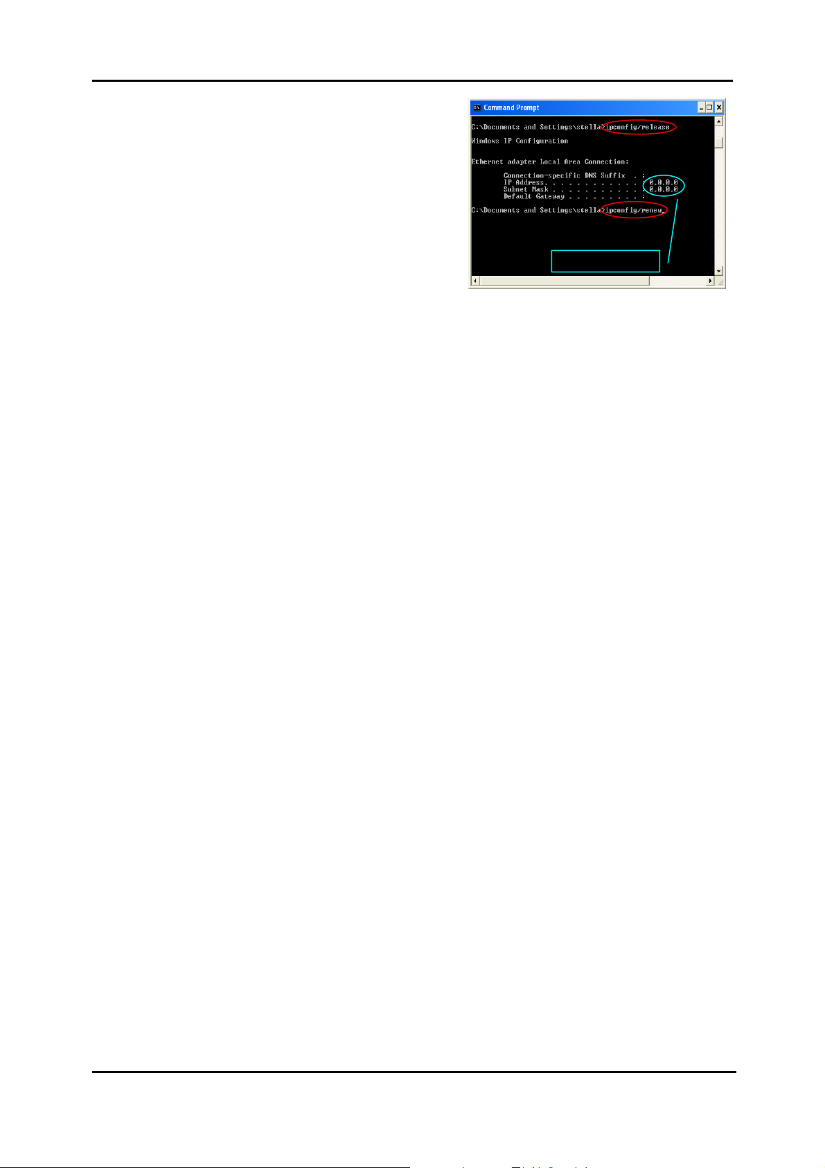
4. If the computer is holding a
current IP address, type ipconfig
/release to let go of the address,
then type ipconfig /renew to
obtain a new one.
Released IP Address
48
Page 62
Chapter 2: System Requirement and Installation
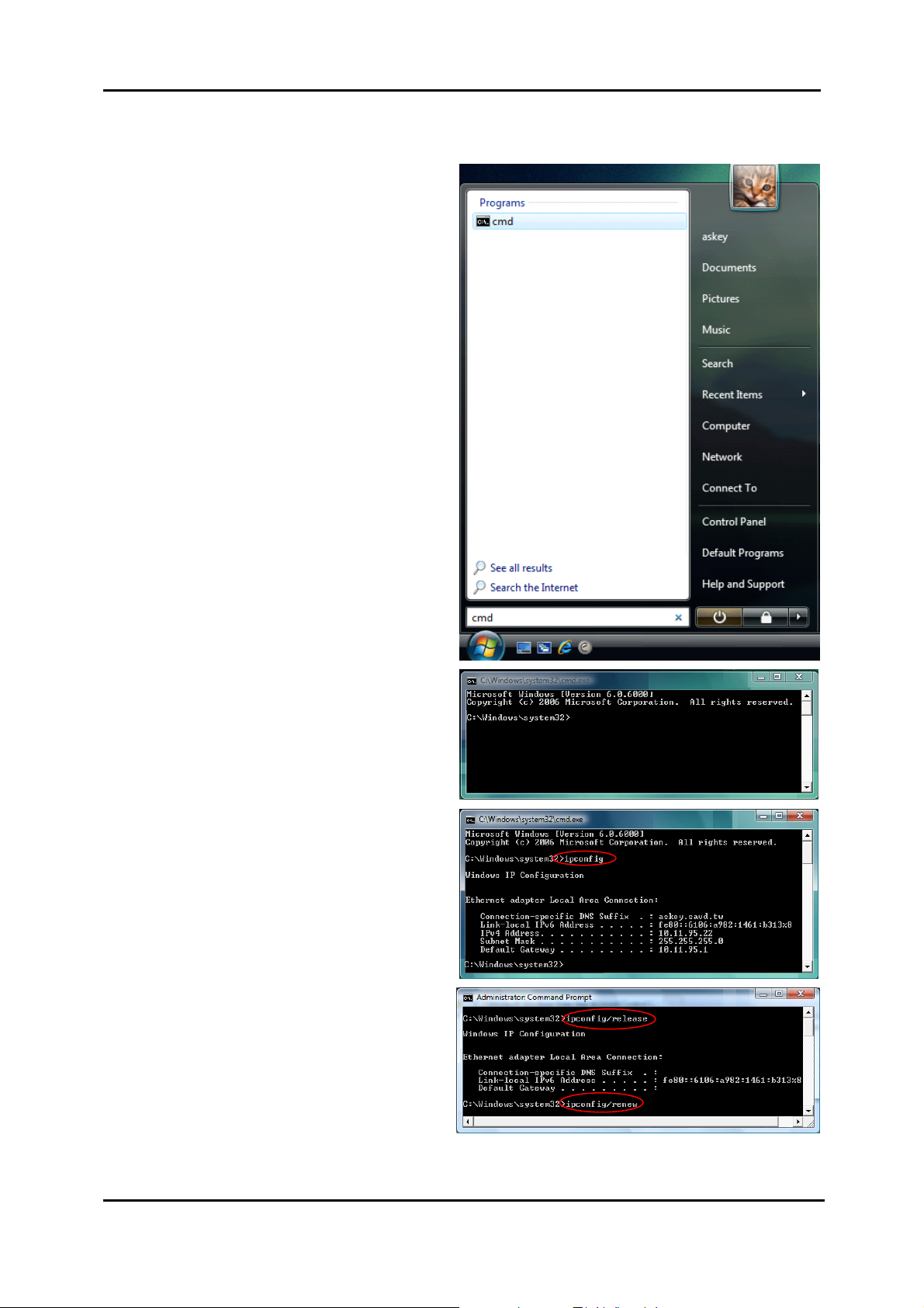
For Windows Vista
1. Open the Start menu, and
type cmd in the text box
then click OK.
2. The command prompt
window will appear.
3. Type ipconfig at the
command window and
press Enter to view the
computer’s IP information
from DHCP server.
4. If the computer is holding a
current IP address, type
ipconfig /release to let go
of the address, then type
ipconfig /renew to obtain
a new one.
49
Page 63
ADSL Router User Manual
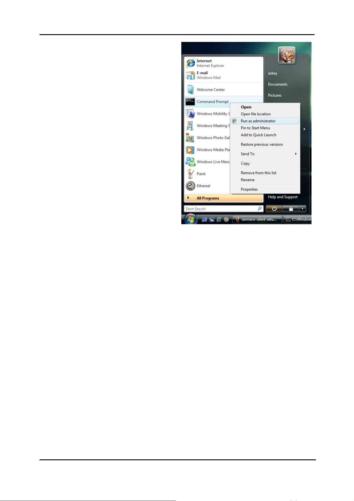
Note:
If you cannot release the IP
address successfully and see
the message “The requested
operation requires
elevation,” please go to the
Start menu and right click
Command Prompt, then set
Run as administrator.
Press Continue when a dialog
asking for permission to
continue prompts.
After then, repeat the above
instruction to release and
renew the IP address.
50
Page 64

Chapter 3: Accessing the Internet
Chapter 3: Accessing the Internet
This chapter aims to help you access the Internet in a quick and
convenient way. If you nee d more detailed information for web
configuration, please refer to the next chapter for the advanced
configuration.
Before configuring the ADSL Router, you must decide whether to configure the
ADSL Router as a bridge or as a router. This chapter presents some deployment
examples for your reference. Each mode includes its general configure procedures.
For more detailed information about web configuration, refer to "Web Configuration".
PPP over ATM (PPPoA)
PPPoA IP Extenstion
PPP over Ethernet (PPPoE)
PPPoE IP Extension
Numbered IP over ATM (IPoA)
Numbered IP over ATM (IPoA) + NAT
Unnumbered IP over ATM (IPoA)
Unnumbered IP over ATM (IPoA) + NAT
Bridge Mode
MER (Bridge Mode + NAT)
To ensure your PC accessing the Internet successfully, please check the following
first.
A netwo rk interface card is installed on your PC.
The ADS L Router is solidly connected with your computer.
The TCP/IP protocol has been installed and the IP address setting is to
obtain IP address automatically.
When all above preparations are ready, you can open the Browser and type
“192.168.1.1” into the URL box and start to make the web configuration for different
connection modes.
This chapter is going to introduce the function of each connection mode and the
basic configuring steps that you have to do. If you do not follow the configuring steps
for using these connection modes, you might get some connection pro blems and
cannot connect to the Internet well.
51
Page 65

ADSL Router User Manual
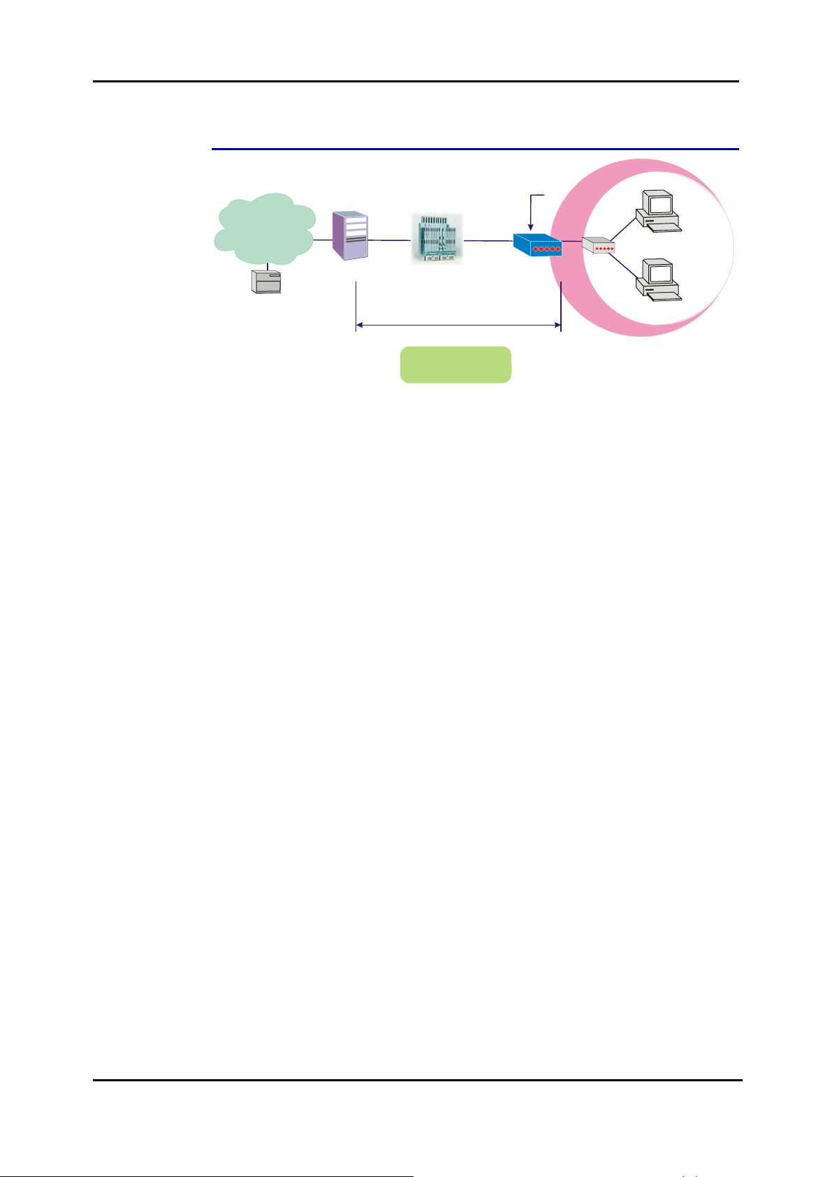
PPP over ATM (PPPoA) Mode
Default Private IP
192.168.1.1
Ethernet
Hub
192.168.1.2
PC(S)
192.168.1.3
ISP
(Internet Service Provider)
AAA
RDAIUS
Server
*BRAS: Broadband
Remote Access Server
BRAS
Dynamic Public IP
assigned by BRAS
STM-1
DSLAM
PPP over ATM
PPPoA+NAT+DHCP
on Private LAN
Loop
ADSL
Router
Description:
In this deployment environment, the PPPoA session is between the ADSL WAN
interface and BRAS. The ADSL Router gets a public IP address from BRAS when
connecting to DSLAM. The multiple client PCs will get private IP addre s s from the
DHCP server enabled on private LAN. The enabled NAT mechanism will translate
the IP information for clients to access the Internet.
Configuration:
1. Start your browser and type 192.168.1.1 as the address to access ADSL
web-based manager.
2. Go to Quick Start – Quick Setup. Uncheck Auto Scan Internet Connection
(PVC). Key in the VCI and VPI value, e.g.:
VPI – 0
VCI – 38
Click the Next button.
3. On the Configure Internet Connection – Connection Type page, select PPP
over A TM (PPPoA) then click the Next button.
4. On the WAN IP Settings page, select Obtain an IP address automatically
and check Enable NAT box. Click Next.
5. On the PPP Username and Password page, enter the PPP username and
password that you got from your ISP. Select Always on or select Dial on
Demand and key in the inactivity timeout value. (The default value is 20
minutes.) Then click Next.
6. On the Configure LAN side Settings page, key in the IP address and subnet
mask for your LAN, e.g.:
Primary IP address: 192.168.1.1
Subnet Mask: 255.255.255.0
Check DHCP Server on box. And key in the start and end IP address, e.g.:
Start IP Address:192.168.1.2
End IP Address: 192.168.1.254
Then enter the leased time ( the default is 1 day), and click Next.
7. Check the network information on This Internet Connection – Summary
page. Make sure the settings match the information provided by your ISP. Click
Finish.
52
Page 66
Chapter 3: Accessing the Internet
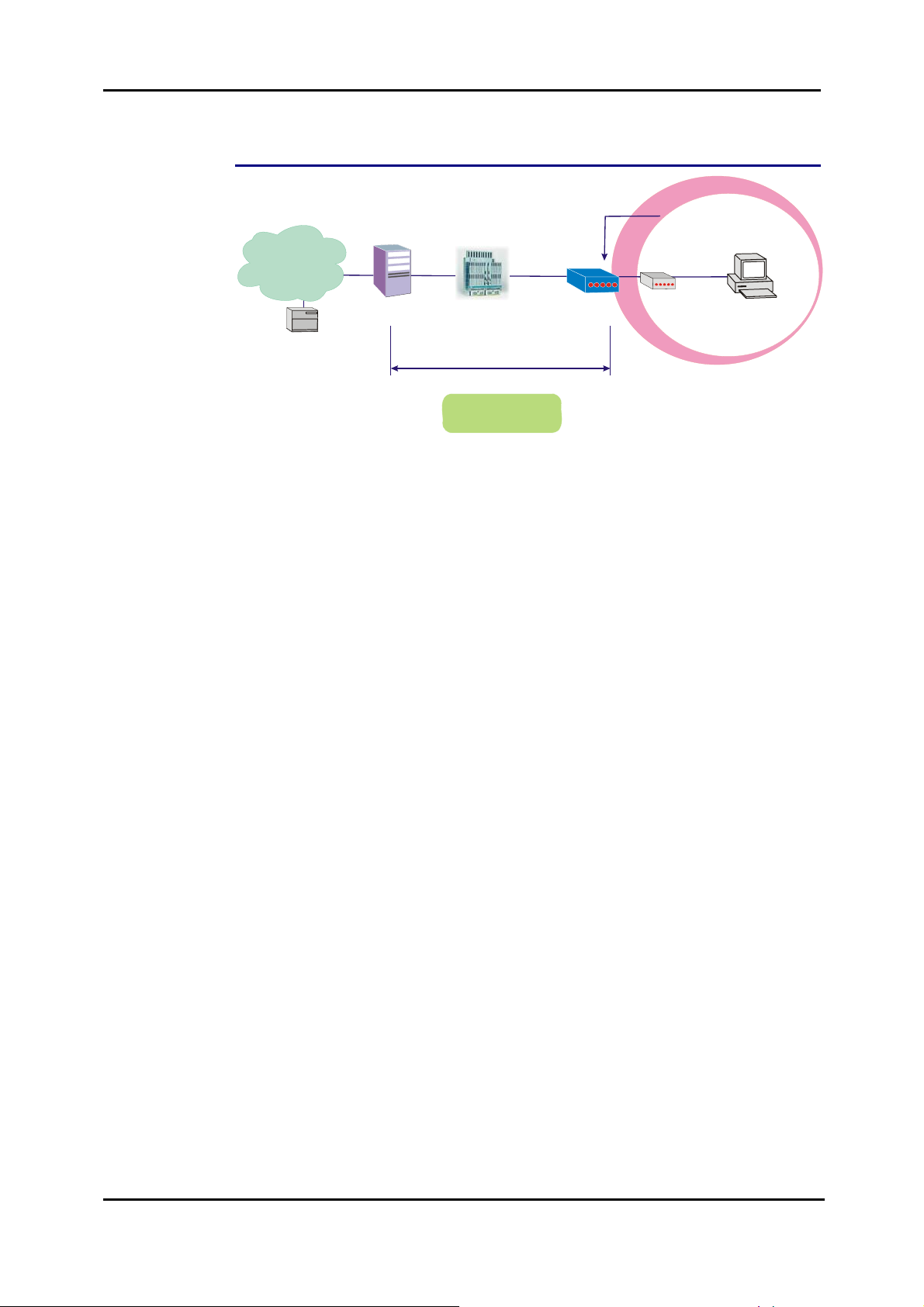
PPP over ATM (PPPoA) IP Extension Mode
ISP
(Internet Service Provider)
AAA
RDAIUS
Server
BRAS
STM-1
DSLAM
Loop
ADSL
Router
Hub
Default Private IP
192.168.1.1
Dynamic Public IP
assigned by BRAS
Ethernet
PC
*BRAS: Broadband
Remote Access Server
PPP over ATM
PPPoA+NAT+DHCP
on Private LAN
Description:
In this deployment environment, the PPPoA session is between the ADSL WAN
interface and BRAS. The ADSL Router acts as a bridge and receives a public IP
address from BRAS for your computer. And only the one that bears the public IP
address is allowed to access the Internet. Moreover, no NAT translation will be done
at this case.
Configuration:
1. Start your browser and type 192.168.1.1 in the URL box to access ADSL
web-based manager.
2. Go to Advanced – Internet – Connec tions. And click Add.
3. Key in the VCI and VPI value, e.g.:
VPI – 0
VCI – 38
Click the Next button.
4. On the Configure Internet Connection – Connection Type page, select PPP
over A TM (PPPoA) then click the Next button.
5. On the WAN IP Settings page, select Obtain an IP address automatically,
check PPP IP extension (and Enable NAT would become disabled
automatically) then click Next.
6. On the PPP Username and Password page, enter the PPP username and
password offered by your ISP. Select Always on, and then click Next.
7. Check the network information on This Internet Connection – Summary
page. Make sure the settings match the settings provided by the ISP. Click
Apply.
8. Press Finish.
53
Page 67
ADSL Router User Manual
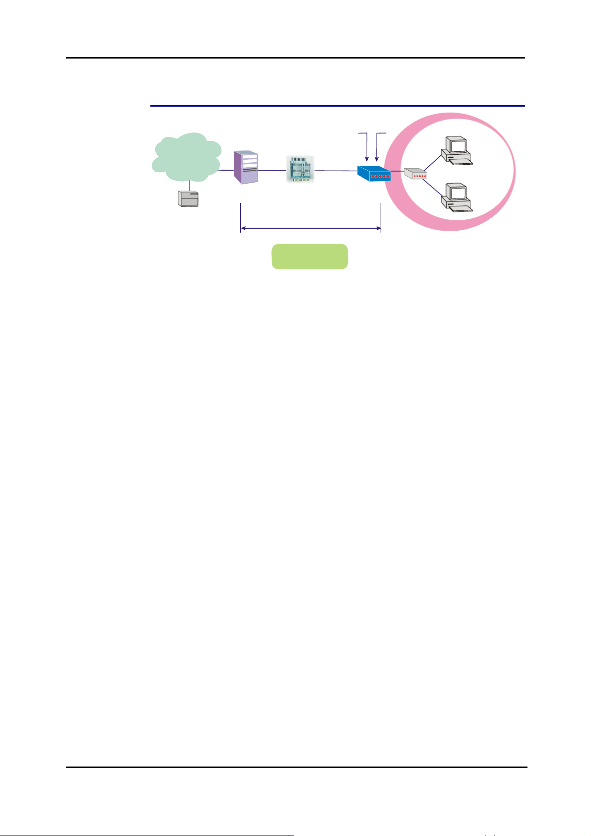
PPP over Ethernet (PPPoE) Mode
Default Private IP
192.168.1.1
ADSL
Router
192.168.1.3
Ethernet
Hub
192.168.1.2
PC(S)
ISP
(Internet Service Provider)
AAA
RDAIUS
Server
*BRAS: Broadband
Remote Access Server
BRAS
Dynamic Public IP
assigned by BRAS
STM-1
DSLAM
Loop
PPP over Ethernet
PPPoE+NAT+DHCP
on Private LAN
Description:
In this deployment environment, the PPPoE session is between the ADSL WAN
interface and BRAS. The ADSL Router gets a public IP address from BRAS when
connecting to DSLAM. The multiple client PCs will get private IP addre s s from the
DHCP server enabled on private LAN. The enabled NAT mechanism will translate
the IP information for clients to access the Internet.
Configuration:
1. Start your browser and type 192.168.1.1 in the URL box to access ADSL
web-based manager.
2. Go to Quick Start – Quick Setup. Uncheck Auto Scan Internet Connection
(PVC). Key in the VCI and VPI value, e.g.:
VPI – 0
VCI – 39
Click the Next button.
3. On the Configure Internet Connection – Connection Type page, select PPP
over Ethernet (PPPoE) then click the Next button.
4. On the WAN IP Settings page, select Obtain an IP address automatically
and check Enable NAT box. Click Next.
5. On the PPP Username and Password page, enter the PPP username and
password that you got from your ISP. Select Always on or select Dial on
Demand and key in the inactivity timeout value. (The default value is 20
minutes.) Then click Next.
6. On the Configure LAN side Settings page, key in the IP address and subnet
mask for your LAN, e.g.:
Primary IP address: 192.168.1.1
Subnet Mask: 255.255.255.0
Check DHCP Server on box. And key in the start and end IP address, e.g.:
Start IP Address:192.168.1.2
End IP Address: 192.168.1.254
Then enter the leased time ( the default is 1 day), and click Next.
7. Check the network information on This Internet Connection -- Summary
page. Make sure the settings match the information provided by your ISP. Click
Finish.
54
Page 68

Chapter 3: Accessing the Internet
PPP over Ethernet (PPPoE) IP Extension Mode
Default Private IP
192.168.1.1
ISP
(Internet Service Provider)
STM-1
Loop
Ethernet
Dynamic Public IP
assigned by BRAS
Hub
PC(S)
AAA
RDAIUS
Server
*BRAS: Broadband
Remote Access Server
BRAS
DSLAM
ADSL
Router
PPP over Ethernet
PPPoE IP
Extension Mode
Description:
In this deployment environment, the PPPoE session is between the ADSL WAN
interface and BRAS. The ADSL Router acts as a bridge and gets a public IP address
from BRAS for your computer. And only the one that got the public IP address is
allowed to access into Internet. The real IP that you got is acquired from ISP.
Moreover, no NAT translation will be done at this case.
Configuration:
1. Start your browser and type 192.168.1.1 in the URL box to access ADSL
web-based manager.
2. Go to Advanced – Internet – Connec tions. And click Add.
3. Key in the VCI and VPI value, e.g.:
VPI – 0
VCI – 39
Click the Next button.
4. On the Configure Internet Connection – Connection Type page, select PPP
over Ethernet (PPPoE) then click the Next button.
5. On the WAN IP Settings page, select Obtain an IP address automatically,
check PPP IP extension (and Enable NAT would become disabled
automatically) then click Next.
6. On the PPP Username and Password page, enter the PPP username and
password offered by your ISP. Select Always on, and then click Next.
7. Check the network information on This Internet Connection -- Summary
page. Make sure the settings match the settings provided by the ISP. Click
Apply.
8. Press Finish.
55
Page 69

ADSL Router User Manual
r
(
)
Numbered IP over ATM (IPoA)
ISP
Internet Service Provider
RDAIUS
Server
*BRAS: Broadband
Remote Access Serve
AAA
BRAS
STM-1
DSLAM
IP over ATM
Public IP Pre-assigned
by ISP
Default Private IP
192.168.1.1
Loop
10.11.95.233
10.11.80.81
ADSL
Router
10.11.80.82
10.11.80.83
S/W
Hub
PC(S)
Description:
If you apply for multiple IP addresses from your ISP, you can assign these public IP
addresses to the ADSL Router and public server, e.g., Web or FTP server. Typically
the first IP is network address, the second is used as router IP address and the last
one is for subnet broadcasting. Other remaining IP addre s ses can be assigned to
PCs on the LAN.
The following example uses the LAN IP address ranging from 10.11.80.81 to
10.11.80.86 and the subnet mask for LAN is 255.255.255.248. The WAN IP address
is 10.11.95.233, and the subnet mask for WAN is 255.255.255.248.
Configuration:
1. Start your browser and type 192.168.1.1 in the URL box to access ADSL
web-based manager.
2. Go to Quick Start – Quick Setup. Uncheck Auto Scan Internet Connection
(PVC). Key in the VCI and VPI value, e.g.:
VPI – 0
VCI – 32
Click the Next button.
3. On the Configure Internet Connection – Connection Type page, select IP
over A TM (IPoA) then click Next.
4. On the WAN IP Settings page, select Use the following IP address and Use
the following DNS Server Address, then key in the information that your ISP
offered, e.g.:
WAN IP Address: 10.11.95.233
WAN Subnet Mask: 2 55.255.255.248
Primary DNS server: 168.95.1.1
Secondary DNS server: 168.95.192.1
Uncheck Enable NAT and click Next.
5. On the Configure LAN side Settings page, key in the information for your
LAN, e.g.,
Primary IP Address: 192.168.1.1
Subnet mask: 255.255.255.0
Start IP Address: 192.168.1.2
End IP Address: 192.168.1.254
6. Check Configure the second IP Address and Subnet Mask for LAN
Interface and enter the information needed.
Secondary IP Address: 10.11.80.81
56
Page 70

Chapter 3: Accessing the Internet
Subnet mask: 255.255.255.248
Click Next.
7. Check the network information on the Summary page. Make sure the settings
match the settings provided by your ISP. Click Finish.
8. Refer to the TCP/IP properties, specify an IP Address, and fill in other
information needed, e.g.:
IP Address: 10.11.80.82
Subnet Mask: 255.255.255.248
Gateway: 10.11.80.81
Preferred DNS server: 168.95.1.1
9. Now the router is well-configured. You can access the Internet.
57
Page 71

ADSL Router User Manual
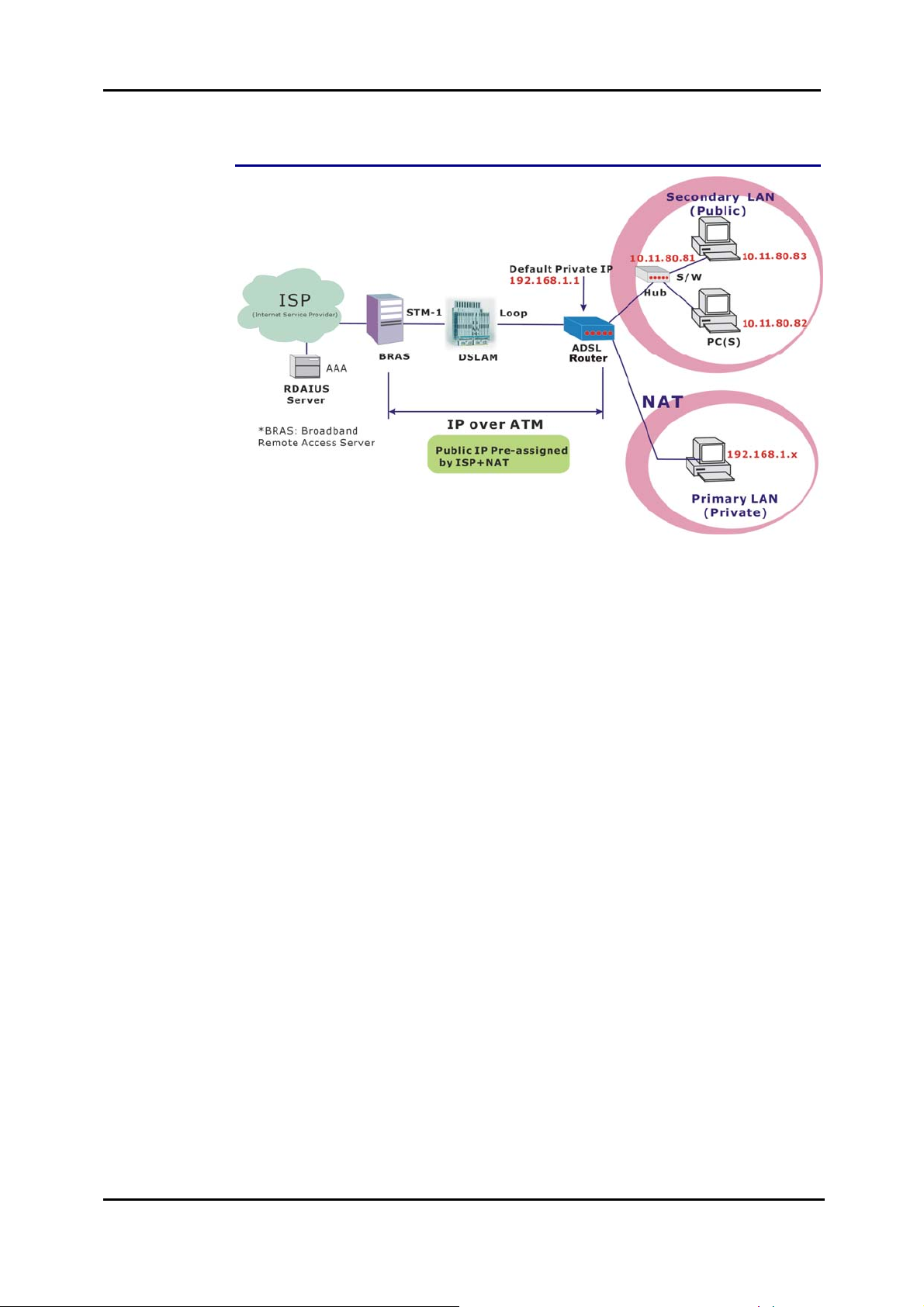
Numbered IP over ATM (IPoA)+NAT
Description:
In this deployment environment, we make up a private IP network of 192.168.1.1.
NAT function is enabled (on ADSL Router or use another NAT box connected to hub)
to support multiple clients to access the Router and some public servers (WWW,
FTP).
If you apply for multiple IP addresses from your ISP, you can assign these public IP
addresses to the ADSL Router and public server, e.g., Web or FTP server. Typically
the first IP is network address, the second is used as router IP address and the last
one is subnet broadcasting. Other remaining IP addresses can be assigned to PCs
on the LAN.
The following example uses the IP address ranging from 10.11.80.81 to 10.11.80.86
and the subnet mask is 255.255.255.248.
Configuration:
1. Start your browser and type 192.168.1.1 in the URL box to access ADSL
web-based manager.
2. Go to Quick Start – Quick Setup. Uncheck Auto Scan Internet Connection
(PVC). Key in the VCI and VPI value, e.g.:
VPI – 0
VCI – 32
Click the Next button.
3. On the Configure Internet Connection – Connection Type page, select IP
over A TM (IPoA) then click Next.
58
4. On the WAN IP Settings page, select Use the following IP address and Use
the following DNS Server Address, then key in the information that your ISP
offered, e.g.:
WAN IP Address: 10.11.80.81
WAN Subnet Mask: 2 55.255.255.248
Primary DNS server: 168.95.1.1
Secondary DNS server: 168.95.192.1
5. Check the Enable NAT bo x. And click Next.
Page 72

Chapter 3: Accessing the Internet
6. On the Configure LAN side Settings page, key in the information for your
LAN, e.g.,
Primary IP Address: 192.168.1.1
Subnet mask: 255.255.255.0
Start IP Address: 192.168.1.2
End IP Address: 192.168.1.254
7. Check the network information. Make sure the settings match the settings
provided by ISP. Click Finish.
8. Now the router is well configured. You can access into Internet.
59
Page 73

ADSL Router User Manual
r
(
)
Unnumbered IP over ATM (IPoA)
ISP
Internet Service Provider
RDAIUS
Server
*BRAS: Broadband
Remote Access Serve
AAA
BRAS
STM-1
DSLAM
IP over ATM
Public IP Pre-assigned
by ISP
Default Private IP
192.168.1.1
Loop
10.11.80.81
ADSL
Router
10.11.80.83
S/W
Hub
10.11.80.82
PC(S)
Description:
If you apply for multiple IP addresses from your ISP, you can assign these public IP
addresses to the ADSL Router and public server, e.g., Web or FTP server. Typically
the first IP is network address, the second is used as router IP address and the last
one is subnet broadcasting. Other remaining IP addresses can be assigned to PCs
on the LAN.
The following example uses the IP address ranging from 10.11.80.81 to 10.11.80.86
and the subnet mask is 255.255.255.248. In such circumstance, we do not assign
any WAN IP.
Configuration:
1. Start your browser and type 192.168.1.1 in the URL box to access ADSL
web-based manager.
2. Go to Quick Start – Quick Setup. Uncheck Auto Scan Internet Connection
(PVC). Key in the VCI and VPI value, e.g.:
VPI – 0
VCI – 32
Click the Next button.
3. On the Configure Internet Connection – Connection Type page, select IP
over A TM (IPoA) then click Next.
4. On the WAN IP Settings page, select None for WAN IP address settings.
Then, select Use the following DNS Server Address and key in the
information that your ISP offered, e.g.:
Primary DNS server: 168.95.1.1
Secondary DNS server: 168.95.192.1
Uncheck Enable NAT and click Next.
5. On the Configure LAN side Settings page, key in the information for your
LAN, e.g.,
Primary IP Address: 192.168.1.1
Subnet mask: 255.255.255.0
Start IP Address: 192.168.1.2
End IP Address: 192.168.1.254
6. Check Configure the second IP Address and Subnet Mask for LAN
Interface and enter the information needed, e.g.,
Secondary IP Address: 10.11.80.81
Subnet mask: 255.255.255.248
Check DHCP Server Off a nd click Next
.
60
Page 74

Chapter 3: Accessing the Internet
7. Check the network information on the Summary page. Make sure the settings
match the settings provided by your ISP. Click Finish.
8. Refer to the TCP/IP properties, specify an IP Address, and fill in other
information needed, e.g.:
IP Address: 10.11.80.82
Subnet Mask: 255.255.255.248
Gateway: 10.11.80.81
Preferred DNS server: 168.95.1.1
9. Now the router is well-configured. You can access the Internet.
61
Page 75
ADSL Router User Manual
Unnumbered IP over ATM (IPoA)+NAT
Description:
If you apply for multiple IP addresses from your ISP, you can assign these public IP
addresses to the ADSL Router and public server, e.g., Web or FTP server. Typically
the first IP is network address, the second is used as router IP address and the last
one is subnet broadcasting. Other remaining IP addresses can be assigned to PCs
on the LAN.
The following example uses the IP address ranging from 10.11.80.81 to 10.11.80.86
and the subnet mask is 255.255.255.248. In such circumstance, we enable NAT
function but not assign any WAN IP.
Configuration:
1. Start your browser and type 192.168.1.1 in the URL box to access ADSL
web-based manager.
2. Go to Quick Start – Quick Setup. Uncheck Auto Scan Internet Connection
(PVC). Key in the VCI and VPI value, e.g.:
VPI – 0
VCI – 32
Click the Next button.
3. On the Configure Internet Connection – Connection Type page, select IP
over A TM (IPoA) then click Next.
4. On the WAN IP Settings page, select None for WAN IP address settings.
Then, select Use the following DNS Server Address and key in the
information that your ISP offered, e.g.:
Primary DNS server: 168.95.1.1
Secondary DNS server: 168.95.192.1
62
5. Check the Enable NAT bo x. And click Next.
6. On the Configure LAN side Settings page, key in the information for your
LAN, e.g.,
Primary IP Address: 192.168.1.1
Subnet mask: 255.255.255.0
Start IP Address: 192.168.1.2
End IP Address: 192.168.1.254
Page 76

Chapter 3: Accessing the Internet
7. Check Configure the second IP Address and Subnet Mask for LAN
Interface and enter the information needed, e.g.,
Secondary IP Address: 10.11.80.81
Subnet mask: 255.255.255.248
Click Next.
8. Check the network information on the Summary page. Make sure the contents
match the settings provided by your ISP. Click Finish.
9. Now the router is well-configured. You can access the Internet.
63
Page 77
ADSL Router User Manual
r
(
)
Bridge Mode
Default Private IP
192.168.1.1
ISP
Internet Service Provider
AAA
RDAIUS
Server
*BRAS: Broadband
Remote Access Serve
BRAS
STM-1
DSLAM
Bridge Mode
Loop
ADSL
Router
Hub
PPPoE
Client S/W
PC(S)
Description:
In this example, the ADSL Router acts as a bridge which bridging the PC IP
addresses from LAN to WAN. The PC IP address can be a static public address that
is pre-assigned by the ISP or a dynamic public address that is assigned by the ISP
DHCP server, or an IP address received from PPPoE software.
Therefore, it does not require a public IP address. It only has a default private IP
address (192.168.1.1) for management purpose.
Configuration:
1. Choose a client PC and set the IP as 192.168.1.x (x is between 2 and 254) and
the gateway as 192.168.1.1.
2. Start your browser and type 192.168.1.1 in the URL box to access ADSL
web-based manager.
3. Go to Quick Start – Quick Setup. Uncheck Auto Scan Internet Connection
(PVC). Key in the VCI and VPI value, e.g.,
VPI – 0
VCI – 35
Then click the Next button.
4. On the Configure Internet Connection – Connection Type page, select
Bridging then click the Next button.
5. On the WAN IP Settings page, select None for WAN IP address settings.
6. On the Configure LAN side Settings page, enter the IP address and subnet
mask for your LAN, e.g.:
Primary IP address: 192.168.1.1
Subnet Mask: 255.255.255.0
Choose DHCP Server Off and click Next.
7. Check the network information on the Summary page. Make sure the contents
match the settings provided by your ISP. Click Finish.
8. Refer to the TCP/IP properties, specify an IP Address, and fill in other
information needed, e.g.:
IP Address: 10.11.86.81
Subnet Mask: 255.255.255.248
Gateway: 10.11.86.1
Preferred DNS server: 168.95.1.1
9. Click OK. Now the router is well-configured. You can access to the Internet.
64
Page 78
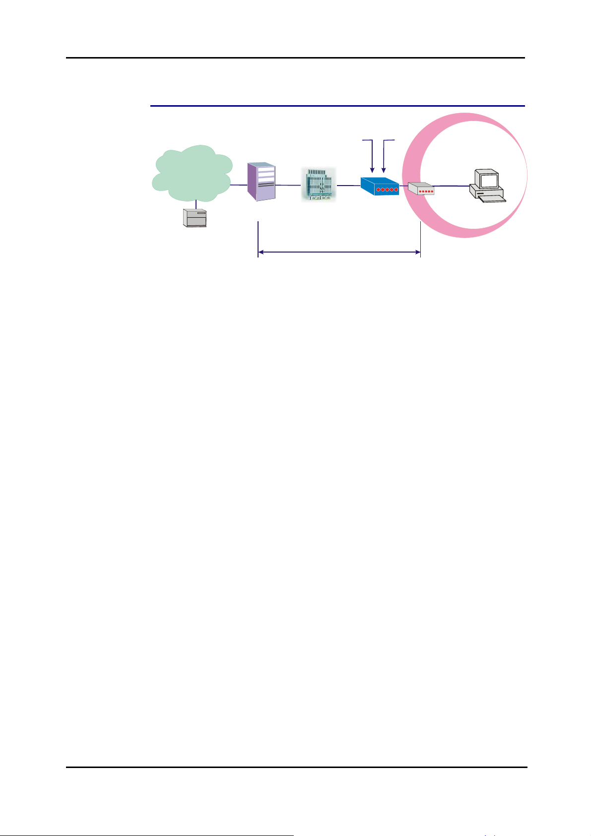
MER
R
r
(
)
Chapter 3: Accessing the Internet
Default Private IP
192.168.1.1
ADSL
Router
Ethernet
Hub
PC
ISP
Internet Service Provider
RDAIUS
Server
*BRAS: Broadband
Remote Access Serve
AAA
BRAS
Public IP
assigned by BRAS
STM-1
DSLAM
ME
Loop
Description:
In this deployment environment, we make up a private IP network of 192.168.1.1.
NAT function is enabled to support multiple clients to access to Internet.
In this example, the ADSL Router acts as a NAT device which translates a private IP
address into a public address. Therefore multiple users can sh are with one public IP
address to access the Internet through this router. The public address can be a
static public address that is pre-assigned by ISP or a dynamic public address that is
assigned by the ISP DHCP server.
Configuration:
1. Start your browser and type 192.168.1.1 in the URL box to access ADSL
web-based manager.
2. Go to Quick Start – Quick Setup. Unchec k Auto Scan Internet Connection
(PVC). Key in the VCI and VPI value, e.g.,
VPI – 0
VCI – 37
Then click the Next button.
3. On the Configure Internet Connection – Connection Type page, select
Bridging and then click the Next button.
4. On the WAN IP Settings page, select Obtain an IP address automatically;
then, select Obtain DNS server address automatically.
5. Check Enable NA T. Then click Next.
6. On the Configure LAN side Settings page, key in the IP address and subnet
mask for your LAN. Check DHCP Server On box, and enter the start and end
points, e.g.:
Primary IP address:192.168.1.1
Subnet Mask:255.255.255.0
Start IP Address:192.168.1.2
End IP Address: 192.168.1.254
Then key in the leased time that you want. And click Next
7. Check the network information on the Summary page. Make sure the contents
match the settings provided by your ISP. Click Finish.
8. Now the router is well-configured. You can access the Internet.
65
Page 79

ADSL Router User Manual
66
Page 80

Chapter 4: Web Configuration
Chapter 4: Web Configuration
Some users might want to set specific configuration for the router
such as firewall, data transmission rate…, and so on. This chapter
will provide you advanced information of the web pages for the router
for your reference.
Using Web-Based Manager
After properly configuring you host PC, please proceed as follows:
1. Start your web browser and type
192.168.1.1, the private IP address of the
ADSL Router, in the URL field.
2. After connecting to the device, you will be
prompted to enter username and
password. By default, both the username
and the password are admin. An example
under Windows XP is shown as the left
figure.
If you login successfully, the main page will
appear. From now on, the ADSL Router
acts as a web server sending HTML
pages/forms on your request. You can fill
in these pages/forms and apply them to
the ADSL Router.
67
Page 81
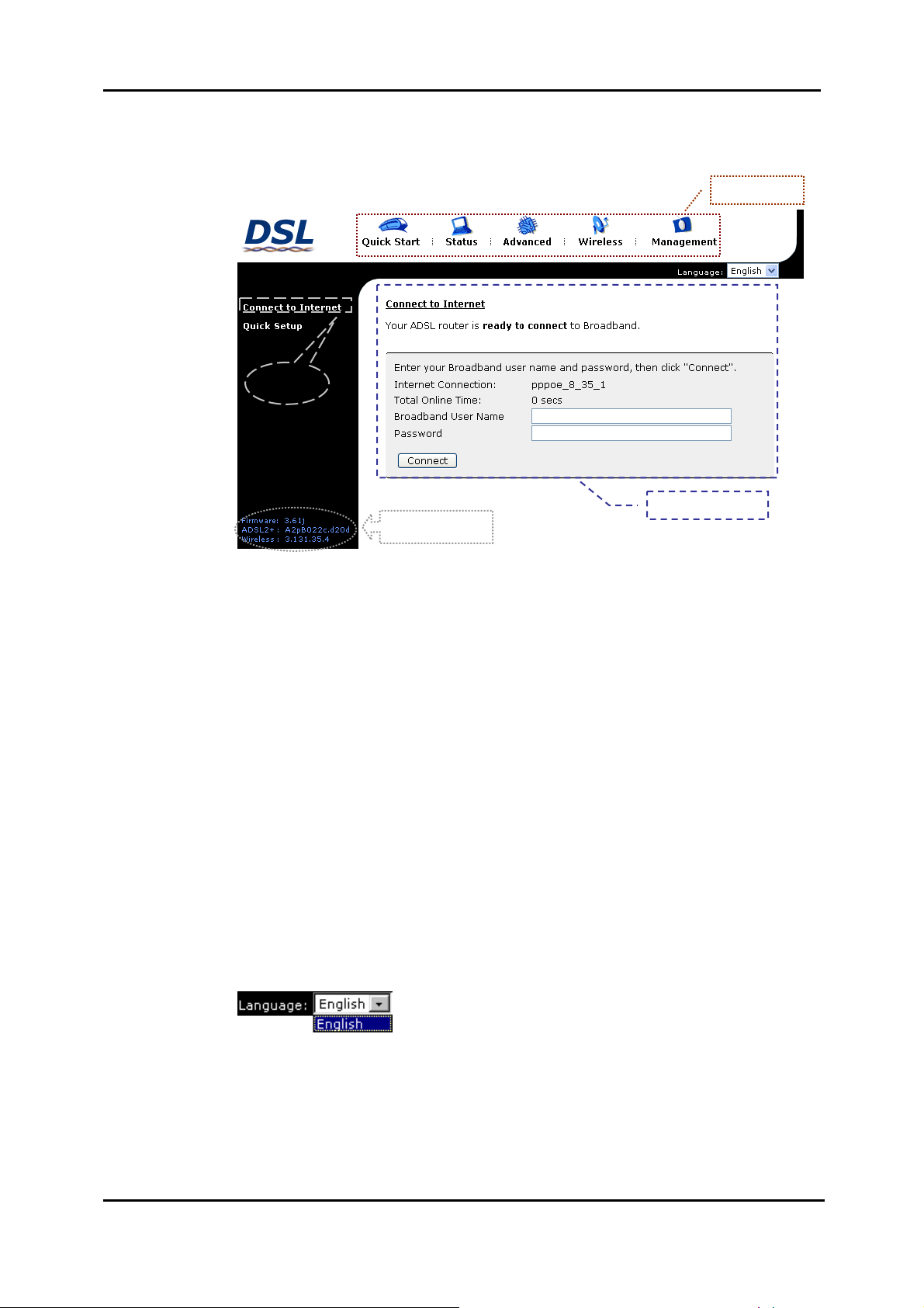
ADSL Router User Manual
Outline of Web Manager
To configure the web page, please use admin as the username and the password.
The main screen will be shown as below.
Title
Main Menu
Main Window
Current Version
Title: The title of this management interface.
Main
Menu:
Main
Window:
Current
Version:
Including Quick Start, Status, Advanced, Wireless, and Management.
The current workspace of the web manager, containing configuration
or status information.
Here provides the version info for firmware, ADSL2+, and Wireless.
To Have the New Settings Take Effect
After selecting or adjusting the settings according to your needs, your
customizations will be saved to the flash memory before you restart the router. And
only after rebooting the router, your customizations may take effect.
Language
On the top to the right of this web page, it provides a drop-down menu for you to
choose a proper language. (However, we only offer English at present.)
68
Page 82

Chapter 4: Web Configuration
Quick Start
The pages under the Quick Start menu provide user a quick way to set up the router.
If you do not know much about the router , you can use the Quick Start pages to
adjust basic settings to activate your router.
Connect to Internet
This is a quick way to connect to the
Internet by using PPPoE interface,
please click Connect to Internet to
open the web page.
Enter the user name and password
(that you get from the ISP) for your
ADSL router and click Connect.
The system will connect automatically,
and then you can access the Internet.
Quick Setup
The quick setup wizard will guide you
to configure the ADSL router through
some specific steps. Yet different
connection interface will lead to
different setting pages. Refer to the
following pages for detailed
information.
Auto Scan Internet Connection
(PVC):
If there is no any PVC configured in
your ADSL router, you can check this
item. Otherwise, please uncheck this
box.
VPI (Virtual Path Identifier): Identifies
the virtual path between endpoint s in
an ATM network. The valid range is
from 0 to 255. To enter the setting,
please refer to the setting that the ISP
offered.
VCI (Virtual Channel Identifier):
Identifies the virtual channel endpoints
in an ATM network. The valid range is
from 32 to 65535 (1 to 31 is reserved
for well-known protocols). To enter the
setting, please refer to the setting that
the ISP gave you.
After entering the VPI/VCI value,
please click Next for the following
step.
69
Page 83

ADSL Router User Manual
Connection Type
The system provides several protocols for you to choose. Your ISP will offer you the
most suitable settings of the protocol. Before you set this page, please refer to the
protocol that your ISP offered.
After clicking on the Next button from
the VPI/VCI web page, the following
screen will appear. Please choose the
connection type and encapsulation
mode that you want to use and click
Next for next page.
For instance, PPP over Ethernet
(PPPoE) is selected in this
demonstrative figure.
PPP over ATM/ PPP over Ethernet
If the connection type you choose is PPP over ATM or PPP over Ethernet, please
refer to the following information.
According to the ISP’s configuration
on the server, you can choose PPPoE
or PPPoA modes.
Choose PPPoA or PPPoE and click
Next.
On this screen, you have to make the
settings for WAN IP. To get the IP
address automatically, click the
Obtain an IP address automatically
radio button. Or click Use the
following IP address button and
enter the IP address for WA N
interface.
Check Enable NAT if you need.
MTU:
It means the maximum size of the
packet that transmitted in the network.
The packet of the data greater than
the value set here will be divided into
several packets for transmitting.
Type the value into the field of MTU.
The default MTU value for PPPoE is
1492; while for PPPoA is 1500.
70
Click Next for the next procedure.
Page 84

PPP Username & PPP Password:
Key in the username and password
that you received from your ISP. (e.g.,
askey4/askey4)
Always On:
Select this item to make the
connection active all the time.
Dial on Demand:
Select this item to make a connection
automatically while in demand. Enter
the timeout to cut off the network
connection if there is no activity for
this router.
Manually Connect:
Select this item to make a connection
by pressing the Connect
the Advanced Setup-
Internet-Connections web page.
On the Configure LAN side Settings
page, you have to fill in the data
requested.
hyperlink on
Chapter 4: Web Configuration
Primary IP Address & Subnet Mask:
Key in the information that offered by
your ISP for the LAN connection.
Configure the secondary IP
Address and Subnet Mask:
Check this box to set up a secondary
IP Address to connect to your router if
they are not included in the range that
DHCP server accepts. See the next
figure for the secondary IP address
and subnet mask.
Secondary IP Address & Subnet
Mask:
Key in the second IP address and the
subnet mask received from the ISP for
your LAN connection.
MTU: (refer to the WAN section)
The default MTU value for LAN side
Settings is 1500. You may modify it if
necessary.
DHCP Server On:
Check this item if DHCP service is
needed on the LAN side. The router
will assign IP address and gateway
address for each of your PCs.
On this web page, the primary IP
address and subnet mask will be
shown on it. You can modify them
if needed.
Start IP Address & End IP Address:
Enter the information needed.
Lease Time:
Key in the duration for the time. The
default is 1day.
DHCP Server Off:
Check this item if DHCP service is not
needed on the LAN.
Key in all the necessary settings
and click Next for the coming
page.
71
Page 85

ADSL Router User Manual
You can check the contents on the
Summary page.
If you find anything incorrect, click
Back to modify the settings.
If everything is OK, click Finish to
accept these settings.
Now, the system will reboot to activate
the new settings that you have set in
this section.
Please wait for 2 minutes before
restarting the router.
72
Page 86

Chapter 4: Web Configuration
IP over ATM
If the type you have to choose is IP over ATM, please refer to the following
information.
IPoA is an alternative of LAN
emulation. It allows TCP/IP network to
access ATM network and uses ATM
quality of service’s features.
Choose IPoA and click Next.
None:
If it is not necessary to set the WAN IP
address, please click this button.
Obtain an IP address automatically:
Click this button to allow the system to
get an IP address automatically.
WAN IP Address & WAN Subnet
Mask:
If you choose Use the following IP
address, you have to enter the IP
address and subnet mask information
received from the ISP for the WAN
interface.
Obtain DNS server address
automatically:
Only when you select Obtain an IP
address automatically that this
option is available. You may click this
button to allow the system to get DNS
server address automatically.
After setting up the WAN IP and
DNS server information, click Next
to open the following page.
Use the following DNS server
addresses:
Select this item to set the DNS server
addresses manually, type the
information provided by your ISP in
the following Primary DNS and
Secondary DNS server entries, e.g.
168.95.1.1 and 168.95.192.1.
Click Enable NA T if you want.
On the Configure LAN side Settings
page, you have to fill in the data
requested.
Primary IP Address & Subnet Mask:
Key in the information that offered by
your ISP for the LAN connection, e.g.,
192.168.1.1 for IP address and
255.255.255.0 for subnet mask.
MTU:
(Please refer to the PPPoA/ PPPoE
section.) The default MTU setting here
is 1500. You may modify it if
necessary.
73
Page 87

ADSL Router User Manual
Configure the secondary IP
Address and Subnet Mask for LAN
interface:
Check this box to set up a secondary
IP Address to connect to your router if
they are not included in the range that
DHCP server accepts. You have to
key in the information received from
your ISP for the LAN connection, e.g.,
the secondary IP is 10.11.80.81 and
the mask is 255.255.255.248 in the
example illustrated in the figure.
DHCP Server On:
Check this item if DHCP service is
needed on the LAN side. The router
will assign IP address and gateway
address for each of your PCs.
Start IP Address & End IP Address:
Enter the information needed.
Lease Time:
Key in the duration for the time. The
default is 1day.
Key in all the necessary settings.
Click Next for the coming page.
DHCP Server Off:
Check this item if DHCP service is not
needed on the LAN.
You can check the settings on the
Summary page.
If you find anything incorrect, click
Back to modify the settings.
If everything is OK, click Finish to
accept these settings.
And the following page will appear.
Now, the system will reboot to activate
the new settings that you have set in
this section.
Please wait for 2 minutes before
restarting the router.
74
Page 88

Chapter 4: Web Configuration
Bridging
If the mode you choose is Bridging (or MER), please refer to the following
information.
The bridging mode can configure your
router to send and receive packets
between LAN and WAN interfaces.
The WAN interface is ATM PVC; the
LAN interface can be Ethernet, USB,
or Wireless.
Choose Bridging and click Next.
None:
If it is not necessary to set the WAN IP
address, please click this button. In
our example, we select this item.
Obtain an IP address automatically:
Click this button to allow the system to
get an IP address automatically.
WAN IP Address, WAN Subnet
Mask, and Default Gateway:
When choosing Use the following IP
address, you have to key in the IP
address, the subnet mask, and the
default gateway provided by your ISP
for the WAN interface.
While you choose to obtain the IP
address automatically or use specific
IP address, you have to decide
whether to select Obtain DNS server
address automatically or Use the
following DNS server address and
enter the information provided by you
ISP.
Check Enable NAT if necessary.
Press Next to continue.
Primary IP Address & Subnet Mask:
Key in the IP address and the subnet
mask that provided by your ISP for
LAN interface, e.g., 192.168.1.1 and
255.255.255.0, respectively.
MTU: Please refer to PPPoA/ PPPoE.
The default setting is none, while
selecting Obtain an IP address
automatically or Use the following
IP address, the DNS setting appears,
shown as the figure below.
DHCP Server On:
Check this item if DHCP service is
needed on the LAN. The router will
assign IP address and gateway
address for each of your PCs. Enter
the information for Start IP, End IP
and Lease Time if you enable this
function. The default value for lease
time is one day.
DHCP Server Off:
Check this item if DHCP service is not
needed on the LAN; like our example.
75
Page 89

ADSL Router User Manual
You can check the settings on the
Summary page now.
If you find anything incorrect, click
Back to modify the settings.
If everything is OK, click Finish to
accept these settings.
And the following page will appear.
Now, the system will reboot to activate
the new settings that you have done in
this section.
Please wait for 2 minutes before
restarting the router.
76
Page 90
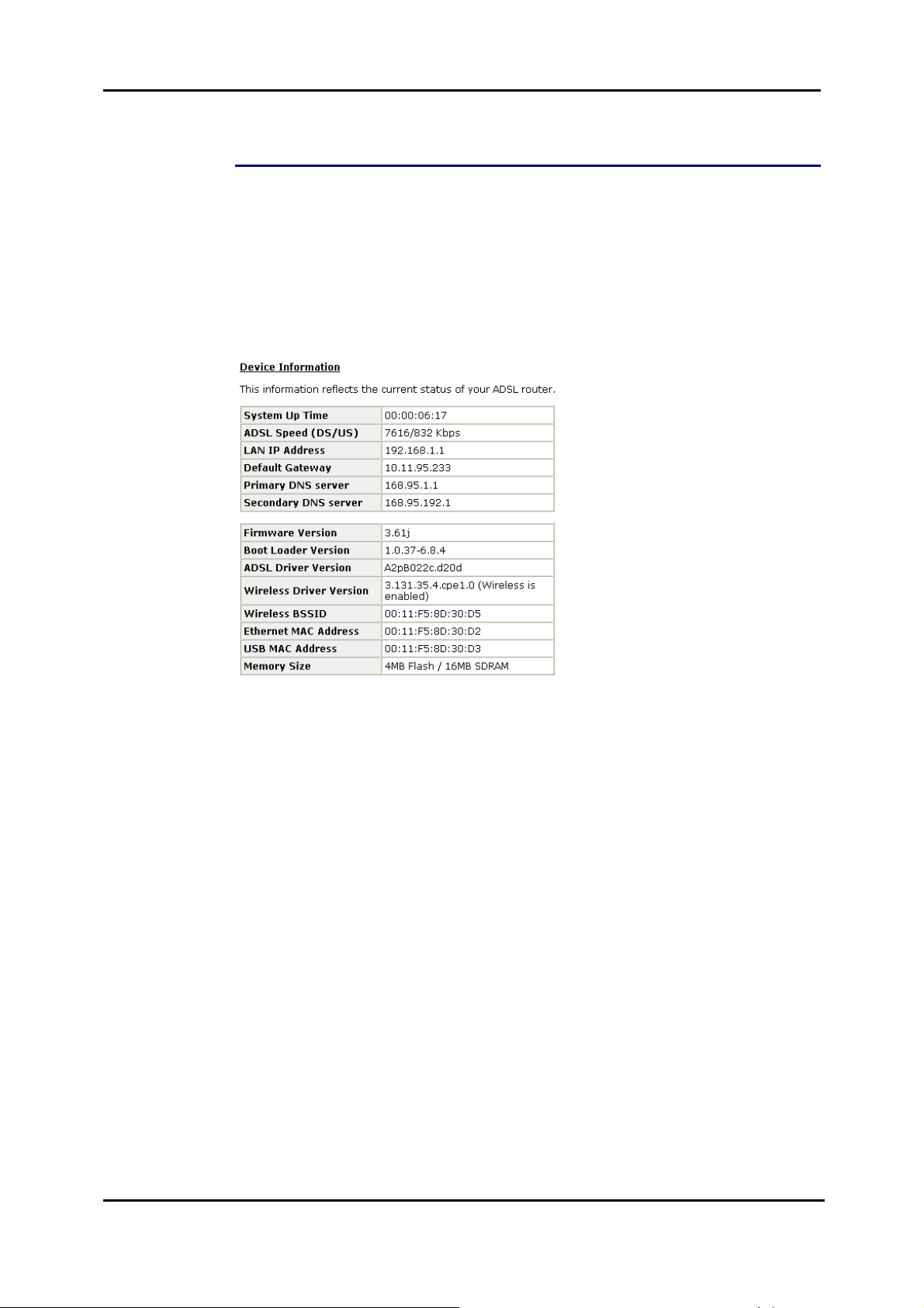
Chapter 4: Web Configuration
Status
Overview
This page displays the current status for the ADSL connection, including the period
of activating the router, ADSL speed, and the information about LAN IP address,
default gateway, DNS server, firmware version, boot loader version, wireless driver
version, wireless BSSID, and Ethernet MAC address. The system status will be
different according to the settings that you configured in the web pages.
77
Page 91
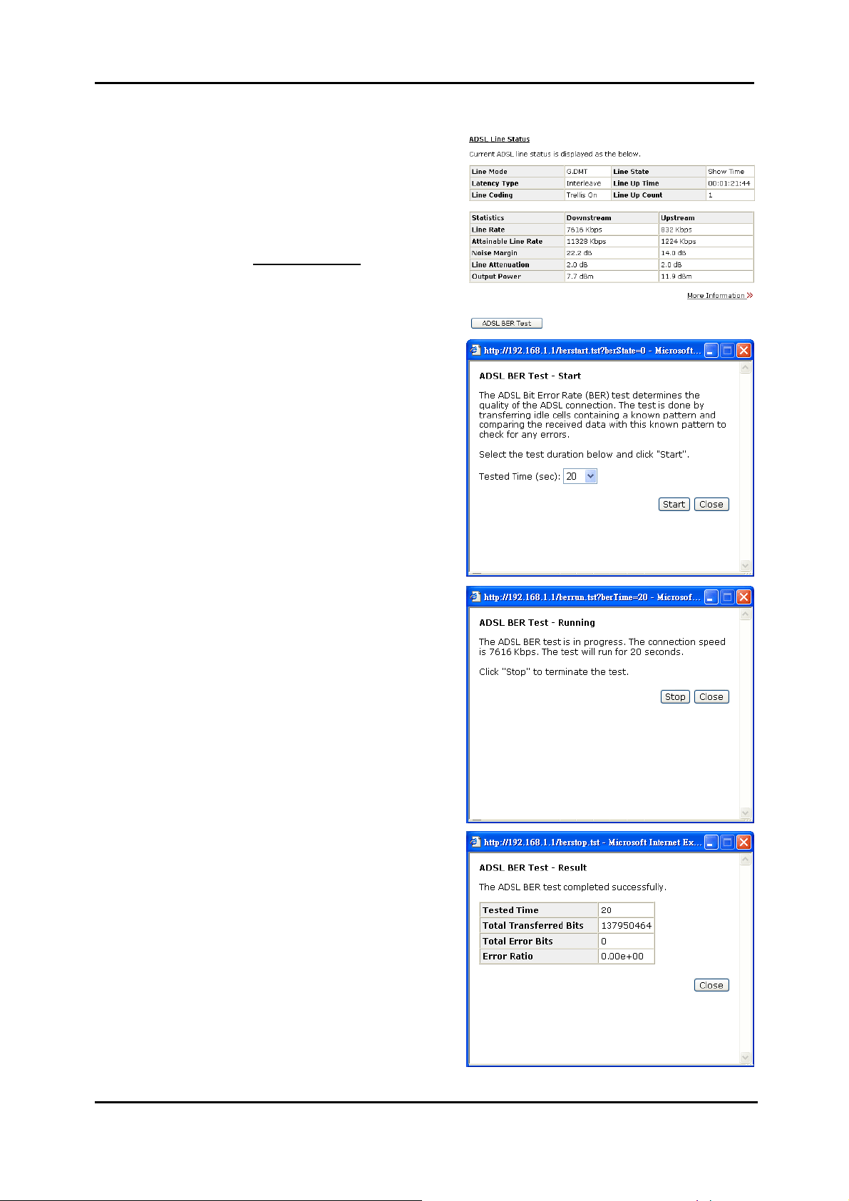
ADSL Router User Manual
ADSL Line
This page shows all information for
ADSL.
For knowing the quality of the ADSL
connection, please click ADSL BER
Test button to have advanced
information.
Click More Information
see more detailed information about
ADSL Line Status.
ADSL BER Test
This test determines the quality of the
ADSL connection. It is done by
transferring idle cells containing a
known pattern and comparing the
received data with this known pattern
to check for errors.
After selecting the test duration time
and click Start, the following dialog
appears to tell you the test is running.
You can stop the test by clicking Stop
or close this dialog window by
pressing Close.
hyperlink to
78
When the test is over, the result will be
shown on the following dialog window
for your reference. Click Close to
close this window.
Page 92

Internet Connection
This page displays the connection
information for your router, su ch as the
PVC name, VPI/VCI value, service
category, protocol, invoking NAT and
QoS or not, IP address, linking status,
and so on.
Traffic Statistics
This table shows the records of data
going through the LAN and WAN
interface. For each interface,
cumulative totals are displayed for
Received and Transmitted.
You may click Reset to reset the
amount.
DHCP Table
This table shows all DHCP clients who
get their IP addresses from your ADSL
Router. For each DHCP client, it
shows the Host Name, MAC
Address, IP Address and the Lease
Time.
Chapter 4: Web Configuration
Wireless Clients
This table shows the MAC address for
all of the wireless LAN clients currently
associated to your ADSL Router.
Routing Table
This table shows the routing rules that
your router uses.
ARP Table
This table shows the IP address
record for IP-to-Physical translation in
your router.
79
Page 93
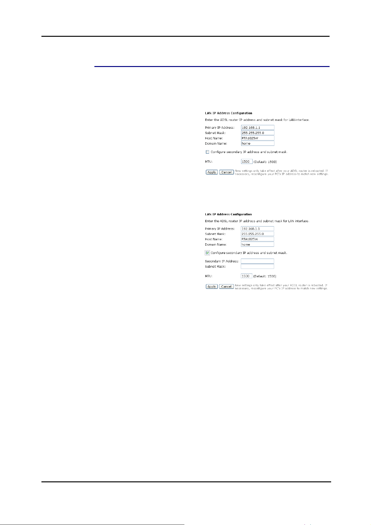
ADSL Router User Manual
Advanced Setup
Local Network – IP Address
This page is the same as you can see on the Configure LAN side Settings page
while running the Quick Setup. It allows you to set IP Address and Subnet Mask
values for LAN interface.
Primary IP Address:
Key in the first IP address that you
received from your ISP for the LAN
connection.
Subnet Mask:
Key in the subnet mask that you
received from your ISP for the LAN
connection.
Host Name:
List the host name of this device.
Domain Name:
List the name of the domain.
Configure the secondary IP
Address and Subnet Mask:
Check this box to enter another set of
IP Address and Subnet Mask to
connect to your router if they are not
included in the range that DHCP
server accepts.
After checking this box, the secondary
IP address and subnet mask entries
will show up, as shown in the right
figure.
Secondary IP Address & Subnet
Mask: Enter the information provided
by your ISP for your LAN connection.
MTU:
It means the maximum size of the
packet that transmitted in the network.
The packet of the data greater than
the number set here will be divided
into several packets for transmitting.
Type the value into the field of MTU.
The default setting for LAN
configuration is 1500.
80
Apply:
Click this button to activate the
settings listed above.
Page 94
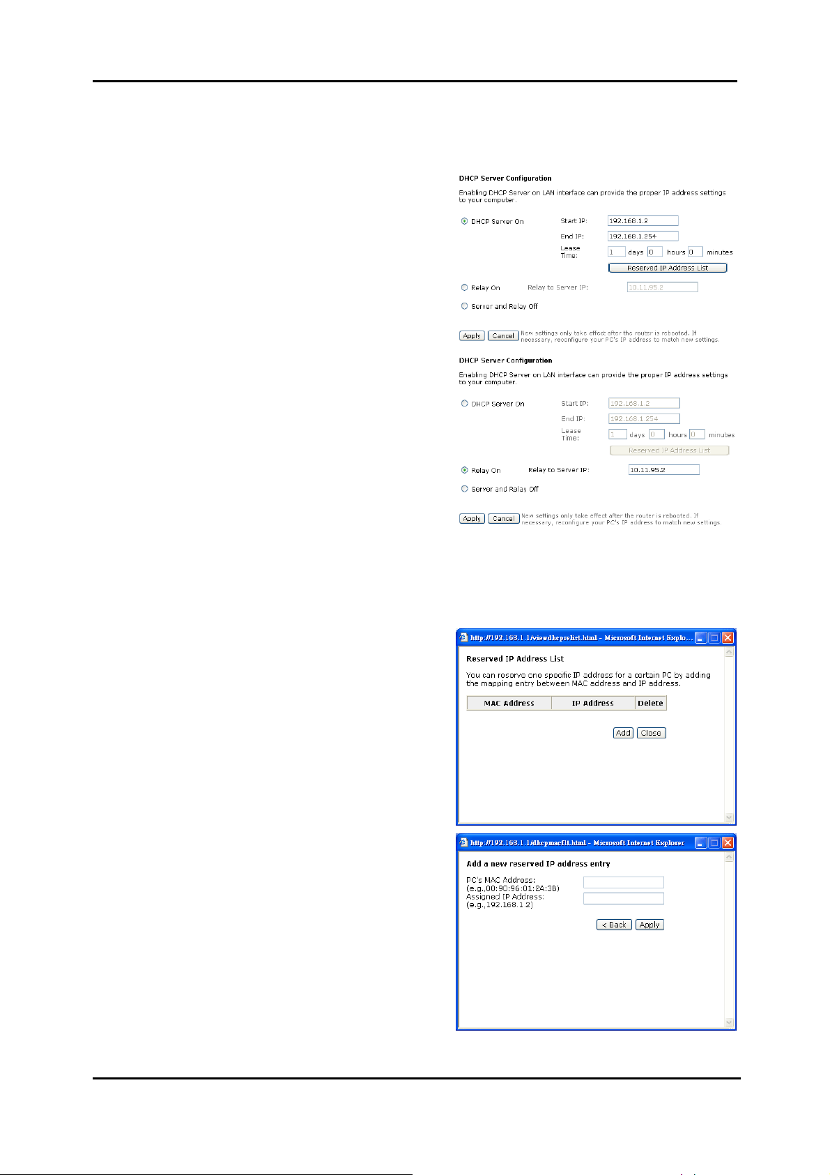
Chapter 4: Web Configuration
Local Network – DHCP Server
This allows you to set DHCP server on LAN interface.
DHCP Server On:
Check this item if DHCP service is
needed on the LAN. The router will
assign IP address and gateway
address for each of your PCs.
You have to key in Start IP Address,
End IP Address, and Lease Time.
The default lease time is 1day.
Relay On:
Click this button to have a relay
setting. And type the Server IP in the
IP field.
When the DHCP server is served by
another device rather than the router
itself, you can relay to that specific
server and enter the IP address of it,
as 10.11.95.2 in our example.
Server and Relay Off:
Check this item if DHCP service isn’t
needed on the LAN.
Apply:
Click this button to activate the
settings listed above.
You can reserve one specific IP
address for a certain PC for particula r
purpose. Simply add a mapping entry
of MAC address & IP address for that
PC by pressing the Reserved IP
Address List button. The window as
the one shown in the right column will
appear.
Click the Add button to open another
dialog window , shown as the right. On
PC’s MAC Address and Assigned IP
Address boxes, please type the
correct information according to your
need and click Apply.
81
Page 95
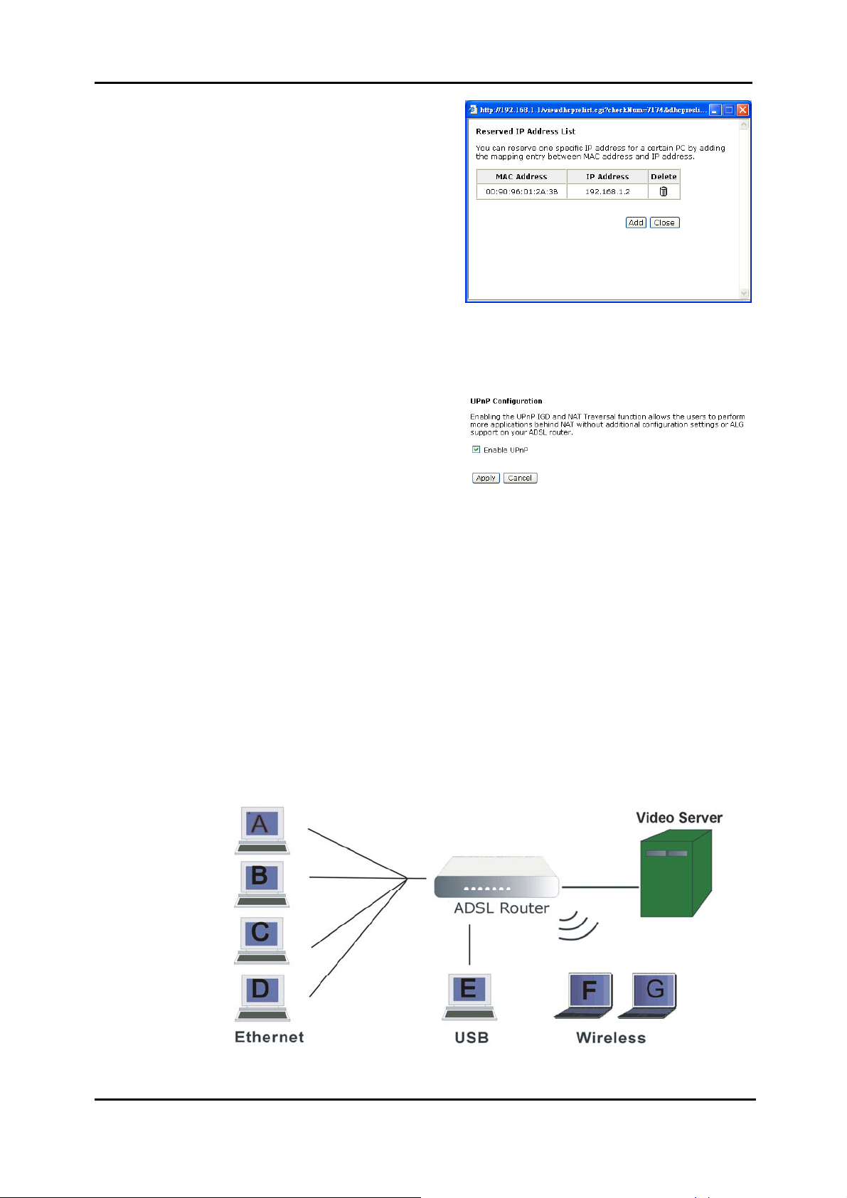
ADSL Router User Manual
The information added will be shown
on the window right away, as the right
figure illustrates. That is, the specified
address will be reserved and not be
assigned by DHCP for other
computer(s).
You may click Add button to add
another set or click Close to exit.
Local Network – UPnP
The UPnP is only available for Windows XP. If you are not a Windows XP user, you
may ignore this page.
Enabling the UPnP IGD and NAT
traversal function allows the users to
perform more applications behind NAT
without additional configuration
settings or ALG support on your ADSL
Router.
You can enable the UPnP function
through this web page by checking
Enable UPnP and press Apply.
Local Network – IGMP Snooping
Traditionally, IP packets are transmitted in one of either two ways - Unicast (1 sender
to 1 recipient) or Broadcast (1 sender to everyone on the network). Multicast delivers
IP packets to just a group of hosts on the network.
Without IGMP snooping, multicast traffic is treated in the same manner as broadcast
traffic, that is, it is forwarded to all ports. With IGMP snooping, multicast traffic of a
group is only forwarded to ports that have members of that group. IGMP snooping
generates no additional network traffic, allowing you to significantly reduce multicast
traffic passing through your switch.
The figure below shows a simple network connected via this ADSL router. There are
four Ethernet clients, one using USB, and two wireless clients.
82
Now suppose the video server is the multicast transmitter and host A and D are
multicast receivers. If we do not turn on the IGMP snooping function, the router will
Page 96

Chapter 4: Web Configuration
forward the multicast traffic to all hosts on all interfaces and consequently block and
interrupt the traffic of USB and wireless users, shown as the following figure.
When IGMP snooping is invoked, it makes the system aware to establish the best
path for multicast service to save LAN bandwidth. Refer the figure below, just as
desired, only host A and D will actually receive multicast traffic when IGMP snooping
is enabled.
While IGMP snooping is enabled, the IGMP packets will be monitored, the
membership information will be recorded and processed, and the multicast traffic will
only be forwarded to those LAN interfaces, such as Ethernet, Wireless, and USB,
which are bonded to the subscribed multicast groups. Thus it helps to save the
bandwidth and helps the devices to perform more effectively.
Check Enable IGMP Snooping and
click Apply to invoke this function.
When IGMP Snooping is enabled, you
can check the box below to filter out
multicast packets which will be sent to
your local network if no user plays
multimedia movies.
If the PVC you’re using is NAT
enabled, remember to turn on the
IGMP Proxy at the same time. Please
refer to Internet – IGMP Proxy for
more information.
Note that the IGMP proxy must be enabled
first. If the IGMP Snooping function is not
available as shown in the following figure,
you have to enable the IGMP Proxy first.
83
Page 97

ADSL Router User Manual
Internet – Connections
To set WAN settings for each service, please open Advanced– Internet. This page
allows you to edit, to remove, or to add WAN settings.
If you click the Connect
under the PVC Name item, the system
will connect to WAN automatically. If
the WAN connection is OK, you can
check the detailed information directly.
You can add new PVC(s) by clicking
the Add button, edit the settings for
the present PVC by clicking
Edit column, or delete the existing
PVC by pressing
Adding a New One
To add a new WAN connection, please click the Add button. The following screen
appears.
VPI (Virtual Path Identifier):
Identifies the virtual path between
endpoints in an ATM network. The
valid range is from 0 to 255. Please
refer to the value that your ISP
provides.
VCI (Virtual Channel Identifier):
Identifies the virtual channel endpoints
in an ATM network. The valid range is
from 32 to 65535 (1 to 31 is reserved
for well-known protocols). Please refer
to the value that your ISP provides.
hyperlink
in the
icon.
Service Category:
It decides the size and rate for the
packets of the data in different service
type. There are five categories
provided here for your selection,
shown as the drop-down menu in the
right column.
If you select UBR with PCR or CBR,
you have to offer the value for the
peak cell rate.
If you choose Non Realtime VBR, or
Realtime VBR, you have to key in the
value for the peak cell rate,
sustainable cell rate, and maximum
burst size.
As you can see in the right figure, the
range for Peak Cell Rate is from 1 to
2500; the value for Sustainable Cell
Rate ranges from 1 to 2499 and must
be smaller than Peak Cell Rate, and
the range for Maximum Burst Size is
from 1 to 1000000.
84
Page 98

After pressing Next, you will see the
web page listed as the right one.
Choose the protocol that you would
like to use. (Here provides the
example for PPPoA.)
Please refer to Quick Setup for more
information if you don’t know how to
set the configuration.
You can check Enable QoS to
improve performance for selected
applications. More detailed information
for QoS will be introduced in later
instruction.
If you choose PPPoE (or Bridging),
you will see the option for 802.1Q
VLAN T aggi ng.
802.1Q VLAN Tagging:
802.1Q-compliant switch ports can be
configured to transmit tagged or
untagged frames. A tag field
containing VLAN (and/or 802.1p
priority) information can be inserted
into an Ethernet frame. If a port has an
802.1Q-compliant device attached
(such as another switch), these
tagged frames can carry VLAN
membership information between
switches, thus letting a VLAN span
multiple switches. However, it is
important for network administrators to
ensure ports with
non-802.1Q-compliant devices
attached are configured to transmit
untagged frames. Many NICs for PCs
and printers are not 802.1Q-compliant.
If they receive a tagged frame, they
will not understand the VLAN tag and
will drop the frame. Also, the
maximum legal Ethernet frame size for
tagged frames was increased in
802.1Q (and its companion, 802.3ac)
from 1,518 to 1,522 bytes.
Chapter 4: Web Configuration
Notice that 802.1Q VLAN
Tagging function can only be
invoked under PPPoE and
Bridging Mode; the system will
not provide this option while
setting PPPoA or IPoA mode.
After checking Enable 802.1Q VLAN
Tagging, you will have to enter a
VLAN ID, as shown in the figure.
VLAN ID:
The VLAN Identifier is a 12 bit field. It
uniquely identifies the VLAN to which
the frame belongs to and can have a
value between 0 and 4095.
Click Next to continue.
85
Page 99

ADSL Router User Manual
The WAN IP settings page will differ
slightly according to the protocol that
you choose. The graphic is the one
that you will see if you choose the
PPPoE mode in the previous step.
You can select Enable NAT or change
the MTU value according to your
needs.
Add Default Route:
Check this item to add a default route.
The next figure following the WAN IP
Settings in the PPPoE mode is shown
at the right. You may refer to the
Quick Setup for further information.
If you choose IP over ATM from the
Connection T ype web page, you will
get a web page as the figure.
You may refer to Quick Start –
Connection Type – IPoA section for
more information.
Add Default Route:
Check this item to add a default IPoA
route.
For example, after rebooting your
router, the default route will be shown
on the Routing Table under Status
menu, you may check it.
If you choose Bridging from the
Connection T ype web page, you will
get a web page as the figure listed at
the right side.
Please refer to Quick Setup for more
information.
After configuring the WAN IP Setting
page, press Next, and then you will
see the Summary page.
86
Check the information displayed here.
Enable this Internet Connection:
Check the box to enable this internet
connection or uncheck it to disable
this setting. You may change this
setting by press the Modify icon
the Advanced – Internet Connection
Configuration page and click Next until
the summary page is displayed.
on
Page 100
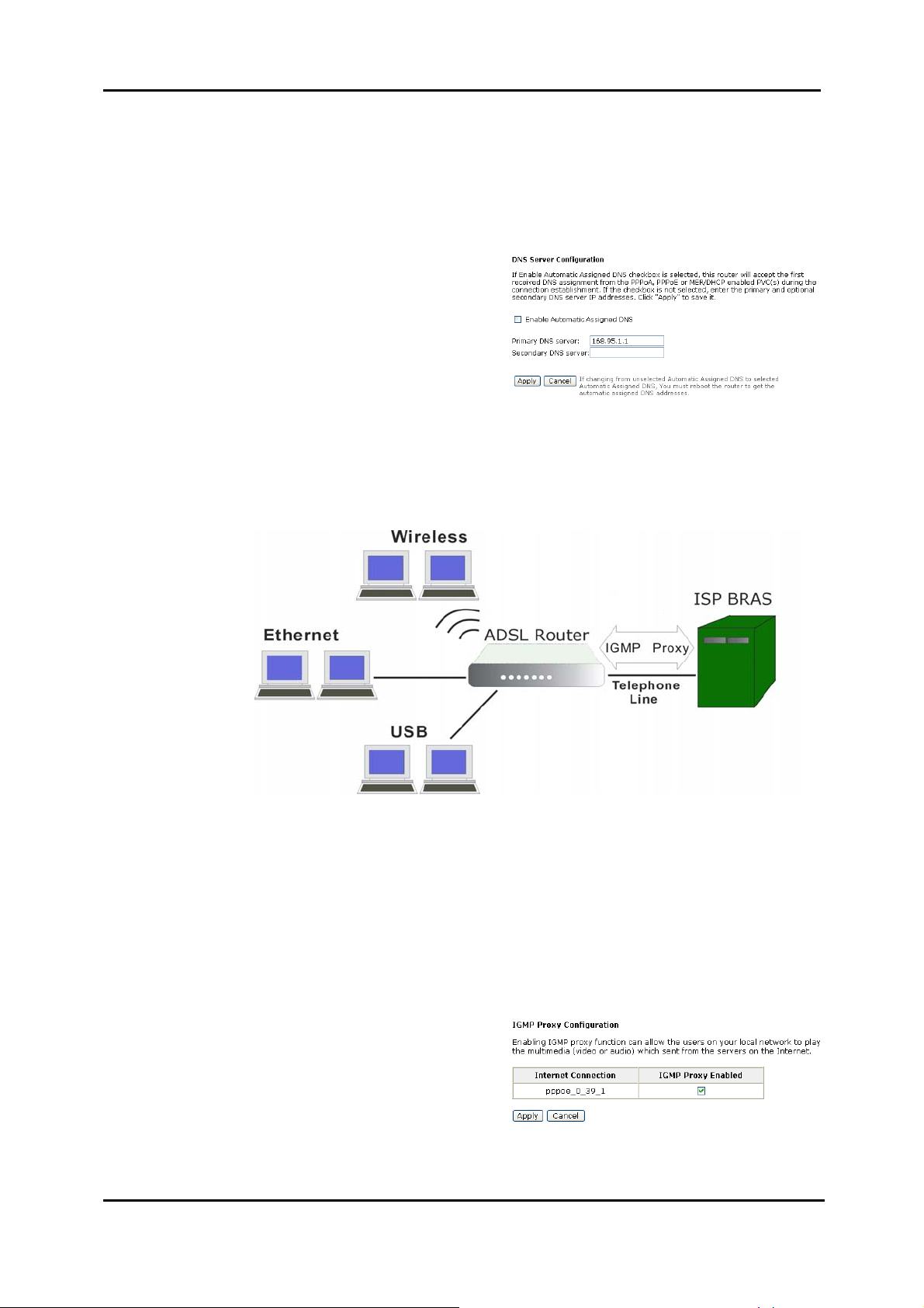
Chapter 4: Web Configuration
Internet – DNS Server
If Enable Automatic Assigned DNS checkbox is selected, this router will accept
the first received DNS assignment from one of the PPPoA, PPPoE or MER/DHCP
enabled PVC(s) during the connection establishment. If the checkbox is not selected,
it is necessary for you to enter the primary and optional secondary DNS server IP
addresses. Finish your setting and click the Apply button to save it and invoke it.
Enable Automatic Assigned DNS:
Check this box to enable this function,
or uncheck this box to disable it. The
default setting is checked. When this
function is disabled, you have to offer
the Primary DNS server and
Secondary DNS server.
If you are satisfied with the settings,
click Apply.
Internet – IGMP Proxy
The Internet Group Management Protocol (IGMP) is an Internet protocol that
provides a way for an Internet computer to report its multicast group membership to
adjacent routers.
The hosts interact with the system through the exchange of IGMP messages. When
you want to configure IGMP proxy, the system will interact with other routers through
the exchange of IGMP messages. However, when acting as the proxy, the system
performs the host portion of the IGMP task as follo ws:
¾ When being queried, the system will send membership reports to the group.
¾ When one of the hosts joins a multicast address group which none of other
hosts belongs to, the system will send unsolicited membership reports to that
group.
¾ When the last host in a particular multicast group leaves the group, the system
will send a leave group membership report to the router’s group.
Internet Connection:
This field displays the internet
connection(s) that set in this router.
IGMP Proxy Enabled:
Check this box to enable this function
or uncheck this box to disable this
function.
After finish the settings, click Apply.
To invoke the IGMP Snooping function,
the IGMP Proxy must be enabled first.
87
 Loading...