

Page 1
DYNALI HELICOPTER COMPANY
10, rue de la science,1400 - Nivelles Belgique
Tel : +32 (0) 67 55 29 98 Fax : +32 (0) 67 84 05 31
Mail : [email protected]
_________________________________________________________________________
FLIGHT MANUAL
Kit helicopter
Ref : DYNH2S/01/01/T01
Page 2

FLIGHT MANUAL DYNALI HELICOPTER COMPANY Edition N°3
DYNALI H2S January 2012
__________________________________________________________________________________
2
Copyright © by Dynali Helicopter Company, Nivelles, Belgium
This document is protected by copyright. All associated rights, in particular those of
translation, reprinting, web transmission, reproduction by photo-mechanical or similar
means and storing in data processing facilities, in whole or part, are reserved.
Dynali Helicopter Company
10, Rue de la Science
1400, Nivelles
Belgium
Tel : +32 (0) 67 55 29 98
Fax : +32 (0) 67 84 05 31
E-mail : [email protected]
Page 3

FLIGHT MANUAL DYNALI HELICOPTER COMPANY Edition N°3
DYNALI H2S January 2012
__________________________________________________________________________________
3
INTRODUCTION
RECORD OF REVISIONS
The validity of this flight manual is dependent on the punctuality with which it is
updated. The signature of the person responsible for the assembly of the kit provides
a guarantee of updates for himself and for other users. The composition of the
manual is given in the list of current pages.
RECORD OF REVISIONS
REVISIONS
INCORPORATED
number
dated
on
by
signature
00
Original
Edition
January 2009
01
July 2010
02
January 2011
03
January 2012
Page 4

FLIGHT MANUAL DYNALI HELICOPTER COMPANY Edition N°3
DYNALI H2S January 2012
__________________________________________________________________________________
4
TECHNICAL FOLLOW-UP
For your own safety and that of other users, you should take the habit of regularly consulting
the “Technical Publications” section of the Dynali Helicopter Company website
www.dynali.com. You will find there :
general information from Dynali Helicopter Company
technical modifications to be made to the helicopter
future planned evolution
new associations, clubs and meetings.
The objective of this flight manual is to provide you with the technical parameters which will
enable you to benefit from your helicopter under optimum conditions.
RECOMMENDATIONS
The main purpose of this manual is to focus on safety.
Please take the time to read it attentively.
It is essential to warn you about several risks that are too often underestimated or neglected
through force of habit and to provide you with the experience acquired by the whole family of
pilots of light helicopters.
We have therefore placed on the first pages the warnings that all pilots must constantly bear
in mind.
A helicopter is, by its nature, a capricious and unstable machine which is subject to both the
laws of the air and of physics. Furthermore, its mechanical components comprise a total
chain which is both complex and precise. It requires care and maintenance. Please study
carefully the specific characteristics and the recommendations which follow. These are
derived directly from the authorities responsible for the study of accidents. They summarise
the major causes of accidents involving light helicopters.
CHARACTERISTICS SPECIFIC TO LIGHT HELICOPTERS
- Low inertia of the rotor (this is not the case with the Dynali H2S).
- Rotor rocking ; sudden movement of the cyclic stick or certain flight conditions with light
loading may cause the rotor to rock to the limit, which may cause fracture of the rotor mast
(mast bumping).
- Relatively low reserve power in certain conditions such as transition phases, high altitude
flight or air conditions : high temperature, turbulence,…
- Maximum loading suddenly attained and a marked difference between the aircraftʼs
characteristics in solo flight and heavy dual flight.
- A piston engine has little inertia ; with the slightest drop in engine speed the rotor will
“freewheel”. In icing conditions, for example, the engine may simply stop as compared with a
Page 5

FLIGHT MANUAL DYNALI HELICOPTER COMPANY Edition N°3
DYNALI H2S January 2012
__________________________________________________________________________________
5
fixed wing aircraft which will still be provided with thrust for a moment by its propeller. The
governor system may hide the early stages of icing.
PRINCIPAL CAUSES OF ACCIDENTS IN LIGHT HELICOPTERS
- Over-confidence of pilots with great experience on other types and who believe, wrongly,
that a light helicopter is a very forgiving machine.
- Insufficient awareness of the limitations of the machine.
- Flare-out at too low altitude (engine failure or in training).
- Transition phase with the helicopter : impossibility of lateral correction and prevention of
lateral rollover. Dynamic rollover can sneak up on you.
- Loss of rotor RPM in the event of failure of governor.
PRIMARY SAFETY RECOMMENDATIONS
In the event of a risk of overturning on the ground (dynamic rollover) lower
immediately the collective control and also press down the pedal on the side of the
tipping.
Stabilise hover at 3ft prior to departure (hover recommended at between 3ft and
3,5ftm)
Best flight conditions are above VPM and at sufficient altitude.
Cruise above 1000ft.
Speed both in climb and cruise at over 60kts (always above VPM).
In the event of a reduction in rotor RPM, lower the collective immediately and
increase fuel-flow.
Auto-rotation training should be undertaken over a known surface and under
favourable conditions, mass, light headwind, temperature.
If you are flying solo (and unless you are undergoing instruction by a Dynali H2S
qualified instructor), limit autorotation exercises and open the throttle at 150ft. Avoid
sudden inputs to the controls.
Sufficient power while flying at a high altitude.
PILOT CODE
Keep both hands on the controls especially when close to the ground, (it is prohibited
to release the collective control and even more so the cyclic stick when in immediate
proximity to the ground).
Concentrate ! Be attentive at all times as nothing is ever sure. Beware of over
confidence.
Never fly if you are not feeling in perfect shape. In no case fly when you are
influenced by alcohol, lack of sleep or stress…
Danger if thereʼs an obligation to fly, demonstration flights, obligation to go from point
A to point B, flying through bad weather.
Pre-flight check and check out (always conduct these vital procedures with the
greatest rigour).
No risky flying ! Machine in perfect condition, engine idling smooth. At the slightest
unusual noise or vibration or any other doubt, interrupt the start-up procedure and
check.
No risky or unusual manoeuvres.
Page 6

FLIGHT MANUAL DYNALI HELICOPTER COMPANY Edition N°3
DYNALI H2S January 2012
__________________________________________________________________________________
6
Veterans beware! Almost half of all light helicopter accidents occur with pilots
unaccustomed to these types but who have more than 1000 hours flying time on
larger machines.
Do not land in long grass :
Danger for the fans
Danger of snagging the undercarriage skids
Fire risk danger : the exhaust may set fire to the grass.
ALWAYS THINK OF YOUR SAFETY DURING FLIGHT AND BE AWARE OF THE
LOCAL POSSIBILITIES FOR AUTO-ROTATION.
WHEN FLYING IN MOUNTAINOUS REGIONS THINK OF YOUR CLEARANCE AT
ALL TIMES AND WATCH YOUR RPM, ESPECIALLY DURING SHORT FINAL
APPROACH !
Landing and taking off among trees places you in danger for a short time. It is up to you to
evaluate the risks. Always calculate a safe trajectory and bear in mind the possibility of
engine failure.
REDUCTION OF MENTAL FACULTIES IN FLIGHT (HUMAN FACTORS)
It should be remembered that, in flight, we are not in our natural element. Our analytical
capacity is reduced by unconscious stress and this becomes more severe in the event of
problems as we lose part of our faculties. We no longer notice factors which worsen the
situation (obstacles, loss of RPM,…) and we easily accumulate errors. In flight, our analytical
capacity is reduced by half.
Accidents are always the consequence of an accumulation of circumstances.
All possible sources of failures must be studied with an instructor.
OTHER RISK FACTORS…
With a heavy payload, limitations are more restricted.
Wind shifts and other aerial phenomena must be taken into account.
The vortex danger : descending too fast and catching up with your own turbulence.
The rotor operates in turbulent air and loses a large part of its lift. This phenomenon
is present at all altitudes : 10,000 or 10 feet. A too rapid vertical descent or a forward
moving descent with a tail wind. Descending between obstacles while moving slowly
forward and with a light tail wind!!
The « buzzing » of friendʼs homes, which is the first cause of crash.
Reduced power margin.
Theoretical example : If the power when stationary is X, the transition to forward flight
requires additional power, thus equal to a minimum of X + y, if the transition is commanded
too suddenly and with too much amplitude towards forward flight, the power demand may be
greater than the available reserve of power. Conversely, if you transition from hover to
forward flight with gentle movements of the controls you will cause your aircraft to accelerate
into forward flight with very little extra power.
Theoretical example : you fly one circuit and you land. If you slow down too quickly with a
high sink rate on the vertical speed indicator, you may lack the power to stop your aircraft in
hover position. Always opt for a safe final approach with a vertical speed indicator showing
Page 7

FLIGHT MANUAL DYNALI HELICOPTER COMPANY Edition N°3
DYNALI H2S January 2012
__________________________________________________________________________________
7
less than 100ft/min on a short final taking care to monitor the power progressively prior to
hover (it is worth noting that at the correct power calculated for hover already set at 10ft from
the ground, the helicopter will settle by inertia at the correct height for the hover, i.e. 3ft).
Theoretical example : You arrive at a high altitude field and it is hot. You have consumed part
of the fuel and, pre-flight you have studied the altitude/mass/temperature charts.
Theoretically you are within the safe limits but stay wary all the same and watch your rotor
RPM during short final. If the low RPM warning lights up, break away downwards while
slightly lowering the collective to recover the lost rotor revs.
Never forget that:
An accumulation of factors may lead to an increased need for power.
Power limits make flying the helicopter more delicate. Takeoff and landing must be
performed gently while always using techniques which use the least possible power.
To be learned by heart:
In case of engine failure, lower the collective to the limit, use the left pedal to avoid a
yaw to the right, attain safe speed as quickly as possible and a trajectory which will
bring you to a safe landing spot. During descent, take care to manage your rotor
RPM. Flare out to stationary position followed by applying pitch control input one or
several times to soften your contact with the ground. (Never forget that a good flare
perfectly controlled and a non-sliding landing will themselves take care of your
safety). Even if the final is late or early, if you avoid a sliding landing you have every
chance of emerging intact after your engine failure).
If the rotor RPM greatly exceeds the normal operating range, do not panic. This does
not mean that you should ignore the RPM during auto-rotation. On the contrary, these
must be checked by the pilot but if, in a short final at the end of the flare-out, you
exceed the upper limit of the rotor RPM, no panic, continue your auto-rotation. Once
the landing has been completed, and depending on the extent of the excess RPM,
you should ask for technical assistance or expert advice.
Note : in the context of the hours of flight instruction with the instructor, mast bumping will be
studied theoretically on the ground only.
Page 8

FLIGHT MANUAL DYNALI HELICOPTER COMPANY Edition N°3
DYNALI H2S January 2012
__________________________________________________________________________________
8
To avoid doubt when to increase or decrease fuel flow,
MORE FINGERS = MORE FUEL
(meaning the side of the throttle grip where the four fingers are placed)
LESS FINGERS = LESS FUEL
(meaning the side of the throttle grip where the thumb is placed)
Page 9

FLIGHT MANUAL DYNALI HELICOPTER COMPANY Edition N°3
DYNALI H2S January 2012
__________________________________________________________________________________
9
TABLE OF CONTENTS
CHAPTER 1 –GENERAL…………………..……………………………………………..11
1.1. CHARACTERISTICS AND PERFORMANCE…………………………………………………………..14
1.2. DESCRIPTIVE DATA…………………………………………………………………………..…………14
1.3. ABREVIATIONS AND DEFINITIONS – MISCELLANEOUS…………………………………….……16
1.4. ABREVIATIONS AND DEFINITIONS – PERFORMANCE…………………………………………....16
1.5. ABREVIATIONS AND DEFINITIONS – MASS AND BALANCE…………………………….……….17
1.6. ABREVIATIONS AND DEFINITIONS – CONVERSION TABLE…………………………….……….18
CHAPTER 2 – UTILISATION LIMITS………………………………………………..….19
2.1. GENERAL…………………………………………………………………………………………...……..20
2.2. COULOUR CODE FOR MARKINGS ON INSTRUMENTS……………………………………..…….20
2.3. ENVIRONMENTAL LIMITS…………………………………………………………………………...….20
2.4. SPEED LIMITS………………………………………………………………………………………...…..20
2.5. MARKINGS ON AIRSPEED INDICATOR…………………………………………………….……..….21
2.6. LIMITS AND RELATIONSHIP BETWEEN ROTOR AND ENGINE REVS……………………….….21
2.7. MARKINGS ON ROTOR AND ENGINE REVS COUNTERS…………………………………………21
2.8. VIBRATIONS AND HARMONICS………………………………………………………………….……22
2.9. LIMITS ON THE DS25 ENGINE……………………………………………………………………..…..22
2.10. LIMITS RELATING TO OIL………………………………………………………………………..…....22
2.11. LIMITS RELATING TO FUEL………………………………………………………………………..…23
2.12. MARKINGS ON ENGINE INSTRUMENTS…………………………………………………………...23
2.13. MASS AND BALANCING LIMITS…………………………………………………………………..….24
2.14. LIMITS ON IN-FLIGHT MANŒUVRES………………………………………………………………..24
2.15. LIMITATIONS ON TAKEOFF…………………………………………………………………………..25
2.16. LIMITATIONS ON LANDING ON SLOPES……………………………………………………...……26
2.17. LIMITATIONS ON LOAD FACTORS………………………………………………………………......26
2.18. LIMITATIONS IN CASE OF FAILURE OF GOVERNOR…………………………………………….27
2.19. COCKPIT PLACARDS…………………………………………………………………………………..27
CHAPTER 3 – EMERGENCY PROCEDURES………………………...……………….29
3.1. GENERAL………………………………………………………………………………………………….30
3.2. ENGINE FAILURE – GENERAL…………………………………………………………………………30
3.3. ENGINE FAILURE ABOVE 500FT………………………………………………………………………30
3.4. ENGINE FAILURE AT LOW ALTITUDE………………………………………………………………..30
3.5. ENGINE FAILURE AT LOW ALTITUDE AND LOW SPEED…………………………………………31
3.6. FAILURE OF GOVERNOR……………………………………………………………………………….31
3.7. BEST AERODYNAMIC EFFICIENCY DURING AUTOROTATION………………………………….31
3.8. ENGINE RE-START PROCEDURE……………………………………………………………………..31
3.9. EMERGENCY DITCHING WITHOUT POWER………………………………………………………..31
3.10. EMERGENCY DITCHING WITH POWER…………………………………………………………….32
3.11. REAR TRANSMISSION OR ROTOR FAILURE DURING TRANSITION………………………….32
3.12. REAR TRANSMISSION OR ROTOR FAILTURE DURING HOVER……………………………….32
3.13. ENGINE FIRE DURING STARTUP……………………………………………………………………32
3.14. ENGINE FIRE IN FLIGHT……………………………………………………………………………….32
3.15. LIGHTING UP INDICATORS…………………………………………………………………………...33
Page 10

FLIGHT MANUAL DYNALI HELICOPTER COMPANY Edition N°3
DYNALI H2S January 2012
__________________________________________________________________________________
10
CHAPTER 4 – NORMAL PROCEDURES………………………………………………35
4.1. NORMAL OPERATING SPEED…………………………………………………………………………36
4.2. PREFLIGHT INSPECTION AND CHECKS………………………………………………………….....36
4.3. CHECKLISTS : WARNINGS……………………………………………………………………………..37
4.4. ENGINE START…………………………………………………………………………………………...38
4.5. TAKEOFF…………………………………………………………………………………………………..38
4.6. CRUISE…………………………………………………………………………………………………….39
4.7. APPROACH AND LANDING……………………………………………………………………………..39
4.8. AUTOROTATION………………………………………………………………………………………….40
4.9. ENGINE SHUTDOWN PROCEDURE…………………………………………………………………..41
4.10. CHECK OUT……………………………………………………………………………………………...41
CHAPTER 5 – PERFORMANCES…………………………………………………….…42
5.1. GENERAL………………………………………………………………………………………………….43
5.2. CALIBRATION OF AIRSPEED INDICATOR…………………………………………………………...44
5.3. ALTITUDE / DENSITY TABLE…………………………………………………………………………...45
5.4. CEILING FOR HOVER IN GROUND EFFECT………………………………………………………...46
5.5. CEILING FOR HOVER OUTSIDE GROUND EFFECT………………………………………………..47
5.6. DISTANCE / ALTITUDE RATIO USING AUTOROTATION…………………………………………..48
5.7. HEIGHT SPEED DIAGRAM……………………………………………………………………………...49
5.8. NOISE LEVEL……………………………………………………………………………………………..50
CHAPTER 6 – MASS AND BALANCE…………………………………………….……51
6.1. GENERAL……………………………………………………………………………………………...…..52
6.2. MASS AND BALANCE…………………………………………………………………………….……...52
6.3. HELICOPTER LOADSHEET……………………………………………………………………………..58
6.4. LATERAL BALANCING…………………………………………………………………………………..59
CHAPTER 7 – SYSTEMS…………………………………………………………………61
7.1. GENERAL…………………………………………………………………………………….……………62
7.2. CABIN SHELL…………………………………………………………………………………...………...62
7.3. UNDERCARRIAGE………………………………………………………………………………………..62
7.4. MAIN ROTOR……………………………………………………………………………………...………62
7.5. REAR TURBINE OR ANTI-TORQUE ROTOR…………………………………………………….…..62
7.6. TRANSMISSIONS…………………………………………………………………………………………63
7.7. ENGINE…………………………………………………………………………………………………….63
7.8. FLIGHT CONTROLS…………………………………………………………………………...…………63
7.9. ENGINE – CLUTCH – DRIVE BELTS………………………………………………………….……….64
7.10. FUEL CIRCUIT………………………………………………………………………………….………..64
CHAPTER 8 – HANDLING AND MAINTENANCE…………………………..…….…..65
8.1. GENERAL………………………………………………………………………………………………………………..66
8.2. REQUIRED DOCUMENTS…………………………………………………………………..………………….……..66
8.3. MAINTENANCE…………………………………………………………………………………………………………66
8.4. MODIFICATIONS TO THE HELICOPTER……………………………………………………..…………………….67
8.5. MANŒUVRES ON THE GROUND…………………………………………………………………………………...67
8.6. PARKING AND TIEING DOWN…………………………………………………………………..…………………...67
8.7. MAINTENANCE AND PROCEDURES…………………………………………………………..…………………...67
8.8. MAINTENANCE AND SERVICE LIFE…………………………………………………………..……………………67
Page 11

FLIGHT MANUAL DYNALI HELICOPTER COMPANY Edition N°3
DYNALI H2S January 2012
__________________________________________________________________________________
11
CHAPTER 1 – GENERAL
1.1. CHARACTERISTICS AND PERFORMANCE
1.2. DESCRIPTIVE DATA
1.3. ABREVIATIONS AND DEFINITIONS – MISCELLANEOUS
1.4. ABREVIATIONS AND DEFINITIONS – PERFORMANCE
1.5. ABREVIATIONS AND DEFINITIONS – MASS AND BALANCING
1.6. ABREVIATIONS AND DEFINITIONS – CONVERSION TABLES
Page 12
FLIGHT MANUAL DYNALI HELICOPTER COMPANY Edition N°3
DYNALI H2S January 2012
__________________________________________________________________________________
12
Page 13
FLIGHT MANUAL DYNALI HELICOPTER COMPANY Edition N°3
DYNALI H2S January 2012
__________________________________________________________________________________
13
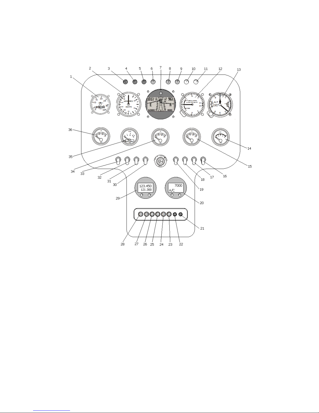
Instrument panel (Note: instrument panels vary according to specification and
customer needs)
1 : Manifold pressure
2 : Airspeed indicator
3 : General warning
4 : Generator charge indicator
5 : Low RPM indicator
6 : Low Fuel indicator
7 : Engine/Rotor dual RPM
8 : Chip detector MTG
9 : Chip detector RTG
10 : FAN 1
11 : FAN 2
12 : Vertical speed indicator
13 : Altimeter
14 : External T°
15 : Coolant liquid T°
16 : Free swtich
17 : Free switch
18 : Free switch
19 : Free switch
20 : Transponder
21 : Free fuse
22 : Free fuse
23 : Instruments
24 : Engine
25 : Fuel pump 1
26 : Fuel pump 2
27 : Fan 1
28 : Fan 2
29 : VHF
30 : Free switch
31 : Free switch
32 : Free switch
33 : Governor ON/OFF
34 : Oil Pressure
35 : Fuel gauge
36 : MTG oil T°
Page 14

FLIGHT MANUAL DYNALI HELICOPTER COMPANY Edition N°3
DYNALI H2S January 2012
__________________________________________________________________________________
14
1.1. CHARACTERISTICS AND PERFORMANCE
Dimensions
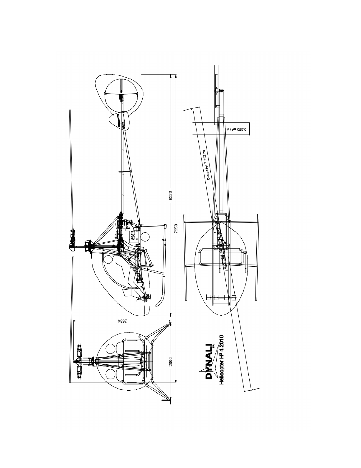
Main rotor - Diameter................................................................................... 7,16 m
Number of blades .................................................................................................2
Anti-torque rotor - Diameter ............................................................................ 0,8 m
Number of blades .................................................................................................8
Fuselage length ............................................................................................6,23 m
Overall length (including reach of main rotor)............................................... 7,95 m
Height............................................................................................................ 2,58 m
Undercarriage width .................................................................................... 2,00 m
Cabin interior width .......................................................................................1,45 m
Power plant
Engine........................................................................................... Subaru DS EJ25
Capacity ................................................................................................... 2500 cm³
Max power output ........................................................................................ 180 HP
Hourly fuel consumption ................................................................................ 27 L/h
Total fuel capacity ............................................................................................. 90 L
Useable fuel capacity..................................................................................... 87,5 L
Unusable fuel capacity..................................................................................... 2,5 L
Performance
Autonomy at 27L/h.................................................................. ......................03h10
Practical useable ceiling ..................................3500 / 4000 m ........ 11500/13150 ft
VNE.......................................................................... 190 km/h ...................... 102 kt
Cruising speed ............................................... 140 à 165 km/h ...............75 to 90 kt
Rate of climb (dependent on payload) …150 to 300m/min……...500 to 1000ft/min
1.2. DESCRIPTIVE DATA
Main rotor
Semi-rigid type, on teetering hinge, without trailing articulations.
Number of blades...................................................................................................2
Diameter ....................................................................................................... 7,12 m
Constant blade chord.................................................................................. 0,195 m
Blade tortion......................................................................................................... 6°
Blade mass ..................................................................................................... 12 kg
Blade tip speed at 100% of nominal capacity ....................... 735 km/h at 530 RPM
Rear or anti-torque rotor
Rigid type, no flapping articulations, fully housed
Number of blades...................................................................................................8
Diameter .................................................................................................... 0,840 m
Surface area of disc ...................................................................................0,554 m²
Constant blade chord.................................................................................. 0,055 m
Blade twisting....................................................................................................... 5°
Mass of blade....................................................................................................78 g
Blade tip speed at 100% of nominal capacity ..................... 608 km/h at 3833 RPM
Page 15

FLIGHT MANUAL DYNALI HELICOPTER COMPANY Edition N°3
DYNALI H2S January 2012
__________________________________________________________________________________
15
Transmission
Main transmission and main transmission box MTG
Transmission by gearing R=2,43
Secondary transmission by 8 trapezoidal belts R=1.27
Main transmission shaft ..................................... hardened stainless steel AISI 431
Diameter ....................................................................................................... 35 mm
Free wheels in upper pulley, number :...................................................................2
Dynali main transmission box : ……............1 conic helicoid spiral type gear R=35
Rear transmission and rear transmission box
Rear transmission by shaft. Cardan joint type coupling
Rear rotor transmission shaft........ hardened stainless steel AISI 431 diameter 12
Diameter ....................................................................................................... 12 mm
Rear transmission box: .........................................1 conic helicoid spiral type gear
Reduction ratio rear transmission box : N transmission shaft / N rear rotor .......1/2
Reduction ratio
N engine / N main rotor .................................................................................9,83/1
N rear rotor / N main rotor..............................................................................7,09/1
Power-plant
Engine........................................................................................... Subaru DS EJ25
Horizontally opposed « flat » 4 cylinders 4 stroke. Electronic injection.
Liquid cooled. “Dry” sump (separate oil tank).
Cylinder capacity....................................................................................... 2500 cm³
Maximum power output................................................................................180 HP
Engine RPM at maximum power ............................................................5300 RPM
Fuel
Regular fuel........................................................... 95 or 98 octane automobile fuel
Occasional fuel ................................................................................AVGAS 100 LL
Note : AVGAS 100LL or Ethanol may be used as regular fuel subject to
modification of the injectors.
Hourly fuel consumption: ............................................................................... 27 L/h
Total fuel capacity: ............................................................................................ 90 L
Useable fuel capacity:.................................................................................... 87,5 L
Unusable fuel capacity..................................................................................... 2,5 L
Low fuel warning ............................................................. below 10L of useable fuel
Cooling and lubrication
Liquid engine coolant
Type ............................................................................................................... Glycol
Capacity : ............................................................................................................ 9 L
Engine oil (change every 6 months or 100 hours)
Type ..................... oil for gasoline engine, synthetic or semi-synthetic SAE 10W50
Capacity .......................................................................................................... 3,5 L
Page 16

FLIGHT MANUAL DYNALI HELICOPTER COMPANY Edition N°3
DYNALI H2S January 2012
__________________________________________________________________________________
16
Main transmission oil
Type ............................................................................................ hypoid SAE 75/90
Capacity ........................................................................................................... 2,5 L
Rear transmission oil
Type ........................................................................................... hypoid SAE 70/90
Capacity ........................................................................................................ 125 ml
1.3. ABREVIATIONS AND DEFINITIONS – MISCELLANEOUS
MTG : Main Transmission Gearbox
RTG : Rear Transmission Gearbox
ATR : Anti-Torque rotor
RT : Rear Transmission
1.4. ABREVIATIONS AND DEFINITIONS – PERFORMANCES
IAS - Indicated air speed
Speed shown on the air speed indicator, i .e. relative to the air in which the
aircraft is flying. Expressed in kilometers per hour or knots [km/h - kts].
VNE
Maximum safe speed. Above this speed, the aircraft will exceed its mechanical
design limits.
Expressed in kilometres per hour or knots [km/h - kts].
Vy ou Vpm
Speed providing maximum power. Speed which gives the optimum rate of climb.
Speed expressed in kilometers per hour or knots [km/h - kts]. Rate of climb
expressed in [m/s] or [ft/min].
Manifold pressure
Current pressure in the engine intake manifold, expressed in column inches of
mercury [inHg].
MCP
Maximum Continuous Power.
RPM
Revolutions (Revs)/Rotations per minute. Unit used to express the speed of the
main rotor and of the engine. Both of these are indicated on the rev. counters on
the control panel.
Page 17

FLIGHT MANUAL DYNALI HELICOPTER COMPANY Edition N°3
DYNALI H2S January 2012
__________________________________________________________________________________
17
International Standard Atmosphere
Atmosphere model for which the sea-level pressure is equal to 1013.25 hPa, the
sea level temperature is at 15°C and the temperature gradient is at -6,5°C per
1000m (3000ft) of altitude. The air is considered as an ideal gas.
1.5. ABREVIATIONS AND DEFINITIONS – WEIGHT AND BALANCE
Datum : Reference point for balancing
As regards calculations, the Dynali design office has chosen the axis of the main rotor
as the datum.
Station : Distance from the datum point to the centre of gravity of a component.
C.G. : Centre of gravity (Point from which the helicopter would balance, if suspended).
Balancing :
Horizontal distance from the CG of the component concerned in relation to the datum point.
Balancing limits
Distance limits from the CG for which use of the helicopter may be operated at a given
mass.
Standard empty weight
Weight of helicopter in standard configuration, with unusable fuel reserve, full operating
fluids and full engine oil.
Basic empty weight
Standard empty weight to which is added the weight of all optional equipment.
Payload
Difference between maximum takeoff weight and basic empty weight.
Unusable fuel
Fuel which can not be used in flight.
Page 18

FLIGHT MANUAL DYNALI HELICOPTER COMPANY Edition N°3
DYNALI H2S January 2012
__________________________________________________________________________________
18
1.6. ABREVIATIONS AND DEFINITIONS – CONVERSION
TABLE
UNITS
Symbol
Conversion
Distance
metre
m
1 m = 3.3 ft
centimetre
cm
1 cm = 0,01 m
millimetre
mm
1mm = 0,001 m
hectometre
hm
1 hm = 100 m
kilometre
km
1 km = 0,540 NM = 1000 m
Nautical Mile
NM
1 NM = 6076 ft = 1852 m
Statute Mile
SM
1 SM = 1609 m
inch
in
1 in = 0,0254 m
foot (plur: feet)
ft
1 ft = 12 in = 0,3048 m
yard
yd
1 yd = 3 ft = 0,9144 m
Speed
knot
kts
1 kt = 1 NM/h = 1,852 km/h
feet/minute
ft/min
100 ft/min = 0,508 m/s
Weight
kilogram
kg
1 kg = 2,2 lbs
pound
lbs
1 lb = 0,454 kg
Volume
litre l 1 l = 1,055 qt = 0.264 USG
millilitre
ml
1 ml = 0,001 l
quart
qt
1 qt = 0,25 USG = 0,9475 l
US Gallon
USG
1 USG = 4 qts = 0,833 ImpG = 3,79 l
Imperial Gallon
ImpG
1 ImpG = 1,20 USG = 4,54 l
Pressure
pascal
Pa
1 Pa =
hectopascal
hPa
1 hPa = 100 Pa
bar
bar
1 bar = 105 Pa
Inches Mercury
In Hg
1 In Hg =
Power
Horsepower
HP
1 HP = 0,736 kW
Kilowatt
kW
1 kW = 1,397 HP
Page 19

FLIGHT MANUAL DYNALI HELICOPTER COMPANY Edition N°3
DYNALI H2S January 2012
__________________________________________________________________________________
19
CHAPTER 2 – UTILISATION LIMITS
2.1. GENERAL
2.2. COULOUR CODE FOR MARKINGS ON INSTRUMENTS
2.3. ENVIRONMENTAL LIMITS
2.4. SPEED LIMITS
2.5. MARKINGS ON AIRSPEED INDICATOR
2.6. LIMITS AND RELATIONSHIP BETWEEN ROTOR AND ENGINE REVS
2.7. MARKINGS ON ROTOR AND ENGINE REVS COUNTERS
2.8. VIBRATIONS AND HARMONICS
2.9. LIMITS ON THE DS25 ENGINE
2.10. LIMITS RELATING TO OIL
2.11. LIMITS RELATING TO FUEL
2.12. MARKINGS ON ENGINE INSTRUMENTS
2.13. MASS AND BALANCING LIMITS
2.14. LIMITS ON IN-FLIGHT MANŒUVRES
2.15. LIMITATIONS ON TAKEOFF
2.16. LIMITATIONS ON LANDING ON SLOPES
2.17. LIMITATIONS ON LOAD FACTORS
2.18. LIMITATIONS IN CASE OF FAILURE OF GOVERNOR
2.19. COCKPIT PLACARDS
Page 20

FLIGHT MANUAL DYNALI HELICOPTER COMPANY Edition N°3
DYNALI H2S January 2012
__________________________________________________________________________________
20
2.1. GENERAL
Chapter 2 deals with the limits on use, the markings on the instruments, and the main
placards required for the safe operation of the helicopter, its engine and its other systems.
2.2. COLOUR CODING FOR MARKINGS ON INSTRUMENTS
Green
Normal operating range.
Yellow
Operating range requiring close attention.
Red
Indicates limits of operation. The needle should not enter the red zone during
normal operation.
2.3. ENVIRONMENTAL LIMITS
Temperature Limits
The Dynali H2S may be operated between -15 °C and +45 °C, except in icing or supercooling conditions.
Wind limits
Start-up in steady wind
Headwind ....................................................................................................... 35 kts
Crosswind ...................................................................................................... 25 kts
Tailwind ......................................................................................................... 15 kts
Start-up in gusting wind
Headwind .............................................................................................. 20 to 30 kts
Crosswind ...................................................................................................... 15 kts
Tailwind.......................................................................................................... 15 kts
Note : Always try to startup facing into the wind (this is almost always possible with a
helicopter)
2.4. SPEED LIMITS
VNE (Speed not to be exceeded )
Altitudes below 1000 m-3000 ft
VNE (with or without power) .......................................... 190 km/h .............. 102 kts
Altitudes from 1000 to 1500 m-3000 ft to 4500 ft
VNE (with or without power) ..........................................180 km/h ................ 97 kts
Above 1500 m-4500 ft
VNE............................................ decreases by 12 km/h - 6 kts per 1000m - 3000ft
Maximum speed with 1 or 2 doors removed .......................... 150 km/h ................ 81 kts
Page 21
FLIGHT MANUAL DYNALI HELICOPTER COMPANY Edition N°3
DYNALI H2S January 2012
__________________________________________________________________________________
21
Doors may be opened in flight up to.......................................... 30 km/h ................ 16 kts
2.5. MARKING ON THE AIRSPEED INDICATOR
Green line (Vpm)............................................................110 km/h ................ 60 kts
Green arc ...............................................................90 à 185 km/h ...... 50 à 100 kts
Red line (VNE) ............................................................... 190 km/h .............. 102 kts
2.6. LIMITS AND RELATIONSHIP BETWEEN ENGINE AND ROTOR
SPEEDS
LIMITS ON ROTOR / ENGINE OUTPUT
ROTOR
ENGINE
% [RPM]
[RPM]
Nominal output
100
530
5300
Low RPM with power
92
496
4960
Max RPM with power (5 min max)
106
571
5710
Low RPM freewheel flight
92
500
0
Maxi RPM freewheel flight
112
600
0
Maximum rotor rate......................................................................112 % - 600 RPM
Maximum engine rate (over-speed limiter operates) ..................106% - 5800 RPM
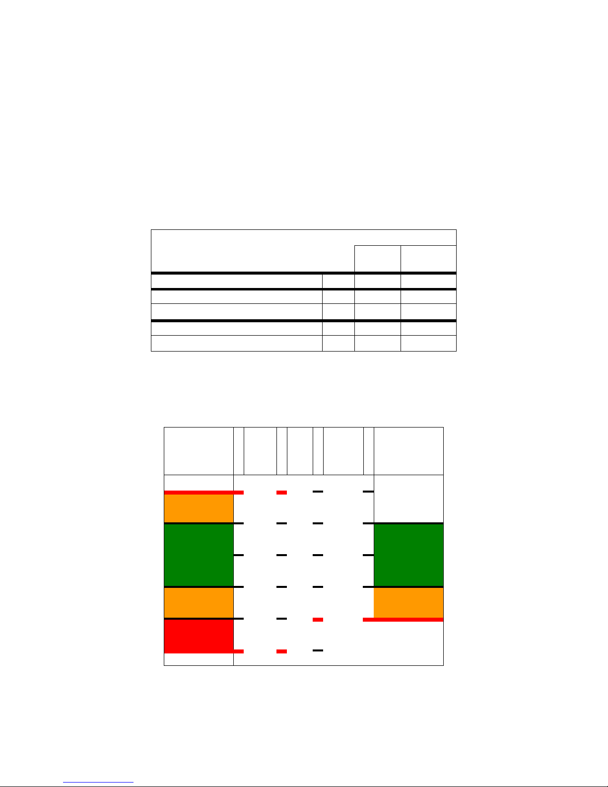
2.7. MARKINGS ON ROTOR AND ENGINE REV. COUNTERS
Rotor
Rev. Counter
Rotor
%
Engine
Engine
Rev. Counter
[RPM]
[RPM]
Red line
496
92
4960
Yellow zone
517
96
5170
530
100
5300
Green zone
Green zone
555
103
5550
Yellow zone
Yellow zone
571
106
5710
Red line
Red zone
Red line
600
112
Page 22

FLIGHT MANUAL DYNALI HELICOPTER COMPANY Edition N°3
DYNALI H2S January 2012
__________________________________________________________________________________
22
2.8. VIBRATIONS AND HARMONICS
On startup, while the engine revs are increasing, momentary vibrations occur
between 270 and 310 RPM. These engine rev levels should be passed without delay.
In normal flight, the Dynali H2S is not vibrating at all.
2.9. LIMITATIONS ON THE SUBARU DS EJ25 ENGINE
Engine limitations indicated in the Subaru manual or its appendices apply wherever
these may differ from the indications provided (for information purposes only) in this
flight manual.
Climatic conditions for engine start
Minimum temperature....................................................................................-15 °C
Maximum temperature.................................................................................... 45 °C
Output
Maximum engine output (engine speed limiter operates) .........106 % - 5710 RPM
Temperature of cooling fluid
Caution range ........................................................................................70 to 75 °C
Nominal range.........................................................................................75 to 95°C
Caution range ......................................................................................95 to 106 °C
Maximum ......................................................................................................106 °C
Engine oil pressure
Red warning light for low pressure................................................................1,5 bar
2.10. LIMITATIONS RELATING TO OIL
Engine oil
Type .................... Oil for gasoline engine, synthetic or semi-synthetic SAE 10W50
Capacity .............................................................................................................. 3L
Oil for MTG
Type ............................................................................................ hypoid SAE 85/90
Capacity ............................................................................................................ 2,5L
MTG oil temperature
Green zone ............................................................................................. until 95°C
Red zone .............................................................................................. 95 to 120°C
Maximum…………………………………………………………………………...150°C
Oil for RTG
Type .......................................................................................hypoid SAE 75 W 90
Capacity ........................................................................................................ 125 ml
Page 23

FLIGHT MANUAL DYNALI HELICOPTER COMPANY Edition N°3
DYNALI H2S January 2012
__________________________________________________________________________________
23
2.11. LIMITATIONS RELATING TO FUEL
Type of fuel
Regular fuel.................................................... 95 or 98 automobile gasoline octane
Occasional fuel .............................................................. AVGAS 100 LL or Ethanol
Note : AVGAS 100LL or Ethanol may be used as regular fuel provided that the injectors are
modified.
Hourly consumption: ......................................................................................27 L/h
Total fuel capacity: ............................................................................................ 90 L
Total usable fuel capacity: .............................................................................87,5 L
Non-usable fuel capacity.................................................................................. 2,5 L
Fuel remaining warning light ............................................... below 10L useable fuel
Note : The low fuel warning (LOW FUEL, orange light on control panel) lights up when there
remains less than 10L of usable fuel, or less than 20 minutes flying time before engine
failure.
2.12. MARKINGS ON ENGINE INSTRUMENTS
Intake manifold pressure
Green zone .....................................................................................20 to 29,5 in Hg
Note : as from 29,5 inHg manifold pressure in standard atmosphere, at sea level, the engine
supplies maximum power and there is therefore a greater reserve of power should the
unexpected occur.
Rotor rev. counter
Red line: ................................................................................................... 496 RPM
Yellow zone ................................................................................... 496 to 517 RPM
Green zone .................................................................................... 517 to 555 RPM
Yellow zone ................................................................................... 555 to 571 RPM
Red zone ....................................................................................... 571 to 600 RPM
Red line .....................................................................................................600 RPM
Engine rev. counter
Green zone ................................................................................ 5300 to 5550 RPM
Yellow zone ............................................................................... 5550 to 5710 RPM
Red line .................................................................................................. 5710 RPM
Note : the green zone on the engine rev counter corresponds to the green zone on the rotor
rev counter
Coolant temperature
Yellow zone............................................................................................70 to 75 °C
Green zone ............................................................................................ 75 to 95°C
Yellow zone .........................................................................................95 to 106 °C
Red line ..........................................................................................................106°C
Page 24

FLIGHT MANUAL DYNALI HELICOPTER COMPANY Edition N°3
DYNALI H2S January 2012
__________________________________________________________________________________
24
MTG temperature
Green zone ............................................................................................below 95°C
Yellow zone............................................................................................95 à 120°C
Red line ..........................................................................................................120°C
Fuel gauge
Red zone.......................................................................... less than 15L usable fuel
2.13. WEIGHTS AND BALANCING LIMITS
HANGING LOAD TOTALLY PROHIBITED ! A load which starts to swing like a pendulum
may bring the helicopter into an unusual attitude; in this event, the rotor may reach the limit of
the teetering hinge. This may cause fracture of the rotor mast.
Limitations of weight (see Chapter 6)
Maximum takeoff weight at sea level ............................................................ 700 kg
Standard empty weight .................................................................................465 kg
Maximum weight in cabin................................................................(see Chapter 6)
Minimum weight of pilot in solo flight .............................................................. 60 kg
Maximum weight of pilot in solo flight ................................ (see Chapter 6) 135 kg
Maximum weight in baggage compartment .................................................... 26 kg
Limitations of balancing (see Chapter 6)
2.14. LIMITATIONS ON MANŒUVRES IN FLIGHT
- Daylight VFR flight is permitted.
- Night VFR flight is prohibited with CNSK2 registration.
- IFR flight is prohibited with CNSK2 registration.
- Aerobatics are prohibited.
- Flight in icing or snowing conditions is prohibited..
- Maximum altitude density for operation is 4000 m
- Transport capability : 2 persons on board, including pilot.
- Solo flight : the pilot must use the left hand seat.
- Safety belts must be fastened both on an empty seat and on the pilotʼs seat.
- Flight with one or both doors removed is authorised..
- With doors removed, all objects in the cabin must be attached..
- Wearing of a helmet is strongly recommended.
Note : Even within the EASA countries, certification requirements differ. Worldwide, the H2S
may be registered under CNSK, CNRA, LSA, experimental, amateur built or other national
regulatory systems. Dynali can supply all documentation required by certifying authorities
Depending on the agreements reached in each country concerned, the H2S may fly at night
and even under IFR conditions with special equipment (control panel lighting, navigation
lights, strobe lights, two artificial horizons, (1 pneumatic, 1 electrical) landing light, mode C
transponder, VHF radio, distress beacon.
This type of certification, negotiated in each country, can be justified by the technical
specification and the performance of the H2S.
Page 25

FLIGHT MANUAL DYNALI HELICOPTER COMPANY Edition N°3
DYNALI H2S January 2012
__________________________________________________________________________________
25
Turning and banking
Banking between 10° and 45° (desirable range in normal use)
It has been demonstrated that at a speed above 2/3 Vpm, or 40 kts, in a 45°
angle of bank coordinated turn the machine does not lose altitude during the first
60° of turn. As from 60° additional collective should be applied to compensate for
sinking.
Banking between 45° and 90° (extreme range, not advisable for beginners !)
It has been established that a turn at 90° bank is the equivalent of +3,5G load
factor.
2.15. LIMITATIONS ON TAKEOFF
Dynamic rollover is always lateral.
When the collective is in the extreme lower position, the point of balance is at around 45°
inclination. When the collective is pulled up to the limit for takeoff, the balance point is at no
more than 10° inclination because the rotor is exercising a pull.
Take care always to take off gently, making sure that the skids leave the ground vertically.
There is a moment of risk during takeoff.
If the pilot fears a suction effect on the skids (frost, mud, entangling vegetation) he must take
care to takeoff with first the left skid. As soon as this detaches from the ground, the pilot
brings the cyclic back to the centre position to release the right skid.
Dynamic capsizing is treacherous as it starts gently. When placing in hover, the stick takes a
too large lateral corrective position. Initiation of the hover should be immediately interrupted
and lower the collective. The pilot should then seek out the reason or reasons that the skid
has been held on the ground and not attempt a further lift off until he is aware of all the
causes of the problems. Prior to initiating the takeoff again, he should check the following
points :
- Is the balancing correct ?
- Is the passenger in the right hand seat too heavy ?
- Is the crosswind too strong ?
- Is the slope beyond the operating limits of the machine ?
- Is there an obstacle blocking the skid on the ground ?
Page 26

FLIGHT MANUAL DYNALI HELICOPTER COMPANY Edition N°3
DYNALI H2S January 2012
__________________________________________________________________________________
26
2.16. LIMITATIONS ON LANDING ON SLOPES
Forwards (i.e. tail downhill) ................................................................................ 15°
Lateral right (i.e. bottom of the slope on the right) .................................... 10 to 12°
Lateral left (i.e. bottom of the slope on the left).................................................... 8°
Note : these conditions should be avoided as far as possible. Prefer landing at 45°. (see
below)
Backwards (i.e. tail uphill) .................................................................. PROHIBITED
Note : when obliged to land on sloping ground, always try to land at 45° to the axis of the
slope. You will reduce the risk of dynamic rollover.
2.17. LIMITATIONS TO LOAD FACTOR (mast bumping)
AS WITH ALL TWO BLADE ROTOR HELICOPTERS, THE DYNALI H2S CAN NOT FLY
WITH A ZERO OR NEGATIVE LOAD FACTOR AS THIS CAN RESULT IN A
CONFIGURATION WHICH CAUSES MAST BUMPING.
The rotor flap is only (relatively) stable when its centre of gravity is lower than the axis of its
teetering hinge.
Furthermore, under a low or negative load factor, the helicopter is still pushed laterally by the
tail rotor and rolls over even faster on account of its low mass.
Mast bumping only occurs on twin rotor blade helicopters. It occurs when the load factor
moves from a level of +1G towards 0G. It is initiated as from +0,5G.
Mast bumping starts with a loss of lateral control of the helicopter from the thrust of the rear
rotor and may end with the fracture of the rotor mast.
! AVOID ALL SUDDEN TRANSITION FROM HORIZONTAL FLIGHT TO A DIVE BY
PUSHING THE CYCLIC FORWARD OR SUDDEN TRANSITION FROM CLIMB TO
HORIZONTAL FLIGHT.
! IN GENERAL AVOID ANY STRONG, SUDDEN CYCLIC MOVEMENTS IN LOW G
CONDITIONS AS THIS MAY PROVOKE PARTIAL WEIGHTLESSNESS (REDUCTION OF G
FORCES); IF A ROLL STARTS AT THAT TIME, PULL BACK GENTLY ON THE CYCLIC IN
ORDER TO REDUCE THIS LOSS OF G (which is the equivalent to re-loading the rotor)
BEFORE CORRECTING THE ROLL.
Note : during the instruction period, mast bumping will be studied in theory with the instructor
on the ground only.
Page 27

FLIGHT MANUAL DYNALI HELICOPTER COMPANY Edition N°3
DYNALI H2S January 2012
__________________________________________________________________________________
27
2.18. LIMITATIONS WITH FAILURE OF GOVERNOR
Flight with the governor out of service is authorised. In this event, the pilot must regulate the
engine RPM manually.
Note : The instructor responsible for issuing a Dynali H2S type rating must have included in
his training program, several exercises involving a failure of the governor.
2.19. COCKPIT PLACARDS
In sight of the pilot and the passenger:
SOLO PILOT IN LEFT HAND SEAT
THE HEAVIER OCCUPANT IN THE LEFT HAND SEAT
MINIMUM MASS FOR SOLO PILOT : 60 kg (see Flight Manual)
MAXIMUM MASS FOR SOLO PILOT WITHOUT BALLAST : 135 kg
MAXIMUM TAKEOFF WEIGHT : 700 kg
VFR flight in daylight authorised. Night flight and IFR flight prohibited. Flight in icing
conditions prohibited. Warning, this helicopter does not meet the conditions required for the
issuance of a normal airworthiness certificate and has not been built in the industrial
framework approved by the minister in charge of civil aviation. Commercial use of this
aircraft is prohibited.
PASSENGER WARNING
This aircraft was manufactured in accordance with Light Sport Aircraft airworthiness
standards and does not conform to standard category airworthiness requirements.
Page 28

FLIGHT MANUAL DYNALI HELICOPTER COMPANY Edition N°3
DYNALI H2S January 2012
__________________________________________________________________________________
28
Speed limits (VNE)
Altitudes below 1000 m (3000ft)
VNE (with or without power) ..........................................190 km/h .............. 102 kts
Altitudes from 1000 to 1500 m (3000ft to 4500 ft)
VNE (with or without power) ..........................................180 km/h ................ 97 kts
Above 1500 m (4500ft)
VNE............................................... decreases by12 km/h-6 kts per 1000 m-3000 ft
Flight with 1 or 2 doors removed is authorised.
Maximum speed : 150 km/h (80kts)
Doors may be opened in flight at or below 30 km/h (16kts)
Page 29

FLIGHT MANUAL DYNALI HELICOPTER COMPANY Edition N°3
DYNALI H2S January 2012
__________________________________________________________________________________
29
CHAPTER 3 – EMERGENCY PROCEDURES
3.1. GENERAL
3.2. ENGINE FAILURE – GENERAL
3.3. ENGINE FAILURE ABOVE 500FT
3.4. ENGINE FAILURE AT LOW ALTITUDE
3.5. ENGINE FAILURE AT LOW ALTITUDE AND LOW SPEED
3.6. FAILURE OF GOVERNOR
3.7. BEST AERODYNAMIC EFFICIENCY DURING AUTOROTATION
3.8. ENGINE RE-START PROCEDURE
3.9. EMERGENCY DITCHING WITHOUT POWER
3.10. EMERGENCY DITCHING WITH POWER
3.11. REAR TRANSMISSION OR ROTOR FAILURE DURING TRANSITION
3.12. REAR TRANSMISSION OR ROTOR FAILTURE DURING HOVER
3.13. ENGINE FIRE DURING STARTUP
3.14. ENGINE FIRE IN FLIGHT
3.15. LIGHTING UP INDICATORS
Page 30

FLIGHT MANUAL DYNALI HELICOPTER COMPANY Edition N°3
DYNALI H2S January 2012
__________________________________________________________________________________
30
3.1. GENERAL
Speed provides your reserve of potential energy. Altitude 1m in hover ; absolutely avoid
hovering above 2m (7ft). While in transition, speed and altitude are the keywords for safety.
Flare out allows you to convert speed into lift, while maintaining full rotor RPM. In the event of
the loss of rotor RPM, provided that a speed close to Vpm has been maintained, one can
always, using the flare effect, recover a large part of the lost rotor RPM. In all cases and for
all kinds of touring flight, you should always maintain a speed close to the Vpm. The
difference lies in the fact that in the second case, you will have no possible recourse in the
event of engine failure, see the height/speed diagram – every possibility of succeeding in an
auto-rotation landing in the first case)
Altitude gives you time during which you can retain control of your manœuvres. This time
also enables you, if things go wrong, to select a better landing ground.
A FLARE PROVIDES THE GREATEST AMOUNT OF AUTO-ROTATIVE ENERGY.
Auto-rotation procedure, see Chapter 4.
3.2. ENGINE FAILURE – GENERAL
• Loss of power may be caused by a failure of the engine or the transmission.
• A change in the noise level, a yawing or a drop in RPM may be the sign of an
engine failure.
• Transmission failure may be indicated by unusual noise or by vibrations and
major yawing. In all cases, initiate auto-rotation.
• Auto-rotation procedure, see Chapter 4.
3.3. ENGINE FAILURE ABOVE 500 ft
• Initiate auto-rotation immediately.
• Select landing area.
• Possibly attempt re-start (throttle to idle).
• Preferably land into the wind.
3.4. ENGINE FAILURE AT LOW ALTITUDE
Takeoff manœuvres must be undertaken according to the height/speed grid shown in
Chapter 5.
Page 31

FLIGHT MANUAL DYNALI HELICOPTER COMPANY Edition N°3
DYNALI H2S January 2012
__________________________________________________________________________________
31
3.5. ENGINE FAILURE AT LOW ALTITUDE AND LOW SPEED
If the Quick Stop is no longer possible, make a sliding landing :
• Left pedal down
• Above 1,5m (5ft), slightly lower the collective
• Below 1,5m (5ft), do not lower the collective
• Measured use of collective to cushion the contact with the ground.
3.6. GOVERNOR FAILURE
If the governor fails in flight, manually control the engine revs and reach a landing site
making an approach at a normal angle of descent.
The throttle control must be handled to ensure maximum power and RPM.
The co-relation throttle/pitch is not efficient enough at high altitude and great attention should
be paid to reducing throttle at the moment when the collective is lowered in order to avoid
excess engine speed.
Note : The H2S is equipped with a limiter for high motor RPM. Do not hesitate to give full
throttle if you are worried about the governor failure which has just occurred as, by doing this,
you will retain:
• full power
• rotor RPM
The only inconvenience of this is that the noise of the high RPM setting is characteristic as it
is linked to the injection system which, in this precise case de-synchronises the ignition which
gives the impression of miss-firing in the engine while actually providing maximum power.
3.7. BEST AERODYNAMIC EFFICIENCY IN AUTO-ROTATION
• Speed, around 110 km/h - 60 kts
• Rotor revs, around 95%.
3.8. ENGINE RE-START PROCEDURE
• Throttle to idle.
• Governor OFF.
• Start with left hand.
! DO NOT ATTEMPT RE-START IF ENGINE MISFUNCTION IS SUSPECTED OR WHEN
SAFE AUTO-ROTATION HAS NOT BEEN ESTABLISHED.
3.9. FORCED DITCHING WITHOUT POWER
• Auto-rotation procedure until contact with the water.
• Turn helicopter onto left side on contact with water in order to stop the rear
rotor.
Page 32

FLIGHT MANUAL DYNALI HELICOPTER COMPANY Edition N°3
DYNALI H2S January 2012
__________________________________________________________________________________
32
3.10. FORCED DITCHING UNDER POWER
• Position in hover over water.
• Unlock doors.
• Evacuate passenger.
• Move away from passenger downwind if the wind is strong (the passenger
will move towards the crash which may enable him to provide assistance
to the pilot)
• Throttle to idle, left foot down, slow the descent.
• Lay the helicopter on its left side on contact with the water in order to stop
the rear rotor.
3.11. FAILURE OF REAR ROTOR OR TRANSMISSION DURING
TRANSITION
Sudden yaw to the left which can not be corrected with the right pedal if speed below 100
km/h - 54 kts. (If speed above 100 km/h - 54 kts, the steering effect of the asymmetric
vertical stabiliser will ensure maintenance in the axis of the fuselage)
• Initiate auto-rotation immediately, then adjust power
• Maintain 110 km/h - 60 kts so that the steering effect of the tail remains
effective.
• Reduce throttle and slightly increase the collective. Hold the cyclic to the
right in order to limit the drift.
• On final, throttle to idle and sliding landing under auto-rotation.
3.12. FAILURE OF REAR TRANSMISSION OR ROTOR DURING
HOVERING FLIGHT
• Sudden yaw to the left that can not be corrected with the right pedal
• Throttle to idle and land under auto-rotation.
3.13. ENGINE FIRE DURING STARTUP
• If the engine starts, it may aspirate the flames and the excess fuel.
• If the engine does not start or if the fire does not immediately extinguish
itself, cut the engine and evacuate.
• Extinguish the fire with an extinguisher, a woolen covering or with earth or
sand..
3.14. ENGINE FIRE IN FLIGHT
• Descend rapidly in auto-rotation.
• If the engine is running, use the throttle and land normally.
Page 33

FLIGHT MANUAL DYNALI HELICOPTER COMPANY Edition N°3
DYNALI H2S January 2012
__________________________________________________________________________________
33
3.15. WARNING LIGHTS
Red lights Low rotor RPM - warning horn 92%
Action : lower the collective and twist the throttle grip through the governor to recover
immediately the lost RPM.
Several solutions are possible :
• You are at altitude: you have an altitude margin below the helicopter, you can thus
firmly lower the collective and twist the throttle to recover the revs.
• You are in mountains, close to terrain on short final and you can not lower the
collective on account of the terrain below the helicopter. In this case you must divert
immediately towards the valley while slightly lowering the collective and applying
throttle to recover the rotor revs.
In all events you should not continue the approach if you have a low RPM warning light.
Orange battery charge warning light
The alternator has failed. The electronic ignition of the engine is linked to the battery
and operates independently of the alternator.
Reduce power to avoid the activation of the cooling fans and land safely as soon as
possible.
Orange low fuel level warning light (Low fuel)
This warning lights up when there remains only 10 L of usable fuel. The engine will run
dry after approximately 20 minutes operation at nominal power.
ACTION : YOU MUST LAND AS SOON AS THIS WARNING LIGHTS UP, IN THE
FIRST AVAILABLE FIELD BELOW YOU.
Orange filings detector warning – main transmission box
This warning lamp lights up if metal particles are detected in the main transmission
box.
Action : you should land without undue urgency or precipitation within 5 minutes
Orange filings detector warning – rear transmission box
This warning lamp lights up if metal particles are detected in the rear transmission box
Action : you should land without undue urgency or precipitation within 5 minutes
Red warning indicator for low pressure in the cooling fluid.
This warning is activated if there is a leak of cooling fluid.
Action : you should land without undue urgency or precipitation within 5 minutes
Red warning indicator for low engine oil pressure :
Page 34

FLIGHT MANUAL DYNALI HELICOPTER COMPANY Edition N°3
DYNALI H2S January 2012
__________________________________________________________________________________
34
In normal operation, the engine oil pressure should remain between 1,5 and 5 bar. The
warning lights up if the oil pressure falls below 2 bar.
Action : you should land without undue urgency or precipitation within 5 minutes.
Page 35

FLIGHT MANUAL DYNALI HELICOPTER COMPANY Edition N°3
DYNALI H2S January 2012
__________________________________________________________________________________
35
CHAPTER 4 – NORMAL PROCEDURES
4.1. NORMAL OPERATING SPEED
4.2. PREFLIGHT INSPECTION AND CHECKS
4.3. CHECKLISTS : WARNINGS
4.4. ENGINE START
4.5. TAKEOFF
4.6. CRUISE
4.7. APPROACH AND LANDING
4.8. AUTOROTATION
4.9. ENGINE SHUTDOWN PROCEDURE
4.10. CHECK OUT
Page 36

FLIGHT MANUAL DYNALI HELICOPTER COMPANY Edition N°3
DYNALI H2S January 2012
__________________________________________________________________________________
36
4.1. NORMAL OPERATING SPEED
Vpm – Minimum power speed .......................................110 km/h ................ 60 kts
Takeoff and climb speed................................................110 km/h ................ 60 kts
Optimal rate of climb ...................................................... 110 km/h ................ 60 kts
Economical level flight speed.........................................150 km/h ................ 81 kts
Landing approach ..........................................................110 km/h ................ 60 kts
Autorotation....................................................................110 km/h ................ 60 kts
Minimum speed on auto-rotation final (flare) : Vpm = 110 km/h - 60 kts
EXCEPT DURING TRAINING WITH AN INSTRUCTOR, ONLY THE PILOT HANDLES THE
CONTROLS. IN THE PASSENGER SEAT, THE PASSENGER SIDE CYCLIC STICK AND
THE PEDALS SHOULD NOT BE TOUCHED.
4.2. PRE-FLIGHT INSPECTIONS AND CHECKS
Takeoff area and environment
1. Clothing, rags and other polluting items. Nothing likely to fly into the rotors.
2. No human or animal presence at less than 20m.
3. Wind speed and direction.
4. No obstacles, takeoff flight path clear.
Airframe
1. Remove parking strap on rear facing main rotor blade.
2. Undercarriage : wheels removed or, failing that, locked.
3. Fuel tanks : check fuel level equal on both sides + check fuel tank caps closed.
4. Radiator and fans : check for grass or debris.
5. Check underside of engine, main transmission and generally on the ground under the
helicopter for signs of leaked oil, fuel, or coolant.
6. Check pitot correctly aligned forward.
7. Drive belts, correctly in position.
8. Blades : check full length.
9. Tail assembly : no foreign objects deposited there.
10. Rear transmission : check for leaks, oil level.
11. Rear rotor blades: appearance.
Inside cabin
12. No smell of fuel.
13. Pedals : control rods straight – split pin rod connectors vertical.
14. No loose objects.
15. Empty seat : seat belt fastened, not tangled in collective.
16. Passenger side door closed.
17. Instrument panel – check the zeros.
18. Controls free + full movement of controls.
19. Check that left hand collective in lower stop position brings central collective to lower
stop (guarantee for autorotation).
20. Throttle in idle position.
Page 37

FLIGHT MANUAL DYNALI HELICOPTER COMPANY Edition N°3
DYNALI H2S January 2012
__________________________________________________________________________________
37
4.3. CHECKLISTS : WARNINGS
Never fly directly after a mechanical intervention. Check free movement of controls before
start-up, check that all tools used during the maintenance have been removed. Start up in the
usual way and remain on the ground for some time before taking off and transitioning with
caution.
The principle of takeoff is the same as for an aeroplane. Think about the ambient conditions :
the fuel level and load as well as the aerological conditions, wind speed and direction. Check
the terrain and possible obstacles. Decide in advance on the best takeoff route. Start out
from the end of the field if necessary to provide room for acceleration. Intelligence and
concentration !
The engine may be started before settling in on board as it is a good idea to run the checklist
while it is warming up and to observe while it is idling.
(No passenger alone on board while engine running !)
Page 38

FLIGHT MANUAL DYNALI HELICOPTER COMPANY Edition N°3
DYNALI H2S January 2012
__________________________________________________________________________________
38
4.4. START-UP
Seatbelts
Fastened
Doors
Closed and locked
Switch Governor
ON
Fuel
Checked and calculated
Weight and balance
Checked and calculated
Throttle
Full idle
Ignition
ON
Light indicators
Check switched ON (charge, Press, low RPM
Fuses
Check switched OFF
Fuel pumps
Running
Rudder pedals
Checked
Cyclic plate
Tested on 3cm course
Area
Safe and clear
Starter
START, engage to 800RPM
Temptrature coolant liq.
Wait until 50°C
RPM
Increase to 3500RPM
Temperature coolant. liq.
Wait until 70°C
RPM
Increase to 5400RPM
Light low RPM
Check OFF
Free Wheel
Check by decreasing suddenly RPM
Instruments
Checked
Area
Clear
Note : in very cold climatic conditions, at least three minutes should be spent on the ground
with rotors turning at 100% to warm up the reduction gear and other bearings.
4.5. TAKE-OFF
Vibrations
Not present
Hovering flight
Controls free, balancing correct
RPM
Stable
Weight and balance
Checked
Controls
Normal, free, no shimmy
T°
Min 70°C
Pressure
Min……bar
Manifold pressure
Min……inHg
Controls
Normal, free, no shimmy
Translation flight
Cleared for flight
Page 39

FLIGHT MANUAL DYNALI HELICOPTER COMPANY Edition N°3
DYNALI H2S January 2012
__________________________________________________________________________________
39
4.6. CRUISE
Governor
Check reliability
Collective stick
Trimmed
Cyclic controls
Do not release
Instruments / Alarms
Monitor
External security
Regular
Altitude
Min. 500ft
Speed
80 to 90kts
RPM
Monitor
4.7. APPROACH AND LANDING
Always opt for an approach into the wind and check the direction of this while studying the
landing site.
POWER MANAGEMENT:
Reminders : climb parameters : power 100%, speed 100 km/h – 55 kts (possibility of 108% if
necessary for a few seconds).
Level flight parameters : maximum continuous power setting : 23 à 25 in PA and 165 km/h 90 kts
Flight parameters in descent : power as needed (in relation to the descent flight path
selected), 60 kts approach speed.
Page 40

FLIGHT MANUAL DYNALI HELICOPTER COMPANY Edition N°3
DYNALI H2S January 2012
__________________________________________________________________________________
40
4.8. AUTOROTATIONS
This is the most important manœuvre which it is essential to master completely
TRAINING EXERCISE:
(the complete engine shut down exercise must only be performed with the instructor)
- Establish a safe altitude (1000ft AGL – 300m AGL),
- Check safety below, both in front and on both sides,
- Lower the collective to bottom limit,
- Reach and maintain a speed of 100 to 110 km/h – 55 to 60 kts
- During descent, manage rotor RPM (if rotor speed too high, (use collective to bring the
needle of the rev counter to 100%, then return to bottom limit and repeat as necessary during
descent)
- At around 10/15m – 30/45 ft, commence flare by deliberate movement of the cyclic without
moving the collective
- Retain a non-skidding attitude as regards your anticipated impact point.
- On completing flare (at the precise moment that the tail starts sinking) flatten out, (still in
non-skidding attitude) and hold up the aircraft using the collective but without causing the
aircraft to climb.
- Accept that the progressive application of the collective results in a regular but slow loss of
altitude.
- Accept the lighting up of the low RPM warning light.
- Accept the sounding of the low RPM warning siren
- At around 30cm (1ft) from the ground (estimated height which can vary by +/- 20cm),
continue to apply the collective until contact established with the skids (still in non-skidding
attitude)
- THE INERTIA OF THE ROTOR OF THE H2S MUST BE MAINTAINED.
- THE DESIRED SPEED DURING DESCENT AND AT THE MOMENT OF INITIATION OF
THE FLARE MUST BE ABOVE VPM AND CLOSE TO 100 km/h – 55 kts.
- IT IS THE FLARE WIHCH WILL TRANSFORM AT THE INSTANT (during the flare and until
its completion) YOUR SPEED INTO LIFT SO AS TO STOP THE FORWARD MOVEMENT
OF YOUR AIRCRAFT.
- STOPPING IN THIS WAY TAKES EFFECT AT A DISTANCE FROM THE GROUND
APPROXIMATELY EQUAL TO THE DIAMETRE OF THE ROTOR WITHOUT HAVING
« USED UP » REVS (i.e. without having acted on the collective)
- AS FROM THE END OF THE FLARE AND LEVELLING OUT ALL THE KINETIC ENERGY
THAT CAN BE DELIVERED BY THE ROTOR CAN BE USED TO COMPLETE THE FINAL
AND TO LAND GENTLY.
- NEVER HOLD THE AIRCRAFT UP USING THE COLLECTIVE PRIOR TO THE FLARE.
Page 41

FLIGHT MANUAL DYNALI HELICOPTER COMPANY Edition N°3
DYNALI H2S January 2012
__________________________________________________________________________________
41
4.9. ENGINE SHUT DOWN PROCEDURE
After touchdown
Decrease collective
Collective
Full idls
Cyclic
Neutral
Rudder pedals
Neutral
RPM
Idle for 3 minutes
T°
Wait for decrease
Instruments
OFF
Ignition
OFF
Do not leave the seat while the rotor is turning.
When at a standstill, do not brake the rotor by raising the collective.
At low revs, the wind can cause the rotor blades to swing down to head height. All
movement of personnel under the rotor circumference at standstill is extremely dangerous. It
must be prohibited. (in the case where boarding or disembarking of a passenger is
necessary while the rotor is turning instruct your passengers to move away to the front of the
helicopter and keep very low)
e.g. : landing on a mountain or on unstable terrain which makes it impossible to stop the
engine.
4.10. CHECKLIST (following flight)
After cutting the engine :
Monitor the stopping time of the rotor.
Get into the habit of placing oneʼs hand on the RTG and to control the thermal stamp.
Page 42

FLIGHT MANUAL DYNALI HELICOPTER COMPANY Edition N°3
DYNALI H2S January 2012
__________________________________________________________________________________
42
CHAPTER 5 – PERFORMANCES
5.1. GENERAL
5.2. CALIBRATION OF AIRSPEED INDICATOR
5.3. ALTITUDE / DENSITY TABLE
5.4. CEILING FOR HOVER IN GROUND EFFECT
5.5. CEILING FOR HOVER OUTSIDE GROUND EFFECT
5.6. DISTANCE / ALTITUDE RATIO USING AUTOROTATION
5.7. HEIGHT SPEED DIAGRAM
5.8. NOISE LEVEL
Page 43

FLIGHT MANUAL DYNALI HELICOPTER COMPANY Edition N°3
DYNALI H2S January 2012
__________________________________________________________________________________
43
5.1. GENERAL
The agility of the helicopter has been demonstrated by crosswinds and tail winds of up to 35
kts at a mass of 700 kg on the ground
VNE : 190 km/h – 102 kts
VFR flight authorised
IFR flight prohibited for use under CNSK2 certification
Night flying prohibited for use under CNSK2 certification
Flight in icing conditions prohibited
Emergency Auto-rotation (see 4.10)
Use maximum revs in the range « with power » (100%) during takeoff and climb out (if
necessary 108%, limited to 10 minutes) then limit to 100%.
Page 44
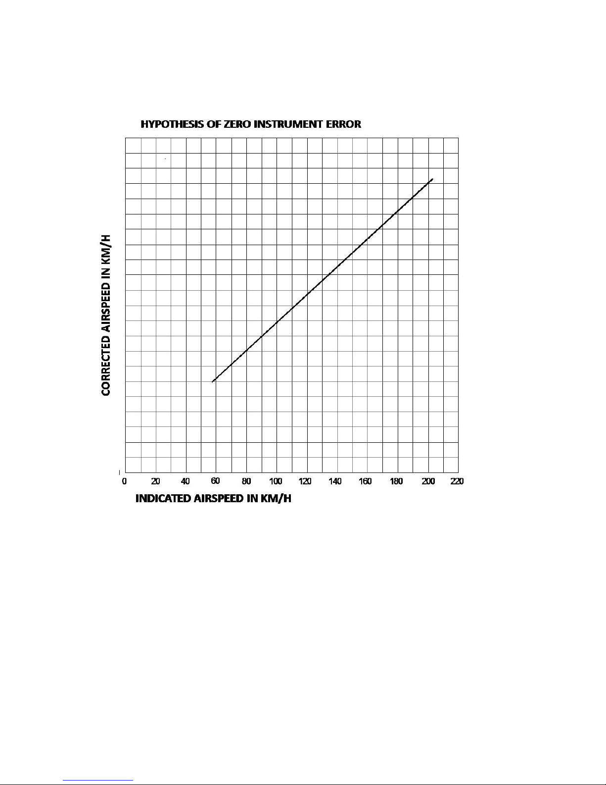
FLIGHT MANUAL DYNALI HELICOPTER COMPANY Edition N°3
DYNALI H2S January 2012
__________________________________________________________________________________
44
5.2. CALIBRATION OF AIRSPEED INDICATOR
Page 45
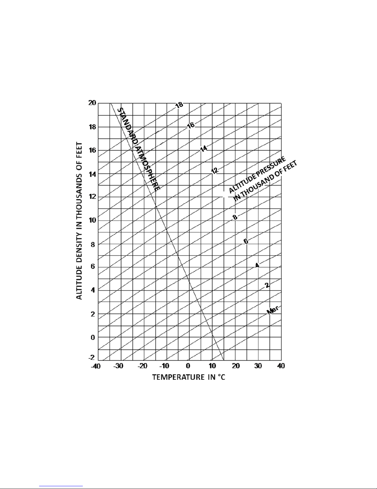
FLIGHT MANUAL DYNALI HELICOPTER COMPANY Edition N°3
DYNALI H2S January 2012
__________________________________________________________________________________
45
5.3. ALTITUDE / DENSITY TABLE
Page 46
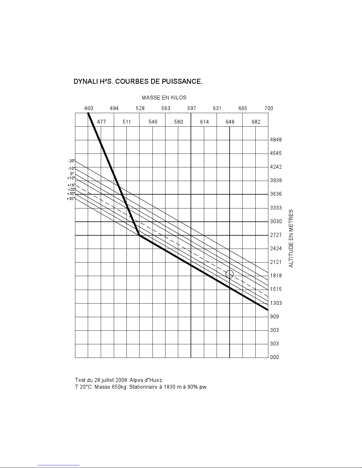
FLIGHT MANUAL DYNALI HELICOPTER COMPANY Edition N°3
DYNALI H2S January 2012
__________________________________________________________________________________
46
5.4. HOVER CEILING IN GROUND EFFECT
Page 47
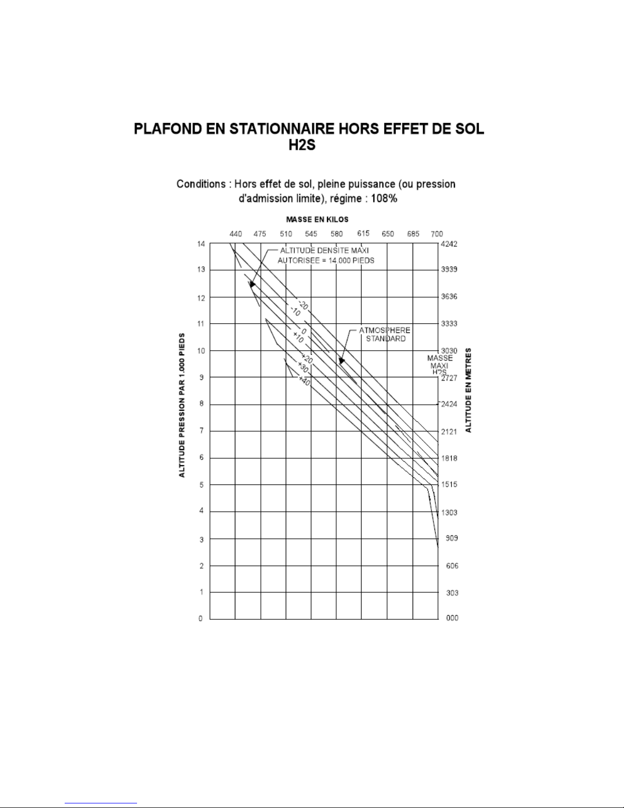
FLIGHT MANUAL DYNALI HELICOPTER COMPANY Edition N°3
DYNALI H2S January 2012
__________________________________________________________________________________
47
5.5. HOVER CEILING OUTSIDE GROUND EFFECT
Page 48
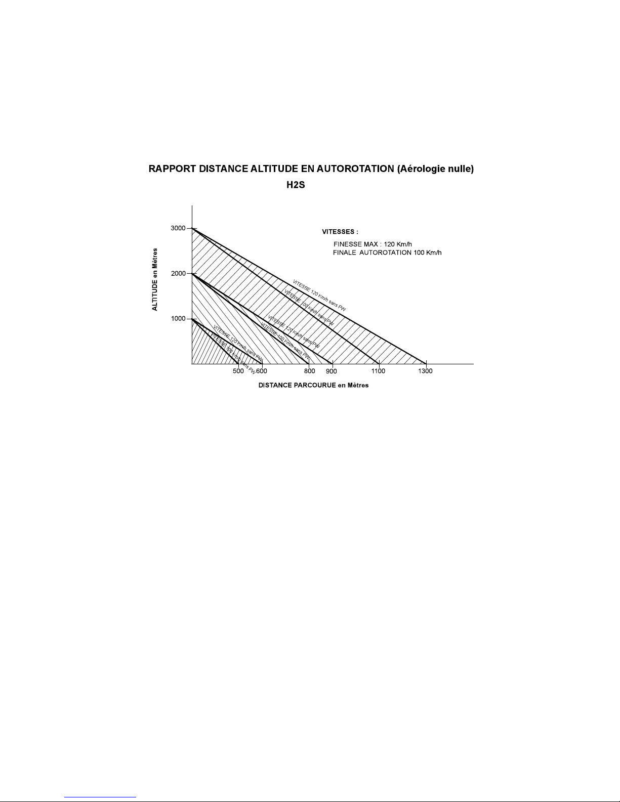
FLIGHT MANUAL DYNALI HELICOPTER COMPANY Edition N°3
DYNALI H2S January 2012
__________________________________________________________________________________
48
5.6. DISTANCE / ALTITUDE RATIO UNDER AUTO-ROTATION
This table has been established starting from hover outside ground effect
- at 1000 , 2000 and 3000 m at the FE local FE of Maubeuge (3280,65 and 9843 ft).
- wind not measured but very light ( below 5 kts)
Page 49
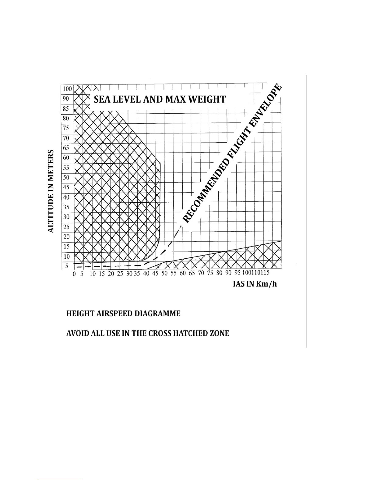
FLIGHT MANUAL DYNALI HELICOPTER COMPANY Edition N°3
DYNALI H2S January 2012
__________________________________________________________________________________
49
5.7. HEIGHT SPEED DIAGRAMME
Page 50

FLIGHT MANUAL DYNALI HELICOPTER COMPANY Edition N°3
DYNALI H2S January 2012
__________________________________________________________________________________
50
5.8. NOISE LEVEL
Noise levels, determined under conditions set by article 6 of the decree of 19 /02/ 1987
(chapter 8 and appendix 4 of the second part of appendix 16), are as follows :
Recording conditions:
(unobstructed zone, free, no background noise)
REFERENCE MEASUREMENT
POINTS
NOISE LEVELS
( EPNDB)
NOISE LIMITS
( EPNDB )
Takeoff
71
82
Approach
73
82
Overflight
69
82
Page 51

FLIGHT MANUAL DYNALI HELICOPTER COMPANY Edition N°3
DYNALI H2S January 2012
__________________________________________________________________________________
51
CHAPTER 6 – MASS AND BALANCE
6.1. GENERAL
6.2. MASS AND BALANCE
6.3. HELICOPTER LOADSHEET
6.4. LATERAL BALANCING
Page 52

FLIGHT MANUAL DYNALI HELICOPTER COMPANY Edition N°3
DYNALI H2S January 2012
__________________________________________________________________________________
52
6.1. GENERAL
The purpose of this chapter is to provide the information and the required elements to enable
the calculation of the mass and balancing of the H2S helicopter in service.
6.2. LONGITUDINAL BALANCING
WARNING
The field of balancing is conditional on the flight controls being well adjusted and with full free
movement. The original setting of the horizontal stabiliser must not be modified.
Longitudinal balance is limited between the two balancing extremities fore and aft which
correspond to the limits tested in flight.
Between these two extremities, fore and aft, anything is permitted as long as the maximum
takeoff weight of 700 kg is not exceeded.
EMPTY WEIGHT
Empty weight is the mass of a Dynali H2S helicopter empty but including :
− basic on-board equipment
− engine oil
− engine coolant
− the various lubricants
− the unusable quantity of fuel (2,5L)
The empty weight as well as the empty C.G. must be measured for each H2S helicopter
once assembly is complete. There will be slight differences in the empty weight as well as
the position of the C.G. from one helicopter to another.
STANDARD EMPTY WEIGHT
Empty weight of a helicopter of the type measured at the Dynali plant.
PAYLOAD
Difference between the maximum takeoff weight and the empty weight.
METHODS OF DETERMINING EMPTY WEIGHT
− Suspend the helicopter from a balance.
− Find a technical weighbridge for vehicles (in customs or in an industrial zone).
− Locate 4 sets of human scales 2 under each skid, on at 20 cm behind the axis of the wheel
attachment and one 26 cm forward. A delicate and imprecise operation.
Page 53

FLIGHT MANUAL DYNALI HELICOPTER COMPANY Edition N°3
DYNALI H2S January 2012
__________________________________________________________________________________
53
METHOD FOR DETERMINING THE EMPTY C.G.
− Roll the H2S onto a round bar under the skids
− The bar must be placed perpendicularly to the longitudinal axis
− Hold the helicopter with the mast vertical, in balance on the bar.
− A spirit level is placed on the receiving pulley, this being perpendicular to the mast.
− The virtual junction of the axis of the mast and the skids is 190mm forward of the axis of
the attachment of the rear wheel.
=> measure the distance between the bar and the axle of the rear wheels (Normally 75 mm).
A simple subtraction will permit the determination of the C.G. point: 190 mm – 75 mm = 115
mm = basis for the calculation.
Page 54

FLIGHT MANUAL DYNALI HELICOPTER COMPANY Edition N°3
DYNALI H2S January 2012
__________________________________________________________________________________
54
DATA
Maximum takeoff weight ....................................................................... 700 kg
Maximum landing weight......................................................................... 700 kg
Standard empty weight ........................................................................... 465 kg
Standard payload .................................................................................... 235 kg
Datum point ............................................... defined as the axis of the rotor mast
Forward balance limit, distance from datum ......................................... 122 mm
Aft balance limit, distance from datum ................................................... -34 mm
DETERMINATION OF LONGITUDINAL BALANCE
Each part of the helicopter is associated with a mass (weight) expressed in kg and in
moment in relation to the datum point expressed in kg*m. This moment corresponds to the
mass of the part multiplied by the distance from the C.G. of the part in relation to the datum.
Before each flight you must :
- Firstly determine the balance of your Dynali H2S. You should verify that the position of the
C.G. of your Dynali H2S, at the moment of takeoff, is within the fore and aft balance limits.
- You must also make sure that the takeoff weight of your Dynali H2S does not exceed the
authorised Maximum Takeoff Weight of 700 kg.
These two conditions are met if the point defined by the takeoff weight and the position of the
C.G. are within the area for longitudinal balancing (see illustration of longitudinal balance
area).
If either of these conditions is not met, you must cancel the flight. Either plan on takeoff with
a lighter load or with a different spread of the mass in the cabin, or both.
The table below summarises the weights, distance in relation to the datum point and the
moment associated with the elements of the helicopter and its payload.
Element
Mass/weight
[kg]
Distance % datum
[mm]
Moment
[kg.mm]
Standard empty weight
465
-115
-53475
Doors mounted
6
575
3450
Passenger
Mpax
575
Mpax x 575
Usable fuel
(0.7 kg/l)(max 85 l=60 kg)
Mfuel
175
Mc x 175
Baggage (max 26 kg)
Mbag 0 0
Page 55
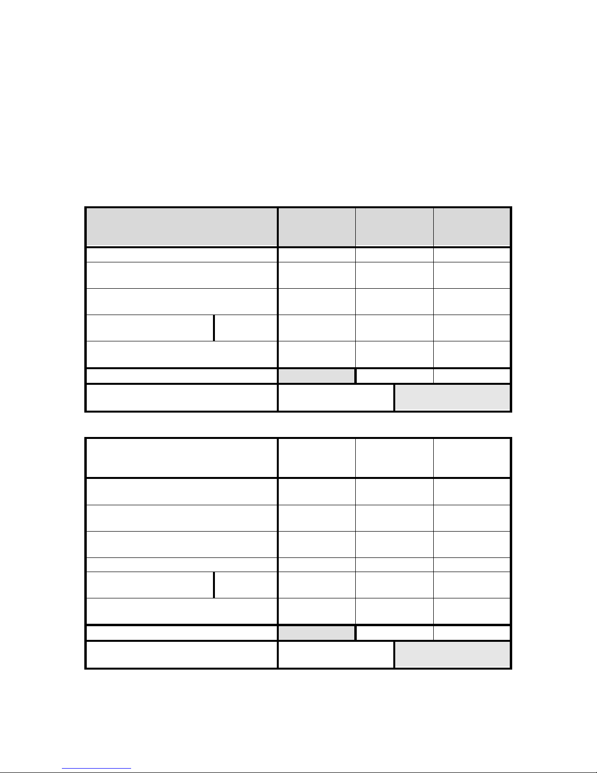
FLIGHT MANUAL DYNALI HELICOPTER COMPANY Edition N°3
DYNALI H2S January 2012
__________________________________________________________________________________
55
BALANCE LIMIT
Minimum mass of solo pilot 60 kg. Below this mass, when the fuel runs low, the limits of aft
balance may be exceeded. Below this mass, ballast must be added to maintain the
equivalent of 60 kg minimum on the passenger seat.
In hovering flight, at the limit of the aft balance, the Dynali H2S will be inclined 2° to the rear.
At the forward balance limit, the H2S will be inclined 3° forward.
Below are two examples of calculating balance. The points defined by these two examples
are reflected in the longitudinal balance graph.
Example 1 for balance calculation :
1 passenger, 27L of fuel, doors removed
Mass
[kg]
Distance %
datum
[mm]
Moment
[kg.mm]
Empty weight
465
-115
-53475
Left hand passenger
(!Put the heavier person on the left!)
83
575
47870
Right hand passenger
-
575
0
Usable fuel d
(0.7 kg/l)(max 90L=60 kg)
27L
19
175
3307,5
Baggage
(max 26 kg)
0 0 0
TOTAL
575
//////////////
-2300
CG for this configuration
-2300 / 575
-4 mm
Example 2 for balance calculation :
2 passengers, 55 litres of fuel, doors mounted
Mass
[kg]
Distance %
datum
[mm]
Moment
[kg.mm]
Empty weight
465
-115
-53475
Doors mounted (2 * 3 kg)
6
575
3450
Left hand passenger ( !Put the heavier
person on the left!)
85
575
48875
Passenger on the right
81
575
46575
Usable fuel
(0.7 kg/l)(max 85 l=60 kg)
55 litre
39
175
6825
Baggage
(max 26 kg)
0 0 0
TOTAL
676
//////////////
52250
CG for this configuration
52250 / 676
77 mm
Page 56
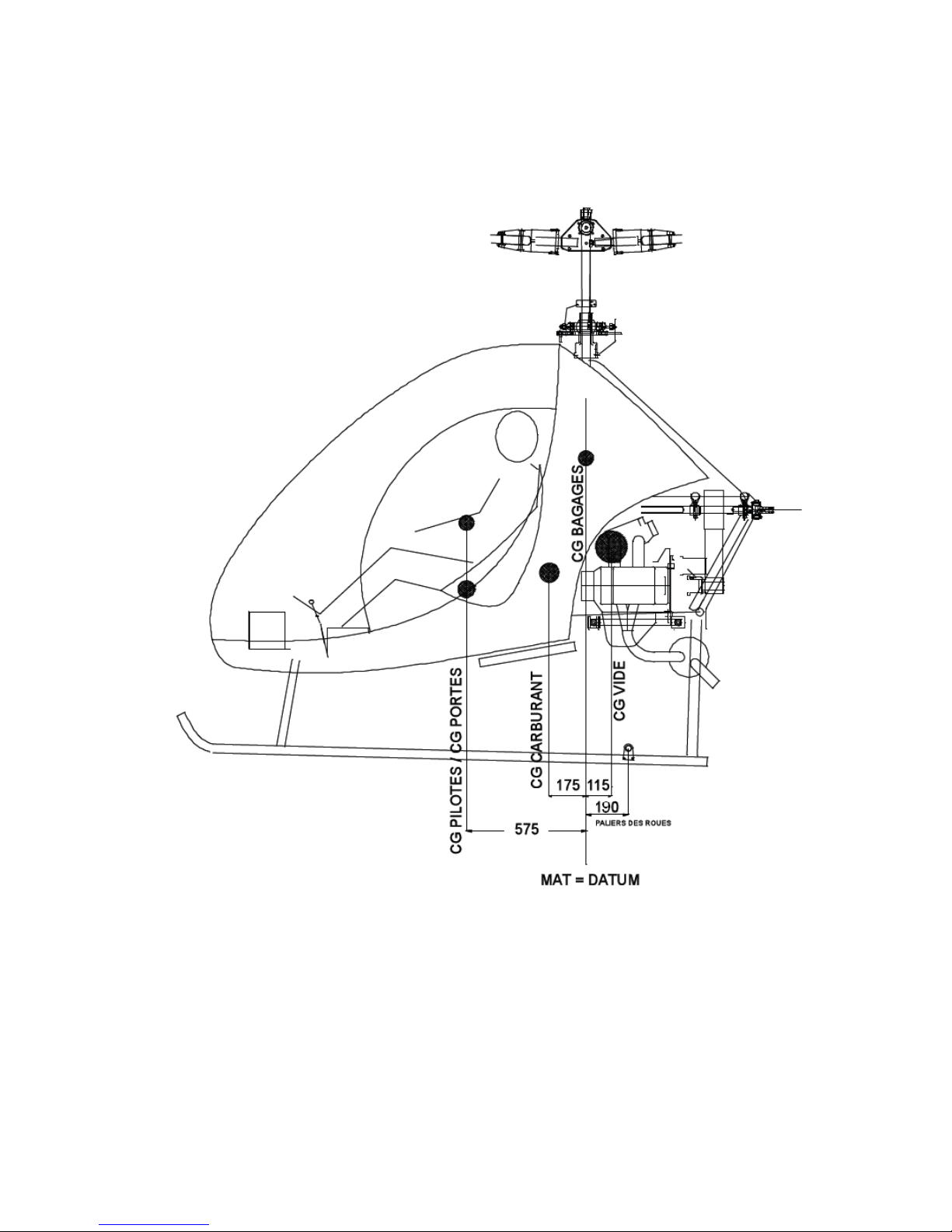
FLIGHT MANUAL DYNALI HELICOPTER COMPANY Edition N°3
DYNALI H2S January 2012
__________________________________________________________________________________
56
Position of the centres of gravity of the various parts of the H2S
Page 57
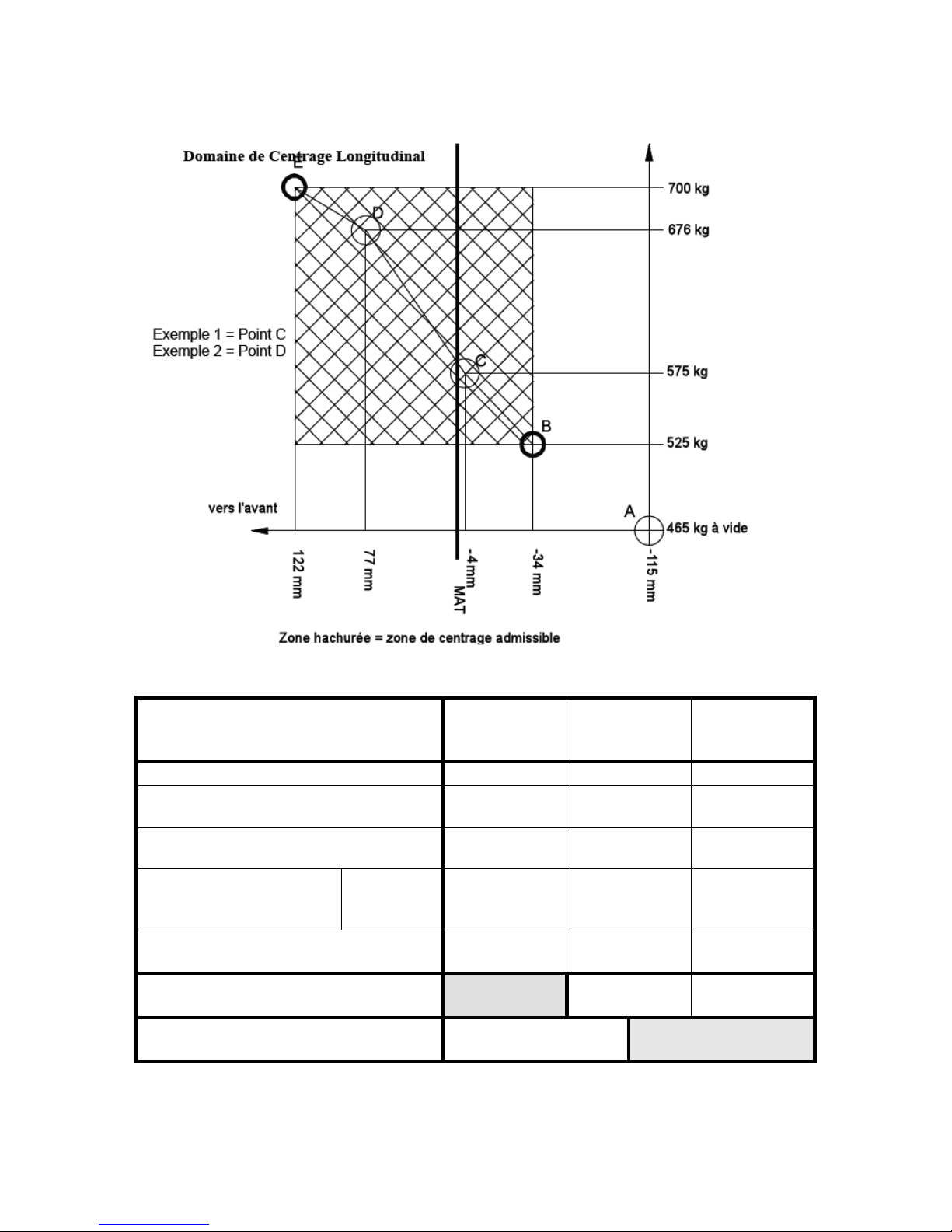
FLIGHT MANUAL DYNALI HELICOPTER COMPANY Edition N°3
DYNALI H2S January 2012
__________________________________________________________________________________
57
Calculation of balance for your H2S
Mass/weight
[kg]
Distance %
datum
[mm]
Moment
[kg.mm]
Empty weight*
Left hand passenger
( !Put the heavier person on the left!)
575
Right hand passenger
575
Usable fuel
(0.7 kg/l)(max 90L = 60
kg)
……..…L
175
Baggage
(max 26 kg)
0 0
TOTAL
//////////////
CG in this configuration
Mom Tot / Tot weight=
* If the doors are removed, subtract 6kg and 3450kg*mm.
Page 58

FLIGHT MANUAL DYNALI HELICOPTER COMPANY Edition N°3
DYNALI H2S January 2012
__________________________________________________________________________________
58
6.3. INDIVIDUAL WEIGHT SHEET
INDIVIDUAL WEIGHT SHEET (to be completed and retained in this manual) DYNALI H²S
DYNALI H2S
DATE
HULL SERIAL N° (s/n)
REGISTRATION
OWNER
NAME
ADDRESS
PLACE OF WEIGHING
TYPE OF WEITHING (specify : hoist + spring balance, other…)
WEIGHED EMPTY WEIGHT
The empty weight of a Dynali H2S helicopter empty but including
- basic on-board equipment
- the two doors (2 x 3 kg = 6 kg)
- full engine oil
- engine coolant
- the various lubricants
- the quantity of unusable fuel (2,5L)
kg
POSITION OF THE CG EMPTY % DATUM*
at ……….. mm forward of the wheel axles (190 mm - …...
mm)
= …......... mm rear of the axis of the rotor mast
*Datum = axis of the rotor mast
mm
NOTES
Empty C.G. measured at ………mm aft of the axis of the mast, i.e. forward, ** - exact** - aft**
of the standard Dynali H2S C.G. (located 115 mm aft of the mast axis)
* *delete where inapplicable
Page 59

FLIGHT MANUAL DYNALI HELICOPTER COMPANY Edition N°3
DYNALI H2S January 2012
__________________________________________________________________________________
59
6.4. LATERAL BALANCING
The Dynali H2S is equipped with dual controls. Except in solo flight when the pilot must be in
the left hand seat, the Dynali H2S can be piloted from either the left or the right hand seat. In
order to guarantee the airworthiness of the aircraft, the left hand side of the helicopter must
always be heavier than the right.
SOLO PILOT MUST BE IN LEFT SEAT
MINIMUM WEIGHT OF SOLO PILOT 60 KG
TWO MAN CREW
THE HEAVIER OF THE TWO MUST BE IN THE LEFT HAND
SEAT
SOLO PILOT (must be in left hand seat)
Minimum weight of solo pilot : 60 kg
Maximum weight of solo pilot without ballast in right hand seat : 110 kg
110kg on the left = limit of acceptable cyclic movement to the right to maintain operational
manoeuvrability.
Above 110 kg in the left hand seat, add ballast in the right hand seat corresponding to the
surplus weight of the pilot over and above 110 kg
Maximum weight of solo pilot: 135 kg
TWO MAN CREW
Place the heavier person in the left hand seat.
NB : The condition for balance to compensate for the thrust of the tail rotor is 13 kg more on
the left hand seat (**) so that the mast is vertical in hover. However the aircraft remains
completely manoeuvrable but with a list. See chapter 6, paragraph 6.4.
(**) This explains the need for solo pilots to use the left hand seat.
CARRIAGE OF BAGGAGE IN HOLDS
Spread the baggage so that the left hand side of the aircraft remains the heavier.
Page 60

FLIGHT MANUAL DYNALI HELICOPTER COMPANY Edition N°3
DYNALI H2S January 2012
__________________________________________________________________________________
60
CHAPTER 7 – SYSTEMS
7.1. GENERAL
7.2. CABIN SHELL
7.3. UNDERCARRIAGE
7.4. MAIN ROTOR
7.5. REAR TURBINE OR ANTI-TORQUE ROTOR
7.6. TRANSMISSIONS
7.7. ENGINE
7.8. FLIGHT CONTROLS
7.9. ENGINE – CLUTCH – DRIVE BELTS
7.10. FUEL CIRCUIT
Page 61

FLIGHT MANUAL DYNALI HELICOPTER COMPANY Edition N°3
DYNALI H2S January 2012
__________________________________________________________________________________
61
7.1. GENERAL
The goal of this chapter is to introduce to the pilot who has not assembled his helicopter, the
systems of the Dynali H2S. For further information, refer to the assembly manual. However,
we would advise the pilot to read the assembly manual.
7.2. CABIN SHELL
The Dynali H2S is a single engine two-seater helicopter with a single main rotor, of primarily
metallic construction and equipped with a skid type undercarriage. The highly resistant basic
structure or the cell is made of stainless steel tubes to provide passive safety to the crew.
A part of the tail tube and the strengthening stays are in aluminium. A carbon-kevlar fairing is
installed but is not structural.
The firewall is made of Kevlar and M2F2 fireproof resins
7.3. UNDERCARRIAGE
The undercarriage is made of aluminium tubes; it is of the energy absorbing type with two
legs on each side (passive safety)
7.4. MAIN ROTOR
- When still, the blade roots withdraw in their bearings on their spindles to the limit. The
overhanging mass of the blades creates a high level of force on the blade roots.
- The blades are made of composite materials (glass fibre / carbon / aeronautical resin).
- The blades are held by aluminium roots, which incorporate a system for adjusting the
alignment.
- Four stop bearings with oblique contact allow for the varied incidence of the blade when
pitch adjusted.
- The two flanges swing over around the head of the mast on combined bearings.
- The rotor head is of the swing-over type without flapping.
7.5. REAR TURBINE OR ANTI-TORQUE ROTOR
- The anti-torque rotor has eight blades. It enables for a small diameter which increase
safety.
- The eight blades are made in composite carbon/kevlar, held in split blade sockets.
- The blade sockets are held in smooth plates of Teflon.
- The anti-torque rotor is protected by a tail surround made of carbon.
- The entire construction is designed to provide full protection for the anti-torque rotor.
Page 62

FLIGHT MANUAL DYNALI HELICOPTER COMPANY Edition N°3
DYNALI H2S January 2012
__________________________________________________________________________________
62
7.6. TRANSMISSIONS
- A small driving pulley is bolted directly onto the shaft emerging from the clutch shaft. Eight
trapezoid belts transmit the movement of the main pulley to the upper pulley which contains
the two free wheels. The shaft transmits the movement towards the front of the main rotor
via the main transmission box and towards the tail rotor via a flexible joint then to the rear
transmission box.
- The long transmission shaft for the rear rotor is supported by bearings in the tail tube.
- The main transmission box includes conic gearing with helicoidal cogs providing a single
reduction stage, lubricated by an oil bath. It is cooled by the circulation of the oil and by an
air vent.
- The rear transmission box also contains a pair of conic gears with helicoid gears lubricated
by an oil bath. The inward and outward shafts are made of stainless steel.
« HIGH » OIL LEVELS IN THE MAIN TRANSMISSION AND OF THE TAIL ROTOR
GEARING ARE EXTREMELY IMPORTANT ; MAINTENANCE OF THIS HIGH LEVEL IS
DESIGNED TO AVOID CAVITATION.
7.7. ENGINE
Subaru DS EJ25 engine
Stroke : 2500 cm
3
Power : 180HP
Motor structure : Subaru
Electronic injection : MOTEC
Exhaust : Dynali
7.8. FLIGHT CONTROLS
Standard equipment includes dual controls. The cyclic on the passenger side can be
removed. All controls are activated via shafts with maintenance free ball joint ends. The
flight controls of the Dynali H2S operate in the same way as the controls of most other
helicopters. The cyclic and the collective control the pitch of each blade via a cyclic teetering
hinge.
The cyclic stick is double but the two elements can be separated. The regulations only allow
dual control during pilot training with an instructor.
The collective is also of the classical type with a twisting throttle grip. An electronic system
controls the fuel supply as a function of the collective but fine adjustment is still necessary
and is supplied by a servo called the governor. The governor acts on the air intake valve of
the injection system. It is commanded by the computer.
The friction of the collective is adjusted by the torque tightening of its attaching bolt.
It is possible to take off with a failed governor but the pilot must then adjust the throttle grip to
maintain 100% on the rev. counter until landing)
Page 63

FLIGHT MANUAL DYNALI HELICOPTER COMPANY Edition N°3
DYNALI H2S January 2012
__________________________________________________________________________________
63
The pedals operate the pitch control for the blades of the tail rotor through two teleflex
cables.
Note : the control cables are not submitted to any special strain, a system of contra-rotating
pinions neutralises the thrust efforts.
7.9. ENGINE - CLUTCH - DRIVE BELTS
The H2S has an automatic centrifugal clutch. The drive belt tension is regulated by a floating
tension spring.
In the receiving pulley there are two free wheels.
7.10. FUEL CIRCUIT
The fuel is supplied to the injection system by two electric pumps.
Page 64

FLIGHT MANUAL DYNALI HELICOPTER COMPANY Edition N°3
DYNALI H2S January 2012
__________________________________________________________________________________
64
CHAPTER 8 – HANDLING AND MAINTENANCE
8.1. GENERAL
8.2. REQUIRED DOCUMENTS
8.3. MAINTENANCE
8.4. MODIFICATIONS TO THE HELICOPTER
8.5. MANŒUVRES ON THE GROUND
8.6. PARKING AND TIEING DOWN
8.7. MAINTENANCE AND PROCEDURES
8.8. MAINTENANCE AND SERVICE LIFE
Page 65

FLIGHT MANUAL DYNALI HELICOPTER COMPANY Edition N°3
DYNALI H2S January 2012
__________________________________________________________________________________
65
8.1. GENERAL
This chapter describes the recommended procedures for the handling and maintenance of
the Dynali H2S helicopter.
Any person designated by the assembler of the kit or the new owner is authorised to
undertake this maintenance, under the responsibility of the owner.
We ask that each new owner makes himself known to, and remains in close contact (via the
Internet) with the Dynali Helicopter Company in order to receive regular updates concerning
the Dynali H2S.
In the event of the sale of his helicopter the original assembler passes the manuals to the
buyer and asks him to make contact with Dynali.
Additionally the Internet site displays new information of interest to all. The e-mail address
is :
www.dynali.com
The official regulations stipulate that the responsibility and the maintenance of a helicopter
sold in kit form lies exclusively with assembler-owner-operator of this helicopter. He must
ensure that all maintenance is performed in compliance with the maintenance manual.
All limitations, procedures, safety procedures, service lifetimes and maintenance conditions
set out in the present manual are considered as imperative.
8.2. OBLIGATORY DOCUMENTS
The following documents must be maintained permanently on board the aircraft :
1. Restricted airworthiness certificate
2. Identification certificate
3. Radio operation certificate (if the helicopter is equipped with a radio transmitter)
4. Flight manual in English
5. Log book
6. Civil responsibility insurance
8.3. MAINTENANCE
All work must be noted in the appropriate log book supplied by Dynali with the document set.
-Date on which the work has been performed.
-Number of hours flight.
-Description of the work and any comments
-Contact by telephone with Dynali is always possible, if any doubt arises..
Page 66

FLIGHT MANUAL DYNALI HELICOPTER COMPANY Edition N°3
DYNALI H2S January 2012
__________________________________________________________________________________
66
8.4. MODIFICATIONS TO THE AIRCRAFT
PROTOCOL OF AGREEMENT FOR A MODIFICATION TO A DYNALI H2S
By these presents it is understood and defined as follows :
The assembler of the kit (or client)
I, the undersigned,…………………………. Undertake to inform Dynali Helicopter Company of
any modification that I wish to perform…………………………….. on my Dynali H2S kit.
Procedure to follow for the modification of a kit.
If a client wishes to modify his kit, he must show that he has established the appropriate
contacts with Dynali Helicopter Company to be able to declare to the ministry of civil aviation
that the aircraft, as modified, still complies with the conditions of airworthiness notified by the
ministry when the kit was declared to be eligible.
Dynali Helicopter Company declines all responsibility for any modification of the kit
undertaken outside the above framework.
8.5. MANEUVRES ON THE GROUND
- PRECAUTION : climbing onto the undercarriage and step onto any part of the structure in
stainless steel to examine the rotor :
- On skids, the helicopter is manoeuvred on the ground on its retractable wheels.
- Manœuvre using the tail = better hold = better overall view.
8.6. PARKING AND TIEING DOWN
-Always align the blades in the longitudinal axis of the aircraft.
-The slightest wind will cause the rotor blades to flap. Always use a strap to attach the rear
blade to the tail tube. Ideally two straps will retain the blade perfectly and avoid the risk of
strong gusts putting the whole aircraft in danger.
-In stormy weather or when the wind is very strong, the helicopter should be placed in a
hangar or evacuated to a safe place.
8.7. MAINTENANCE AND PROCEDURES
(Please refer to the maintenance manual ref : DYNH2S/01/01/T04)
8.8. MAINTENANCE AND SERVICE LIFE
PARTS WITH LIMITED SERVICE LIFE
(Please refer to the maintenance manual ref : DYNH2S/01/01/T04)
 Loading...