

Page 1
Version 1.1
Shaker Incubator
Instructions for use
Manuel d’utilisation
Istruzioni per l’uso
Instrucciones de funcionamiento
Bedienungsanweisung
SI50 SI70 SI80
Page 2
English
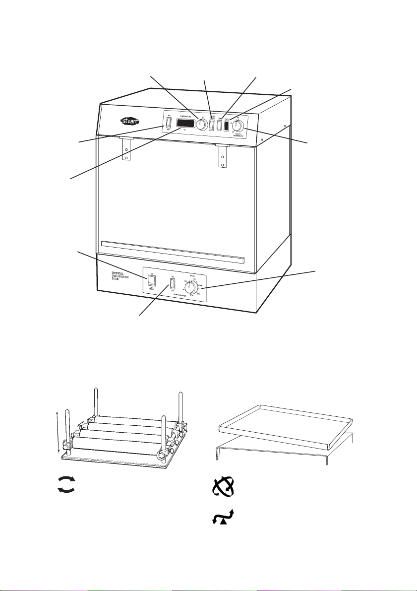
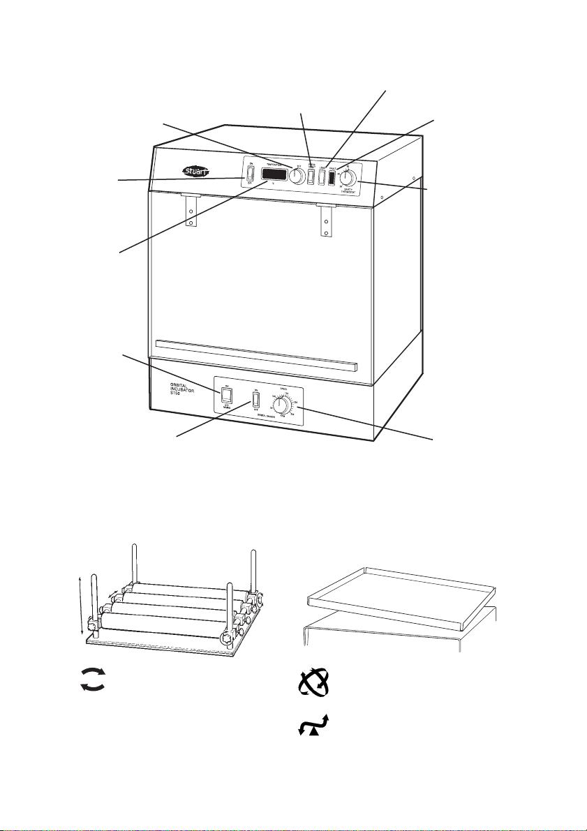
Fig 1 Shaker Incubator controls
Fig 2 Platforms and shaking actions
SI50: Orbital shaker
(includes cradle system with
four securing bars)
SI70: Gyratory rocker
(includes blue non-slip mat
and tier system)
SI80: See-saw rocker
(includes blue non-slip mat
and tier system)
Heater
On/Off
LCD
Set Switch Load indicator
Fault indicator
Over temperature
Temperature control
Mains
On/Off
Motor On/Off
Speed
Controller
Page 3

Thank you for purchasing this Barloworld
Scientific product. To get the best
performance from the equipment, and for
your personal safety, please read these
instructions carefully before use.
This equipment is designed to operate under the
following conditions:-
❖ For indoor use only
❖ Use in a well ventilated area
❖ Ambient temperature range +5°C to +40°C
❖ Altitude to 2000m
❖ Relative humidity not exceeding 80%
❖ Mains supply fluctuations not exceeding 10%
❖ Overvoltage category II IEC60364-4-443
❖ Pollution degree 2 IEC664
If the equipment is not used in the manner
described in this manual the protection provided
by the equipment may be impaired.
Electrical installation
THIS EQUIPMENT MUST BE EARTHED
Before connection please ensure that the
line supply corresponds to that stated on the
rating label.
Power requirements all models:
Voltage & Wattage
230V, 50Hz,~ , 350W
There is an IEC socket at the rear of the
instrument for connection to the mains supply.
The unit is supplied with two mains leads fitted
with IEC plugs for connection to the instrument.
One has a U.K. 3 pin plug and the other has a 2
pin “Shuko” plug for connection to the mains.
Choose the lead appropriate for your electrical
installation and discard the other.
Should neither lead be suitable, take the lead
with the U.K. plug and replace the plug with a
suitable alternative. See the enclosed instruction
sheet for advice on how to carry out this
procedure.
Should the mains lead require replacement a
cable of 1mm
2
of harmonised code H05W-F
connected to an IEC 320 plug should be used.
1
IF IN DOUBT CONSULT A QUALIFIED
ELECTRICIAN
The mains lead should be connected to the
instrument BEFORE connection to the mains
supply.
Safety Advice Before Use
❖ Never move or carry the unit when in use or
connected to the mains electricity supply.
❖ Do not mix flammable liquids or use the
equipment in hazardous atmospheres.
❖ In the case of mains interrupting, a fault or
mechanical failure, the unit will continue to
operate on removal of fault.
❖ Mechanical energy can lead to breakage of
glass vessels. Use with care.
General description
CAUTION: Keep fingers clear when
operating door.
This range of Stuart incubators contains three
models each fitted with a moving platform
offering a choice of shaking action.
SI50: Has an orbital shaker with variable speed
between 20 and 250rpm and an orbit of 16mm.
The shaker platform is fitted with an robust mat
and adjustable rubber coated bars to secure the
load.
SI70: Has a 3D gyratory rocker with variable
speed between 10 and 70rpm and an angle of
tilt adjustable from 3-12°. The shaker platform is
fitted with an anti-slip mat.
SI80: Has a simple side to side rocking platform
with variable speed between 10 and 70rpm and
an amplitude adjustable from 1-7°. The shaker
platform is fitted with an anti-slip mat.
The incubator compartment is heated by an
efficient sheathed element. Forced air circulation
and precise digital control gives accurate heat
distribution and a quick response to set
temperatures. For visibility of the contents the
walls of the incubator are made from smoked
acrylic.
Page 4

2
The moving platform is operated by a geared
induction motor. The speed is modulated by a
soft start feedback controller in order to avoid
splashing on start up and maintain long-term
stability of set speed.
SI70 and SI80 are supplied with 2 extra platforms
that may be mounted in a tier to increase
capacity.
The doors of all models are fitted with a safety
interlock device to prevent the platform moving if
the door is open.
Operation (see fig. 1 & 2 for controls)
Position the apparatus on a firm level surface
ensuring there is sufficient room to open the
door outward.
Ensure the temperature and speed control knobs
are fully to the left and switch the mains, motor
and heater ON as required.
Temperature Selection - all models
Depress and hold the press to set switch and turn
the temperature control knob until the required
temperature appears on the display. On releasing
the switch, the display will revert to the actual
temperature of the incubator. The load indicator
will remain lit until the desired temperature
setting is reached at which time it will flash to
show that the temperature is being controlled.
Once the temperature has been set, turn the over
temperature control knob to approximately 20°C
above the set temperature.
Platform operation - SI50
Secure the vessels to be shaken between the
rubber coated bars. Ensure the door is fully
closed and then turn the speed controller to the
right until the required shaking speed is observed.
Platform operation - SI70 and SI80
Place the vessels to be shaken on the platform
with the load distributed as evenly as possible.
Ensure the door is fully closed and then turn the
speed controller to the right until the required
shaking speed is observed.
Installing the tier system - SI70 and SI80
SI70 and SI80 are supplied with 2 extra platforms
tiers which may be used to increase capacity. The
units are supplied with 4 long magnetic support
legs and 8 shorter magnetic support legs to allow
a choice of spacing between the platforms. Also
both platforms may be fitted at the same time if
the shorter legs are used.
To fit the accessory platform, first screw a
magnetic leg onto the captive thread in each
corner.
Ensure that the motor is turned off. The
accessory platform can then simply be placed on
top of the main platform and will be held in
place by the magnetic legs. The second accessory
platform can then be similarly located on top of
the first. To remove for cleaning etc., simply lift
the platform, separating the magnetic legs from
the supporting platform below.
Adjustment of Tilt Angle - SI70
1. Switch motor off.
2. Remove anti-slip mat from the platform and
switch the motor back on and adjust the
motion to a slow speed. Observe the two
apertures at the centre of the platform,
during rotation two adjusting screws will
come into view. When they are aligned
switch the motor off.
3. There are 2 locking screws located under the
platform on the drive boss, facing front on.
Check that these are accessible and, if not,
switch the motor back on and allow the unit
to rotate 180° and switch off when the
adjustment screws are aligned again.
4. Unlock the 2 locking screws positioned on
the drive boss using the extended wrench
provided. The tilt angle can now be adjusted
Page 5

3
using the short hex wrench. Release the
adjusting screws and adjust until the desired
angle is obtained and then lock off the
adjusting screws. Lock off the locking screws
on the drive boss.
5. Switch the motor back on and check
operation.
Adjustment of Tilt Angle - SI80
1. Position the unit with its left side facing
forward.
2. Remove the white plastic cap located in the
centre at the bottom of the unit.
NOTE: The mains power needs to be
connected during adjustment so care
must be taken not to touch anything but
the parts in the instruction below. All the
live electrical parts are mounted on the
front panel so are well away from the
area of concern.
3. Turn the speed control to its slowest setting
and, looking through the hole, watch for the
black Allen screw to come into view. Stop the
motor when it is directly facing you.
4. Using the tool provide with the rocker,
unscrew the Allen screw by two
turns.Remove the tool and rotate the motor
by 180° and stop it when the silver headed
slot screw is directly facing you.
5. Turn the screw clockwise until tight. This
method increases tilt. Continue the above
until the desired tilt is achieved.
6. To reduce the tilt, turn the screws in the
opposite direction in the opposite sequence,
i.e. undo the slot headed screw & tighten the
Allen screw.
Maintenance & Servicing
WARNING: Ensure the unit is disconnected
from the mains electricity supply before
attempting maintenance or servicing.
Periodically clean the instrument using a damp
cloth and mild detergent solution. Do not use
harsh or abrasive cleaning agents.
Any repairs or replacement of parts MUST be
undertaken by suitably qualified personnel.
The following spares and accessories are available
from your laboratory dealer.
Description Cat
Number
Spare securing bar (SI50) RSI50
Blue Dyson non-slip mat (SI70 & 80) KS0305
Spare platform tier (SI70 & 80) SI700090
For a comprehensive list of parts required by
service engineers conducting internal repairs and
a service manual, please contact the Technical
Service Department of Barloworld Scientific Ltd.
quoting both the model and serial number.
Only spare parts supplied or specified by
Barloworld Scientific Ltd. or its agents should be
used. Fitting of non-approved parts may affect
the performance and safety features designed
into the instrument.
If in any doubt, please contact the Technical
Service Department of Barloworld Scientific Ltd.
or the point of sale.
Barloworld Scientific Ltd.
Stone, Staffordshire ST15 0SA
United Kingdom
Tel: +44 (0) 1785 812121
Fax: +44 (0) 1785 813748
e-mail equipment@barloworld-scientific.com
www.barloworld-scientific.com
Page 6

4
Warranty
Barloworld Scientific Ltd warrants this instrument
to be free from defects in material and
workmanship, when used under normal
laboratory conditions, for a period of two (2)
years. In the event of a justified claim Barloworld
Scientific will replace any defective component or
replace the unit free of charge.
This warranty does NOT apply if damage is
caused by fire, accident, misuse, neglect,
incorrect adjustment or repair, damage caused by
incorrect installation, adaptation, modification,
fitting of non approved parts or repair by
unauthorised personnel.
Technical Specification (all models)
Temperature range Ambient + 5° to 60°C
Temp. display resolution 0.1°C
Temperature accuracy ±0.5°C
Overall dimensions (wxdxh) 450 x 436 x 606mm
Internal height 321mm
Electrical supply 230V, 50Hz, 350W
Page 7
Français
Fig 1 Incubateur avec Agitateur
Fig 2 Supports et mouvements d’agitation
SI50: Mouvement orbital
(avec plateau support, 4
barres de maintien)
SI70: Mouvement giratoire
(avec plateau anti-dérapant et
cadre pour étage supplémentair)
SI80: Mouvement de bascule
(avec plateau anti-dérapant et
cadre pour étage supplémentair)
Radiateur
Marche/
Arrêt
L.C.D
numérique
Commutateur de réglage
Indicateur de charge
Indicateur de
défaut
Surpassement
temp.
Régulateur de
température
Mise
sous/hors
tension
Moteur Marche/Arrêt
Régulateur
de vitesse
5
Page 8

Merci d’acheter ce produit de Barloworld
Scientific. Pour obtenir le bon
fonctionnement de l’équipement, et pour
votre sécurité, lire avec attention les
instructions ci-dessous avant l’utilisation.
Le matériel Barloworld Scientific est conçu pour
fonctionner dans les conditions suivantes.
❖ Pour l’usage en intérieur seulement
❖ Utilisation dans une pièce bien aérée
❖ Température ambiante +5°C à +40°C
❖ Altitude inférieure à 2000m
❖ Humidité relative n’excédant pas 80%
❖ Fluctuations de l’alimentation électrique
n’excédant pas 10% de la valeur nominale
❖ Catégorie II IEC60364-4-443 de surtension
❖ Degré 2 IEC664 de pollution
❖ Utilisation à une distance minimum de 200mm
autour des murs ou d’autres appareils
Si l’équipement n’est pas utilisé de la façon
décrite dans ce manuel les différentes fonctions
de l’appareil peuvent être altérées.
Installation Électrique
CET ÉQUIPEMENT DOIT ÊTRE RELIE À
LA TERRE
Avant le raccordement, s’assurer que
l’alimentation électrique convient. Cet
appareil exige une alimentation 230V, 50Hz,
monophasé. Une embase CEE est située à
l’arrière de l’instrument pour le raccordement à
l’alimentation électrique, (voir le schéma 1).
L’instrument est fourni avec deux câbles secteur
équipés d’une prises CEE pour le raccordement à
l’instrument. Sur un, se trouve une prise aux
normes anglaises et sur l’autre une prise de
européen 2P+T. Choisir le câble approprié pour
votre installation électrique et jeter l’autre.
Si ni l’un ni l’autre ne conviennent, vous devrez
alors obtenir le bon câble localement. Si ce n’est
pas possible, prendre celui avec la prise anglaise,
la couper et la remplacer par celle
correspondante au pays d’utilisation. Voir la
feuille d’instruction incluse pour le montage de
cette prise.
6
Si l’état du câble secteur exige son remplacement
un câble de 1mm
2
norme H05W-F relié à une
prise CEE 320 devra être employé.
Le câble doit être relié à l’instrument AVANT le
raccordement à l’alimentation électrique.
EN CAS DE DOUTE CONSULTER UN
ÉLECTRICIEN QUALIFIÉ
Consignes de sécurité avant utilisation
❖ Ne jamais déplacer ou transporter l’appareil
quand il est en service ou branché sur secteur.
❖ Ne pas mélanger des liquides inflammable ni
utiliser l’équipement dans des atmosphères
dangereuses.
❖ En cas de coupure électrique, de défaut ou de
défaillance mécanique, l’unité continue de
fonctionner après suppression du défaut.
❖ L’énergie mécanique peut briser les récipients
ne verre. Utiliser avec prudence.
Description générale
AVERTISSEMENT : Eloignez vos doigts à
l’ouverture ou à la fermeture de la porte.
Cette gamme d’incubateurs Stuart comprend
trois modèles, chacun étant équipé d’une
plateforme mobile pour offrir un choix varié
d’agitations.
SI50 : Présente un agitateur orbital à vitesse
variable entre 20 et 250 tr/min et un orbite de 16
mm. La plateforme de l’agitateur est équipée
d’un tapis robuste et de barres à revêtement de
caoutchouc pour protéger la charge.
SI70 : Présente un basculeur giratoire 3D à
vitesse variable entre 10 et 70 tr/min et un angle
d’inclinaison de 3 à 12°. La plateforme de
l’agitateur est équipée d’un tapis antidérapant.
SI80 : Présente une plateforme simple à
basculement latéral à vitesse variable entre 10 et
70 tr/min et une amplitude réglable de 1 à 7°. La
plateforme de l’agitateur est équipée d’un tapis
antidérapant.
Le compartiment de l’incubateur est chauffé par
un élément blindé performant. Une circulation
d’air forcé et un contrôle numérique précis
Page 9

7
fournissent une distribution de chaleur précise et
une réponse rapide aux températures de
consigne. Les parois de l’incubateur sont en
acrylique fumée pour voir le contenu.
La plateforme mobile est commandée par un
moteur asynchrone à engrenage. La vitesse est
modulée par un régulateur à rétroaction à
démarrage doux afin d’éviter les projections au
démarrage et de maintenir une stabilité à long
terme de la vitesse spécifiée.
Les modèles SI70 et SI80 sont fournis avec 2
plateformes supplémentaires pouvant être
montées en étage pour augmenter la capacité.
Tous les modèles ont des portes équipées d’un
dispositif de verrouillage de sécurité pour éviter le
déplacement de la plateforme si la porte est
ouverte.
Fonctionnement
(voir Schémas 1 et 2 pour les commandes)
Positionnez l’appareil sur une surface plate et
ferme en veillant à avoir suffisamment d’espace
pour ouvrir la porte vers l’extérieur.
Vérifiez que les boutons des régulateurs de
température et de vitesse sont en position
maximale sur la gauche. Mettez l’appareil SOUS
tension, le moteur et le chauffage en MARCHE,
comme requis.
Sélection de la température - tous les
modèles
Appuyez et maintenez en appui le commutateur
de réglage et tournez le bouton du régulateur de
la température jusqu’à ce que la température
requise soit affichée. Au relâchement du
commutateur, l’affichage revient sur la
température réelle de l’incubateur. L’indicateur de
charge reste allumé jusqu’à ce que la
température recherchée soit atteinte puis clignote
pour indiquer que la température est régulée.
Lorsque la température est réglée, positionnez le
bouton du régulateur de surpassement de
température à env. 20°c au-dessus de la
température de consigne.
Fonctionnement de la plateforme - SI50
Immobilisez les récipients à agiter entre les barres
à revêtement de caoutchouc. Vérifiez que la
porte est complètement fermée puis tournez le
régulateur de vitesse sur la droite jusqu’à ce que
la vitesse d’agitation requise soit atteinte.
Fonctionnement de la plateforme S170 et S180
Placez les récipients à agiter sur la plateforme en
répartissant la charge aussi uniformément que
possible. Vérifiez que la porte est complètement
fermée puis tournez le régulateur de vitesse sur la
droite jusqu’à ce que la vitesse d’agitation requise
soit atteinte.
Installation du système à étage - SI70 et SI80
Les modèles SI70 et SI80 sont fournis avec 2
plateformes supplémentaires pouvant être
utilisées en étage pour augmenter la capacité. Les
unités sont fournies avec 4 pieds magnétiques
longs et 8 pieds magnétiques courts pour
permettre plusieurs choix d’espacement entre les
plateformes. En outre, les deux plateformes
peuvent être installées simultanément lorsque les
pieds courts sont utilisés.
Pour installer la plateforme supplémentaire, vissez
d’abord un pied magnétique dans la vis
imperdable de chaque angle. Vérifiez que le
moteur est sur la position Arrêt. La plateforme
supplémentaire peut alors être posée simplement
au-dessus de la plateforme principale et elle est
maintenue en position par les pieds magnétiques.
La deuxième plateforme supplémentaire peut
alors être installée de manière similaire au-dessus
de la première plateforme. Pour retirer la
plateforme (opérations de nettoyage, etc.), il
suffit de la soulever pour séparer les pieds
magnétiques de la plateforme inférieure qui la
supporte.
Réglage de l’angle d’inclinaison - SI70
1. Arrêtez le moteur. Retirez le tapis
antidérapant de la plateforme et fermez la
porte.
2. Remettez le moteur en marche et réglez le
mouvement sur une vitesse lente. Observez
les deux ouvertures au centre de la
Page 10

8
plateforme; deux vis de réglage deviennent
visibles pendant la rotation. Lorsqu’elles sont
alignées, arrêtez le moteur.
3. A l’aide de la clé hexagonale fournie,
desserrez les deux vis et réglez la plateforme
sur l’angle requis. Serrez les deux vis en
maintenant la plateforme à la position
requise.
Remarque : IL est plus facile de maintenir la
plateforme en position en vissant d’abord la
vis située sur le côté haut de la plateforme.
4. Fermez la porte, remettez le moteur en
marche et vérifiez le fonctionnement.
Réglage de l’angle d’inclinaison - SI80
1. Positionnez l’unité, côté gauche vers l’avant.
2. Retirez le cache en plastique blanc situé au
centre, au bas de l’unité.
REMARQUE : L’appareil doit être sous tension
lors du réglage. Il est donc important de ne pas
toucher d’autres éléments que ceux indiqués
dans les instructions ci-dessous. Tous les éléments
électriques alimentés sont montés sur le panneau
avant et sont donc éloignés de la zone
concernée.
3. Tournez le régulateur de vitesse sur le réglage
le plus bas et, en regardant par le trou,
attendez que la vis creuse soit visible. Arrêtez
le moteur lorsque elle est directement face à
vous.
4. A l’aide de l’outil fourni avec le basculeur,
desserrez la vis creuse de deux rotations.
Retirez l’outil et effectuez une rotation du
moteur à 180°C en vous arrêtant lorsque la
vis à fente à tête argentée est directement
face à vous.
5. Serrez fermement la vis dans le sens des
aiguilles d’une montre. Cette méthode
permet d’augmenter l’inclinaison. Continuez
jusqu’à ce que l’inclinaison recherchée soit
atteinte.
6. Pour réduire l’inclinaison, tournez les vis dans
la direction et l’ordre opposés (desserrez la vis
à fente à tête argentée et serrez la vis creuse).
Entretien et maintenance
ATTENTION ! Vérifier que l’appareil est
déconnecté de son alimentation
électrique, avant toute opération de
maintenance ou d’entretien.
Les surfaces de l’appareil et les accessoires
peuvent être nettoyés à l’aide d’un linge doux et
humide et un détergent approprié.
La lentille peut être démontée de son support
pour le nettoyage. Pour retirer la fenêtre de
protection du bloc chauffant, glisser le clip de
retenue avec de fine pinces et nettoyer avec un
chiffon très doux.
Description Numéro de
catalogue
Barre de sécurité de rechange
(SI50) RSI50
Tapis antidérapant Dyson bleu
(SI70 et 80) KS0305
Etage de plateforme de rechange
(SI70 et 80) SI700090
Pour une liste complète de pièces et un manuel
d’entretien technique, requis par des techniciens,
conduisant des réparations internes, entrer en
contact avec le service après vente technique de
Barloworld Scientific France en précisant le
modèle et le numéro de série.
Seules les pièces de rechange fournies ou
indiquées par Barloworld Scientific France ou ses
revendeurs doivent être employées. L’utilisation
de pièces non-approuvés peut affecter le
fonctionnement et la sécurité de l’instrument.
En cas de doute, contacter avec le service
technique de Barloworld Scientific France ou
votre revendeur.
Tél. : 01.64.45.13.13, fax : 01.64.45.13.00,
e-mail : bibby@bibby-sterilin.fr
Page 11

9
Garantie
Barloworld Scientific France garantit cet
appareil de tout défaut de fabrication ou de
montage pour une utilisation normale en
laboratoire et ce durant deux (2) ans. En cas
de défaillance, Barloworld Scientific France
s’engage à remplacer gratuitement la pièce
défectueuse ou l’appareil si ce dernier était
déclaré irréparable.
Cette garantie ne s’applique pas si les
dommages sont dus à un incendie, un
accident, une inondation, une négligence ou
une utilisation inadéquate. La garantie ne
s’applique pas non plus si l’appareil n’a pas
été installé correctement, réparé par une
personne non qualifiée ou modifié à l’aide de
pièces détachées ne provenant pas de la
société Barloworld Scientific France.
Cette garantie ne modifie pas les statuts et
droits des échanges commerciaux.
Barloworld Scientific France
Z.I. du rocher Vert – rue G. Eiffel
BP79
77793 NEMOURS cedex
Tél. : 01.64.45.13.13
fax : 01.64.45.13.00
e-mail : bibby@bibby-sterilin.fr
Spécification technique (tous les modèles)
Domaine de températures Ambiante + 5° à 60°C
Résolution d’affichage temp. 0,1°C
Précision des températures ±0,5°C
Dimensions hors-tout (wxdxh) 450 x 436 x 606mm
Hauteur interne 321mm
Alimentation électrique 230V, 50Hz, 350W
Page 12

10
Italiano
Fig. 1: Controlli incubatrice vibratrice
Fig. 2: Piattaforme e azioni di vibrazione
SI50: Vibratore orbitale
(Comprende sistema di
sostegno con quattro barre di
sicurezza)
Riscaldatore
On/Off
LCD
Digitale
Interruttore di regolamento
Indice carico
Indice difetto
Temp superiore
Controllo della
temperatura
Alimentazione
On/Off
Motore On/Off
Controllo
velocità
SI70: Appoggio rotativo
(Comprende tappetino blu antiscivolo
e sistema di sovrapposizione)
SI80: Appoggio ad altalena
(Comprende tappetino blu antiscivolo
e sistema di sovrapposizione)
Page 13

adatto al caso. Vedere la scheda di istruzioni
inclusa che contiene consigli sulle modalità per
effettuare tale sostituzione.
Se occorre sostituire il cavo da rete, occorre
impiegare un cavo di sezione 1mm
2
di codice
H05W-F armonizzato connesso ad una spina CEI
320.
IN CASO DI DUBBIO CONSULTARE UN
ELETTRICISTA QUALIFICATO
Si deve connettere il cavo da rete allo strumento
PRIMA di eseguire la connessione
all’alimentazione da rete.
Consigli per la sicurezza prima dell’uso
❖ Non muovere o trasportare l’apparecchio
mentre lo si usa o se è collegato
all’alimentazione di corrente.
❖ Non mescolare liquidi infiammabili o usare
l’apparecchiatura in atmosfere pericolose.
❖ Nel caso di una interruzione della corrente di
alimentazione, di un difetto o di un danno di
tipo meccanico, l’unità continuerà a
funzionare una volta eliminato il difetto.
❖ L’energia meccanica può condurre alla rottura
di contenitori di vetro. Fare grande attenzione
durante l’uso.
Descrizione generale
AVVERTENZA: Fare attenzione alle dita
nell’aprire e chiudere gli sportelli.
Questa gamma di incubatrici Stuart consta di tre
modelli, ciascuno dei quali è munito di una
piattaforma mobile in grado di offrire diversi tipi
di vibrazione.
SI50: Ha un vibratore orbitale a velocità variabile
fra 20 e 250 rotazioni al minuto e un’orbita di
16 mm. La piattaforma di vibrazione è fornita di
un tappetino resistente e barre regolabili
ricoperte di gomma per fissare il carico.
SI70: Ha un appoggio rotativo 3D a velocità
variabile fra 10 e 70 rotazioni al minuto e un
angolo di inclinazione regolabile da 3 a 12 gradi.
La piattaforma di vibrazione è munita di
tappetino antiscivolo.
11
Vi ringraziamo per aver acquistato questo
apparecchio Barloworld Scientific. Per
ottenerne le migliori prestazioni e per la
vostra sicurezza, vogliate leggere con cura
queste istruzioni prima di adoperarlo.
L’apparecchio è stato progettato per un
funzionamento nelle seguenti condizioni:
❖ Da usarsi solo all’interno
❖ Da usarsi in un’area ben ventilata
❖ In un campo di variazione di temperatura da
+5°C a +40°C
❖ Ad un’altitudine massima di 2000 metri
❖ Con una umidità relativa non superiore a 80%
❖ Con fluttuazioni dell’alimentazione da rete
non superiori a 10%
❖ Categoria di sovratensione II CEI60364-4-443
❖ Grado di contaminazione 2 CEI664
Se l’apparecchio non è usato come specificato nel
presente manuale, la protezione offerta
dall’apparecchio stesso può essere ridotta.
Installazione Elettrica
QUESTO APPARECCHIO DEVE ESSERE
MESSO A TERRA
Prima di connetterlo, assicurarsi che
l’alimentazione di linea corrisponda a quella
indicata sulla targhetta con i dati
caratteristici dell’apparecchio. Questo
modello richiede un’alimentazione nominale
monofase di 230V, 50 Hz, in c.a.
Requisiti di energia
Potenza nominale
230V, 50Hz,~ , 350W
Al retro dello strumento esiste una presa CEI di
connessione all’alimentazione da rete. L’unità
viene fornita con due cavi d’alimentazione dotati
di spine CEI per connessione allo strumento. Un
cavo ha una spina con terra standard del Regno
Unito, e l’altro ha una spina “Shuko” a due
piedini soli per connessione a rete. Scegliere il
cavo adatto all’installazione elettrica del posto e
gettar via l’altro. In caso nessuno dei due cavi sia
adatto, prendere il cavo con la spina standard del
Regno Unito e sostituire la spina con un tipo
Page 14

12
SI80: Ha una semplice piattaforma di vibrazione
trasversale con velocità variabile fra 10 e 70
rotazioni al minuto e un’ampiezza di movimento
regolabile da 1 a 7 gradi. La piattaforma di
vibrazione è munita di tappetino antiscivolo.
Lo scompartimento di incubazione è riscaldato a
mezzo di un elemento efficace rivestito da una
guaina. Una circolazione forzata dell’aria ed un
controllo digitale di precisione permette una
distribuzione accurata del calore e una rapida
responsività alle temperature stabilite. Per rendere
visibile il contenuto, le pareti dell’incubatrice sono
realizzate in acrilico affumicato.
La piattaforma mobile è azionata da un motore a
induzione a rapporti. La velocità è modulata da
un dispositivo di regolazione retroazionato ad
avvio leggero per evitare gli schizzi e garantire
una stabilità a lungo termine della velocità
stabilita.
L’SI70 and l’SI80 sono forniti con 2 piattaforme
supplementari che possono essere sovrapposte
per aumentare la capacità.
Gli sportelli di tutti i modelli sono dotati di un
dispositivo di blocco di sicurezza per impedire che
la piattaforma si muova con lo sportello aperto.
Funzionamento
(vedi Fig. 1 e 2 per i controlli)
Posizionare l’apparecchiatura su una superficie
stabile e piana accertandovi che vi sia spazio a
sufficienza per aprire lo sportello verso l’esterno.
Accertarsi che le manopole di controllo della
temperatura e della velocità siano completamente
a sinistra e accendere l’alimentazione elettrica, il
motore e il riscaldatore, secondo la necessità.
Selezione della temperatura – tutti i modelli
Premere e mantenere premuto l’interruttore di
regolamento e ruotare la manopola di controllo
della temperatura finché non appaia sul display la
temperatura desiderata. Nel momento in cui
lascerete l’interruttore, il display ritornerà ad
indicare la temperatura effettiva all’interno
dell’incubatrice. L’indicatore del carico resterà
illuminato finché non si sarà raggiunta la
temperatura desiderata e a quel punto comincerà
a lampeggiare per indicare che la temperatura è
mantenuta sotto controllo.
Una volta regolata la temperatura, ruotare la
manopola di controllo “temperatura superiore”
su approssimativamente 20°C al di sopra della
temperatura stabilita.
Funzionamento della piattaforma - SI50
Fissare i recipienti da sottoporre a vibrazione fra
le barre rivestite in gomma. Accertarsi che lo
sportello sia ben chiuso e ruotare quindi il
controllo della velocità verso destra finché non si
sarà raggiunta la velocità di vibrazione desiderata.
Funzionamento della piattaforma SI70 e SI80
Fissare i recipienti da sottoporre a vibrazione sulla
piattaforma con il carico distribuito nel modo più
regolare possibile. Accertarsi che lo sportello sia
ben chiuso e ruotare quindi il controllo della
velocità verso destra finché non si sarà raggiunta
la velocità di vibrazione desiderata.
Installazione del sistema di sovrapposizione SI70 e SI80
L’SI70 e l’SI80 sono forniti con 2 livelli di
piattaforme supplementari che possono essere
usati per aumentare la capacità. Le unità sono
fornite con 4 piedini magnetici di sostegno lunghi
e 8 piedini magnetici di sostegno più corti per
consentire una certa flessibilità nello scegliere lo
spessore fra le due piattaforme. Inoltre entrambe
le piattaforme possono essere montate
contemporaneamente se si usano i piedini più
corti.
Per montare la piattaforma accessoria, avvitare
per prima cosa un piedino magnetico in ognuno
dei quattro fori filettati in ogni angolo. Accertarsi
che il motore sia spento. La piattaforma
accessoria può essere montata semplicemente al
di sopra della piattaforma principale e sarà tenuta
ferma dai piedini magnetici. La seconda
piattaforma accessoria può essere posta in modo
simile sulla prima. Per pulire, rimuovere la
piattaforma sollevandola e separando i piedini
magnetici dalla piattaforma sottostante su cui è
appoggiata.
Page 15

13
Regolamento dell’angolo di inclinazione - SI70
1. Spegnere il motore. Rimuovere il tappetino
antiscivolo dalla piattaforma e chiudere lo
sportello.
2. Riaccendere il motore e regolare il movimento
su una velocità ridotta. Osservare le due
aperture nel centro della piattaforma: durante
la rotazione saranno visibili due viti di
regolazione. Quando queste sono allineate,
spegnere il motore.
3. Usando la chiave di Allen in dotazione,
allentare entrambe le viti e regolare la
piattaforma secondo l’inclinazione desiderata.
Stringere quindi le due viti mantenendo la
piattaforma nella posizione desiderata.
N.B. Risulterà più facile mantenere la
posizione se la vite nella parte alta della
piattaforma è stretta per prima.
4. Chiudere lo sportello, riaccendere il motore e
verificare il funzionamento.
Regolamento dell’angolo di inclinazione - SI80
1. Posizionare l’unità con il lato sinistro in avanti.
2. Rimuovere il coperchio bianco di plastica nel
centro sul fondo dell’unità.
NOTA: Il cavo di alimentazione deve
rimanere collegato durante il
regolamento. È quindi importante fare
attenzione a non toccare nulla salvo le
parti descritte nelle istruzioni di seguito.
Tutte le parti elettriche sotto tensione
sono montate sul pannello frontale e
sono quindi lontane dall’area interessata.
3. Ruotare il controllo della velocità sulla
posizione più bassa e aspettare che la vite
nera di Allen diventi visibile guardando
attraverso il foro. Arrestare il motore quando
questa si trova davanti a voi.
4. Usando l’attrezzo in dotazione con
l’appoggio, svitare la vite di Allen con due
giri. Rimuovere l’attrezzo e ruotare il motore
di 180° fermandovi quando la vite a testa
argentata con intaglio si trova direttamente
davanti a voi.
5. Ruotare la vite in senso orario finché non sia
stretta bene. Questo metodo aumenta
l’inclinazione. Continuare come sopra finché
non si sia ottenuta l’inclinazione desiderata.
6. Per ridurre l’inclinazione ruotare le viti nella
direzione opposta e nell’ordine opposto,
ovvero svitare la vite a testa argentata con
intaglio e stringere la vite di Allen.
Manutenzione e
riparazioni
ATTENZIONE: Assicurarsi che l’unità sia
scollegata dall’alimentazione
elettrica prima di effettuare manutenzione o
riparazioni.
Pulire lo strumento ad intervalli regolari con un
panno umido ed una soluzione di detersivo
leggero. Non impiegare detersivi troppo forti o
abrasivi.
Riparazioni o sostituzioni di parti DEVONO
essere eseguite da personale
opportunamente qualificato.
Dal vostro concessionario di apparecchiature per
laboratorio sono disponibili le seguenti parti di
ricambio ed i seguenti accessori.
Descrizione Numero
di
catalogo
Barra di sicurezza supplementare
(SI50) RSI50
Tappetino di Dyson blu antiscivolo
(SI70 & 80) KS0305
Piattaforma supplementare da
sovrapposizione (SI70 & 80) SI700090
Porsi in contatto con l’Ufficio d’assistenza tecnica
della Barloworld Scientific Ltd. per ottenere un
elenco completo delle parti richieste da tecnici
per riparazioni all’interno dell’apparecchio e per
un manuale di riparazioni, indicando allo stesso
tempo il tipo di modello ed il numero di serie.
Page 16

14
Si devono usare solo parti fornite o specificate
dalla Barloworld Scientific Ltd. o dai suoi
rappresentanti. Il montaggio di parti non
omologate può ridurre le prestazioni e le funzioni
di sicurezza intese alla progettazione dello
strumento.
In caso di dubbio porsi in contatto con l’Ufficio
d’assistenza tecnica della Barloworld Scientific
Ltd. o il punto di vendita.
Barloworld Scientific Italia Ltd
Via Alcide de Gasperi 56
20077 Riozzo Di Cerro Al Lambro
Milano Italy
Tel: +392 983 8969
Fax: +392 982 30211
www.bibby-sterilin.it
Garanzia
La Barloworld Scientific Ltd. garantisce questo
prodotto contro tutti i difetti di materiale e di
fabbricazione, se usato in condizioni normali di
laboratorio, per un periodo di due (2) anni. In
caso di un reclamo accertato, la Bibby Sterlin
sostituirà gratuitamente qualsiasi componente
difettoso o sostituirà l’intera unità.
La presente garanzia NON è valida se il danno è
causato da incendio, incidente, uso scorretto,
negligenza, regolazione o riparazione scorretta,
danno causato da installazione, adattamento,
modifica, montaggio di parti non omologate o
riparazioni eseguite da personale non autorizzato.
Specifiche tecniche (tutti i modelli)
Gamma di temperature Ambiente + 5° a 60°C
Risoluzione display temperatura 0.1°C
Accuratezza della temperatura ±0.5°C
Dimensioni totali (sxpxh) 450 x 436 x 606 mm
Altezza interna 321 mm
Alimentazione elettrica 230 V, 50 Hz, 350 W
Page 17

15
Espanol
˜
Fig 1: Controles de la incubadora de agitación
Fig 2: Plataformas y acciones de agitación
SI50: Agitador orbital
(incluye sistema de soporte
para cuatro barras de fijación)
SI70: Oscilador giratorio
(incluye una placa antideslizante
azul y una estructura apilable)
SI80: Oscilador de vaivén
(incluye una placa antideslizante
azul y una estructura apilable)
Conexión/
desconexión
del
calentador
Pantalla
de cristal
líquido
digital
Interruptor de ajuste
Indicador de carga
Indicador de
fallos
Sobretemperatura
Control de
temperatura
Conexión/
desconexión
de
alimentación
Conexión/desconexión del motor
Controlador
de velocida
d
Page 18

16
Gracias por haber comprado este
instrumento Barloworld Scientific. Si desea
aprovechar al máximo lo que le ofrece el
instrumento, rogamos lea detenidamente
estas instrucciones antes de usarlo.
Este instrumento ha sido diseñado para funcionar
en las condiciones siguientes:-
❖ Lugares a cubierto solamente
❖ Zonas bien ventiladas solamente
❖ Gama de temperaturas ambientes de +5°C a
+40°C
❖ Altitud hasta 2000m
❖ Humedad relativa no superior al 80%
❖ Fluctuaciones del suministro de la red no
superiores al 10%
❖ Categoría de sobrevoltaje II IEC60364-4-443
❖ Grado de contaminación 2 IEC664
Si el instrumento no se usa de acuerdo como se
describe en este manual podrá perjudicarse la
protección que aporta.
Instalacion Eléctrica
ESTE INSTRUMENTO DEBE SER
CONECTADO A TIERRA
Antes de efectuar la conexión, por favor asegure
que el suministro de la línea corresponde al
mostrado en la placa de régimen de trabajo. Este
modelo requiere un suministro con régimen a
230V, 50 Hz, ~, monofásico.
Requerimientos energéticos
Vatiaje
230V, 50Hz,~ , 350W
Hay una toma IEC en la parte posterior del
instrumento para la conexión al suministro de la
red. El instrumento se envía con dos cables de la
red provistos de enchufes IEC para efectuar la
conexión.
Uno de los cables incorpora un enchufe de 3
clavijas tipo Reino Unido mientras que el otro
incorpora un enchufe de 2 clavijas tipo “Shuko”
para efectuar la conexión a la red. Seleccione el
cable apropiado para su instalación eléctrica y
deseche el otro. Si ninguno de los cables fuese
adecuado, tome el cable con el enchufe tipo
Reino Unido y sustituya éste por uno alternativo
adecuado. Vea la hoja de datos adjunta cómo
efectuar esta operación.
Si es preciso recambiar el cable de la red deberá
utilizarse un cable de 1mm
2
homologado de
código H05W-F conectado a un enchufe IEC 320.
EN CASO DE DUDAS CONSULTE A UN
ELECTRICISTA PROFESIONAL
El cable de red la deberá conectarse al
instrumento ANTES de ser conectado al
suministro de la red.
Notas de seguridad previas al uso
❖ Nunca mueva o transporte la unidad cuando
esté en uso o conectada al suministro
eléctrico.
❖ No mezcle los líquidos inflamables o use el
equipo en entornos peligrosos.
❖ En caso de una interrupción del suministro
eléctrico, un fallo o una avería mecánica, la
unidad seguirá funcionando después de
haberse solucionado dicho problema.
❖ La energía mecánica puede ocasionar una
rotura de los recipientes de cristal. Use el
equipo con precaución.
Descripción general
PRECAUCIÓN: Mantenga los dedos alejados
cuando manipule la puerta.
Esta gama de incubadoras Stuart incluye tres
modelos que incorporan una plataforma móvil
que permite realizar varias opciones de agitación.
SI50: Tiene un agitador orbital con una velocidad
variable entre 20 y 250 rpm y una órbita de 16
mm. La plataforma del agitador tiene una placa
robusta y barras ajustables con revestimiento de
goma.
SI70: Tiene un oscilador giratorio de 3
dimensiones con una velocidad variable entre 10
y 70 rpm y un ángulo de inclinación ajustable
desde 3-12°. La plataforma del agitador tiene
una placa antideslizante.
Page 19

17
SI80: Tiene una plataforma sencilla de balanceo
de lado a lado con una velocidad variable entre
10 y 70 rpm y una amplitud ajustable de 1-7°. La
plataforma del agitador tiene una placa
antideslizante.
El compartimento de la incubadora está
calentado por un elemento eficaz con
revestimiento. La circulación de aire forzado y un
control digital preciso ofrece una distribución
exacta del calor y una rápida respuesta a las
temperaturas fijadas. Con el fin de poder ver los
contenidos, las paredes de la incubadora están
fabricadas en material acrílico ahumado.
La plataforma móvil está accionada por un motor
engranado de inducción. La velocidad es
modulada por un controlador de realimentación
de arranque suave con el fin de evitar
salpicaduras en la puesta en movimiento y para
mantener una estabilidad de larga duración de la
velocidad ajustada.
Los modelos SI70 y SI80 se suministran con 2
plataformas adicionales que se pueden montar
en una estructura apilable para aumentar la
capacidad.
Las puertas de todos los modelos incluyen un
dispositivo de bloqueo de seguridad para evitar
que se mueva la plataforma si se abre la puerta.
Funcionamiento
(véase la Fig 1 y 2 para los controles)
Coloque el aparato en una superficie nivelada y
asegúrese de que hay suficiente espacio para
abrir la puerta hacia fuera.
Asegúrese de que los pomos de temperatura y
velocidad están totalmente hacia la izquierda y
encienda el suministro eléctrico, el motor y el
calentador.
Selección de la temperatura – todos los
modelos
Pulse y mantenga pulsado el interruptor de ajuste
y gire el pomo de control de temperatura hasta
que se muestre la temperatura deseada en la
pantalla. Tras soltar el interruptor, la pantalla
volverá a mostrar la temperatura real de la
incubadora. El indicador de carga seguirá
encendido hasta que se obtenga el ajuste de
temperatura deseado, en cuyo instante
parpadeará para indicar que la temperatura se
está controlando.
Una vez esté ajustada la temperatura, gire el
pomo de control de la temperatura a unos 20°C
por encima de la temperatura ajustada.
Funcionamiento de la plataforma - SI50
Fije los recipientes que se agitarán entre las
barras con revestimiento de goma. Asegúrese de
que la puerta esté totalmente cerrada y gire el
controlador de velocidad a la derecha hasta que
se obtenga la velocidad de agitación deseada.
Funcionamiento de la plataforma SI70 y SI80
Fije los recipientes que se agitarán en la
plataforma con la carga distribuida lo más
uniformemente posible. Asegúrese de que la
puerta esté totalmente cerrada y luego gire el
controlador de velocidad a la derecha hasta que
se obtenga la velocidad de agitación deseada.
Instalación del sistema de apilado SI70 y SI80
Los modelos SI70 y SI80 se suministran con dos
estructuras apilables de plataforma que se
pueden utilizar para incrementar la capacidad.
Las unidades están equipadas con 4 pies largos y
8 pies cortos magnéticos de soporte que
permiten varias separaciones entre las
plataformas. Además, las dos plataformas se
pueden instalar al mismo tiempo si se utilizan los
pies cortos.
Para montar la plataforma auxiliar, en primer
lugar atornille un pie magnético en la rosca de
cada esquina. Asegúrese de que el motor está
desconectado. La plataforma auxiliar se puede
situar simplemente en la parte superior de la
plataforma principal y se mantendrá en posición
mediante los pies magnéticos. La segunda
plataforma auxiliar se puede colocar de forma
similar en la parte superior de la primera
plataforma. Para retirarlas, por ejemplo con el fin
Page 20

18
de limpiarlas, simplemente levante la plataforma
separando los pies magnéticos de la plataforma
de apoyo inferior.
Ajuste del ángulo de inclinación - SI70
1. Apague el motor. Retire la alfombrilla
antideslizante de la plataforma y cierre la
puerta.
2. Vuelva a encender el motor y ajuste el
movimiento a una velocidad baja. Observe las
dos aberturas del centro de la plataforma;
durante la rotación se mostrarán dos tornillos
de ajuste. Cuando estén alineados, apague el
motor.
3. Con la llave allen que se suministra, afloje
ambos tornillos y ajuste la plataforma al
ángulo deseado. Apriete los 2 tornillos
mientras sostiene la plataforma en la posición
deseada.
N.B. Es más fácil mantener la posición si se
aprieta en primer lugar el tornillo situado en
el lado más alto de la plataforma
4. Cierre la puerta, vuelva a encender el motor y
compruebe el funcionamiento.
Ajuste del ángulo de inclinación - SI80
1. Sitúe la unidad con el lado izquierdo
orientado hacia delante.
2. Retire la tapa blanca de plástico situada en el
centro de la parte inferior de la unidad.
NOTA: Se deberá conectar el suministro
eléctrico durante el ajuste, por lo que se
debe tener cuidado de no tocar nada a
excepción de las piezas indicadas a
continuación. Todas las piezas eléctricas
con corriente están montadas en el panel
frontal, por lo que están alejadas de las
áreas de riesgo.
3. Gire el control de velocidad a su ajuste más
bajo y, mirando a través del orificio, observe
cuando aparezca el tornillo allen negro.
Detenga el motor cuando esté directamente
orientado hacia usted.
4. Con la herramienta suministrada con el
oscilador, afloje dos vueltas el tornillo allen.
Extraiga la herramienta, gire el motor 180° y
deténgalo cuando el tornillo plateado de
cabeza ranurada esté directamente orientado
hacia usted.
5. Gire el tornillo en el sentido de las agujas del
reloj hasta que esté apretado. Este método
aumenta la inclinación. Continúe hasta
obtener la inclinación deseada.
6. Para reducir la inclinación, gire los tornillos en
la dirección opuesta y en la secuencia
opuesta, es decir, suelte el tornillo de cabeza
ranurada y apriete el tornillo allen.
Mantenimiento y servicio
AVISO:Asegure que el instrumento esté
desconectado del suministro de la red
entes de efectuar cualquier trabajo de
mantenimiento o servicio.
Limpie periódicamente el instrumento con un
trapo húmedo y una solución detergente suave.
No use productos de limpieza ásperos o
abrasivos.
Todo el trabajo de reparación o recambio de
piezas DEBERA ser realizado por personal
capacitado a nivel profesional.
Los repuestos y accesorios siguientes podrá
obtenerlos a través de su concesionario de
productos de laboratorio habitual:
Descripción Número de
catálogo
Barra de fijación de repuesto (SI50) RSI50
Alfombrilla antideslizante Dyson
(SI70 & 80) KS0305
Estructura apilable de plataforma
de recambio (SI70 & 80) SI700090
Si desea obtener una lista completa de las piezas
requeridas por el técnico de servicio que realiza
las reparaciones internas además de un manual
de servicio, por favor póngase en contacto con el
Page 21

19
Departamento de Servicio Técnico de Barloworld
Scientific Ltd., indicando el modelo y número de
serie.
Solamente deberán ser usadas piezas de repuesto
suministradas o especificadas por Barloworld
Scientific Ltd. o sus agentes autorizados. La
instalación de piezas no aprobadas puede afectar
el buen funcionamiento y las características de
seguridad inherentes en el instrumento.
En caso de dura, por favor póngase en contacto
con Departamento de Servicio Técnico de
Barloworld Scientific Ltd. o con el agente de
venta.
Afora S.A.
Calle Aribau 240
08006 Barcelona
Spain
Tel: +343 93-306 98 00
Fax: +343 93-306 98 23
e-mail: marketing@afora.com
www.afora.com
Garantia
Barloworld Scientific Ltd garantiza que este
instrumento está libre de defectos en materiales y
mano de obra, cuando se usa en condiciones de
laboratorio normales, durante un periodo de dos
(2) años. En caso de recibir una reclamación
justificada, Barloworld Scientific reemplazará
gratuitamente cualquier componente defectuoso
o el instrumento.
Esta garantía NO es aplicable si el daño ha sido
causado por incendio, accidente, uso incorrecto,
descuido, ajuste o reparación incorrectos, daños
causados por la instalación, adaptación,
modificación, montaje de piezas no aprobadas o
por la reparación realizada por personal no
autorizado.
Especificaciones técnicas (todos los modelos)
Intervalo de temperatura Ambiente + 5° a 60°C
Resolución visualización temp. 0,1°C
Precisión de temperatura ±0.5°C
Dimensiones totales (anch. x prof. x alt.) 450 x 436 x 606 mm
Altura interna 321 mm
Suministro eléctrico 230V, 50 Hz, 350W
Page 22

20
Deutsch
Abb. 1: Bedienelemente des Schüttel-Wärmeschranks
Abb. 2: Plattformen und Schüttelwirkungen
SI50: Kreisschüttler
(mit Sattelsystem und vier
Befestigungsstreben)
Heizschalter
Digital-LCD
Einstellschalter
Belastungsanzeige
Fehleranzeige
Überhitzung
Temperaturregelung
Netzschalter
Motorschalter
Geschwindigkeitsregler
SI70: Kegelwipper
(mit einer blauen, rutschhemmenden
Matte und Mehrebenensystem)
SI80: Pendelwipper
(mit einer blauen, rutschhemmenden
Matte und Mehrebenensystem)
Page 23

Vielen Dank, dass Sie sich für dieses Gerät
von Barloworld Scientific entschieden haben.
Damit bei der Nutzung des Gerätes Ihre
eigene Sicherheit gewährleistet ist und die
optimale Leistung erzielt werden kann,
sollten Sie diese Anweisungen vor der
Verwendung aufmerksam lesen.
Dieses Gerät ist für die folgenden
Betriebsbedingungen ausgelegt:
❖ Nur zur Verwendung im Innenbereich
❖ Nutzung in einem gut belüfteten Bereich
❖ Umgebungstemperaturbereich: +5°C bis +40°C
❖ Höhe bis 2000m
❖ Relative Luftfeuchtigkeit nicht über 80%
❖ Schwankungen der Netzstromversorgung nicht
über 10%
❖ Überspannungskategorie II IEC 60364-4-443
❖ Verschmutzungsgrad 2 IEC 664
Der Einsatz des Gerätes auf eine im Handbuch
nicht vorgesehene Weise kann eine
Beeinträchtigung des durch dieses Gerät
gegebenen Schutzes zur Folge haben.
Elektrische Installation
DIESES GERÄT MUSS GEERDET WERDEN
Vergewissern Sie sich vor dem Anschluß des
Gerätes, dass es sich um eine
Netzstromversorgung gemäß Typenschild
handelt. Dieses Modell benötigt eine
einphasige Netztstromversorgung mit 230V,
50 Hz, ~.
Strombedarf
Wattleistung
230V, 50Hz,~ , 350W
An der Rückseite des Gerätes befindet sich eine
IEC-Buchse zur Verbindung mit der
Netzstromversorgung. Das Gerät verfügt über zwei
Netzkabel mit IEC-Steckern zur Verbindung mit
dem Instrument. Ein Kabel besitzt einen 3-stiftigen
Stecker (GB) während der andere über einen 2stiftigen Schuko-Stecker zur Verbindung mit dem
Netz verfügt. Verwenden Sie das für Ihre
elektrische Anlage geeignete Kabel und entsorgen
Sie das andere Kabel. Sollten beide Kabel
21
ungeeignet sein, verwenden Sie das Kabel mit
dem GB-Stecker und ersetzen Sie den Stecker
durch eine geeignete Alternative. Dieses
Verfahren wird auf dem beigefügten
Informationsblatt beschrieben.
Falls ein Austausch des Netzanschlußkabels
erforderlich ist, sollte ein Kabel mit 1mm
2
des
Harmonisierungscodes H05W-F verwendet
werden, das an einen IEC 320 Stecker
angeschlossen wurde.
FALLS ZWEIFEL BESTEHEN, WENDEN SIE SICH
AN EINEN QUALIFIZIERTEN ELEKTRIKER
Das Netzkabel sollte VOR dem Anschluß an die
Netzstromversorgung mit dem Instrument
verbunden werden.
Sicherheitshinweis
❖ Das Gerät darf nicht bewegt oder transportiert
werden, wenn es in Betrieb ist oder mit der
Netzstromversorgung verbunden ist.
❖ Keine entflammbaren Flüssigkeiten mixen und
das Gerät nicht in gefährlichen Atmosphären
verwenden.
❖ Bei einer Unterbrechung der Stromversorgung,
einem Fehler oder einem mechanischen Defekt
nimmt das Gerät nach Beseitigung des Fehlers
den Betrieb wieder auf.
❖ Mechanische Energie kann zu einem Bruch des
Glasgefäßes führen. Vorsichtig verwenden.
Allgemeine Beschreibung
VORSICHT: Beim Betätigen der Tür die
Finger fernhalten.
Diese Serie der Wärmeschränke von Stuart
umfaßt drei verschiedene Modelle mit einer
beweglichen Plattform, mit denen sich
unterschiedliche Schüttelwirkungen erzielen
lassen.
SI50: Verfügt über einen Umlaufschüttler mit
einer variablen Geschwindigkeit von 20 bis 250
U/min und einer Bahn von 16mm. Die
Schüttelplattform ist mit einer stabilen Matte
ausgestattet und verfügt zusätzlich über
gummiummantelte Verstrebungen, mit denen die
Beladung befestigt werden kann.
Page 24

22
SI70: Verfügt über einen 3D-Kreiselkipper mit
einer variablen Geschwindigkeit von 10 bis 70
U/min und einem einstellbaren Kippwinkel von 3
– 12°. Die Plattform des Schüttlers ist mit einer
rutschhemmenden Matte ausgelegt.
SI80: Verfügt über eine einfache Kipp-Plattform
mit variabler Geschwindigkeit von 10 bis 70
U/min und einer Amplitude, die zwischen 1 – 7°
variabel ist. Die Plattform des Schüttlers ist mit
einer rutschhemmenden Matte ausgelegt.
Die Kammer des Wärmeschranks wird mit Hilfe
eines effektiv ummantelten Heizelementes
beheizt. Die kraftvolle Luftzirkulation und die
präzise Digitalsteuerung sorgen für eine akkurate
Wärmeverteilung und ermöglichen gleichzeitig
eine schnelle Reaktion auf die eingestellte
Temperatur. Da die Wände des Wärmeschranks
aus Acryl bestehen, ist die Sicht auf den Inhalt
gewährleistet.
Die bewegliche Plattform wird durch einen
Getriebe-Induktionsmotor angetrieben. Die
Geschwindigkeit wird dabei von einem sanft
anlaufenden Regler gesteuert, um Spritzer
während des Anlaufens zu vermeiden und die
eingestellte Geschwindigkeit langfristig aufrecht
erhalten zu können.
SI70 und SI80 werden mit 2 zusätzlichen
Plattformen geliefert, die übereinander
angeordnet werden können und somit für eine
erweiterte Kapazität sorgen.
Um zu verhindern, dass sich die Plattform bei
geöffneter Tür bewegt, verfügen die Türen bei
allen Modellen über eine Sicherheitsverriegelung.
Betrieb (Regler s. Abb. 1 und 2)
Positionieren Sie das Gerät auf einer festen,
waagerechten Fläche und stellen Sie sicher, dass
ausreichend Platz vorhanden ist, um die Tür nach
außen zu öffnen.
Stellen Sie sicher, dass die Drehknöpfe zur
Temperatur- und Geschwindigkeitsregelung
vollständig nach links gedreht wurden und
schalten Sie den Netzschalter, den Motorschalter
und den Heizer nach Bedarf EIN.
Temperaturauswahl – Alle Modelle
Halten Sie den Einstellschalter gedrückt und
drehen Sie den Temperatur-Einstellknopf, bis die
gewünschte Temperatur auf dem Display
erscheint. Wenn der Schalter losgelassen wird,
kehrt das Display zur tatsächlichen Temperatur
des Wärmeschranks zurück. Die
Belastungsanzeige leuchtet so lange, bis die
gewünschte Temperatureinstellung erreicht ist.
Danach blinkt die Anzeige und signalisiert auf
diese Weise, dass die Temperaturregelung
eingesetzt hat.
Sobald die Temperatur erreicht ist, drehen Sie den
Überhitzungs-Einstellknopf auf einen Wert, der
ca. 20°C über der Solltemperatur liegt.
Betrieb mit der Plattform – SI50
Befestigen Sie die zu schüttelnden Gefäße
zwischen den gummiummantelte Verstrebungen.
Stellen Sie sicher, dass die Tür vollständig
geschlossen ist. Drehen Sie dann den
Geschwindigkeitsregler nach rechts, bis die
gewünschte Schüttelgeschwindigkeit erreicht ist.
Betrieb mit der Plattform – SI70 und SI80
Positionieren Sie die zu schüttelnden Behälter auf
der Plattform. Die Belastung sollte nach
Möglichkeit sehr gleichmäßig auf der Plattform
verteilt werden. Stellen Sie sicher, dass die Tür
vollständig geschlossen ist. Drehen Sie dann den
Geschwindigkeitsregler nach rechts, bis die
gewünschte Schüttelgeschwindigkeit erreicht ist.
Installation des Zweiebenensystems –
SI70 und SI80
SI70 und SI80 werden mit 2 zusätzlichen
Plattformebenen geliefert, mit denen die
Kapazität erhöht werden kann. Die Geräte
werden mit 4 langen und 8 kürzeren,
magnetischen Stützbeinen geliefert, mit denen
die Abstände der Plattformen variiert werden
können. Bei Verwendung der kürzeren Beine
können beide Plattformen gleichzeitig verwendet
werden.
Zum Anbringen der zusätzlichen Plattform wird
zunächst an jeder Ecke ein magnetisches Bein auf
das Gewinde geschraubt. Stellen Sie sicher, dass
der Motor ausgeschaltet ist. Die zusätzliche
Page 25

23
Plattform kann dann problemlos oberhalb der
Hauptplattform angebracht werden und wird
durch die magnetischen Beine gehalten. Zur
Befestigung der zweiten Plattform auf der ersten
Plattform wird das gleiche Verfahren angewandt.
Zum Reinigen etc. müssen Sie lediglich die
Plattform anheben, indem Sie die magnetischen
Beine von der darunter befindlichen Plattform
trennen.
Einstellung des Neigungswinkels – SI70
1. Schalten Sie den Motor aus. Entfernen Sie
die rutschhemmende Matte von der Plattform
und schließen Sie die Tür.
2. Schalten Sie den Motor wieder ein und
stellen Sie eine geringe Geschwindigkeit ein.
Beobachten Sie die beiden Öffnungen im
Mittelpunkt der Plattform; während der
Rotation werden zwei Einstellschrauben
sichtbar. Wenn Sie ausgerichtet sind, schalten
Sie den Motor aus.
3. Lösen Sie die beiden Schrauben mit Hilfe des
mitgelieferten Innensechskantschlüssels und
stellen Sie die Plattform auf den gewünschten
Winkel ein. Ziehen Sie die beiden Schrauben
an, während Sie die Plattform in der
gewünschten Position festhalten.
Hinweis: Es ist leichter, die Plattform in der
Position zu halten, wenn die Schraube auf
der höheren Seite der Plattform zuerst
angezogen wird.
4. Schließen Sie die Tür, schalten Sie den Motor
wieder ein und überprüfen Sie die Funktion.
Einstellung des Neigungswinkels – SI80
1. Positionieren Sie das Gerät, sodass die linke
Seite nach vorne zeigt.
2. Entfernen Sie die weiße Kunststoffkappe, die
sich an der Unterseite des Gerätes in der
Mitte befindet.
HINWEIS: Während der Einstellung muß
die Stromversorgung des Gerätes
aufrechterhalten werden. Daher muß
unbedingt darauf geachtet werden, nur
die in der folgenden Anweisung
erwähnten Komponenten zu berühren.
Alle stromführenden Komponenten
befinden sich an der Frontplatte und sind
damit weit genug vom betroffenen
Bereich entfernt.
3. Drehen Sie den Geschwindigkeitsregler auf
die niedrigste Einstellung. Blicken Sie durch
das Loch und warten Sie, bis die schwarze
Innensechskantschraube sichtbar wird. Halten
Sie den Motor an, wenn die Schraube direkt
auf Sie ausgerichtet ist.
4. Lösen Sie die Innensechskantschraube mit
Hilfe des mitgelieferten Werkzeugs um zwei
Umdrehungen. Entfernen Sie das Werkzeug.
Drehen Sie den Motor um 180° und stoppen
Sie ihn, wenn die silberbeschichtete
Schlitzschraube direkt auf Sie zeigt.
5. Drehen Sie die Schraube im Uhrzeigersinn, bis
sie angezogen ist. Mit diesem Verfahren wird
der Neigungswinkel erhöht. Setzen Sie das
obige Verfahren fort, bis der gewünschte
Neigungswinkel erreicht ist.
6. Um den Neigungswinkel zu reduzieren,
werden die Schrauben in die
entgegengesetzte Richtung gedreht: Lösen
Sie die Schlitzschraube & ziehen Sie die
Innensechskantschraube an.
Wartung & Reparatur
WARNUNG: Stellen Sie sicher, dass das
Gerät vom Netzanschluß getrennt wurde,
bevor Sie Wartungs- oder
Reparaturarbeiten durchführen.
Reinigen Sie das Gerät regelmäßig mit einem
feuchten Tuch und einer milden Waschlösung.
Verwenden Sie keine starken oder abrasiven
Reinigungsmittel.
Sowohl die Reparaturen als auch der Einbau
von Ersatzteilen MUSS
von ausreichend
qualifiziertem Personal ausgeführt werden.
Die folgenden Ersatz- und Zubehörteile sind bei
Ihrem Händler für Laborartikel erhältlich:
Page 26

24
Beschreibung Bestell-
nummer
Zusätzliche Befestigungsstrebe (SI50) RSI50
Rutschhemmende Matte Blue Dyson
(SI70 & 80) KS0305
Zusätzliche Plattformebene (SI70 & 80) SI700090
Eine vollständige Liste der Teile, die von den
Kundendienstingenieuren zur Durchführung
interner Reparaturen benötigt werden, sowie ein
Kundendienstheft erhalten Sie von der
Technischen Serviceabteilung von Barloworld
Scientific Ltd. unter Angabe der Modell- und
Seriennummer.
Es sollten ausschließlich die von Barloworld
Scientific Ltd. oder seinen Agenten empfohlenen
Ersatzteile verwendet werden. Das Anbringen von
nicht genehmigten Teilen kann die Leistung und
die Sicherheitsfunktionen des Instrumentes
negativ beeinträchtigen.
Falls Zweifel bestehen sollten, wenden Sie sich an
die Technische Serviceabteilung von Barloworld
Scientific Ltd. oder an Ihren Händler.
Barloworld Scientific Ltd.
Stone, Staffordshire ST15 0SA
United Kingdom
Tel: +44 (0) 1785 812121
Fax: +44 (0) 1785 813748
e-mail equipment@barloworld-scientific.com
www.barloworld-scientific.com
Garantie
Barloworld Scientific Ltd garantiert zwei (2) Jahre
lang, dass dieses Gerät keine Material- oder
Verarbeitungsfehler aufweist, sofern es unter
normalen Laborbedingungen verwendet wird. Im
Falle eines berechtigten Anspruchs wird
Barloworld Scientific das fehlerhafte Teil oder das
gesamte Gerät kostenlos austauschen.
Diese Garantie gilt jedoch NICHT, wenn der
Schaden durch Feuer, Unfall, unsachgemäße
Verwendung, Nachlässigkeit, falsche Einstellung
oder Reparatur, falsche Installation, Anpassung
oder Modifikation sowie durch das Anbringen
von nicht genehmigten Teilen oder durch eine
Reparatur von dazu nicht autorisiertem Personal
verursacht wurde.
Technische Daten (Alle Modelle)
Temperaturbereich Umgebungstemperatur, +5° bis 60°C
Auflösung der Temperaturanzeige 0,1°C
Temperaturgenauigkeit ±0,5°C
Gesamtabmessungen (BxTxH) 450 x 436 x 606mm
Innenhöhe 321mm
Stromversorgung 230V, 50Hz, 350W
Page 27

These products meet the relevant EC
harmonised standards for radio frequency
interference and may be expected not to
interfere with, or be affected by, other equipment with
similar qualifications. We cannot be sure that other
equipment used in their vicinity will meet these standards
and we cannot guarantee that interference will not occur
in practice. Where there is a possibility that injury,
damage or loss might occur if equipment malfunctions
due to radio frequency interference, or for general advice
before use, please contact the Technical Service
Department of Barloworld Scientific Ltd.
Page 28

INSPECTION REPORT
MODEL SI50, SI70, SI80
ELECTRICAL SAFETY
1. Earth continuity
✓
❏
FUNCTIONAL
QUALITY CONTROL INSPECTOR
BIBBY Scientific Ltd
Beacon Road Stone
Staffordshire ST15 0SA
United Kingdom
Tel: +44 (0)1785 812121
Fax: +44 (0)1785 813748
www.bibby-scientific.com
2. Insulation ❏
3. Flash test ❏
1. Indicators
2. Speed / temperature ❏
3. Visual acceptance ❏
BIBBY Scientific France Ltd
BP 79-77793 Nemours Cedex
France
Tel: +33 1 64 45 13 13
Fax: +33 1 64 45 13 00
e-mail: bibby@bibby-scientific.fr
$YNALAB#ORP
350 Commerce Drive
Rochester NY 14623
USA
Tel: (800) 828-6595
Fax: (585) 334-0241
www.dynalabcorp.com
✓
✓
✓
❏
✓
✓
BIBBY Scientific Italia Ltd
Via Alcide de Gasperi 56
20077 Riozzo Di Cerro Al Lambro
Milano Italy
Tel: +392 983 8969
Fax: +392 982 30211
www.bibby-scientific.it
Afora S.A.
Calle Aribau 240
08006 Barcelona Spain
Tel: +343 93-306 98 00
Fax: +343 93-306 98 23
e-mail: marketing@afora.com
www.afora.com
 Loading...